Vibration Analysis of a Composite Concrete/GFRP Slab Induced by Human Activities

1
Civil Engineering Department, Federal University of Mato Grosso, Cuiabá, 78060-900, Brazil
2
Civil Engineering Department, Federal University of Santa Catarina, Florianópolis, 88040-900, Brazil
*
Author to whom correspondence should be addressed.
J. Compos. Sci. 2017, 1(2), 11; https://doi.org/10.3390/jcs1020011
Submission received: 24 August 2017
/
Accepted: 11 September 2017
/
Published: 29 September 2017
(This article belongs to the Special Issue Advanced Composite Materials Applied to Structural Mechanics)
Abstract
:Fiber-reinforced polymer (FRP) materials have been introduced recently in the construction of new structural systems, particularly in footbridge systems. Innovative systems that combine concrete with FRP materials lead to lighter and more slender structures as compared to conventional reinforced concrete structures, which can bring about vibration problems. In this work, a vibration analysis of a composite slab subjected to human activities is performed, both experimentally and numerically. The slab is composed of a concrete top laid on glass fiber-reinforced polymer (GFRP) I-section pultruded profiles. In the experimental analysis, two prototypes of 0.80 m width and 4.00 m span, representing a slab strip, were subjected to walking and jumping by several volunteers. In the numerical analysis, the slab was modeled by finite elements under dynamic loadings that simulate walking and jumping. Both the experimental and numerical results have indicated that the dynamic behavior under human activities of the composite slab must be considered in the design.
1. Introduction
Among the advanced composite materials, fiber-reinforced polymers (FRPs) stand out, due to some favorable characteristics such as light weight, high specific strength and stiffness, as well as high resistance to corrosion and fatigue. These characteristics encouraged the engineers to use FRP not just for strengthening, but also to build new structures, particularly in the case of structures located near maritime shores or those exposed to aggressive atmospheric agents. There are several examples of application of FRP materials to footbridges, such as the Aberfeldy Footbridge in Scotland, and the one over the rail system in Kolding, Denmark [1].
Starting from the 1990s, engineers and researchers awake to the advantages of combining concrete and FRP materials. While concrete aids in compressive resistance and stability, FRPs provide tensile resistance and can be used as permanent formwork to the fresh concrete. By combining these materials, the overall cost of the innovative system is reduced as compared to systems built only with FRP.
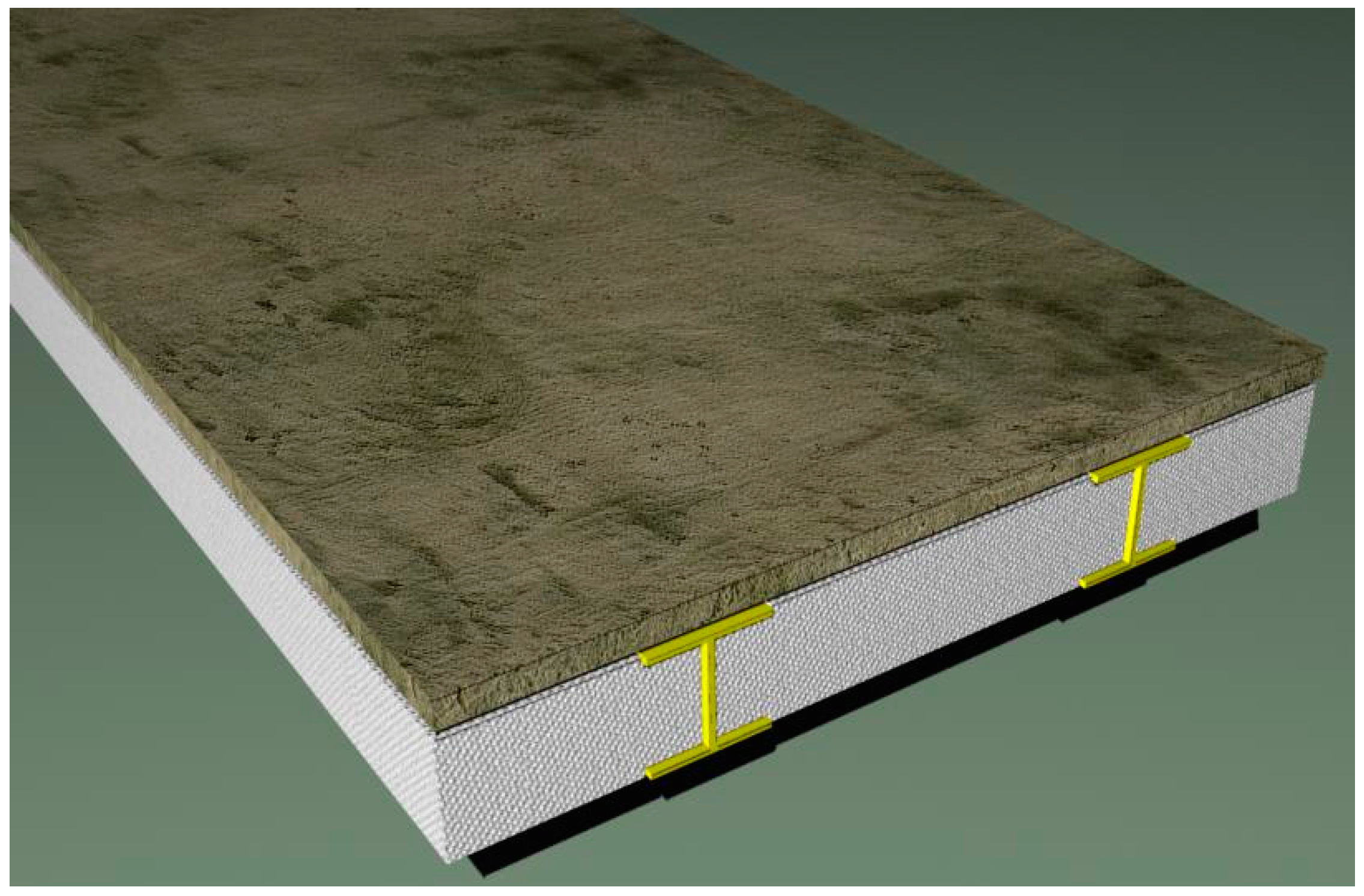
Following this research line on innovative systems, a composite slab made of a fiber-reinforced concrete top laid on glass fiber reinforced polymer (GFRP) I-section profiles is being developed at the Federal University of Santa Catarina, Brazil (UFSC), for footbridge deck applications. The slab consists of a concrete top laid on GFRP I-section pultruded profiles, filled in with foam blocks, as shown in Figure 1. In previous works, this slab system was verified under static loads, both numerically and experimentally [1,2], showing very good results under bending for two systems, with different I-section profiles. Initial studies on the slab durability and its behavior under concentrated loads have also been performed [3]. As this slab system is lighter and slenderer as compared to conventional reinforced concrete slabs, it becomes necessary to verify its behavior under dynamic loading.
The aim of this work is to investigate the dynamic behavior of the slab system under development at UFSC, regarding to vibrations induced by human activities such as walking and jumping. Initially, a brief literature review on modeling of the dynamic loads caused by human activities such as walking and jumping is presented, describing the mathematical models used in the numerical analysis of the slab system. Next, the slab system and the material properties of its components are described. The dynamic behavior of the slab system was verified by means of experimental and numerical analyses. In the experimental analysis, two prototypes of 0.80 m width and 4.00 m span were subjected to walking and jumping by several volunteers. In the numerical analysis, the slab prototype was modeled by finite elements, using SAP2000 software [4]. The slab was subjected to dynamic loads representing the experimental testing, applying mathematical models developed by other authors. The elastic properties of concrete were estimated using equations given in design codes, whereas the elastic properties of the GFRP profiles were obtained analytically and also experimentally.
Results of the experimental and of the numerical analysis showed that even though the fundamental frequency of the slab under study is much larger than the limit recommended by international codes regarding human comfort criteria, a dynamic analysis of the slab still needs to be performed.
2. Human Sensitivity to Vibrations—Brief Literature Review
The development of structural systems as well as of advanced materials in the past decades gave rise to the construction of lighter and more slender structures with larger spans. Such structures are in general more susceptible to vibration effects caused by dynamic actions, such as wind, traffic of vehicles and people, earthquakes, as well as equipment in nearby construction sites.
People are daily exposed to vibrations on floor slabs and on footbridges, caused by different sources of excitation. The evaluation of human sensitivity to these vibrations involves psychological and physical aspects [5]. As for footbridges and walkways, the most import dynamic actions are the ones related to human activities like walking and jumping. The resultant human-induced vibrations may cause serviceability problems as well as discomfort to the users [6]. The main factors that may influence human sensitivity are the position (standing, sitting or lying), the type of activity being performed, age, gender, mood, vibration frequency, displacement amplitudes, damping, and acceleration of the dynamic excitation.
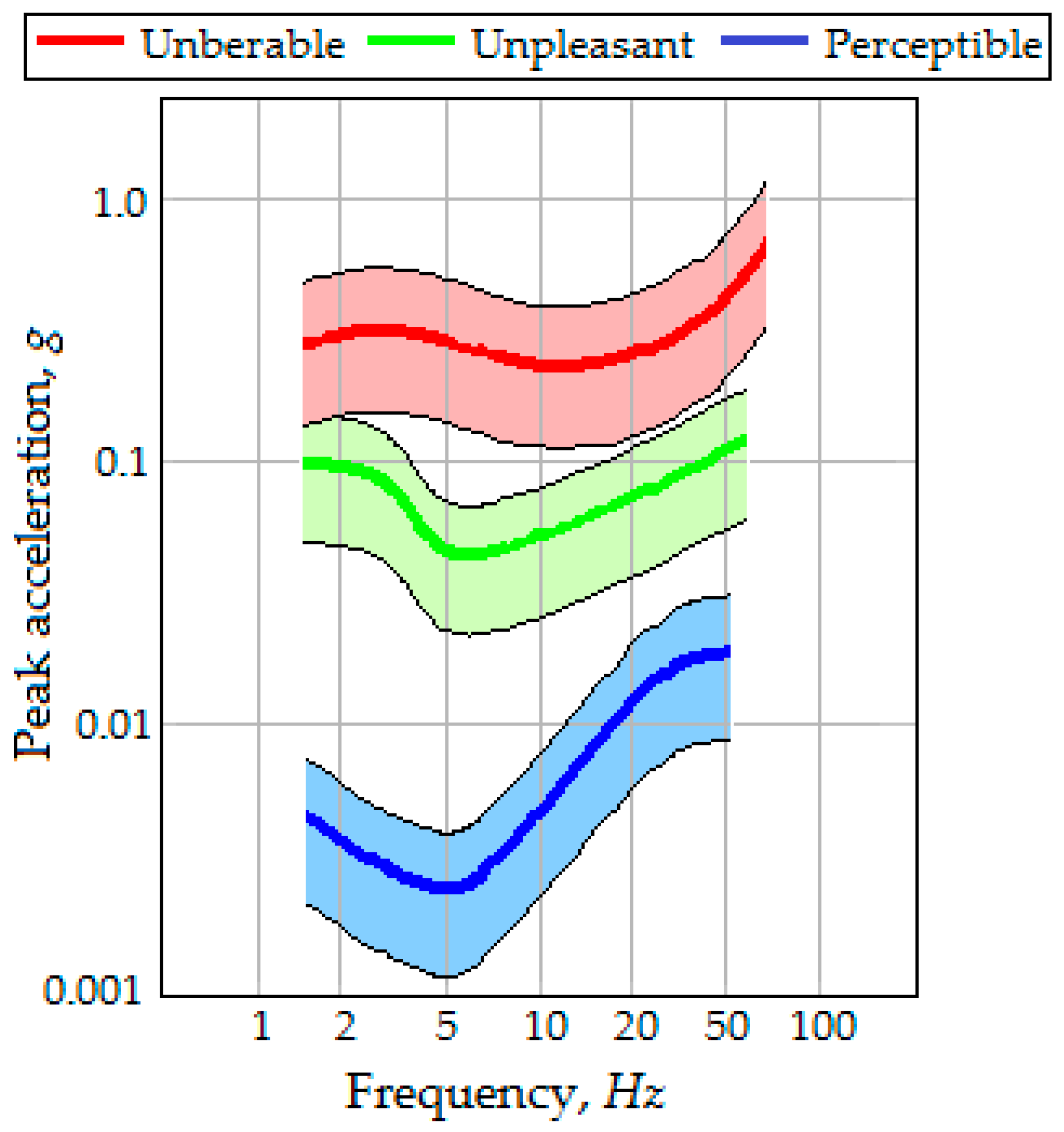
Reiher and Meister [7] investigated the effect of harmonic vibrations on people in different postures on a test platform, subjected to various excitation frequencies, amplitudes and directions. Results from this study were presented in a scale graph of human perception as a function of excitation frequency and amplitude. Similar scales based on experiments of vertical short-duration vibration, like the one experienced by footbridge users, have also been proposed. Figure 2 presents the scale graph proposed by Goldman [8]. This scale shows an interaction between the peak acceleration and the frequency to human perception.
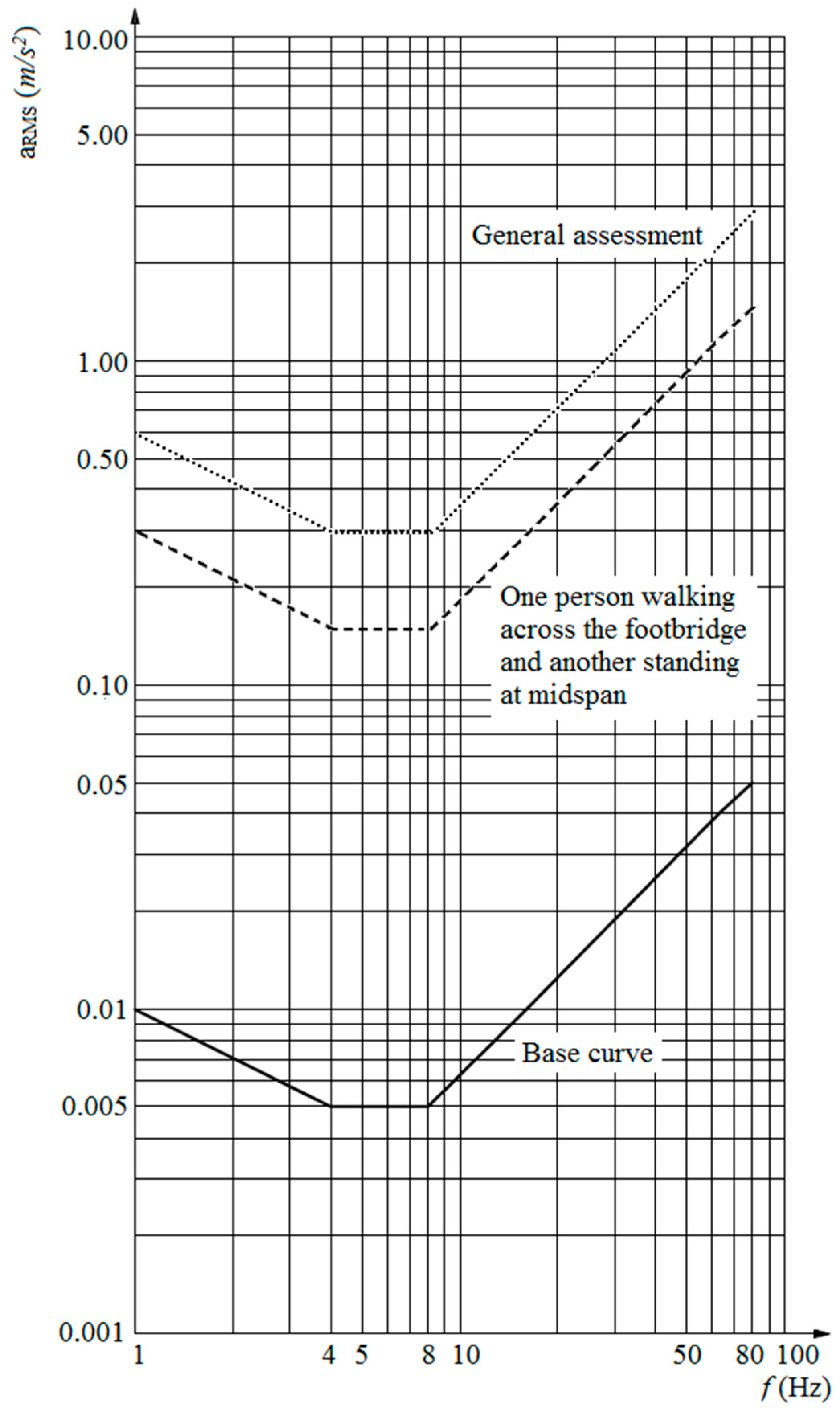
Other design guidelines, however, do not use peak acceleration, but rather, apply the root-mean-square (RMS) acceleration to verify the level of admissible vibrations. EN 1990 [9], the Eurocode basis of structural design, allows a maximum RMS acceleration of 0.7 m/s2, and a smallest natural frequency of 5 Hz for comfort criteria. ISO 10137 [10] guidelines for serviceability in buildings suggests using the curves presented in Figure 3. This guideline permits higher RMS accelerations when a general assessment of footbridge vibrations is performed than to the scenario of a person standing at midspan while another crosses the footbridge.
Dynamic Loads Generated by Human Activities
The dynamic loads generated by human activities can be separated into two groups, according to the person-structure interaction: (a) when there is loss of contact with the structure, like in running and jumping; (b) when there is not a loss of contact with the structure, like in walking.
While walking or running, a human being produces a dynamic loading that can be represented by a force varying in time with components in three directions: vertical, lateral and frontal. The vertical component has been the most investigated one, since it presents greater amplitudes as compared to the other components [5]. This dynamic force is produced by the acceleration and deceleration of the body mass. For walking, it has been stated that its frequency range is between 1.6 to 2.4 Hz [11].
Even though there has not been the same comprehensive investigation for running or jumping activities, it is considered that the typical frequency range for running is 2.0 to 3.5 Hz while for jumping is 1.8 to 3.4 Hz [11].
Mathematical Modeling for Walking and Jumping
To describe loads induced by walking and jumping, mathematical models in the frequency domain as well as in the time domain can be found in the literature. In this work, only a deterministic time domain model that aims to establish a general load model for each type of human activity is considered. It is assumed that the induced force is equal in both feet. This force can be represented by a Fourier series as described by Equation (1):
where is the resulting transient load; is the time in seconds; represents the person’s weight; is the number of the ith harmonic; is the number of harmonics to be considered; represents the dynamic coefficient for the ith harmonic; is the step frequency and is the phase angle, between the ith harmonic and the first one.
For walking, Varella [12] proposed a modification of Equation (1), as presented in Equations (2) to (5). He considered that the human induced loads can be appropriately described by considering the first four harmonics of the Fourier series. This load model considers that the generated time function has a space and time description. This more realistic load model has been used in similar studies [13,14], and therefore is adopted here.
In Equation (2), Fm is the maximum value of the Fourier series, which is given by Equation (3); fmi is the amplification factor due to heel impact; Tp is the step period; and C1 and C2 are coefficients defined by Equations (4) and (5), respectively.
A value of 1.12 may be used for the amplification factor due to heel impact even though this value could vary according to the walking person [13]. For the dynamic coefficients αi, Varela [12] presented the best-fit polynomial functions (Equations (6) to (9)) obtained from the data presented by Rainer, Pernica and Allen [15]:
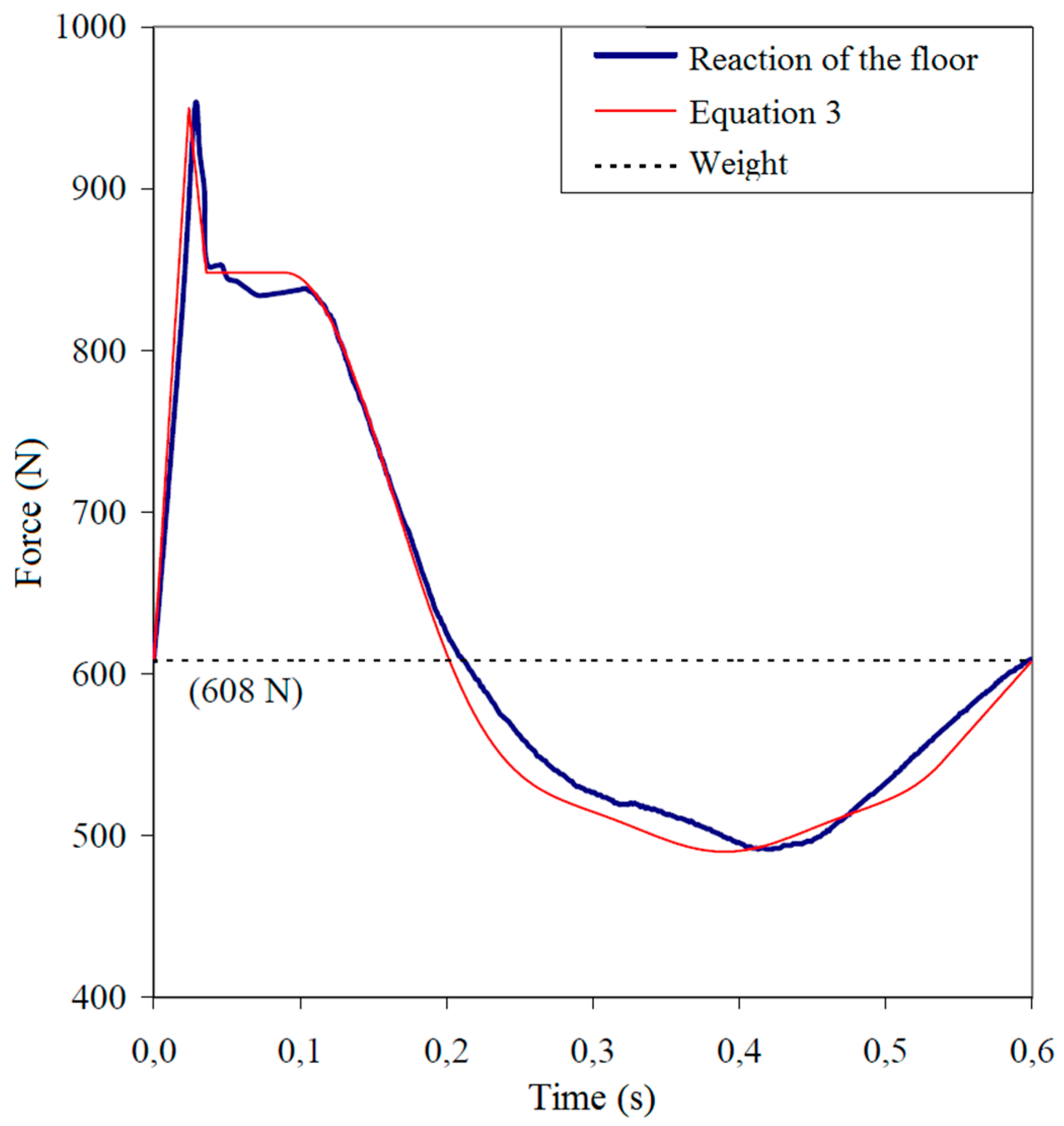
The phase angles are equal to: ϕ1 = 0; ϕ2 = π/2; ϕ3 = π; ϕ4 = 3π/2. By using this model, the loads induced by walking observed by Ohlsson [16] could be appropriately described, as can be seen in Figure 4. In this work, Equations (2) to (9) will be used to model the walking load in the numerical analysis (subsection 4.2).
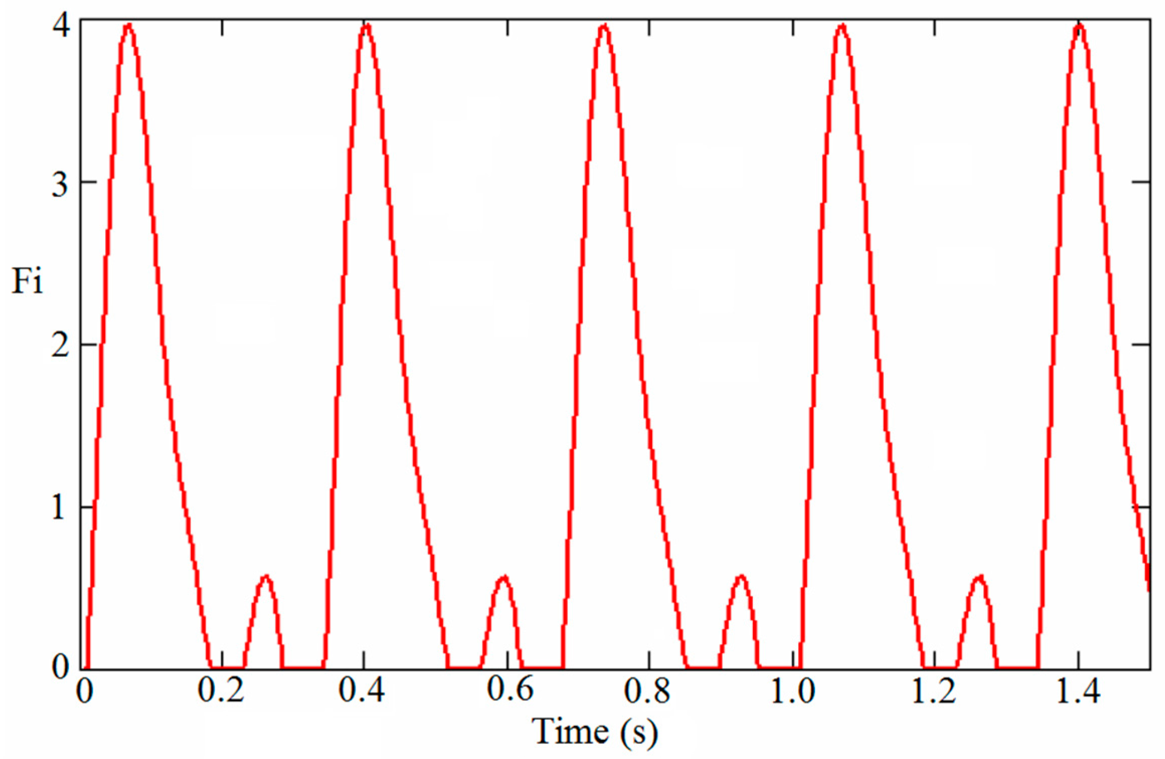
David et al. [17] modeled the force generated by a vigorous jumping action, based on Bachmann et al. [11], by considering a frequency of jumping of 3 Hz, and the first three harmonics with dynamic coefficients of 1.7, 1.1, and 0.5, respectively. The phase angles were ϕ1 = 0; ϕ2 = ϕ3 = π [1 − (fptc)] = 1, with the contact time with the structure, tc as 0.2 s. Figure 5 presents the resultant load function proposed, Fi(t). The jumping transient load can then be obtained by multiplying Fi(t) by the person’s weight, G. This resulting load will be used in the numerical analysis (subsection 4.3) to model the jumping cases.
3. Composite Slab Concrete/GFRP Profiles
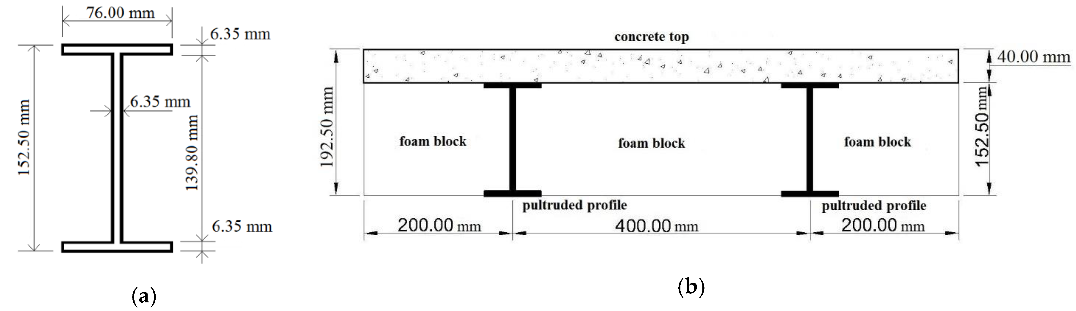
The slab system used in this study is shown schematically in Figure 6. Narrow flanged (NF) I-section GFRP profiles with the dimensions shown in Figure 6a have been selected. The foam (expanded polystyrene or EPS) blocks used for filling are non-structural and have been cut for a perfect fit; they have the usual dimensions employed in precast concrete slabs. The profiles and the foam blocks serve also as formwork for the wet concrete. They are designed to sustain constructive loads, avoiding thus the use of bracing.
In order to restrain cracking due to plastic shrinkage, short polypropylene fibers are added to the concrete top, with a volume fraction of 0.1% [1,18]. An epoxy-based resin is utilized for bonding the concrete to the profiles at the interface. This resin avoids water penetration, and thus aids to prevent alkali attack in the profile glass fibers.
After curing of concrete, the two components, concrete and GFRP profiles, are joined together and behave structurally as a precast slab. A spacing of 400 mm was defined between the profile axes, while the concrete top thickness was chosen to be 40 mm, based on the recommendations for precast slabs given in the Brazilian Code NBR 14859-1 [19]. These dimensions avoid buckling of the profile walls and shear failure of the concrete top [20].
A one-way action was assumed for the flexure design of the composite slab system. A strip of 0.80m width was taken as a representative section, as displayed in Figure 6b. In the design, care was taken to keep the profiles working in tension and the concrete top almost entirely in compression, taking at the most advantage of both materials.
This slab system can be employed either supported by longitudinal beams, with the profiles axis disposed perpendicular to the footbridge longitudinal axis, or supported by transverse beams, with the profiles axis disposed parallel to the footbridge longitudinal axis.
3.1. Material Properties
The selected GFRP profiles are composed of fiber glass rovings (disposed parallel to the profile longitudinal axis) embedded in a polyester matrix, with a fiber volume fraction of 60%, and of laminates made of continuous strand mats (CSM), consisting of randomly-oriented fibers.
It is initially assumed that the profile web and flanges are laminated composites with the same lay-up and equivalent orthotropic mechanical properties. The mechanical elastic properties of each individual laminae can be obtained using the Rule of Mixtures by using the elastic properties of the fibers, resin, and mats as given by the fabricator [21]. The profile elastic properties can then be estimated from the laminae properties by using the Classical Lamination Theory with results shown in Table 1.
The elastic properties of the GFRP profiles were also obtained experimentally from three-point bending tests by following a procedure proposed by Bank [22] based on the Timoshenko Beam Theory. It considers that the profile behaves as an equivalent isotropic material. The equivalent longitudinal (E) and shear (G) moduli of the GFRP profiles were found to be 26.21 and 4.29 GPa, respectively. A more detailed description of this procedure and experiments can be found in Santos Neto and La Rovere [23].
Concrete was designed for a compressive strength of 30 MPa at 28 days. The secant modulus of elasticity (Ec) was obtained according to ACI 318 recommendation [24] yielding a value of 26.07 GPa. The usual value of 0.2 was adopted for Poisson´s coefficient, resulting in a shear modulus (Gc) of 10.86 GPa.
3.2. Design and Static Analysis
Previous studies [1] have shown that the Serviceability Limit State (SLS) tends to govern the design of composite slabs made of concrete and GFRP materials for footbridge deck applications. The composite slab under study was then initially designed under bending for service loads, without considering long term effects. A representative slab strip of 0.8 m width (see section shown in Figure 6) was selected for the analysis. A total dead load (DL) equal to the self-weight (0.846 kN/m) plus an additional load of 1.2 kN/m, due to wearing surface and guardrails, plus a live load (LL) of 4 kN/m corresponding to the usual pedestrian load of 5 kN/m2, were considered acting along the span of the simply supported slab strip. One-way action was assumed and the deflections in the slab were calculated using the Timoshenko Beam Theory (TBT), combined with the Transformed Area Approach. The maximum deflection in the slab, at midspan, considering shear deformation, can be found by Equation (10):
where: v is the maximum displacement; L is the span; q is the design service load uniformly distributed along the span; EI is the flexural stiffness of the transformed section; GA/fs is the shear stiffness of the transformed section, in which fs is the shear factor.
The design service load was found considering the quasi-permanent load combination (q = DL + 0.4LL) [9]. The slab section shown in Figure 6 was transformed into an equivalent GFRP section, by assuming that concrete and GFRP were perfectly bonded and behaved linear-elastically. It was also assumed that concrete remains uncracked under service loads. By using the equivalent isotropic moduli of the GFRP profiles E, G and the estimated values for the concrete moduli Ec, Gc, defined in Section 3.1, the resulting properties of the transformed section were calculated in Table 2.
By inserting all of these values in Equation (10), and by adopting the allowable limit of L/250 given in the Brazilian code NBR 6118 [15] recommendations, a maximum allowable span of 4.65 m was found for the composite slab strip. It then verified the assumption that the concrete top does not crack under service loads.
Next, the composite slab was verified at the Ultimate Limit State (ULS). Three possible failure modes were considered: (1) flexural failure caused by crushing of the extreme compression fiber in the concrete top; (2) shear failure in the GFRP profile at the top flange/web intersection, and (3) bond failure at the GFRP profiles/concrete top interface. For flexural failure, the ultimate bending moment Mu can be calculated from force equilibrium, strain-compatibility conditions and the constitutive behavior of the materials. It was assumed that GFRP materials behave linear-elastically and that concrete was a nonlinear elastic material. The concrete top and the GFRP profiles were assumed to be perfectly bonded and the tensile strength of concrete was neglected. The equivalent rectangular stress block as defined by the ACI 318 [24] was adopted. Results of ultimate efforts are shown in Table 3. In this table, the ultimate shear Vu1 was obtained using an estimated theoretical value for the ultimate shear stress in the GFRP laminae, obtained from Halphin-Tsai equations [21], and Vu2 was found from the bond strength at the interface concrete/GFRP, which has been measured experimentally [1].
For the maximum span of 4.65 m, the design efforts in the simply supported slab strip were found by considering the load combination 1.2DL + 1.6LL [24]. These efforts are shown in Table 3, with the resulting safety factors (design/ultimate efforts). As it can be observed from Table 3, the critical failure mode is shear failure in the GFRP profile at the top flange/web intersection (safety factor Φs1 = 0.51). Although the required safety factors have not yet been established in the Design Codes for the case of concrete/GFRP composite slabs, a safety factor of at most 0.50 should be adopted, since a brittle kind of failure is expected in such structures. Hence, in order to attend both serviceability and ultimate limit states, the span of the composite slab was reduced to 4.0 m (Φs1 = 0.44).
In order to verify the stiffness and the ultimate efforts estimated in the design of the composite slab under static bending, experimental tests were also carried out. Two slab prototypes of 0.8 m width and 4.0 m of span were tested under 4-point test bending. The loads (P) were applied at a distance (a) of 1.575 m from the supports.
Initially the slab stiffness was investigated by applying on the prototypes two concentrated loads (P) of 4.63 kN, in such a way to obtain the same maximum bending moment produced by a uniformly distributed load (3.646 kN/m) for the service load combination (DL + 0.4 LL). It was observed during the tests that the slab behavior was basically linear elastic under service.
The maximum displacement at midspan can be obtained theoretically using TBT, by means of Equation (11):
where: v is the maximum displacement; L is the span; P are the concentrated loads applied symmetrically on the slab; a is the distance between the applied loads and the supports; EI is the flexural stiffness and GA/fs is the shear stiffness of the transformed section (see Table 2).
Comparison between theoretical and experimental values of maximum displacement is shown in Table 4. It can be observed from the table that the theoretical value gives a good estimate for the average value obtained experimentally from the slab prototypes.
Next, the loads were increased on the prototypes (I and II) until failure. Comparison between ultimate efforts estimated theoretically and obtained experimentally is summarized in Table 5. It can be observed that the prototypes showed different failure modes (I showed bond shear failure, and II showed shear failure in the profile at the web/flange interface). In prototype I, a premature bond shear failure occurred at the interface of the concrete top and only one of the GFRP profiles, which was probably due to bad finishing of the concrete top observed in a small region, giving rise to a non-uniform load application along the slab width. Nevertheless, in spite of the different failure modes, both prototypes fail at a load (VI = 38.5 kN and VII = 39.0 kN), close to the estimated one (Vu = 40.1 kN).
In the following, the dynamic behavior of the composite slab will be investigated.
4. Dynamic Behavior of the Composite Slab
The dynamic behavior of the composite slab under human activities was investigated both experimentally and numerically. For the experimental analysis, two prototypes of 0.8 m width and 4.0 m of span, representing a slab strip (same geometry as used for the static tests), have been built and subjected to walking and jumping by several volunteers. In the numerical analysis, the slab prototype was modeled by finite elements and subjected to transient loads that simulate the tests, using the mathematical models already described in Section 2.
4.1. Theoretical Fundamental Frequency of the Composite Slab
In order to aid planning the dynamic experimental program, the fundamental frequency of the composite slab was initially estimated by a simplified theoretical model based on beam analogy combined with the Transformed Section approach. The composite slab is considered as a linear element (beam) of equivalent homogenous and isotropic material, with distributed mass along its length. Thus, the beam equivalent fundamental frequency (ω1) can be obtained from Equation (12), using the equation based on Fourier series [25].
where: EI is the flexural stiffness of the transformed or homogenized section; L is the beam length; and is the beam mass per unit length.
By introducing the flexural stiffness of the homogenized section given in Table 2, the mass per unit length (0.0863 ton/m) is found from the slab total self-weight, and the length L = 4.00 m in Equation (12), the value of 74.66 rad/s is found for the fundamental angular frequency (ω1), which corresponds to a frequency f1 of 11.88 Hz.
4.2. Experimental Analysis of the Composite Slab
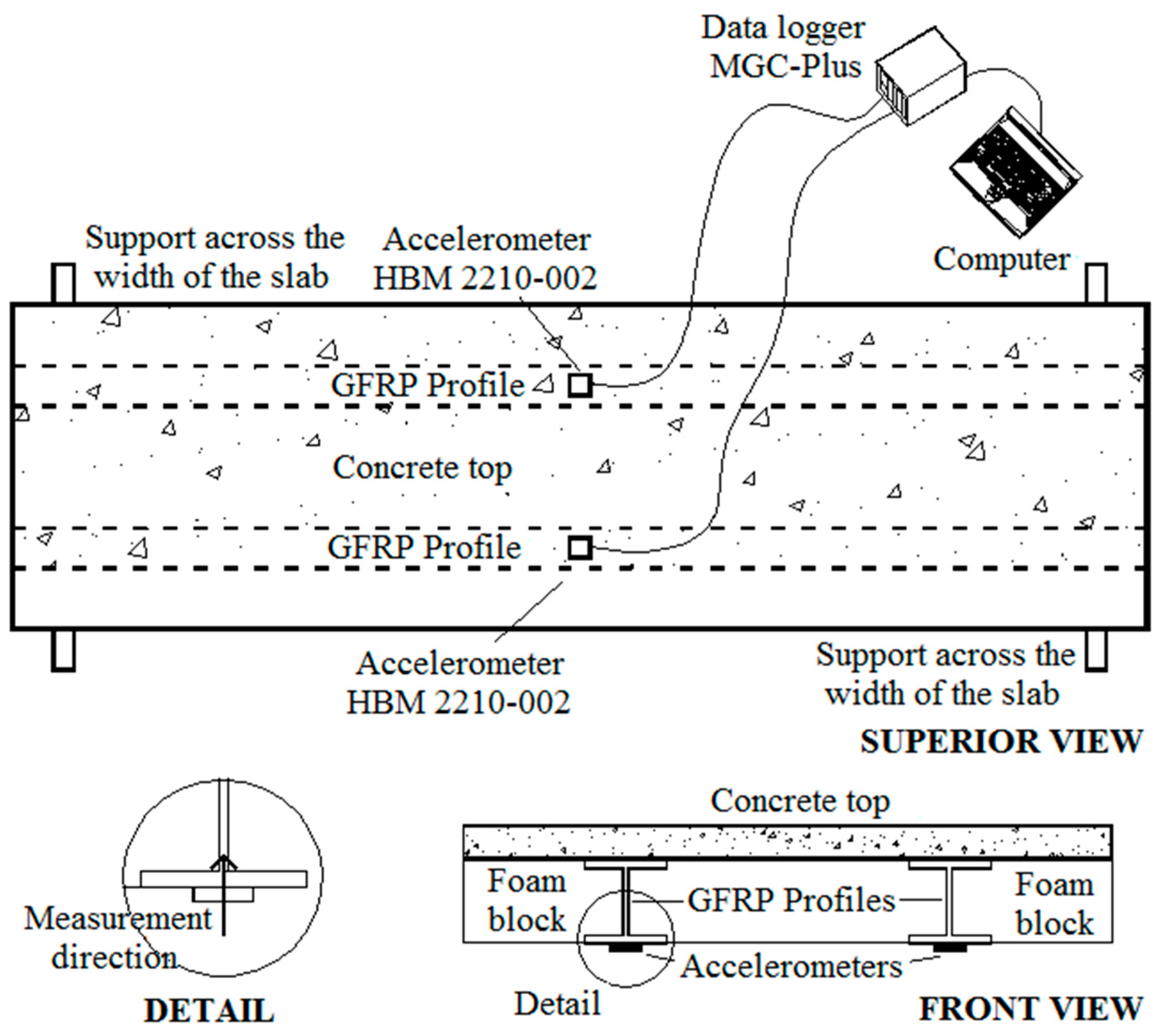
Three types of vibration tests were performed on the slab prototypes: (i) heel-drop, (ii) walking and (iii) jumping. The test setup and instrumentation utilized are illustrated in Figure 7. Vertical accelerations were measured at midspan by means of two accelerometers, placed at the bottom of the GFRP profiles, connected to a data acquisition system. Data were acquired at a time interval of 0.01s, thus, frequencies up to 50 Hz could have been recorded. A total of five volunteers, whose characteristic data are given in Table 6, participated in the tests. All volunteers used soft sole shoes during the tests.
Initially, the fundamental frequency and the damping factor of the composite slab were experimentally obtained through the heel-drop test. The average value obtained for the damping factor was utilized later in the numerical analysis (see subsection 4.3). In the sequence, the composite slab was submitted to walking and jumping tests.
4.2.1. Heel-Drop Test
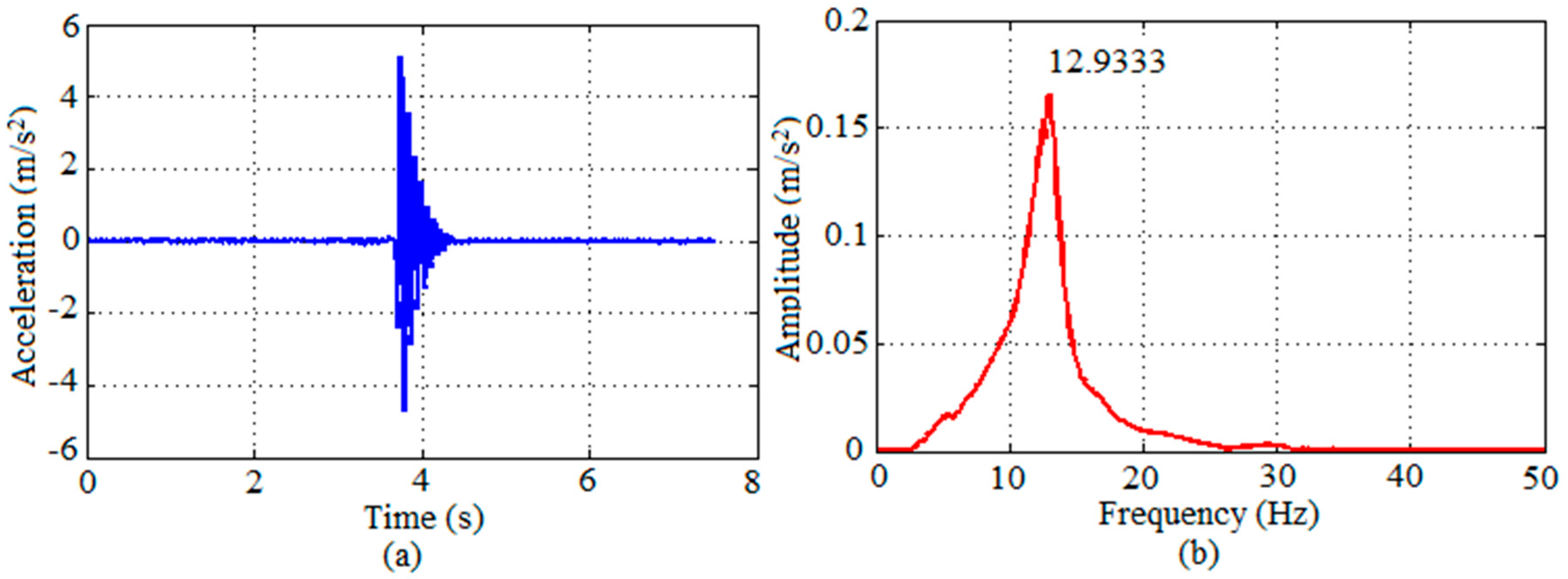
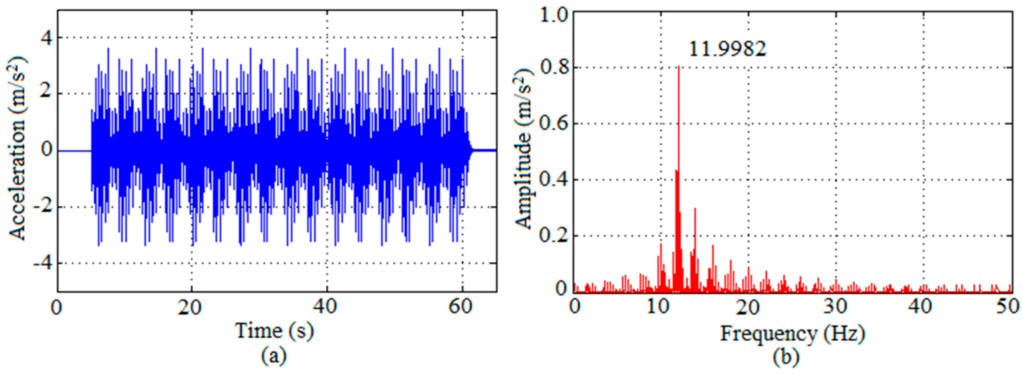
To obtain the fundamental frequency of the structure, the prototypes of the experimental program were initially subjected to the heel-drop test, as recommended by the Canadian Code CAN3-S16.1-M84 [26]. The test consisted of a person standing on his toes and letting himself fall on his heels on the slab. Figure 8 presents the time-domain response as well as the amplitude peak response of the slab in the frequency-domain for one prototype, obtained from the test performed by Volunteer 4. Similar graphs not shown here were obtained from the tests performed by the other volunteers. The damping factor was found by means of the logarithmic decrement method in the time-domain response.
Table 7 presents the fundamental frequency and the damping factor obtained for each prototype, from each volunteer test. It can be seen that the results in terms of fundamental frequency are quite uniform, whereas in terms of damping factor some variation is observed among the different volunteers. Average values of 12.64 Hz and 4.96% were obtained for the fundamental frequency and the damping factor, respectively. This value of damping factor falls between the interval (1.5% to 5.0%) given in ISO 10137 [10] for fully composite concrete/steel beams with shear connectors, which is a similar structure to the composite slab studied in this work.
4.2.2. Walking Test
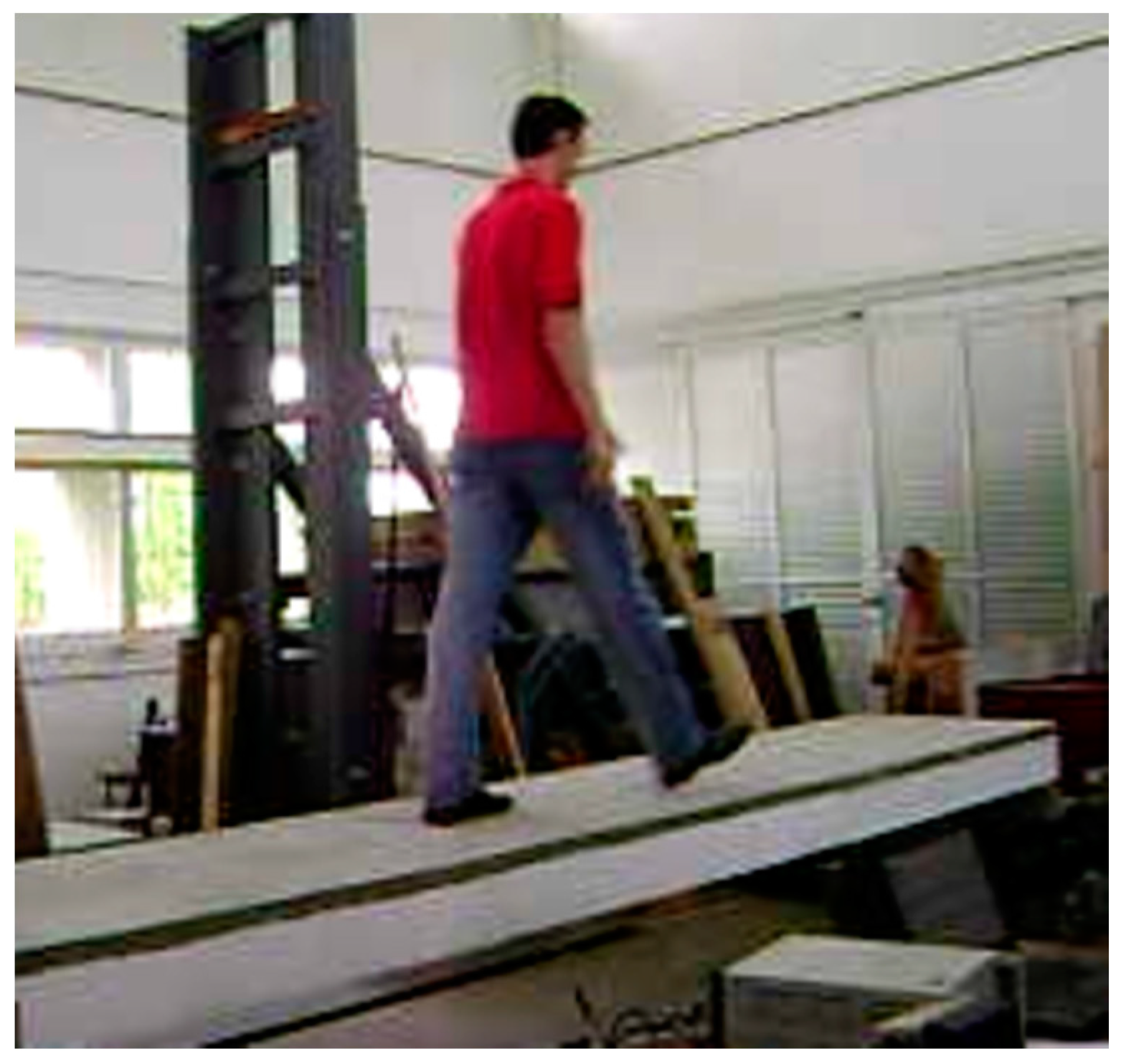
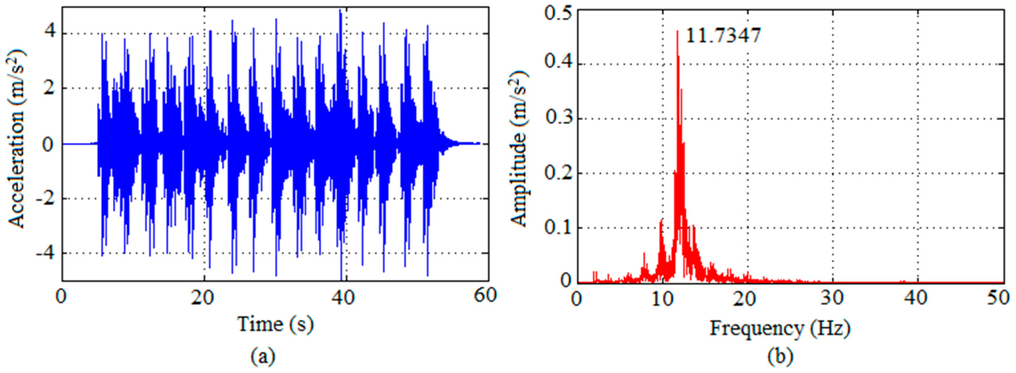
The walking test consisted of a volunteer walking on the slab prototype, as shown in Figure 9, resulting in an excitation frequency of about 2 Hz. To allow an interaction person-structure, i.e., that the volunteer gets in rhythm with the slab, a total of eight walks on each prototype were performed. Results of the slab response to the walking tests are given in terms of graphs of acceleration (average value obtained from the measurements of the two accelerometers) versus time, with its respective spectrum. Figure 10 shows the results obtained from the test performed by Volunteer 4. Similar results, not shown here, were obtained from the tests performed by the other volunteers. Table 8 presents the high peak accelerations and the RMS accelerations obtained from the tests performed by all volunteers.
Regarding human-sensitivity, high peak accelerations between 3.5 to 6.4 m/s2 (≈ 0.4 to 0.7 g) were attained in both prototype responses, considering all the volunteers, which for a frequency around 12 Hz lie in the unbearable range of vibration perception in Goldman’s scale (see Figure 2). In terms of RMS accelerations, the results varied from 0.5 to 1.4 m/s2, with an average of 1.05 m/s2 for both prototypes. These results are above the RMS acceleration limit (using general assessment) for human comfort by ISO 10137 [10], according to Figure 3.
4.2.3. Jumping Test
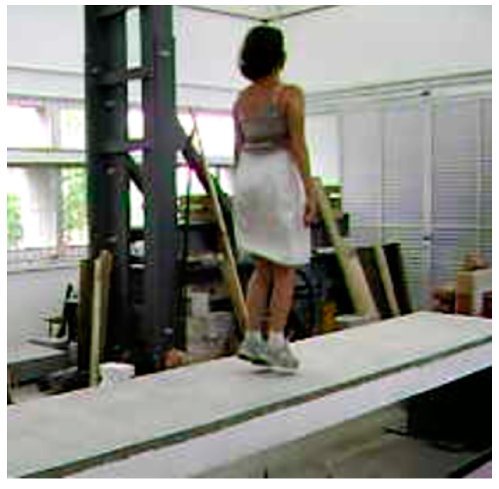
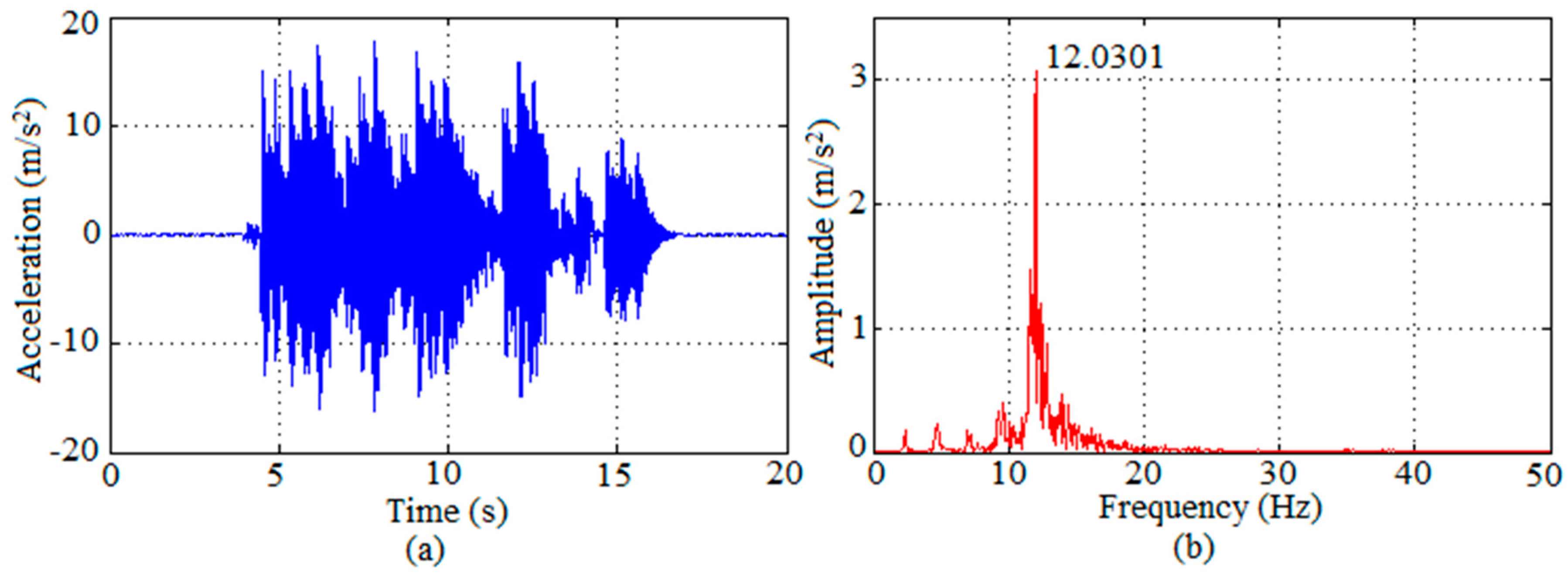
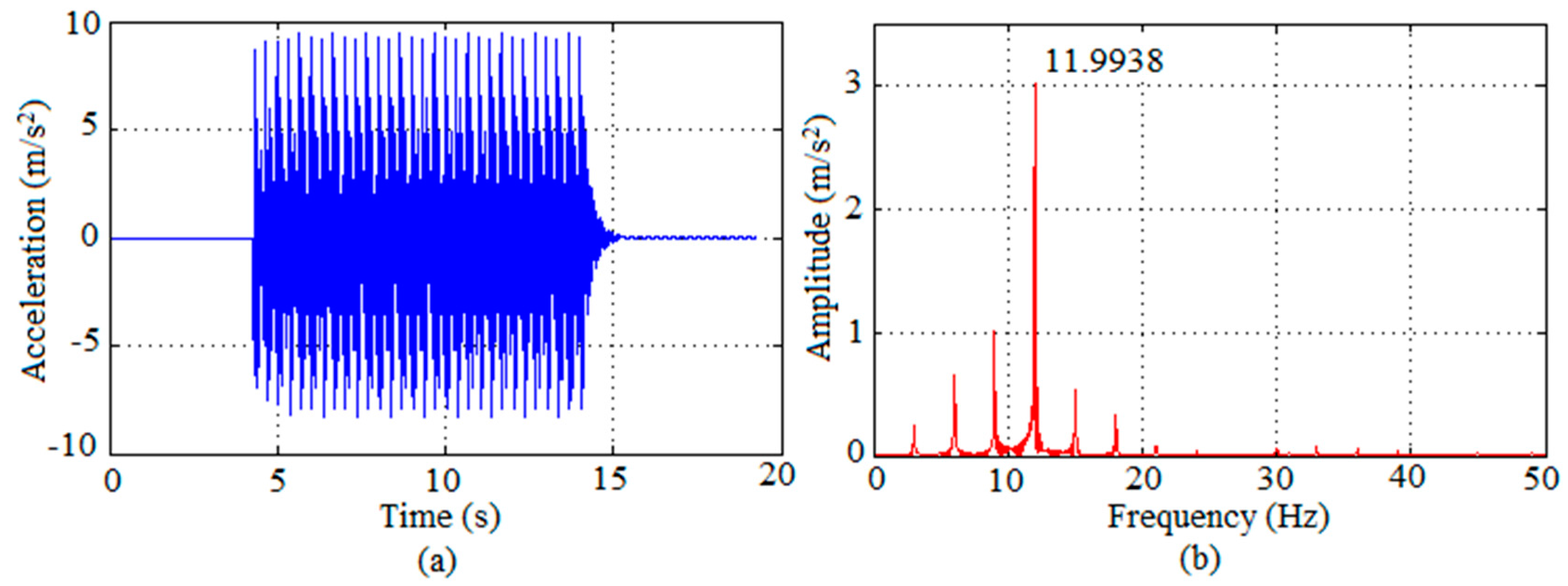
For this test, the volunteers applied about 30 jumps in 10 seconds on the prototypes at the center, as shown in Figure 11, seeking to apply a jumping load with a frequency of around 3.0 Hz. Results from the test performed by Volunteer 4, in terms of response acceleration in time and frequency domain, can be seen in Figure 12. Table 9 presents the high peak accelerations and the RMS accelerations obtained from the tests performed by each volunteer.
Higher peak accelerations (around 0.5 to 1.8 g) were attained as compared to the ones observed in the walking tests. For a frequency of about 12 Hz, these accelerations are classified as unbearable according to the scale presented in Figure 2. By means of RMS accelerations, the results varied from 1.2 to 5.0 m/s2 for both prototypes. Again, all the values are above the limit recommended for human comfort by ISO 10137 [10], as shown in Figure 3.
4.3. Numerical Analysis
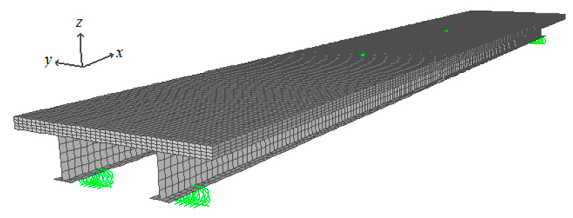
For the numerical analysis of the slab prototypes, the Finite Element Method (FEM) was applied. The slab prototypes were modeled by finite elements as shown in Figure 13, with 8-node solid elements (with incompatible Wilson modes) used to model the concrete top and 4-node Discrete Kirchhoff Quadrilateral (DKQ) shell elements to model the GFRP profiles (the foam blocks were disregarded). Care was taken in the modeling to represent accurately the same boundary conditions as those in the experimental analysis. The analyses were carried out using SAP 2000 [4] computer program.
Materials were assumed to behave linear-elastically. The equivalent orthotropic elastic properties of the GFRP profiles utilized are shown in Table 1, and the elastic properties adopted for concrete were described in subsection 3.1. A damping coefficient of 4.96%, derived from the heel-drop tests, was adopted in all analyses.
The mathematical models for the dynamic loads used to simulate the walking and jumping tests were the ones aforementioned described. In both loadings, three harmonics (n = 3), and the weight of each volunteer were considered. The mode-superposition procedure was utilized in the numerical analyses, considering 20 vibration modes.
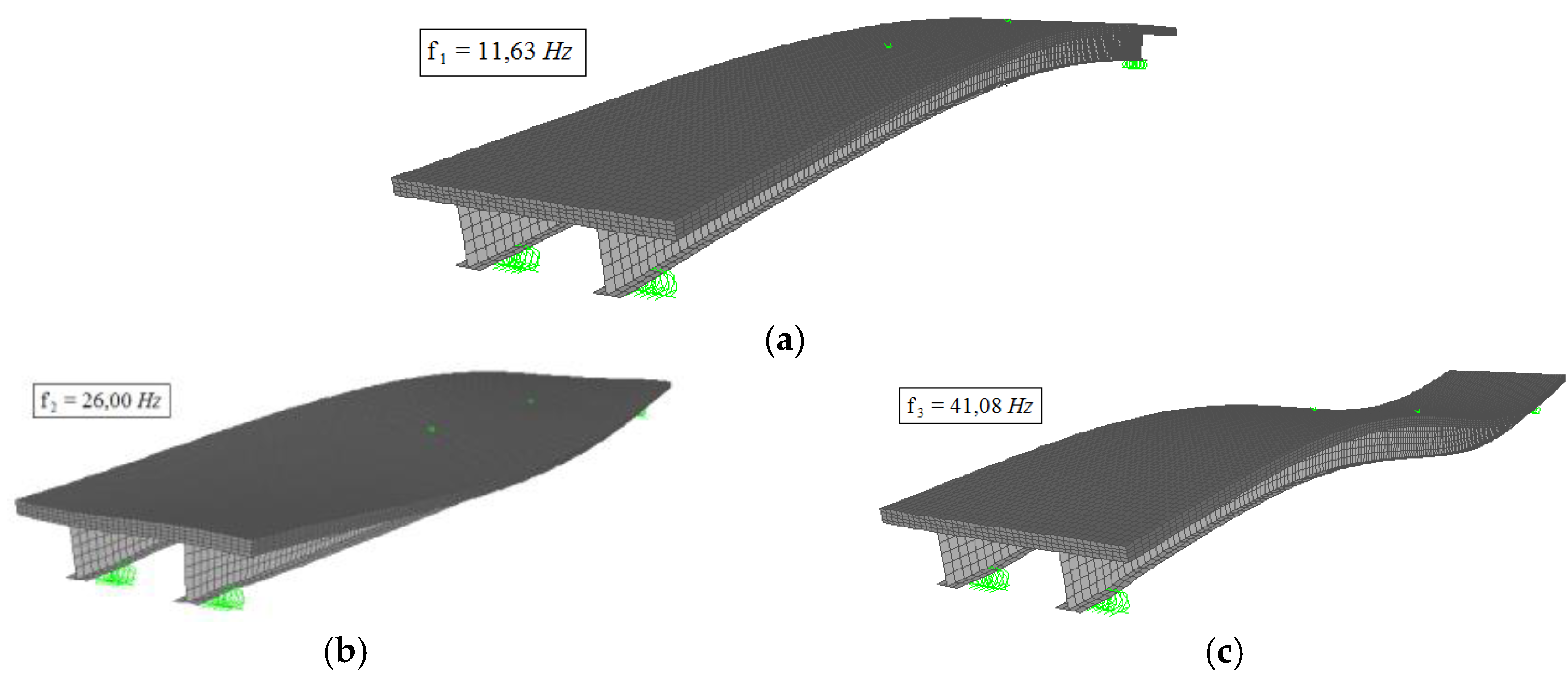
The natural frequencies and respective vibration modes of the slab prototype were obtained using the modal analysis option in SAP2000 [4] program. Figure 14 displays the first three natural frequencies found for the composite slab (11.63, 26.00 and 41.08 Hz) and their respective vibration modes.
The response from all numerical analyses was extracted at the same position of the accelerometers, i.e., at the slab midspan, in the center of the bottom flanges of the GFRP profiles.
In order to simulate the eight turns performed by the volunteers on the composite slab prototype during the test, the walking load, described by Equations (2) to (9), was applied at eight positions along the slab’s span, with a time interval of 0.5 s. Figure 15 shows the slab response for walking obtained numerically, in terms of graphs of acceleration along time and its respective spectrum, considering the weight of Volunteer 4. The acceleration spectrum indicates that the structure responds predominantly in the fundamental frequency, approximately 12 Hz. Peak accelerations of 3.6 m/s2 (around 0.4 g), and corresponding RMS acceleration of 0.97 m/s2 were obtained. These values lie in the unbearable range of vibration perception in Goldman’s scale (Figure 2) for a structure with fundamental frequency of 12 HZ. The RMS value is much higher than the limit given by ISO 10137 [10].
The jumping load described in Section 2 (obtained by multiplying Fi(t), shown in Figure 5, by the person’s weight, G) was applied distributed over two areas, corresponding to the shoe/slab contact area, at the center of the numerical model, in the same position as applied in the experiments. The results for jumping are shown in Figure 16, for the test performed by Volunteer 4, in terms of graphs of acceleration along time and its respective spectrum. From the acceleration spectrum it can be observed, again, that the slab responds primarily at its fundamental mode. The peak accelerations obtained numerically reached at most 9.47 m/s2 with RMS of 3.29 m/s2. These values are much higher than the limit values given by Figure 2 and Figure 3.
5. Analysis and Discussion of Results
The three methods used to estimate the fundamental frequency of the composite slab yielded similar values. The simplified theoretical method, based on beam analogy combined with the Transformed Section approach resulted in a value of 11.88 Hz; the heel impact tests yielded an average value of 12.64 Hz, while the numerical analysis based on the Finite Element Method provided a value of 11.63 Hz. Thus, it can be inferred that the fundamental frequency of the slab prototype is about 12 Hz. According to EN 1990 [9], verification of the comfort criteria should be performed if the fundamental frequency is less than 5 Hz. The composite slab studied here has a fundamental frequency of 12 Hz, and therefore should not present any vibration problem regarding human comfort. However, results of the experimental and numerical analyses have shown the opposite.
The experimental and numerical analyses indicated that the composite slab responded primarily in the first vibration mode (flexural mode), as can be seen from the frequency spectrum shown in Figure 10, Figure 12, Figure 15 and Figure 16. The natural frequencies for the second and third modes of vibration (26.00 and 41.08 Hz) did not show significant amplitudes.
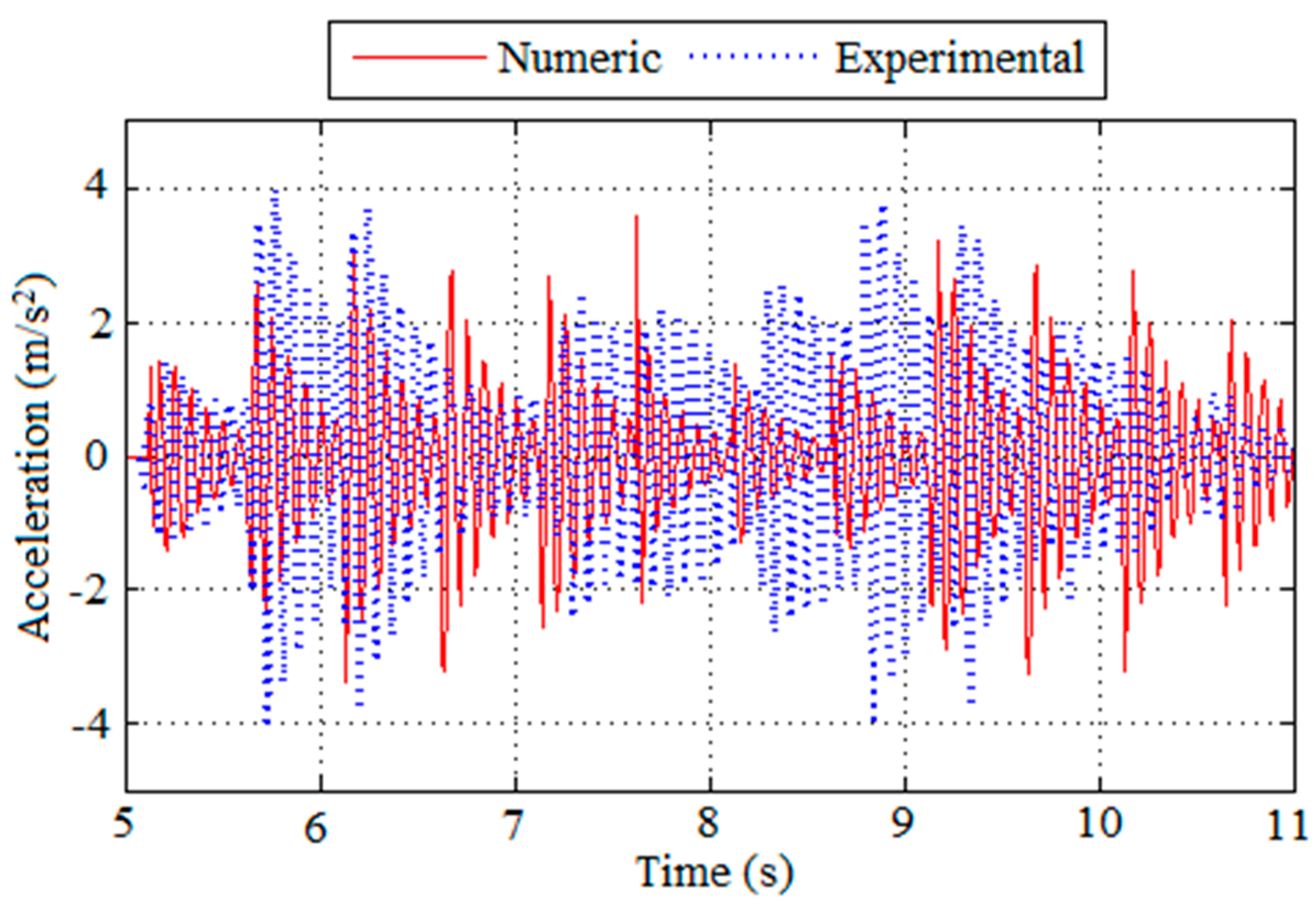
The comparison between the experimental and the numerical results in terms of accelerations obtained for the walking load from Volunteer 4 can be visualized in Figure 17 for the initial cycles. Despite the good agreement, the results from the experimental test in terms of high peak acceleration (5.03 and 4.85 m/s2) are around 35% greater than the results from the numerical model (3.6 m/s2). This difference is also observed for the RMS accelerations, when comparing 1.30 to 0.97 m/s2, found from the experimental and numerical analysis, respectively.
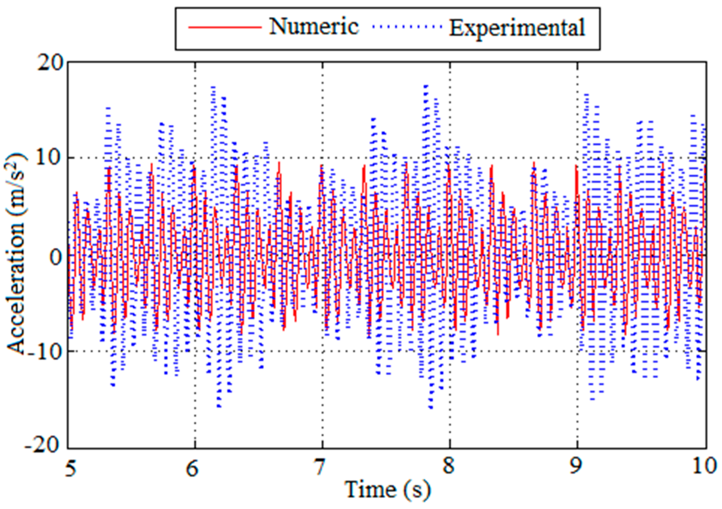
For the jumping loading, the numerical results did not show a good approximation to the experimental results for the initial cycles. Figure 18 displays the comparison between numerical and experimental accelerations obtained from the test performed by Volunteer 4. Although the high peak accelerations from the numerical model are much smaller than the ones from the experimental test (9.47 m/s2 as compared to 14.38 and 17.74 m/s2), the RMS accelerations are similar (3.29 m/s2 for the numerical model and 3.26 and 4.94 m/s2 for the experimental test). This similarity in RMS values may be due to the difficulty of imposing a constant load rhythm on the slab by the volunteers, which does not occur when the slab was analyzed numerically.
Nonetheless, from both the experimental and numerical analyses, the composite slab showed vibrations above the limit of human comfort according to Goodman’s scale (Figure 2) for peak acceleration and also according to ISO 10137 [10] for RMS acceleration. This result indicates that the comfort criteria should be taken into account in the slab design, even though its fundamental frequency is above 5 Hz.
These results have shown that, in spite of their good performance under static loads, composite slabs made of concrete and GFRP profiles tend to be more flexible and slender, and therefore their dynamic behavior under human activities must be considered in the design. Regarding the particular composed slab being developed, a greater efficiency is expected if wide flange GFRP profiles and/or reduced spans are utilized, since that would increase the slab rigidity and consequently its fundamental frequency.
It should be noted that in small specimens, as the ones used in this work, the mass of the person on the slab may have some influence in the results; also, for the walking case, it takes some time until the structure “gets in rhythm” with the applying load.
6. Conclusions
This work investigated the dynamic behavior of a composite concrete/GFRP slab, under development at UFSC, subjected to human activities. By considering a representative slab strip, two prototypes were constructed for the experimental program. A numerical finite element analysis was also performed. From the analyses, the following conclusions could be drawn:
The fundamental frequency of the composite slab is approximately 12 Hz. Although this value is more than twice the limit indicated by EN 1990 (5 Hz), below which a dynamic analysis is required, it was observed that the composite slab showed vibrations above the limit for human comfort.
- The slab responds primarily at its first vibration mode (flexural). The other vibration modes did not show significant amplitudes. This indicates that in a simplified approach, even considering just the first mode in the analysis, should lead to good results
- Results from experimental tests in terms of accelerations were always higher than the ones obtained from the numerical model. In addition, in the experimental tests the peak accelerations did not follow a uniform pattern as the ones observed in the numerical analysis. This may be due to the fact that the volunteers were not able to maintain a constant load rhythm.
- The composite slab was designed under static loads to attend both ULS and SLS requirements, and it was verified experimentally under 4-point bending tests. However, in spite of its apparent stiffness, with a fundamental frequency above 5 Hz, the concrete/GFRP composite slab under study was shown to be sensitive to human activities. Therefore, in addition to the usual verification of ultimate and serviceability limit states, the dynamic behavior of the slab must also be considered in the design.
Acknowledgments
The authors would like to acknowledge the companies CSE Composites, SIKA, Termotécnica, NeoNatex and Polimix for providing the material necessary to the experimental program. Thanks are also due to FAPESC (Fundação de Apoio à Pesquisa Científica e Tecnológica do Estado de Santa Catarina) for the financial support and to CNPq (Conselho Nacional de Desenvolvimento Científico e Tecnológico) for the scholarship granted to the first author.
Author Contributions
Paulo Junges and Henriette Lebre La Rovere conceived and designed the experiments; Paulo Junges performed the experiments; Paulo Junges, Henriette Lebre La Rovere and Roberto Caldas de Andrade Pinto analyzed the data and wrote the paper.
Conflicts of Interest
The authors declare no conflict of interest.
References
- Neto, A.B.S.; La Rovere, H.L. Composite concrete/GFRP slabs for footbridge deck systems. Compos. Struct. 2010, 92, 2554–2564. [Google Scholar] [CrossRef]
- Junges, P. Vibration analysis of a composite slab of concrete and GFRP profiles induced by human activities. Master dissertation, Civil Engineering Department, Federal University of Santa Catarina, Florianópolis, Brazil, 2010. (In Portuguese). [Google Scholar]
- Pinto, R.C.A.; Vieira, D.; La Rovere, H.L. Composite Concrete/GFRP Slabs under Concentrated Loads. In New Developments in Structural Engineering and Construction; Research Publishing Services: Singapore, 2013; Volume 2, pp. 1117–1122. [Google Scholar]
- SAP2000. Integrated Finite Elements Analysis and Design of Structures, 11th ed.; Computers and Structures, Inc.: Berkeley, CA, USA, 2009.
- Živanović, S.; Pavic, A.; Reynolds, P. Vibration serviceability of footbridges under human-induced excitation: A literature review. J. Sound. Vib. 2005, 279, 1–74. [Google Scholar] [CrossRef] [Green Version]
- Bachmann, H. Case Studies of Structures with Man-Induced Vibrations. ASCE J. Struct. Eng. 1992, 118, 631–647. [Google Scholar] [CrossRef]
- Reiher, H.; Meister, F.J. Die Empfindlichkeit dês Menschen gegen Erschütterungen (in German) (The Effect of Vibration on People). Forsch. Ing. Wes. 1931, 2, 381–386. [Google Scholar]
- Goldman, D.E. USN MRI Rept. 1, NM 004 001. March 1948.
- EN 1990. Eurocode 0: Basis of Structural Design; European Committee for Standardization (CEN): Brussels, Belguim, 2002. [Google Scholar]
- ISO 10137: Bases for design of structures-Serviceability of buildings and walkways against vibrations; International Organization for Standardization: Geneva, Switzerland, 2007.
- Bachmann, H.; Pretlove, A.J.; Rainer, H. Dynamic forces from rhythmical human body motions. In Vibration Problems in Structures: Practical Guidelines; Birkhäuser: Basel, Switzerland, 1995; Appendix G. [Google Scholar]
- Varela, W.D. Theoretical-experimental model to analyze vibrations induced by people walking on floor slabs of buildings. D.Sc. Thesis, Federal University of Rio de Janeiro, Rio de Janeiro, Brazil, 2004. (In Portuguese). [Google Scholar]
- Figueiredo, F.P.; Silva, J.G.S.; Lima, L.R.O.; Vellasco, P.C.G.S.; Andrade, S.A.L. A parametric study of composite footbridges under pedestrian walking loads. Eng. Struct. 2007, 30, 615–630. [Google Scholar] [CrossRef]
- Mello, A.V.A.; Silva, J.G.S.; Vellasco, P.C.G.S.; Andrade, S.A.L.; Lima, L.R.O. Dynamic analysis of composite systems made of concrete slabs and steel beams. J. Constr. Steel Res. 2008, 64, 1142–1151. [Google Scholar] [CrossRef]
- Rainer, J.H.; Pernica, G.; Allen, D.E. Dynamic Loading and Response of Footbridges; Institute for Reseach in Construction, National Research Council of Canada: Ottawa, ON, Canada, 1988. [Google Scholar]
- Ohlsson, S.V. Floor vibrations and human disconfort. Ph.D. thesis, Departament of Structural Engineering, Chalmers University of Technology, Götemborg, Sweden, 1982. [Google Scholar]
- David, D.; Tristão, G.; Becocci, L.; Juliani, M.A. Experimental and computational analysis of floors submitted to dynamic loads. In Proceedings of the 3rd International Operational Modal Analysis Conference-IOMAC09, Portonovo, Italy, 4–6 May 2009; pp. 391–400. [Google Scholar]
- Santos Neto, A.B.S. Development of a composite concrete/GFRP slab for footbridge deck systems. Ph.D. thesis, Civil Engineering Dept, Federal University of Santa Catarina, Florianópolis, Brazil, 2006. (In Portuguese). [Google Scholar]
- NBR 14859-1 (2002): Laje pré-fabricada-Requisitos. Parte 1: Lajes unidirecionais; Brasileira de Normas Técnicas (ABNT): Rio de Janeiro, Brazil, 2002. (In Portuguese)
- Deskovic, N.; Triantafillou, T.C.; Meier, U. Innovative design of FRP combined with concrete: Short-term behavior. J. Struct. Eng. 1995, 121, 1069–1078. [Google Scholar]
- Kaw, A.K. Mechanics of composite materials, 1st ed.; CRC Press: New York, NY, USA, 1997. [Google Scholar]
- Bank, L.C. Flexural and shear moduli of full-section fiber reinforced plastic (FRP) pultruded beams. J. Test. Eval. 1989, 17, 40–45. [Google Scholar]
- La Rovere, H.L.; Santos Neto, A.B.S. Flexural stiffness characterization of fiber reinforced plastic (FRP) pultruded beams. Compos. Struct. 2007, 81, 274–282. [Google Scholar]
- ACI 318-11 (2011): Building Code Requirements for Structural Concrete; American Concrete Institute (ACI): Farmington Hills, MI, USA, 2011.
- Clougn, R.W.; Penzien., J. Dynamics of Structures, 2nd ed.; McGraw-Hill Education: New York, NY, USA, 1993. [Google Scholar]
- CAN3-S16.1-M84: Steel Structures for Buildings-Limits States Design, Appendix G: Guide on Floor Vibrations; Canadian Standards Association: Mississauga, ON, Canada, 1984.
Figure 1.
Composite slab concrete/glass fiber-reinforced polymer (GFRP) profiles. Reproduced with permission from Santos Neto, A.B.S., published by Federal University of Santa Catarina, 2006.
Figure 1.
Composite slab concrete/glass fiber-reinforced polymer (GFRP) profiles. Reproduced with permission from Santos Neto, A.B.S., published by Federal University of Santa Catarina, 2006.

Figure 2.
Scale used to measure human sensitivity to vibrations suggested by [8].
Figure 2.
Scale used to measure human sensitivity to vibrations suggested by [8].

Figure 3.
Curves for level of vibrations in the vertical direction for walkways of [10].
Figure 3.
Curves for level of vibrations in the vertical direction for walkways of [10].

Figure 4.
Load function induced by walking proposed by [12], compared to results obtained by [16].Reproduced with permission from Varela, W.D., published by Federal University of Rio de Janeiro, 2004.

Figure 5.
Load function induced by jumping used by [17].
Figure 5.
Load function induced by jumping used by [17].

Figure 6.
(a) Dimension of I-section GFRP profile; (b) Cross-section of the representative strip utilized to study the composite slab behavior.
Figure 6.
(a) Dimension of I-section GFRP profile; (b) Cross-section of the representative strip utilized to study the composite slab behavior.

Figure 7.
Test set-up and instrumentation for the dynamic tests on the composite slab.

Figure 8.
Response of Prototype II to heel-drop performed by Volunteer 4 in terms of graphs: (a) acceleration along time; (b) respective spectrum.
Figure 8.
Response of Prototype II to heel-drop performed by Volunteer 4 in terms of graphs: (a) acceleration along time; (b) respective spectrum.

Figure 9.
Walking test on the composite slab performed by Volunteer 3.

Figure 10.
Response of Prototype I to walking performed by Volunteer 4 in terms of graphs: (a) acceleration along time; (b) respective spectrum.
Figure 10.
Response of Prototype I to walking performed by Volunteer 4 in terms of graphs: (a) acceleration along time; (b) respective spectrum.

Figure 11.
Jumping test on the composite slab performed by Volunteer 4.

Figure 12.
Response of Prototype II to jumping performed by Volunteer 4 in terms of graphs: (a) acceleration along time; (b) respective spectrum.
Figure 12.
Response of Prototype II to jumping performed by Volunteer 4 in terms of graphs: (a) acceleration along time; (b) respective spectrum.

Figure 13.
Finite element model of the composite slab prototype.

Figure 14.
Natural frequencies and respective vibration modes of the composite slab: (a) first mode (bending about y axis); (b) second mode (torsion about x axis) and; (c) third mode (bending about y axis).
Figure 14.
Natural frequencies and respective vibration modes of the composite slab: (a) first mode (bending about y axis); (b) second mode (torsion about x axis) and; (c) third mode (bending about y axis).

Figure 15.
Numerical response of the composite slab to walking loading in terms of graphs: (a) acceleration along time; (b) respective spectrum.
Figure 15.
Numerical response of the composite slab to walking loading in terms of graphs: (a) acceleration along time; (b) respective spectrum.

Figure 16.
Numerical response of the composite slab to jumping loading in terms of graphs: (a) acceleration along time; (b) respective spectrum.
Figure 16.
Numerical response of the composite slab to jumping loading in terms of graphs: (a) acceleration along time; (b) respective spectrum.

Figure 17.
Comparison between acceleration graphs obtained numerically and experimentally from the test on Prototype I performed by Volunteer 4 walking.
Figure 17.
Comparison between acceleration graphs obtained numerically and experimentally from the test on Prototype I performed by Volunteer 4 walking.

Figure 18.
Comparison between acceleration graphs obtained numerically and experimentally from test on Prototype II performed by Volunteer 4 jumping.
Figure 18.
Comparison between acceleration graphs obtained numerically and experimentally from test on Prototype II performed by Volunteer 4 jumping.


Table 1.
Elastic properties of the laminates that form the GFRP profile web and flanges (considered as an equivalent orthotropic material)a.
Table 1.
Elastic properties of the laminates that form the GFRP profile web and flanges (considered as an equivalent orthotropic material)a.
| Elastic Properties | E1 (GPa) | E2 (GPa) | G12 (GPa) | ν12 (GPa) |
|---|---|---|---|---|
| Laminates of GFRP profiles (I section) | 26.73 | 7.19 | 2.44 | 0.341 |
a where 1 is the longitudinal direction, parallel to the longitudinal profile axis, and 2 is the transversal direction of the profile web and flanges.
Table 2.
Transformed section propertiesb.
| x (mm) | EI (kNm2) | GĀ (kN) | n |
|---|---|---|---|
| 30.04 | 1.263 × 10³ | 1.376 × 10⁴ | 0.995 |
b where x is the neutral axis depth; EI is the flexural stiffness; GĀ is the shear stiffness, in which Ā = A/fs and fs is the shear factor; n = Ec/EGFRP is the moduli ratio.
Table 3.
Ultimate Limit State (ULS): Design and ultimate efforts for the composite slab under uniform load (L = 4.65 m).
Table 3.
Ultimate Limit State (ULS): Design and ultimate efforts for the composite slab under uniform load (L = 4.65 m).
| Effort | (a) Bending | (b) Shear Web/Flange | (c) Bond Shear (Interface) |
|---|---|---|---|
| Design Effort | Md = 23.93 kN·m | Vd1 = 20.60 kN | Vd2 = 20.60 kN |
| Ultimate Effort | Mu = 92.26 kN·m | Vu1 = 40.10 kN | Vu2 = 58.02 kN |
| Safety Factor | Φb = 0.26 | Φs1 = 0.51 | Φs2 = 0.36 |
Table 4.
Serviceability Limit State (SLS): Comparison of maximum displacement obtained theoretically and experimentally for the composite slab under 4-point bending (L = 4.00 m; P = 4.63 kN).
Table 4.
Serviceability Limit State (SLS): Comparison of maximum displacement obtained theoretically and experimentally for the composite slab under 4-point bending (L = 4.00 m; P = 4.63 kN).
| Theoretical (TBT) | Experimental | Limit (L/250) |
|---|---|---|
| 9.69 mm | Prototype I = 10.00 mm | 16.00 mm |
| Prototype II = 7.92 mm | ||
| - | Average value = 8.96 mm | - |
Table 5.
ULS: Comparison between ultimate efforts obtained theoretically and experimentally for the composite slab under 4-point bending (L = 4.00 m).
Table 5.
ULS: Comparison between ultimate efforts obtained theoretically and experimentally for the composite slab under 4-point bending (L = 4.00 m).
| Effort | (a) Bending | (b) Shear Web/Flange | (c) Bond Shear (Interface) |
|---|---|---|---|
| Theoretical Ultimate effort | Mu = 92.26 kN.m | Vu1 = 40.10 kN | Vu2 = 58.02 kN |
| Experimental Ultimate Efforta | - | - | VI = 38.50 kN |
| - | VII = 39.00 kNc | - |
c I and II refer to Prototype I and II, respectively.
Table 6.
Characteristics of the volunteers that participated in the tests.
| Volunteer | Mass (kg) | Height (m) | Gender |
|---|---|---|---|
| 1 | 70 | 1.83 | M |
| 2 | 67 | 1.70 | M |
| 3 | 83 | 1.92 | M |
| 4 | 53 | 1.63 | F |
| 5 | 66 | 1.72 | M |
Table 7.
Fundamental frequency and damping factor from heel-drop test.
| Volunteer | Natural Frequency (Hz) | Damping Factor (%) | ||
|---|---|---|---|---|
| Prototype I | Prototype II | Prototype I | Prototype II | |
| 1 | 11.61 | 12.86 | 4.50 | 2.88 |
| 2 | 13.03 | 12.79 | 4.81 | 6.11 |
| 3 | 12.86 | 13.02 | 6.31 | 4.85 |
| 4 | 12.30 | 12.93 | 4.48 | 5.44 |
| 5 | 12.63 | 12.36 | 3.77 | 6.42 |
| Mean value | 12.64 Hz | 4.96% | ||
Table 8.
Accelerations from walking tests (m/s2).
| Volunteer | High Peak Accelerations | RMS Accelerations | ||
|---|---|---|---|---|
| Prototype I | Prototype II | Prototype I | Prototype II | |
| 1 | 5.27 | 4.86 | 0.86 | 0.83 |
| 2 | 4.37 | 3.49 | 0.95 | 0.52 |
| 3 | 6.43 | 6.10 | 1.25 | 1.09 |
| 4 | 5.03 | 4.85 | 1.28 | 1.30 |
| 5 | 5.56 | 3.51 | 1.41 | 0.94 |
| Mean | 5.33 | 4.56 | 1.15 | 0.94 |
Table 9.
Accelerations from jumping tests (m/s2).
| Volunteer | High Peak Accelerations | RMS Accelerations | ||
|---|---|---|---|---|
| Prototype I | Prototype II | Prototype I | Prototype II | |
| 1 | 9.82 | 14.71 | 2.09 | 3.04 |
| 2 | 14.26 | 12.46 | 3.36 | 2.69 |
| 3 | 7.70 | 11.42 | 1.41 | 2.03 |
| 4 | 14.38 | 17.74 | 3.26 | 4.94 |
| 5 | 5.09 | 10.83 | 1.19 | 2.06 |
| Mean | 10.25 | 13.43 | 2.26 | 2.95 |
© 2017 by the authors. Licensee MDPI, Basel, Switzerland. This article is an open access article distributed under the terms and conditions of the Creative Commons Attribution (CC BY) license (http://creativecommons.org/licenses/by/4.0/).
Share and Cite
MDPI and ACS Style
Junges, P.; Rovere, H.L.L.; Pinto, R.C.d.A. Vibration Analysis of a Composite Concrete/GFRP Slab Induced by Human Activities. J. Compos. Sci. 2017, 1, 11. https://doi.org/10.3390/jcs1020011
AMA Style
Junges P, Rovere HLL, Pinto RCdA. Vibration Analysis of a Composite Concrete/GFRP Slab Induced by Human Activities. Journal of Composites Science. 2017; 1(2):11. https://doi.org/10.3390/jcs1020011
Chicago/Turabian StyleJunges, Paulo, Henriette Lebre La Rovere, and Roberto Caldas de Andrade Pinto. 2017. "Vibration Analysis of a Composite Concrete/GFRP Slab Induced by Human Activities" Journal of Composites Science 1, no. 2: 11. https://doi.org/10.3390/jcs1020011