Article

Determination of Processing Parameters for Thermoplastic Biocomposites Based on Hybrid Yarns Using Finite Elements Simulation

1
Department of Textile Technology, Faculty of Textiles, Engineering and Business, University of Borås, SE-501 90 Borås, Sweden
2
Department of Resource Recovery and Building Technology, Faculty of Textiles, Engineering and Business, University of Borås, SE-501 90 Borås, Sweden
*
Author to whom correspondence should be addressed.
J. Compos. Sci. 2018, 2(1), 11; https://doi.org/10.3390/jcs2010011
Submission received: 1 February 2018 / Revised: 19 February 2018 / Accepted: 22 February 2018 / Published: 1 March 2018

Abstract

:
This paper investigates the processing parameters for the compression molding of hemp/PLA hybrid yarn biocomposites and their effect on the final mechanical properties. Finite element simulations are used to develop and assess the processing parameters, pressure, temperature, and time. These parameters are then evaluated experimentally by producing the composites by two different methods, to compare the results of experimentally determined processing conditions to parameters determined by the simulation analysis. The assessment of mechanical properties is done with several experimental tests, showing small improvements for the composites produced with the simulation method. The application of the simulation analysis results in considerably reduced processing times, from the initial 10 min to only three minutes, thereby vastly improving the processing method. While the employed methods are not yet able to produce composites with greatly improved mechanical properties, this study can be seen as a constructive approach, which has the ability to lead to further improvements.

1. Introduction

Thermoplastic biocomposites experience a continuing demand for various industrial applications [1,2]. This is due to several specific advantageous characteristics that can be combined in these materials. Thermoplastics, as opposed to thermosets, offer vastly reduced processing times, highly increased storage times, and favorable recycling capabilities [3]. At the same time, both thermoplastic matrices and natural, mostly plant-based fibers entail a new set of challenges concerning the production and usage of their composites, which can also complicate the spread in their application. There is pressure to achieve properties comparable with petroleum-based composites, and to find a substitute for these environmentally challenging materials, while at the same time not compromising the product quality and efficiency.
The processing parameters for the manufacturing of thermoplastic composites with compression molding are very important and have a direct influence on the mechanical properties of the final composite product. Depending on the individual machine and materials, there might be more or fewer parameters involved, but the three most important ones are the processing pressure, temperature, and time [4]. There are several studies that investigate various aspects of compression molded thermoplastic composites. However, these do not usually focus on the processing parameters. Mostly, the findings are not related to the processing conditions and it is not specified, how the individual parameters were determined. Graupner, et al. [5] produced different natural fiber reinforced PLA composites using 4.2 MPa at 180 °C for 20 min. In a study by Masirek, et al. [6], hemp/PLA films with added plasticizer were compression molded at 180 °C for 3 min, with no indication of a pressure value. Pickering and Aruan Efendy [7] produced composites of hemp fiber mats and PLA sheets, heating them at 170 °C and pressing them only after the PLA was completely melted, at 3 MPa for 3 min. Evidently, all of these authors used a different combination of parameters, which can partly be explained by different equipment and material forms. The lack of information on the origin of the parameters used, leads to the assumption that they were mostly determined by trial and error experiments.
The current study uses hybrid yarns as intermediate composite materials, in the form of unidirectional warp-knitted fabrics, which combine a PLA matrix with hemp fibers. In preceding research by Baghaei et al. [8,9], these have demonstrated promising characteristics, but have not yet led to fully satisfactory composite results. It is necessary to further investigate the materials’ characteristics to determine the right processing conditions needed to create optimized biocomposite products. The following study, therefore, investigates the production and quality of biocomposites based on these hybrid yarn fabrics. This is done by employing the use of composite simulations and comparing the simulation results with experimental examinations. This will evaluate the suitability of composite simulations and investigate the possibility for optimization of environmentally friendly biocomposites.

2. Materials and Methods

2.1. Materials

For the reinforcement of the composites, hemp fibers were used in hybrid yarn form. Hemp staple fibers were supplied by Hempage AG (Adelsdorf, Germany), and possessed an average fiber length of 30 mm, an average diameter of 20–40 μm, and a density of 1.48 g/cm3. Polylactic acid (PLA) fibers were used as the matrix in the hybrid yarns. There were two different kinds of PLA: staple fibers, used for the commingling with the reinforcement fibers, and continuous filaments, used for the co-wrapping of the commingled hybrid yarns as well as for the warp yarn in the warp-knitting process. The PLA staple fibers were provided by the company Trevira GmbH (Hattersheim, Germany), with an average fiber length of 38 mm and a linear density of 1.7 dtex. This PLA has a density of 1.24 g/cm3, a glass transition temperature (Tg) of 60–65 °C and a melting temperature (Tm) of 160–170 °C. The PLA filaments were provided as an air-textured multifilament yarn (72 filaments) by Torcitura Lei-Tsu S.r.l. from Bergamo, Italy. According to the supplier’s information, this PLA has a Tg of 55–60 °C.
The hybrid yarns were produced by a combination of commingling and co-wrapping, with the PLA staple fibers used for the commingling and the filaments for the wrapping. The development of these hybrid yarns is shown in previous publications by Baghaei et al. [8,9,10,11,12]. The hybrid yarns were further processed into unidirectional fabrics by warp-knitting with fiber placement. The fabrics were produced by Engtex (Mullsjö, Sweden). Thin PLA multifilament yarn was used for the knitting in the warp direction. The thicker hybrid yarn was inserted in the weft direction after every course, with a fabric density of 4 courses per cm. The resulting hemp/PLA fabric contains 40 wt % reinforcement fibers and 60 wt % PLA and has a mean surface weight of 261 g/m2.

2.2. Methods

2.2.1. Finite Element Method

The finite element (FE) simulation was conducted with the Comsol Multiphysics software (Version 5.3). A 3D geometry was assembled according to the composite lay-ups used in the experimental part. A block with a height of 15 mm was built, which represents the thickness of the uncompressed composite lay-up, containing 10 layers of prepreg fabric. The length and width of the block were 9 mm in each direction, to represent a small section of the whole composite. This section contains hybrid yarns on each layer, with a 0/90-degree orientation. The applied modules are Solid Mechanics and Heat Transfer in Solids.
As a next step, several boundary conditions were set for the model. In the Solid Mechanics section, a fixed constraint boundary was applied to the bottom surface, which fixes this part to the lower mold half, and ensures that it will not move during the simulation. A rigid connector was selected for the top surface, which fixes this surface to the upper mold, but still allows a vertical compression, which takes place when applying a load. Then, by applying a boundary load to the upper surface, the pressure application during the processing can be simulated. Lastly, a gravity domain is applied to all surfaces, to enable a more realistic simulation through the inclusion of the effect of gravity. To simulate the processing temperature, a boundary temperature is applied to both top and bottom surfaces of the model, which represents the temperature application of the heated mold halves.
This simulation was conducted as a time-dependent study within the Thermal Stress module. Several material characteristics were necessary to accurately simulate the effect of the processing parameters pressure, temperature, and time. These include a temperature-dependent Young’s modulus of the PLA matrix. The material characteristics are listed in Table 1.

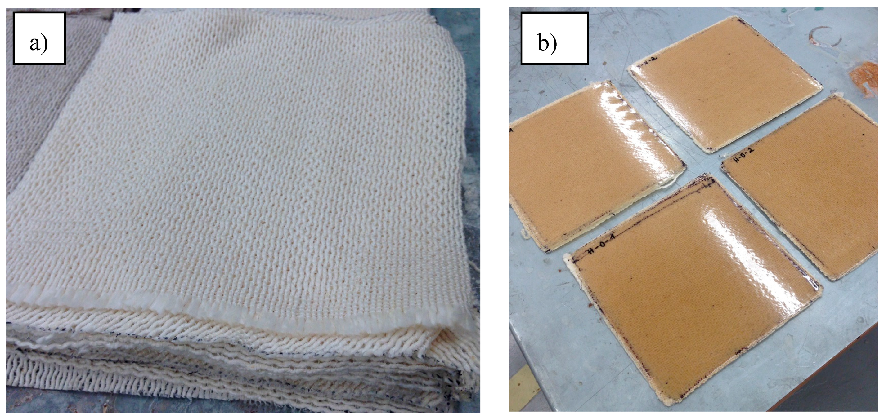
2.2.2. Fabrication of Composites

The composites were produced by compression molding, with a 20-ton manual bench press machine from Rondol Technology Ltd. (Staffordshire, UK). The hybrid yarn prepreg fabric was cut into 19 cm × 19 cm squares (Figure 1a). For each composite, 10 layers of the prepreg were used, in a 0/90-degree bidirectional lay-up. These prepregs were then put into an oven at 70 °C, to dry for at least 24 h before processing. The composites were then processed by two different methods: the experimental method (EM), where the parameters were determined during previous experiments [12] (Figure 1b), and the new method, where the parameters were determined by the FE simulation. These methods are listed in Table 2, where for the FE method a sequential pressure application is described, first with a higher value for a corresponding holding time, followed by a lower value and according holding time.
The resulting composites are called Hemp-EM and Hemp-FEM. After processing, the composites were cooled down for 10 min at room temperature, while pressuring with a weight of 12 kg, to avoid any deformation and buckling. Before testing, the specimens were conditioned for 24 h at 23 °C and 50% relative humidity, in compliance with ISO 291:2008.

2.2.3. Microscopy

An optical microscopy analysis was used to evaluate the impregnation quality of the composite samples with the different processing parameters. This was done with a Nikon SMZ800 microscope (Nikon Instruments Inc., New York, NY, USA).

2.2.4. Composite Density and Porosity

The density of the composites was determined following the hydrostatic weighing method, which is based on Archimedes’ principle [19]. Ethanol was used as the liquid medium and the composites’ densities, and the volume fractions of the fibers, matrix, and porosity were calculated, following the method by Madsen, Thygesen and Lilholt [20]. To calculate the composite density, the following Equation (1) was used:
ρ c = W a W a W l ρ l .
where Wa is the specimens’ weight in air, Wl the specimens’ weight in the liquid medium, and ρl the liquid medium’s density, here ethanol. The volume fractions of fibers (Vf), matrix (Vm) and porosity (Vp) were calculated according to Equations (2)–(4):
V f = ρ c ρ f W f .
V m = ρ c ρ m W m
V p = 1 ( V f + V m )
where ρf and ρm are the density of fibers and matrix respectively, and Wf and Wm the weight fraction of fibers and matrix in the composites.

2.2.5. Mechanical Testing

Tensile testing was done according to ISO 527:2012, with the H10KT universal testing machine from Tinius Olsen Ltd. (Salford, UK). A 5 kN load cell was used; the tests were done with a loading rate of 10 mm/min and a gauge length of 34 mm. For each composite, at least five specimens were tested, which were cut into dumbbell shapes with a total length of 150 mm. At the wider part, the specimens measured 20 mm, at the narrow part, which had a length of 60 mm, the width was 10 mm.
Charpy impact testing was done with un-notched specimens in the flatwise direction, according to the standard ISO 179:2010. This test was performed with a QC-639L pendulum impact testing machine by Cometech Testing Machines Co., Ltd. (Taichung City, Taiwan). 10 rectangular specimens for each composite were tested in the flatwise direction, which had a width of 10 mm, a length of 80 mm and varying thicknesses, according to the different processing methods.

3. Results and Discussion

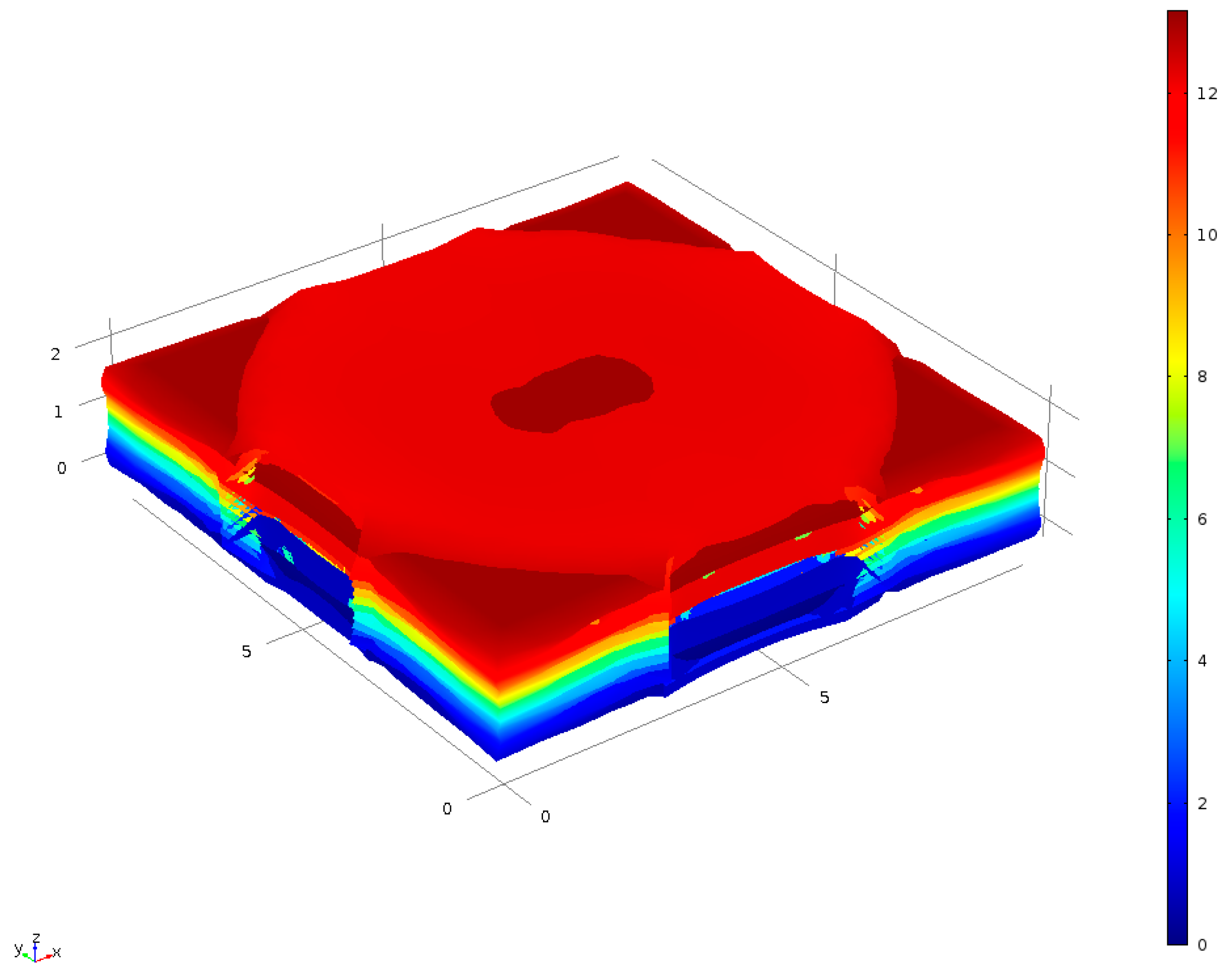
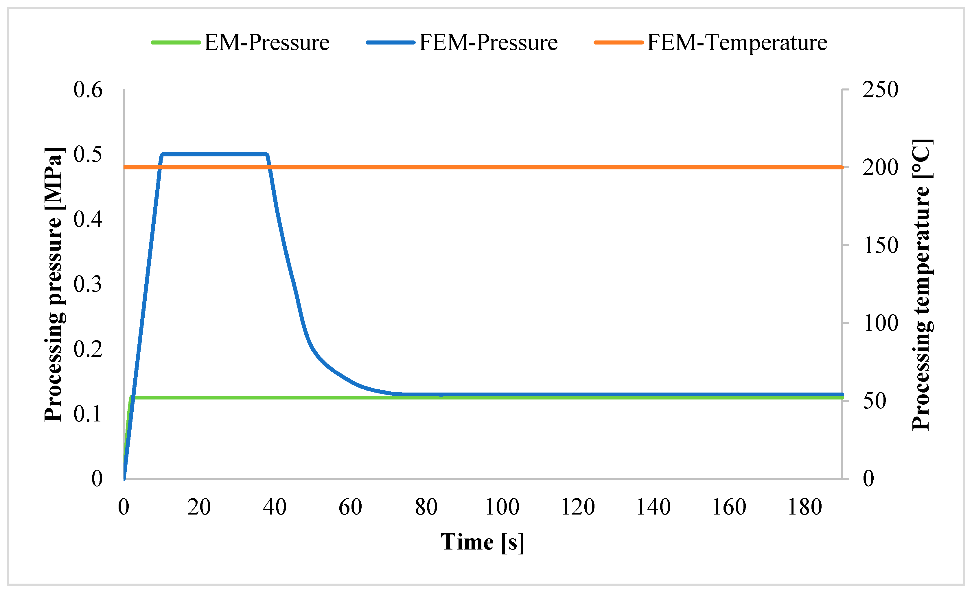
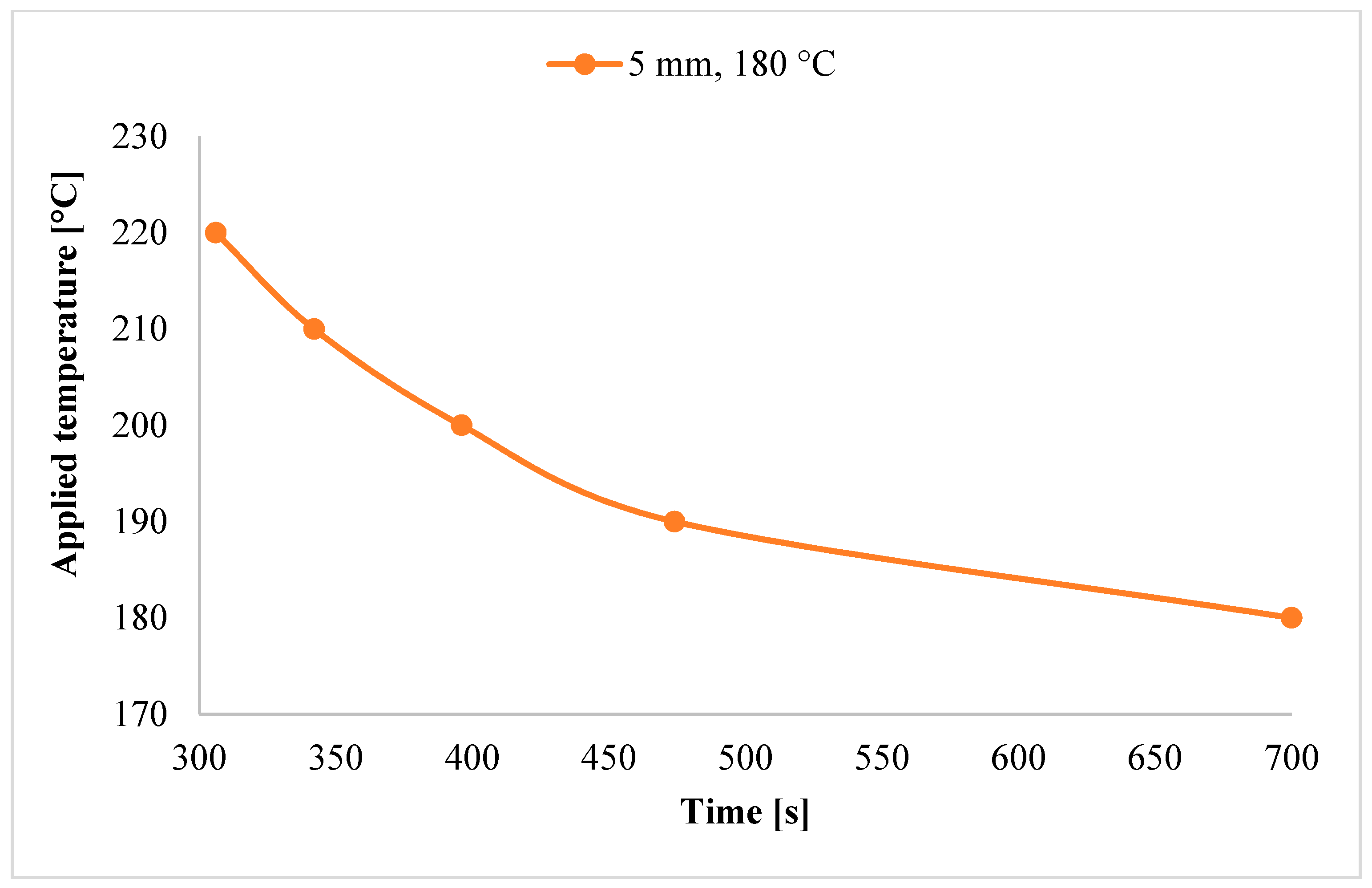
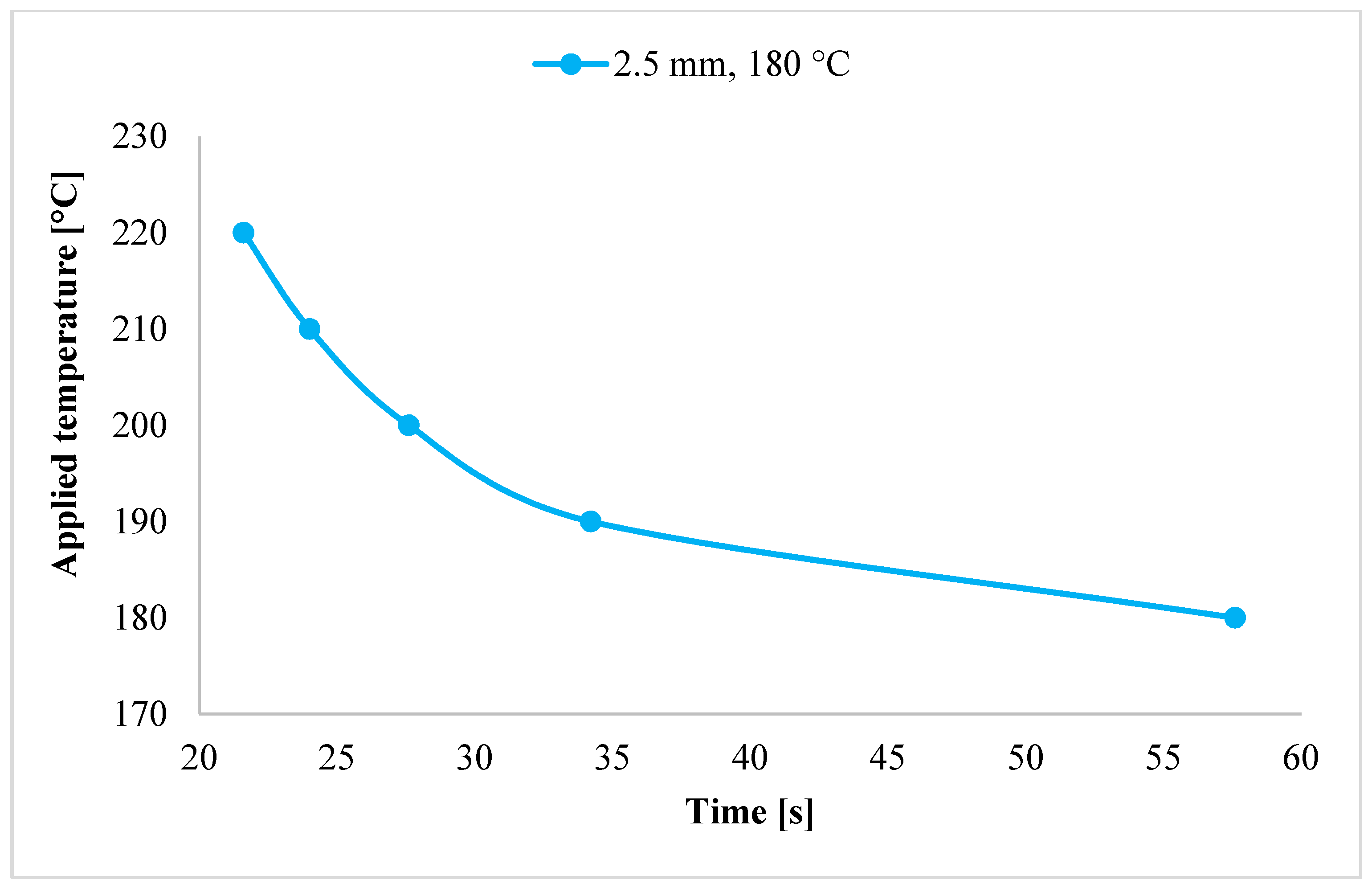
3.1. Determination of Processing Parameters with FEM
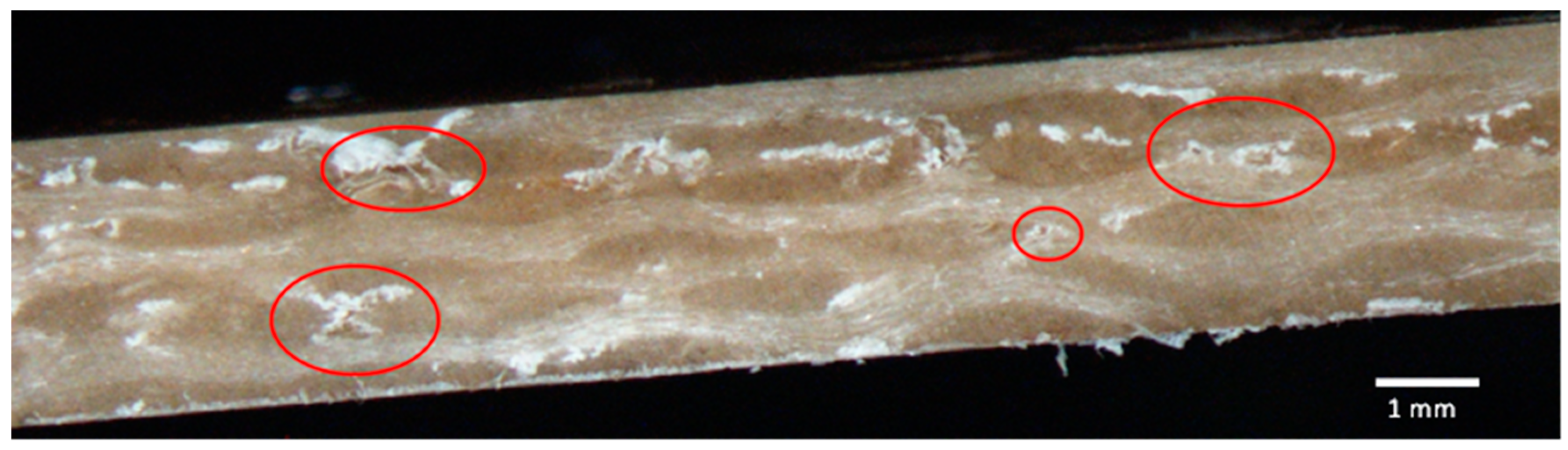
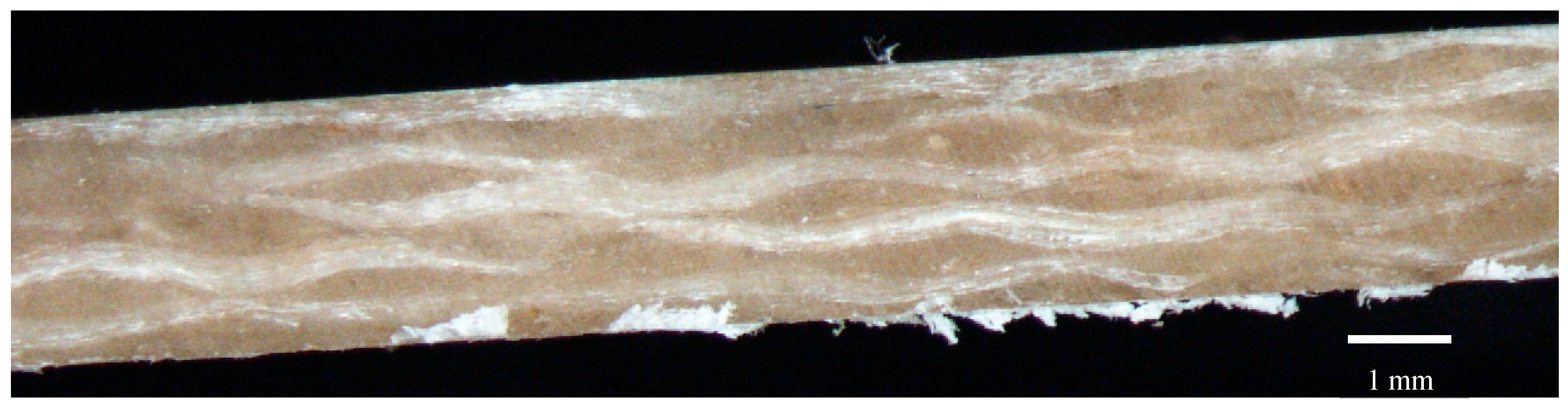
The processing parameters pressure, temperature, and time for the compression molding of the hybrid yarn prepregs are determined individually by using finite elements simulation. The parameters need to be well coordinated with each other and a few conditions need to be fulfilled. The value for the processing pressure needs to be sufficient to press out the air content in the composite lay-up and significantly reduce the thickness of the composite. It needs to compact the structure well, to reduce any gaps within, which minimizes the chance of void formation. At the same time, the pressure value should not be too high. This could lead to a deformation of the reinforcing fibers and would press the fibers towards the composite’s surfaces, leading to a stress concentration on these fibers and therefore lowering the mechanical properties. A simulation with different pressure values with material parameters for a processing temperature of 190 °C showed that a pressure of 0.13 MPa is necessary to reach a good compression result and completely remove the air content of the composite. However, during the simulations, the PLA’s Young’s modulus showed to be the deciding material property for the compression process. As previous research showed [21] this property is highly dependent on the temperature, with a large reduction in stiffness when reaching the rubbery and then the molten state. Therefore, the actual temperature at the center of the composite lay-up was determined experimentally for the beginning of the compression process and was found to be 100 °C. With an adaption of the Young’s modulus to this temperature, the simulation resulted in a necessary pressure of 0.5 MPa to reach the desired thickness of 2.5 mm. This simulation result is shown in Figure 2.
The processing temperature needs to be high enough to be able to melt the thermoplastic PLA material and to enable a relatively quick heat transfer throughout the whole structure. It should also be sufficiently high to decrease the viscosity of the molten thermoplastic, in order to facilitate the impregnation process. But, simultaneously, the value for the temperature should not be too high, so that the matrix does not become too fluid, which would make a controlled matrix flow more difficult. Finally, the possible temperature is dependent on the thermal degradation temperature of the natural fibers. As suggested in the literature, the maximum processing temperature for natural cellulose-based fibers lies around 200 °C [22]. Research has shown that above that temperature, effects of thermal degradation can be seen, which decrease the mechanical properties of the composite [23]. But, as discussed in a study by Kim and Park [3], the thermal degradation is dependent on both temperature and time. This means that an elevated processing temperature could be acceptable if applied for only a short amount of time. It becomes apparent that the time parameter needs to be well coordinated with the other values. Generally, it is preferable to keep the processing time as short as possible, to reduce the cycle times and increase the efficiency of a production process [24].
To determine the parameters of temperature and time, a heat transfer throughout the composite lay-up was simulated with different amounts of compression, to compare the time it would take for a uniform temperature distribution. The results are illustrated in the following graphs (Figure 3 and Figure 4), where it shows the time in seconds to reach 180 °C while applying temperatures between 180 °C and 220 °C.
These results emphasize the effect the thickness of the structure has on the heat transfer. For the 5-mm model, it took several minutes to reach either temperature, even with elevated temperature applications. By reducing the thickness in half, the heat transfer could complete a lot quicker. It took less than one minute in each case, even less than 30 s if the applied temperature exceeded 190 °C. This confirms that a quick compression to 2.5 mm in the beginning of the compression molding can be useful to greatly speed up the process. These temperature simulations show that there is not just a single optimal value for the processing temperature, but a range of possibilities, depending on how much time the heat transfer process should preferably take. For the present work, an applied temperature of 200 °C was selected, which would need only 28 s for the heat transfer, with a compression to 2.5 mm, due to a pressure of 0.5 MPa. This temperature was chosen, as it is able to speed up the heat transfer and consequent impregnation process significantly, while still being appropriate for processing natural fibers, without the risk of thermal degradation.
After the matrix component has completely reached 180 °C, the pressure application needs to be reduced, in order to not damage the composite and force the fibers towards the outside. Due to the temperature dependency of the PLA’s Young’s modulus [21], this value needs to be adapted for the increased temperature inside the composite. Therefore, the processing conditions from the first pressure simulations need to be reemployed, using a pressure of 0.13 MPa. The holding time for this was determined during experimental verification of the simulation results. This showed that after 2 min the internal pressure was stabilized, and there was no need for further adjustment of the pressure application. An additional 30 s was added to ensure a good distribution and impregnation of the matrix and fibers. The simulation of the compression molding with the FEM resulted in processing parameters, which should lead to an optimal consolidation result for the current hybrid yarn thermoplastic composites (see Table 2).
These parameters are illustrated in the graph in Figure 5, showing the varying pressure values while the temperature is kept at a constant value. For comparison purposes, the constant pressure value used for the experimental method (EM), for a duration of 10 min, is also included in this graph.
This shows that the main difference between the methods is a much higher pressure application during the first 30 s with the FEM, before reducing the pressure for the remaining processing time. This allows for a much quicker processing cycle, vastly reducing the time from 10 min with the experimental method, to only 3 min with the FEM.

3.2. Microscopy

A microscopic analysis of the composites produced with the experimental method and with the FEM shows clearly different results obtained with the different methods. These can be seen in the following Figure 6 and Figure 7.
In Figure 6, showing the composite produced with the experimental method, several voids of different dimensions can clearly be seen. These are mostly present at the interface between the reinforcement and matrix, showing a flawed interfacial adhesion. In addition to that, several dry areas are visible, indicating an unsatisfactory impregnation result. This result suggests that the experimental method is not optimal for this hybrid yarn fabric, possibly negatively impacting the composite’s mechanical properties due to insufficient consolidation and impregnation results. Figure 7, on the other hand, displays the composite produced with the FEM. An improved consolidation result is apparent, showing no definite voids at the fiber-matrix interface. This result suggests that the FEM’s parameters are suited to improve the interfacial adhesion and the overall consolidation result, possibly resulting in superior mechanical properties.

3.3. Composite Density and Porosity

The composites’ densities and the volume fractions of fibers, matrix, and porosity were determined according to Equations (1)–(4). The average values for each fabrication method are listed in Table 3.
These results show only small differences in the volume fractions, with slightly increased fiber and matrix volume fractions for the FEM composite, while the porosity volume fraction decreases. While it is only a minor difference, an improvement can be seen for the composite produced with the FEM. This could suggest improved mechanical properties for this composite. The decrease in porosity might be due to the increased pressure values used with the FEM, that effectively and quickly eliminated the air content from the composites. Additionally, this could have improved the fiber impregnation process, since the flow distance was considerably decreased throughout the whole compression molding, by immediately compressing the lay-up to 2.5 mm. Also, the slightly higher temperature might have added to an improved and faster impregnation process, by ensuring a completely molten PLA, and therefore easier flow, resulting in lower porosity content. The results obtained with this test, however, show a much smaller difference than the microscopic images. This could suggest a non-uniform impregnation result for both composites, with different impregnation qualities in different areas of the composites. This would indicate that the processing method determined with the FEM is not the optimal method yet. While it is able to lead to some improvements, there might still be room for further improvement.

3.4. Tensile Properties

The results of the tensile test are shown in Table 4, which displays the average tensile strength and modulus, as well as the standard deviations, of the composites produced with the two different methods. It shows a minor increase in tensile strength with the FEM, from 49.52 MPa to 51.36 MPa. A slightly larger increase in tensile modulus can be seen, from 12 GPa to 13 GPa. With an increased modulus, the elongation at break properties decreased accordingly, from 0.79% to 0.66%, indicating a stiffer composite with the FEM.
The increase in both tensile strength and modulus with the FEM indicates an enhanced interfacial adhesion and improved overall impregnation result with the application of the FEM.

3.5. Impact Properties

The results from the impact test are shown in Table 4, with the average impact strength, as well as the standard deviations, for each method. An increase in impact strength can be seen again for the FEM composite. The Hemp-EM composite reached an impact strength of 15.09 kJ/m2, the Hemp-FEM composite of 16.56 kJ/m2. Also for this test, the difference in properties between the methods is relatively small, but, again an increase can be seen with the FEM, which is in agreement with all other test results.
The impact strength results are rather low, which is as expected for hemp composites. This is in agreement with other studies that showed that hemp composites possess a rather low potential for energy absorption upon impact, decreasing the values of neat PLA samples [25]. The impact strength is directly related to the elongation at break properties, with higher elongations leading to higher impact strengths. It is therefore not surprising that the hemp composites do not possess high impact strengths, as these composites proved to be very stiff. The impact strength was, however, improved with the FEM, while the elongation at break properties showed a decrease during the tensile test. This increase in impact strength might be due to improved consolidation results and lower porosity contents.

4. Conclusions

The simulation of thermoplastic composites using the FEM was able to give valid information about processing parameters for compression molding, and their effect on the materials involved, making it possible to draw conclusions about processing conditions and final composite product properties. The simulations applied in this study resulted in adequate values for the processing temperature, pressure, and time, leading to good composite results. The resulting composite plates showed a good impregnation with completely matrix-covered surfaces and thicknesses in the desired dimensions. With the simulations, it was possible to reduce the time component substantially, from the initial 10 min determined through experimental work, to a mere 3 min. It was found that the actual heat transfer can be completed in a matter of seconds if the right conditions are established. This result alone proves the beneficial character of the simulation of composites, as a reduced processing time is highly preferable for industrial production and renders a more competitive product. The findings from the experimental analysis suggest a trend for improvement in mechanical properties with the FEM, due to a better impregnation result. These improvements were just minor differences though, not resulting in significantly higher mechanical properties. This suggests that the current study can be seen as a constructive step towards increasing mechanical properties for these biocomposites, but shows that there is room for further improvement. In order to accurately simulate the reality, the FE simulation, as well as the experimental work, has to be set up even more precisely.
Overall, this study demonstrates the suitability of finite element simulation for the production of biocomposites. It showed that it is possible to closely simulate the process, giving useful information about the material behavior and process parameters. This could save a lot of time and material in the industrial production of composites, and therefore be of high economical use. By making use of simulations, the need for preliminary experimental tests is reduced considerably, minimizing the amount of wasted materials for samples. Also, the reduced amount of time is substantial, as the process cycle times can be condensed greatly, by determining the most efficient processing conditions through simulations. In combination with the use of environmentally friendly materials, this has the potential of greatly benefiting the long-term sustainability of composites in a wide range of areas, from automobile to construction applications.

Author Contributions

Behnaz Baghaei, Sarah Vogt, Mikael Skrifvars and Nawar Kadi conceived and designed the experiments; Sarah Vogt performed the experiments; Sarah Vogt analyzed the data; Sarah Vogt wrote the paper.

Conflicts of Interest

The authors declare no conflict of interest.

References

  1. Sawpan, M.A.; Pickering, K.L.; Fernyhough, A. Improvement of mechanical performance of industrial hemp fibre reinforced polylactide biocomposites. Compos. Part A Appl. Sci. Manuf. 2011, 42, 310–319. [Google Scholar] [CrossRef]
  2. Thakur, V.K.; Thakur, M.K.; Gupta, R.K. Review: Raw natural fiber–based polymer composites. Int. J. Polym. Anal. Charact. 2014, 19, 256–271. [Google Scholar] [CrossRef]
  3. Kim, S.H.; Park, C.H. Direct impregnation of thermoplastic melt into flax textile reinforcement for semi-structural composite parts. Ind. Crops Prod. 2017, 95, 651–663. [Google Scholar] [CrossRef]
  4. Kandar, M.I.M.; Akil, H.M. Application of design of experiment (DoE) for parameters optimization in compression moulding for flax reinforced biocomposites. Procedia Chem. 2016, 19, 433–440. [Google Scholar] [CrossRef]
  5. Graupner, N.; Herrmann, A.S.; Müssig, J. Natural and man-made cellulose fibre-reinforced poly(lactic acid) (PLA) composites: An overview about mechanical characteristics and application areas. Compos. Part A Appl. Sci. Manuf. 2009, 40, 810–821. [Google Scholar] [CrossRef]
  6. Masirek, R.; Kulinski, Z.; Chionna, D.; Piorkowska, E.; Pracella, M. Composites of poly(L-lactide) with hemp fibers: Morphology and thermal and mechanical properties. J. Appl. Polym. Sci. 2007, 105, 255–268. [Google Scholar] [CrossRef]
  7. Pickering, K.L.; Aruan Efendy, M.G. Preparation and mechanical properties of novel bio-composite made of dynamically sheet formed discontinuous harakeke and hemp fibre mat reinforced PLA composites for structural applications. Ind. Crops Prod. 2016, 84, 139–150. [Google Scholar] [CrossRef]
  8. Baghaei, B.; Skrifvars, M.; Salehi, M.; Bashir, T.; Rissanenm, M.; Nousiainen, P. Novel aligned hemp fibre reinforcement for structural biocomposites: Porosity, water absorption, mechanical performances and viscoelastic behaviour. Compos. Part A Appl. Sci. Manuf. 2014, 61, 1–12. [Google Scholar] [CrossRef]
  9. Baghaei, B.; Skrifvars, M. Characterisation of polylactic acid biocomposites made from prepregs composed of woven polylactic acid/hemp—Lyocell hybrid yarn fabrics. Compos. Part A Appl. Sci. Manuf. 2016, 81, 139–144. [Google Scholar] [CrossRef]
  10. Baghaei, B.; Skrifvars, M.; Berglin, L. Manufacture and characterisation of thermoplastic composites made from PLA/hemp co-wrapped hybrid yarn prepregs. Compos. Part A Appl. Sci. Manuf. 2013, 50, 93–101. [Google Scholar] [CrossRef]
  11. Baghaei, B.; Skrifvars, M.; Rissanen, M.; Ramamoorthy, S.K. Mechanical and thermal characterization of compression moulded polylactic acid natural fiber composites reinforced with hemp and lyocell fibers. J. Appl. Polym. Sci. 2014, 131, 1–10. [Google Scholar] [CrossRef]
  12. Baghaei, B.; Skrifvars, M.; Berglin, L. Characterization of thermoplastic natural fibre composites made from woven hybrid yarn prepregs with different weave pattern. Compos. Part A Appl. Sci. Manuf. 2015, 76, 154–161. [Google Scholar] [CrossRef]
  13. Baghaei, B. Development of Thermoplastic Biocomposites Based on Aligned Hybrid Yarns for Fast Composite Manufacturing. Ph.D. Thesis, University of Borås, Borås, Sweden, 2015. [Google Scholar]
  14. Bruno, A.D.; Baskaran, M. Analysing the mechanical properties of natural fiber reinforced polymer composites using FEA. Int. J. Eng. Sci. Res. Technol. 2014, 3, 269–282. [Google Scholar]
  15. Yu, Z.-C.; Townsley, M.; McKay, S. Natural fiber composites for mass transportation industry. In Proceedings of the 26th Annual Technical Conference of the American Society for Composites 2011: The 2nd Joint US-Canada Conference on Composites, Montreal, QC, Canada, 26–28 September 2011; Hyer, M., Ed.; Destech Publications: Lancaster, PA, USA, 2011. [Google Scholar]
  16. Henton, D.E.; Gruber, P.; Lunt, J.; Randall, J. Polylactic acid technology. In Natural Fibers, Biopolymers, and Biocomposites; CRC Press Inc. M.U.A.: Boca Raton, FL, USA, 2005. [Google Scholar]
  17. GreenSpec. Insulation Materials and Their Thermal Properties; GreenSpec: Groningen, The Netherlands, 2017. [Google Scholar]
  18. Jamshidian, M.; Tehrany, E.A.; Imran, M.; Jacquot, M.; Desobry, S. Poly-lactic acid: Production, applications, nanocomposites, and release studies. Compr. Rev. Food Sci. Food Saf. 2010, 9, 552–571. [Google Scholar] [CrossRef]
  19. Pratten, N.A. The precise measurement of the density of small samples. J. Mater. Sci. 1981, 16, 1737–1747. [Google Scholar] [CrossRef]
  20. Madsen, B.; Thygesen, A.; Lilholt, H. Plant fibre composites—Porosity and volumetric interaction. Compos. Sci. Technol. 2007, 67, 1584–1600. [Google Scholar] [CrossRef]
  21. Zhou, C.; Guo, H.; Li, J.; Huang, S.; Li, H.; Meng, Y.; Yu, D.; Christiansen, J.C.; Jiang, S. Temperature dependence of poly(lactic acid) mechanical properties. RSC Adv. 2016, 6, 113762–113772. [Google Scholar] [CrossRef]
  22. La Mantia, F.P.; Morreale, M. Green composites: A brief review. Compos. Part A Appl. Sci. Manuf. 2011, 42, 579–588. [Google Scholar] [CrossRef]
  23. Bismarck, A.; Mishra, S.; Lampke, T. Plant fibers as reinforcement for green composites. In Natural Fibers, Biopolymers, and Biocomposites; CRC Press Inc. M.U.A.: Boca Raton, FL, USA, 2005; pp. 36–112. [Google Scholar]
  24. Tatara, R.A. Compression molding. In Applied Plastics Engineering Handbook, 2nd ed.; Kutz, M., Ed.; William Andrew Publishing: Oxford, UK, 2017; pp. 291–320. [Google Scholar]
  25. Graupner, N. Improvement of the mechanical properties of biodegradable hemp fiber reinforced poly(lactic acid) (PLA) composites by the admixture of man-made cellulose fibers. J. Compos. Mater. 2009, 43, 689–702. [Google Scholar] [CrossRef]
Figure 1. (a) The hybrid yarn warp-knitted prepreg fabric and (b) the manufactured composites.
Jcs 02 00011 g001
Figure 2. Simulation of pressure parameter: displacement to 2.5 mm with the PLA’s Young’s modulus at 100 °C and a pressure application of 0.5 MPa, displacement shown in mm.
Jcs 02 00011 g002
Figure 3. Time to complete a heat transfer of 180 °C, with differing applied temperatures, for a composite thickness of 5 mm.
Jcs 02 00011 g003
Figure 4. Time to complete a heat transfer of 180 °C, with differing applied temperatures, for a composite thickness of 2.5 mm.
Jcs 02 00011 g004
Figure 5. Processing values for pressure, temperature, and time determined with the FEM, compared with the pressure value for EM.
Jcs 02 00011 g005
Figure 6. Microscopical picture of the Hemp-EM composite with several voids at the fiber-matrix interface, marked in red.
Jcs 02 00011 g006
Figure 7. Microscopical picture of the Hemp-FEM composite with improved interfacial adhesion and no definite voids.
Jcs 02 00011 g007
Table 1. Material properties for the FE simulation.
HempPLA
Density ρ1.480 g/cm3 [13]1.240 g/cm3 [13]
Young’s modulus E14.00 GPa [13]2.91 GPa at 22 °C [13]
Poisson’s ratio ν0.221 [14]0.360 [13]
Coefficient of thermal
expansion α
10−6 1/°C [15]7.4 × 10⁻⁴ 1/°C [16]
Heat capacity at constant pressure Cp2000 J/(kg × K) [17]2060 J/(kg × °C) at 190 °C [18]
Thermal conductivity λ0.040 W/(m × K) [17]0.195 W/(m × °C) at 190 °C [18]
Table 2. Processing methods for the composite fabrication.
Temperature Pressure Time
Experimental method190 °C0.125 MPa10 min
FE method200 °C0.5 MPa28 s
0.13 MPa2.5 min
Table 3. Composition of hemp/PLA composites, fabricated with the two different methods.
Composite Density ρc [g/cm3]Fiber Volume Fraction Vf [%]Matrix Volume Fraction Vm [%]Porosity Volume Fraction Vp [%]
Hemp-EM1.2834.5861.903.52
Hemp-FEM1.2834.6261.993.39
Table 4. E-modulus, tensile and impact strength of the different hemp/PLA composites.
Tensile Strength [MPa]E-Modulus [GPa]Impact Strength [KJ/m2]
Hemp-EM49.52 (1.50)14.29 (2.91)15.09 (1.25)
Hemp-FEM51.36 (2.34)24.05 (6.11)16.56 (2.12)

