On the Convergence of Laminated Composite Plates of Arbitrary Shape through Finite Element Models


1
DICAM Department, University of Bologna, 40136 Bologna, Italy
2
Department of Mechanical Engineering, University of Porto, 4200-465 Porto, Portugal
*
Author to whom correspondence should be addressed.
J. Compos. Sci. 2018, 2(1), 16; https://doi.org/10.3390/jcs2010016
Submission received: 15 February 2018
/
Revised: 2 March 2018
/
Accepted: 12 March 2018
/
Published: 14 March 2018
(This article belongs to the Special Issue Advanced Composite Materials Applied to Structural Mechanics)
Abstract
:The present work considers a computational study on laminated composite plates by using a linear theory for moderately thick structures. The present problem is solved numerically because analytical solutions cannot be found for such plates when lamination schemes are general and when all the stiffness constants are activated at the constitutive level. Strong and weak formulations are used to solve the present problem and several comparisons are given. The strong form is dealt with using the so-called Strong Formulation Finite Element Method (SFEM) and the weak form is solved using commercial Finite Element (FE) packages. Both techniques are based on the domain decomposition technique according to geometric discontinuities. The SFEM solves the strong form inside each element and needs the implementation of kinematic and static inter-element conditions, whereas the FE solves the weak form and the continuity conditions among the elements are given in terms of displacements only. The results are reported in graphical form in terms of the first three natural frequencies. The accuracy and stability of SFEM and FE are thoroughly discussed.
1. Introduction
As it is well known, engineering theories for plates and shells simplify the three-dimensional (3D) elasticity problem by introducing the kinematic hypothesis, which leads to simpler mathematical problems. Therefore, such simplified theories have limitations that are strictly related to the initial hypotheses. The present work is based on the so-called Reissner–Mindlin theory or First-order Shear Deformation Theory, which is used to study moderately thick plates [1,2]. The term “moderately thick” refers to the fact that the plate is not “thin” as in the Classical Laminated Plate Theory (CLPT) or Kirchhoff-Love Theory and not “thick” as in the classical 3D theory of elasticity. Once the physical problem is mathematically well-posed, it is generally solved via numerical methods due to the complexity of finding analytical or semi-analytical solutions for general configurations. The present work aims to show a peculiar behavior in the solution of such problems by comparing the results obtained using strong and weak form finite element methods when the plates are in free vibrations. In particular, the authors compare the results obtained with two- and three-dimensional theories as a function of the plate thickness and material configuration, such as isotropic and laminated composite.
The free vibration problem of plates with regular shape has been developed since the XIX century. The study on vibrations of composite laminates started in the early 60s and is nowadays still a topic of great interest among researchers. In particular, plates of arbitrary shape and made of composite materials are investigated in the following article.
Rectangular plates were the first structures to be studied, because for some configurations an analytical or semi-analytical solution could be found. In 1970, Srinivas et al. [3] studied thick homogeneous and laminated plates. In 1978, Nelson [4] presented the vibration problem of rectangular plates and bars with a solution that satisfied the Mindlin equations. The same topic was presented by Ali and Atwal [5]. In 1992, Lee and Lim [6] studied squared isotropic and orthotropic plates with in-plane forces. Farsa et al. in 1993 [7,8] used the Generalized Differential Quadrature (GDQ) method for the vibration of rectangular orthotropic and anisotropic laminated plates. Coupled rectangular plates were investigated in 1996 by Bardell et al. [9]. The GDQ method was considered in 1998 by Wang et al. [10]. In 1999, Huang and Sakiyama [11] studied rectangular plates with holes of different shapes. In 2003, Karami and Malekzadeh [12] proposed a new version of the GDQ method in which multiple boundary conditions were implemented in the weighting coefficients for the derivative approximation in square and rectangular plates. In the same year, Liew et al. [13,14] used the Ritz method and the FSDT for studying laminated rectangular plates with central holes. In 2004, Huang and Li [15] studied the flexural strength of plates with anti-symmetrical lamination schemes. Seok et al. [16] presented the out-of-plane motions of cantilevered rectangular plates. In 2006, Singh and Tanveer [17] investigated multi-connected rectangular plates in several configurations. In 2007, Shu et al. [18] used the finite difference method based on the least squares, for the free vibration problems of thin isotropic plates of general shape. Among all, square plates with semi-circular cut-outs were considered. In 2008, Houmat [19] studied the free vibration problem of plates with curvilinear edges and square plates with holes. In the same year, Secgin and Sarigul [20] used the Discrete Singular Convolution (DSC) method for the free vibration of square plates. Quadrilateral plates were studied with a Fringing meshfree interpolation technique by Bui et al. [21]. In 2011 and 2012, Dozio and Carrera [22,23] presented the free vibration problem of quadrilateral plates with various thicknesses and different plate theories. A modified version of the Differential Quadrature (DQ) method was proposed by Eftekhari and Jafari in 2013 [24] for rectangular plates with several boundary conditions. Quadrilateral plates were studied using the DQ method also by Nassar et al. [25]. In 2014, Kurtaran [26] investigated the effect of element shape on the free vibrations of plates made of Functionally Graded Materials (FGMs) [27,28,29,30,31,32,33,34,35]. Finally, Kumar et al. [36] have recently proposed laboratory tests and theoretical analyses for the free vibrations of composite laminated plates made of glass/epoxy.
When the plate is not of regular shape, numerical or complex analytical approaches should be considered. However, due to the geometric distortion, the accuracy of a methodology might be lower than others according to the applied distortion. The free vibration problem of skew plates was first studied by Claasen [37] in 1963. Nair and Durvasula [38] in 1973 and Mizusawa et al. [39] in 1979 also studied the same problem. In 1980, Kanaka Raju and Hinton [40] and in 1988, Gorman [41] studied simply-supported and fully clamped skew plates. The finite element method was used by Bardell in 1992 [42] for the free vibration problem of skew plates and analogous studies were conducted by Liew and Wang [43] in 1993. Several geometries, with skew plates with different skew angles, were studied using the DQ method by Bert and Malik in 1996 [44] and Hosokawa et al. [45] in the same year. Han and Dickinson [46] proposed the study of skew plates with symmetric lamination schemes. Wang [47,48] published a similar study using the First-order Shear Deformation Theory (FSDT). A shear-deformable finite element was used for the free vibration problem of skew plates by Sheikh et al. [49] in 2002. In 2003, Karami and Malekzadeh [50,51] implemented a DQ technique for quadrilateral plates with straight edges of skew and trapezoidal shape. The FSDT was considered by Liew et al. [52] for investigating the skew plate strength. Garg et al. [53] studied skew plates with laminated and sandwich configurations. In 2008, several studies were published on skew plates by Civalek [54], Das et al. [55], Nallim and Oller [56], and Zhou and Zheng [57]. Ashour [58] focused his research on skew plates symmetrically clamped and Gurses et al. [59] presented skew plates studied with FSDT. In 2012, Rao and Babu [60] presented thin skew plates symmetrically laminated with holes. Skew plates, made of composite materials, were studied by Dozio and Carrera [22,23] and also by Srinivasa et al. [61]. The DQ method was used for studying skew plates with free edges by Wang and Wu [62]. Other studies were presented by Kurtaran [26], Zhang and Xiao [63], Zhang [64] and Wang et al. [65]. Finally, Mohazzab and Dozio [66] presented a study on skew plates in 2015.
Circular, annular, and sectorial plates have been thoroughly studied in the last 40 years. First studies were conducted by Ramakrishnan and Kunukasseril [67] in 1976. Irie et al. [68,69] published two works on orthotropic circular plates with simply-supported edges. Clamped circular plates were presented by Maruyama and Ichinomiya [70]. Srinivasan and Thiruvenkatachari [71,72] treated the problem of annular isotropic plates in free vibrations for the first time. An analytical solution for sectorial plates was presented by Harik and Molaghasemi [73] in 1989. Sectorial plates were analyzed by Misuzawa and Kajita [74], whereas annular plates were considered by Misuzawa and Takami [75]. In the same topic, other researchers focused their studies using different techniques such as Liew and Lam [76] and Xiang et al. [77]. In 1995, McGee et al. [78,79] presented two papers on annular plates with several boundary conditions, as well as Bert and Malik in 1996 [44]. Circular Mindlin plates (with and without discontinuities) were investigated by Liew et al. and Liu et al. [80,81,82,83,84] using the DQ method. In 2002, Zhong [85] applied the triangular DQ method to sectorial plates using a curvilinear mapping for triangular elements. In 2003, Civalek and Catal [86] used the HDQ method for linear static and free vibration problems of annular and circular plates. Between 2003 and 2004 Liew et al. [14,52,87] published several papers on sectorial and annular plates with the DQ method. The buckling and vibration of sectorial plates was investigated by Sharma et al. [88]. Similarly, Nie and Zhong [89] and Shu et al. [18] presented other studies on circular plates. In 2008, Dong [90] presented a three-dimensional analysis of annular plates in free vibrations. Several papers about sectorial and annular plates were presented by Civalek [91,92], Xing and Liu [93], and Zhou et al. [94]. Civalek and Ozturk [95] studied the free vibrations of sectorial plates using a quadrilateral finite element with curvilinear edges. Finally, plates with curvilinear edges were studied by Kurtaran [26].
The most difficult geometries to treat in numerical analysis are the triangular and trapezoidal shapes, due to their geometry, which can lead to strong shape distortion. Triangular isotropic and orthotropic plates were studied for the first time by Lam et al. [96] in 1990 and by Dubliner [97] in 1991. Triangular isosceles plates were investigated by Kitipornchai et al. [98] and partially supported plates were presented by Mirza and Alizadeh [99], whereas cantilever plates of triangular and trapezoidal shape were illustrated by Qatu [100]. In 1996, Abrate [101] and Karunasena et al. [102] studied simply-supported triangular plates. Singh and Saxena [103], Karunasena and Kitipornchai [104], and Singh and Hassan [105] investigated triangular plates with variable thicknesses. In 2000, Sakiyama and Huang [106] dedicated their studies to triangular plates of variable thickness and in the same year Zhong [107] presented isosceles plates with the DQ method. Sheikh et al. [108] showed a shear-deformable finite element for laminated composite plates of several shapes. Trapezoidal plates were presented by Karami and Malekzadeh [50] and Karami et al. [51]. The previously cited Shu et al. [18] also studied trapezoidal plates with the finite differences method based on the least squares. The same for Civalek [54] in 2008, who also presented trapezoidal plates. Plates of trapezoidal shape were presented by Nallim and Oller [56] and Civalek and Gurses [109]. Thick trapezoidal plates were deeply studied by El-Sayad and Ghazy [110], Quintana and Nallim [111], and Rango et al. [112,113].
Other plates of complex shape are elliptic plates, pentagonal, heptagonal, and plates with holes. The free vibrations of elliptic plates were presented by Singh and Chakraverty [114] in 1992, followed by Bert and Malik [44] in 1996. Not-homogeneous elliptic plates were presented by Chakraverty et al. [115] in 2005 and the DQ method was used by Xing and Liu [93], and Civalek and Ozturk [95]. Elliptic laminated plates were presented by Bui et al. [21] and Kurtaran [26].
Pentagonal and heptagonal plates were not investigated much in the past. Some studies by Ghazi et al. [116] and Xing and Liu [93] must be mentioned.
Complex analysis is carried out for plates with holes due to the strong geometric discontinuity, rather than the geometric distortion. Plates with holes were presented by Lim and Liew in 1995 [117]. Plates with holes were also considered by Houmat [19] and Liu et al. [118]. In 2011, Bui et al. [21] studied laminated plates in free vibrations with openings. Moreover, laminated pierced plates were presented by Rao and Babu [60] and recently by Rango et al. [112,113].
Other studies [119,120,121,122,123,124,125,126,127,128,129,130,131,132,133,134,135,136,137,138,139,140,141,142,143,144,145,146,147,148,149,150,151,152,153,154,155,156,157,158,159,160,161,162,163,164,165,166,167,168,169,170,171,172,173,174] regarding plates made of composite materials and higher order theories are noted. They are important because they represent the background of the present work. The problem of plates can be treated with innovation. Other methods, both numerical and analytical, the interested reader can find in the list of papers given.
2. First-Order Laminated Plate Theory
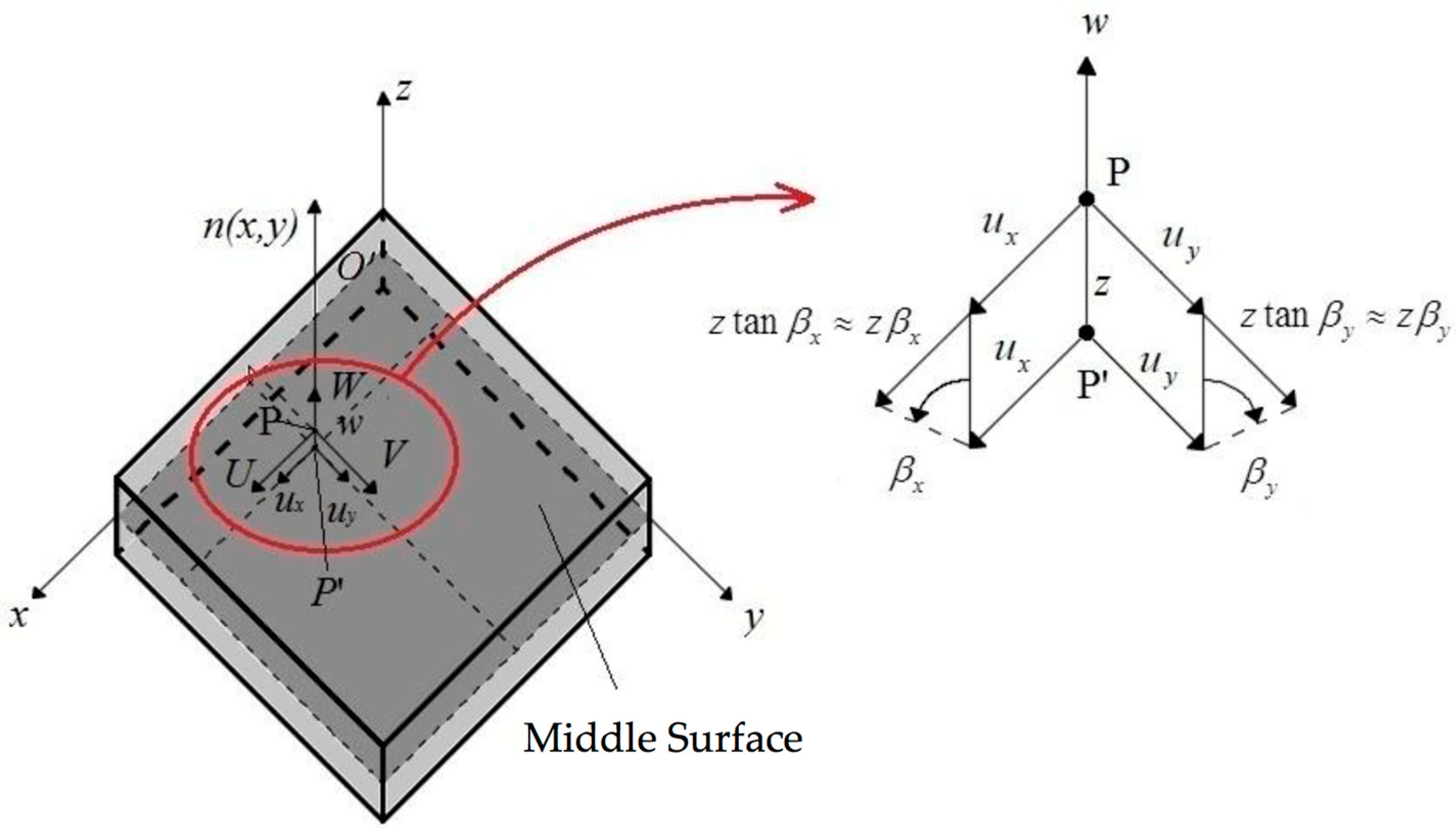
The so-called First-order Shear Deformation Theory (FSDT) or Reissner–Mindlin theory is the most common and well-known theory for studying plates and shell structures. It is not the purpose of the present work to extensively present such theory but to compare the numerical results obtained using FSDT with different approaches, in particular strong and weak formulations. Therefore, only main equations are reported in the following. According to the given hypothesis of FSDT, the displacement field considers five kinematic parameters as shortly given below
where the three-dimensional displacements are indicated with capital letters, whereas the kinematic parameters (three in-plane displacements and two rotations) with small letters. The graphical representation of the displacement field (1) is given in Figure 1.
The present theory considers eight strain characteristics on the plate middle surface instead of the three-dimensional strain tensor. Such quantities can be divided into three groups, the in-plane characteristics , the curvatures and the shear strains . The latter by definition are constant through the thickness, therefore, the present theory needs a shear correction factor for a correct approximation of the shear stresses.
Equilibrium equations are of the same number as the degree of freedom of the model and they are a function of eight stress resultants which correspond to the eight strain characteristics of the kinematic field. The present theory considers also the rotary inertia as indicated in the equilibrium equations given below.
where are the in-plane forces, represent bending moment and torque and are the shear forces which are constant through the thickness by hypothesis. The inertia terms are defined as
It is recalled that, the rotary inertias are significant when the thickness of the plate is relevant when compared to its in-plane dimensions. A graphical representation of the stress resultants is given in Figure 2.
The theory of laminated composite materials considers strain and stress components that vary ply by ply according to the following general constitutive law
It is remarked that, Equation (4) considers a general orientation of the orthotropic layers (indicated by the superscript within the stacking sequence. The stiffness constants are expressed by classical relationships that can be found in [174,175].
The constitutive equations for FSDT theory can be summarized by the following system
where the two vectors have the same meaning as aforementioned. for are the membrane, coupling and bending stiffnesses. The shear correction factor is indicated as and it is taken as .
The present study focuses on the free vibration behavior of plates as a function of the relationships given by Equation (5). For instance, when a plate made with a single isotropic ply is considered , thus, the in-plane behavior is un-coupled with the bending part, moreover . Analogously for cross-ply symmetric laminates. On the contrary, for a general lamination scheme made of orthotropic plies all the coefficients of the constitutive law are not null. In this regard, it is noted that, numerical issues occur when some of these combinations are considered as it will be discussed in the sections below.
3. Numerical Implementation
The present work deals with geometries of different shape because geometric discontinuities and distortions might be present. In particular, the authors consider a strong form finite element scheme termed SFEM (Strong Formulation Finite Element Method [176,177,178,179,180,181,182,183]) for the following simulations. Moreover, the present novel results are compared to the same solutions obtained through commercial finite element codes (Abaqus and Straus7). For the sake of conciseness and also because the SFEM implementation is not the main purpose of the present work, interested readers are invited to read reference papers for details on this numerical technique [176,177,178,179,180,181,182,183]. In a few words, SFEM is a domain decomposition technique in which the continuity among the elements is enforced in terms of displacements and stresses and the solution is sought in the strong form. The advantage of the strong formulation is that no integration is required and the solution is carried out by simply discretizing the fundamental system of equations in terms of displacements. External boundary conditions consider both kinematic and static conditions due to the strong form nature of the problem. In general, domain decomposition methods consider also domains of general shape. However, functions can be integrated or derived in regular (square) domains only, therefore, a mapping technique is introduced. In conclusion, the SFEM is used to select basis functions and the type of grid point collocation for the numerical approximation among each finite element. In addition, the number of domain divisions and the number of collocation points for each element must be defined. The combination of these four parameters changes the accuracy and reliability of the SFEM formulation. On the contrary, classical FE considers element shape functions as element basis functions (with 4 or 8 nodes) and Gauss integration with Gauss–Legendre points are for the evaluation of the elemental integrals. In conclusion, the approximation at the element level is a variable in the SFEM, whereas classic FE considers low order polynomials (linear or quadratic) for the same approximation.
As far as the SFEM is concerned, the Lagrange basis is selected as the basis function and the Chebyshev–Gauss–Lobatto grid has been considered. Such a selection leads to good and convergent results for any number of grid points and domain divisions [176]. Therefore, the present choice is preferable for studying plates made of composite materials. For the element mapping, both classical serendipity mapping and NURBS-based mapping have been considered [176,177,178,179,180,181,182,183]. All the provided simulations have been carried out through the Differential Quadrature for Mechanics of Anisotropic Shells, Plates, Arches, and Beams (DiQuMASPAB) software [184], which implements the SFEM in a user-friendly interface.
4. Applications
In the present section, some numerical applications are provided regarding both isotropic and laminated composite plates of arbitrary shape. Since most of the references present the solution of only rectangular (or square) plates, the authors want to point out the accuracy and stability of the present numerical techniques for arbitrarily shaped plates only. In particular, skew, circular and elliptic plates are studied. The solutions are provided by increasing the degrees of freedom of each model for a fixed geometry and on the same geometry. The plate thickness is increased in order to find the validity limit of the FSDT theory in terms of natural frequencies.
The number of grid points along the two main directions for each reference domain in the SFEM are equal as in standard FE [172]. Thus, the SFEM considers a different number of finite elements and of grid points inside each element. In the FE models, the number of finite elements is variable and the number of points for the approximation for each domain considered linear or quadratic shape functions. Both techniques consider fixed basis functions and type of point collocation. The SFEM simulations are indicated as SFEMn-CGL, where n indicates the number of finite elements used in the mesh, whereas the number of grid points per domain are indicated by N. The Straus7 elements are: triangular shape as Tri3 and Tri6. The former is a triangle with four nodes and the latter is a triangle with six nodes. The quadrilateral Straus7 elements are: Quad4, Quad8 and Quad9 with four, eight and nine nodes, respectively. Abaqus elements are also triangular and quadrilateral as: S3, STRI65 (three and six nodes) and S4, S4R, S8R, S8R5. The first number identifies the number of nodes (four or eight) and the R stands for reduced integration. It is noted that S8R5 is a serendipity element with eight nodes, reduced integration and five degrees of freedom per node. It is recalled that the plate/shell FE in commercial codes are implemented with six dofs per node even though the reference theory is FSDT.
4.1. Isotropic Materials
4.1.1. Skew Plates with 30° Skew Angle
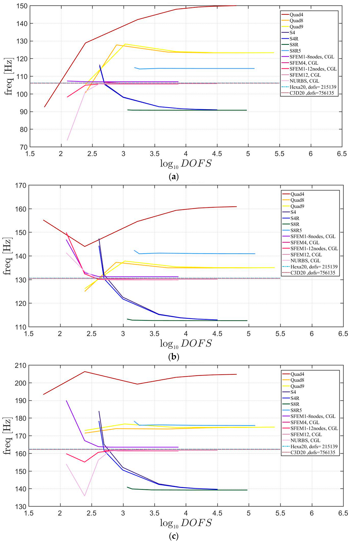
The free vibration problem will be carried out for isotropic skew plates of square shape with skew angle 30°. The skew angle is measured with respect to the vertical axis and the plate side is . The mechanical properties are .
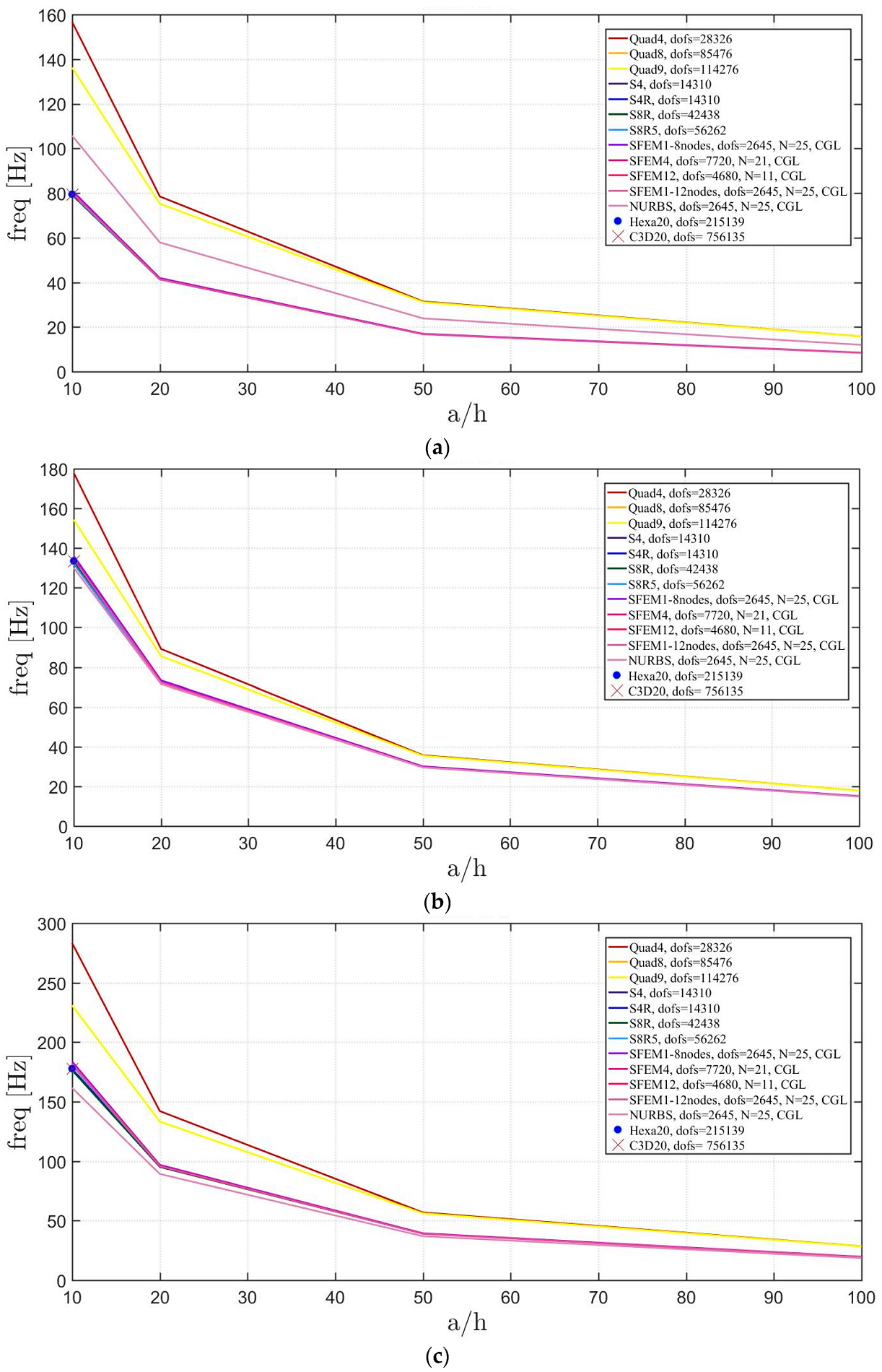
At first, convergence analysis is performed. In terms of SFEM the geometry is modeled with different structured meshes with 1, 2 (2 × 1), 4 (2 × 2), 8 (4 × 2) and 16 (4 × 4) elements, where the numbers in brackets report the edge divisions. Each element has been discretized with a variable number of grid points from 7 × 7 to a maximum number of 41 × 41 (for the single element only). For the sake of comparison, the FE models consider similar structured meshes with 5 × 5, 10 × 10, 20 × 20, 40 × 40, 80 × 80, and 160 × 160 elements. The first three mode shapes are depicted in Figure 3 where it is immediately clear that SFEM needs a lower computational effort to reach a stable solution. However, all the implemented elements agree with the same final result. It can also be noted that, the FE converges always “from above” due to its low order scheme, whereas the SFEM might converge from above and below. In the aforementioned convergence study, the thickness of the plate is thin because . Elements and for 8 and 16 SFEM elements. This selection is justified by the fact that the minimum computational effort is considered for each mesh. Instead of considering an analytical solution for the thick case () a three-dimensional FE model is implemented with brick elements with 20 nodes (Hexa20 for Straus7 and C3D20 for Abaqus). Thus, the 3D solutions are taken as a reference in the present comparison.
In the following study, the “thickness effect” is investigated for the same plate by considering a variable side-to-thickness ratio as (Figure 4). The reference mesh for the FE is a 40 × 40 and grid points for 1 and 2 SFEM elements, for 4 SFEM. By increasing the plate thickness, some models have a lower accuracy than their correspondent thin cases as Tri3 and Quad4, which overestimate the frequency. On the contrary, S8R5 underestimate the same frequency. The only expected error at this stage is given by the S8R5 because such element is indicated as “thin” in the Abaqus software, whereas no information is given on the Straus7 elements.
4.1.2. Circular Plates
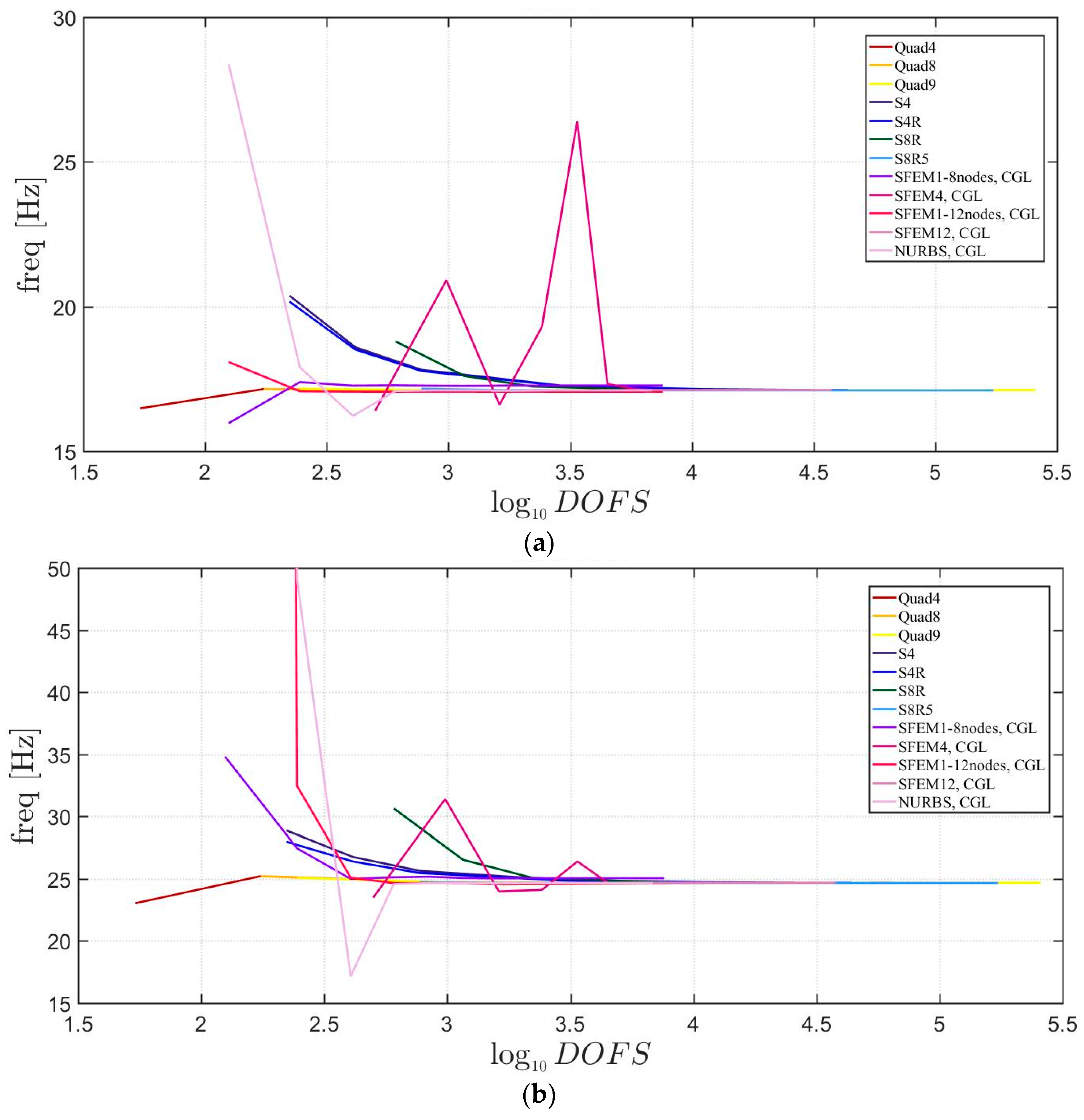
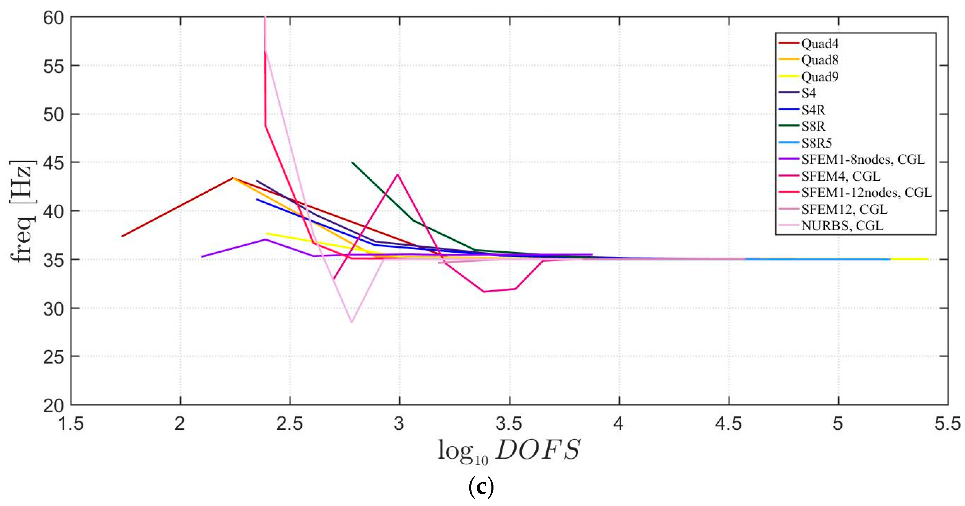
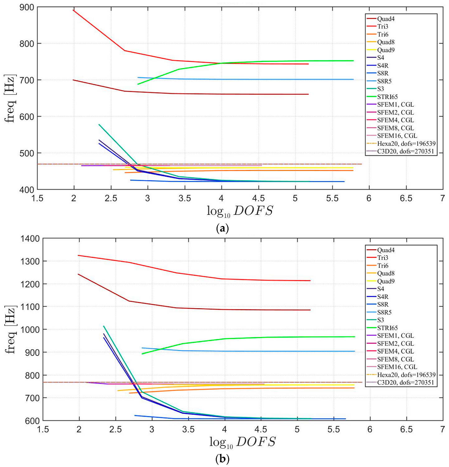
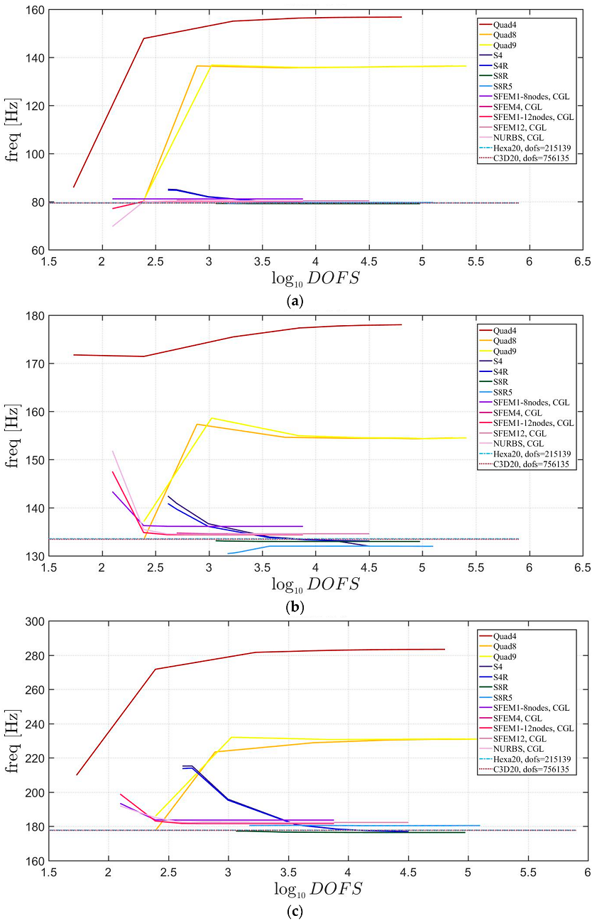
In the present section, the free vibrations of isotropic circular plates with fixed external edges are considered. The material properties are the same as the ones taken in the previous section as with a unitary plate radius of . The plate can be considered as “thin” because . Convergence plots of the first three mode shapes are depicted in Figure 5.
Unlike classical FE, the SFEM can use also a single element to describe a circular plate. In fact, a single element mesh mapped with a Lagrangian, eight nodes and 12 nodes element are utilized. Moreover, a single element is considered using NURBS. These single-domain meshes are studied with different grid points from 7 × 7 to a maximum number of 41 × 41. In addition, the plate has been divided into four (one element per quarter) and 12 elements (three elements per quarter) with eight nodes using Lagrangian mapping. As far as the Straus7 meshes are concerned, the starting mesh is made of 12 elements with eight nodes (three elements for each quarter). The other discretizations are obtained by dividing each finite element regularly with the following equal number of divisions 2 × 2, 5 × 5, 10 × 10, 15 × 15, 20 × 20, 30 × 30. The mesh in Abaqus are generated by setting the number of elements on the plate radius and one-quarter of the circumference, respectively. Therefore, the following discretizations have been considered: (5, 1), (10, 5), (20, 15), (30, 25), (40, 35), (50, 45), (60, 55). It is remarked that the present models consider the double symmetry of the structure by meshing all plate four quarters in the same way. This approach improves the stability of the solution.
It is observed in Figure 5 that all of the elements converge to the same solution except for the SFEM, which made a single element with eight nodes. This error is due to a wrong geometry approximation, because eight nodes are not sufficient to approximate a circular geometry. Only a parabolic shape can be modeled exactly. On the contrary, the NURBS approximation using SFEM increase its geometrical approximation by increasing the number of grid points inside the element.
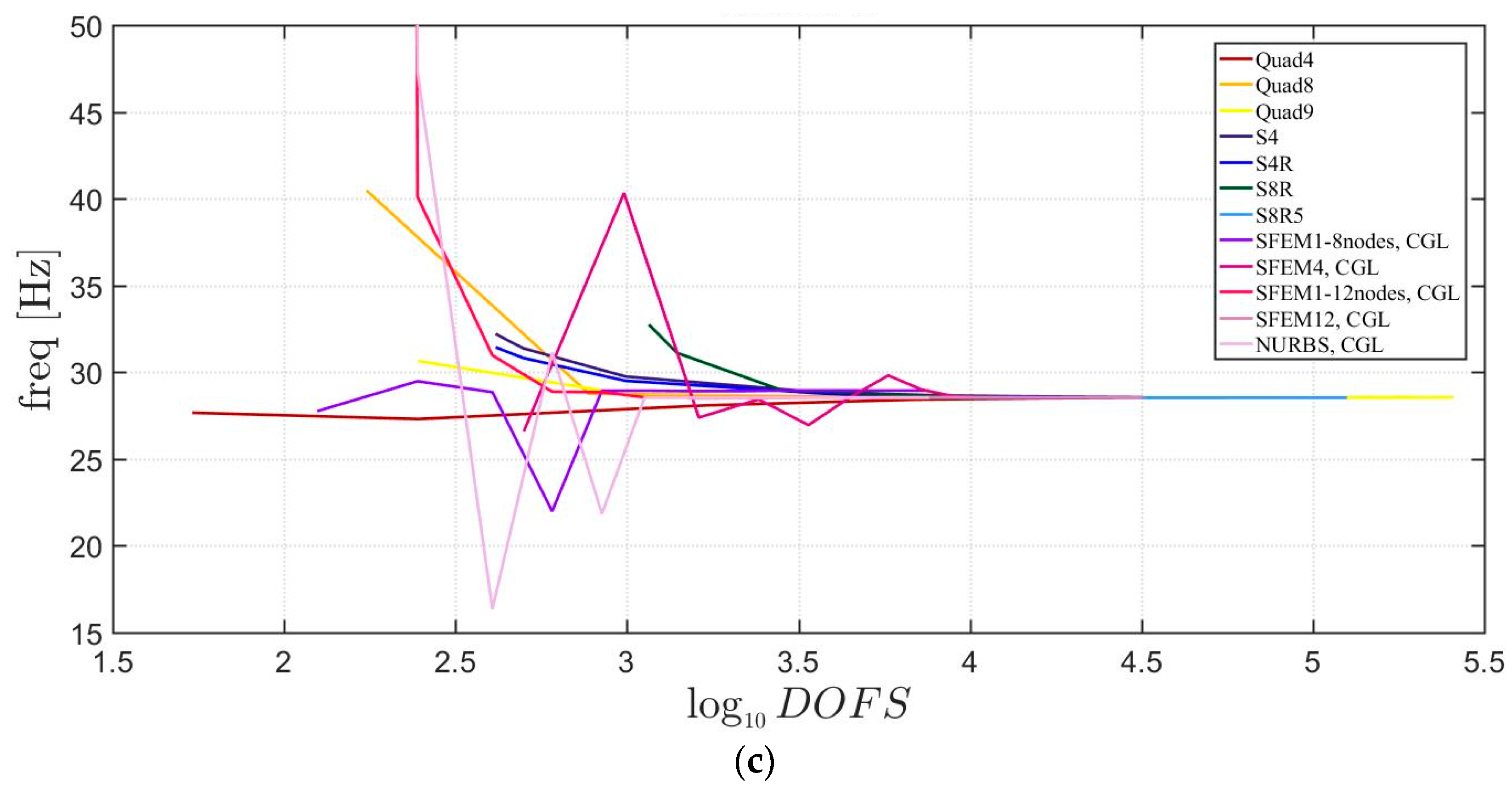
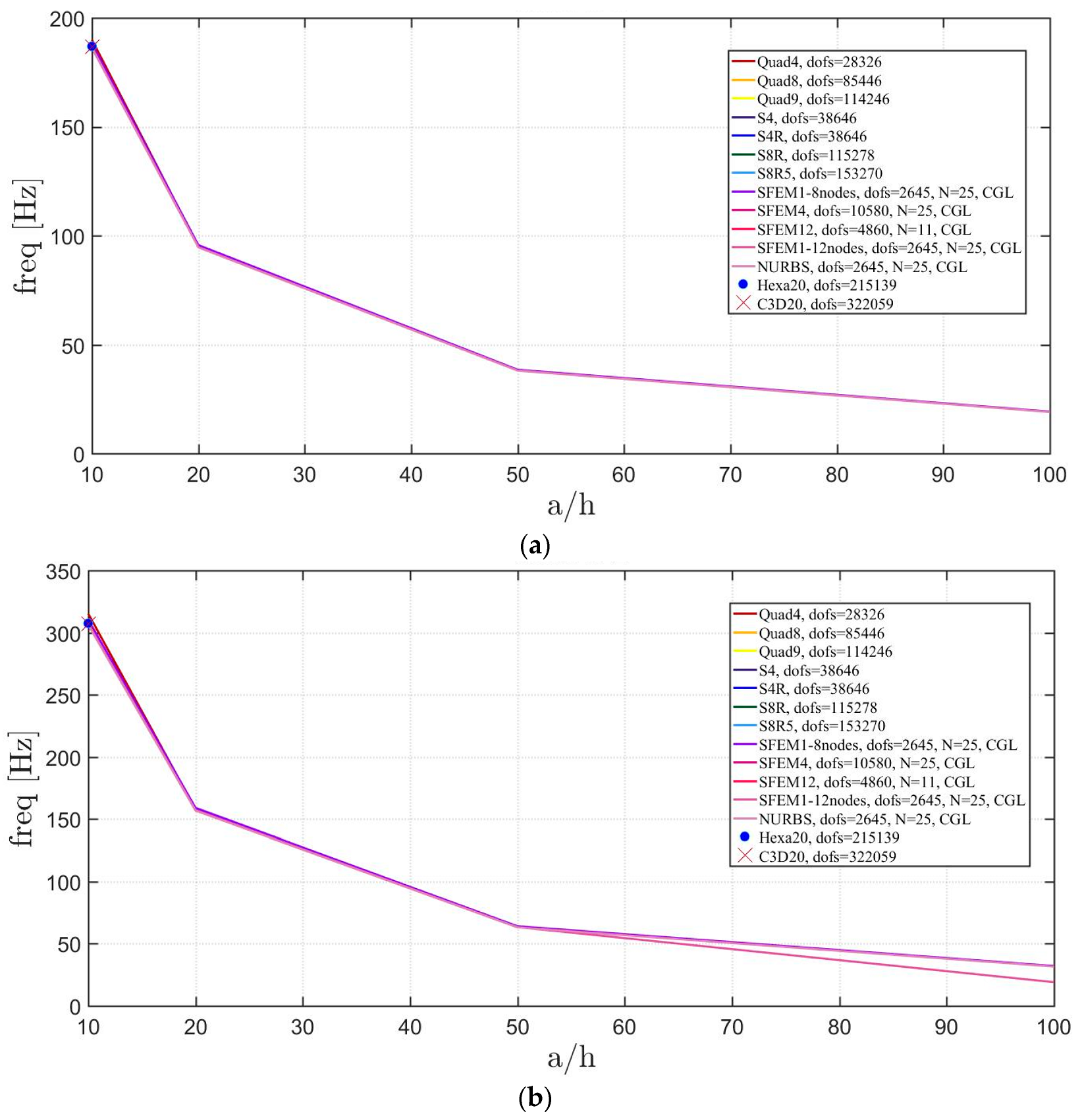
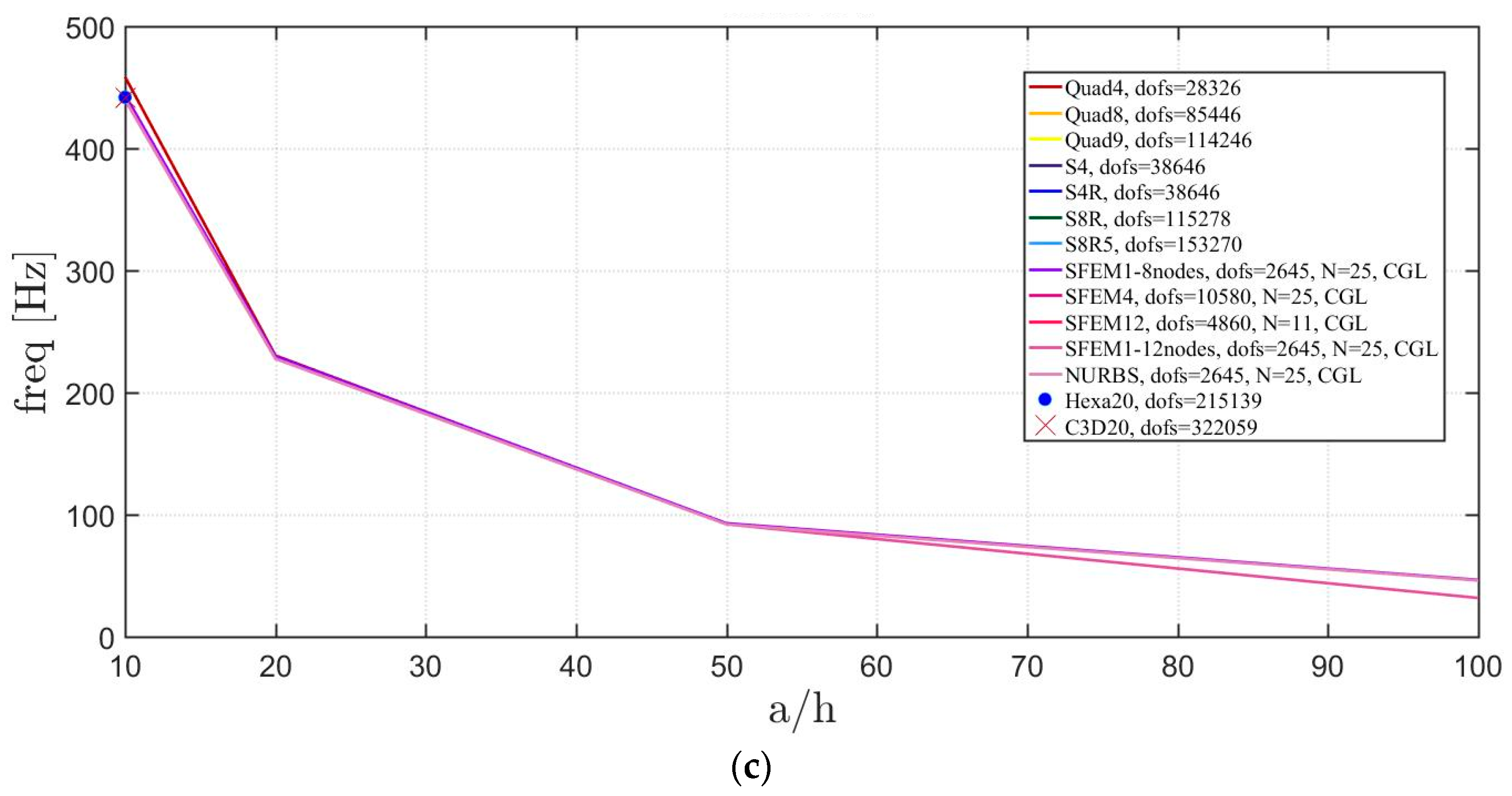
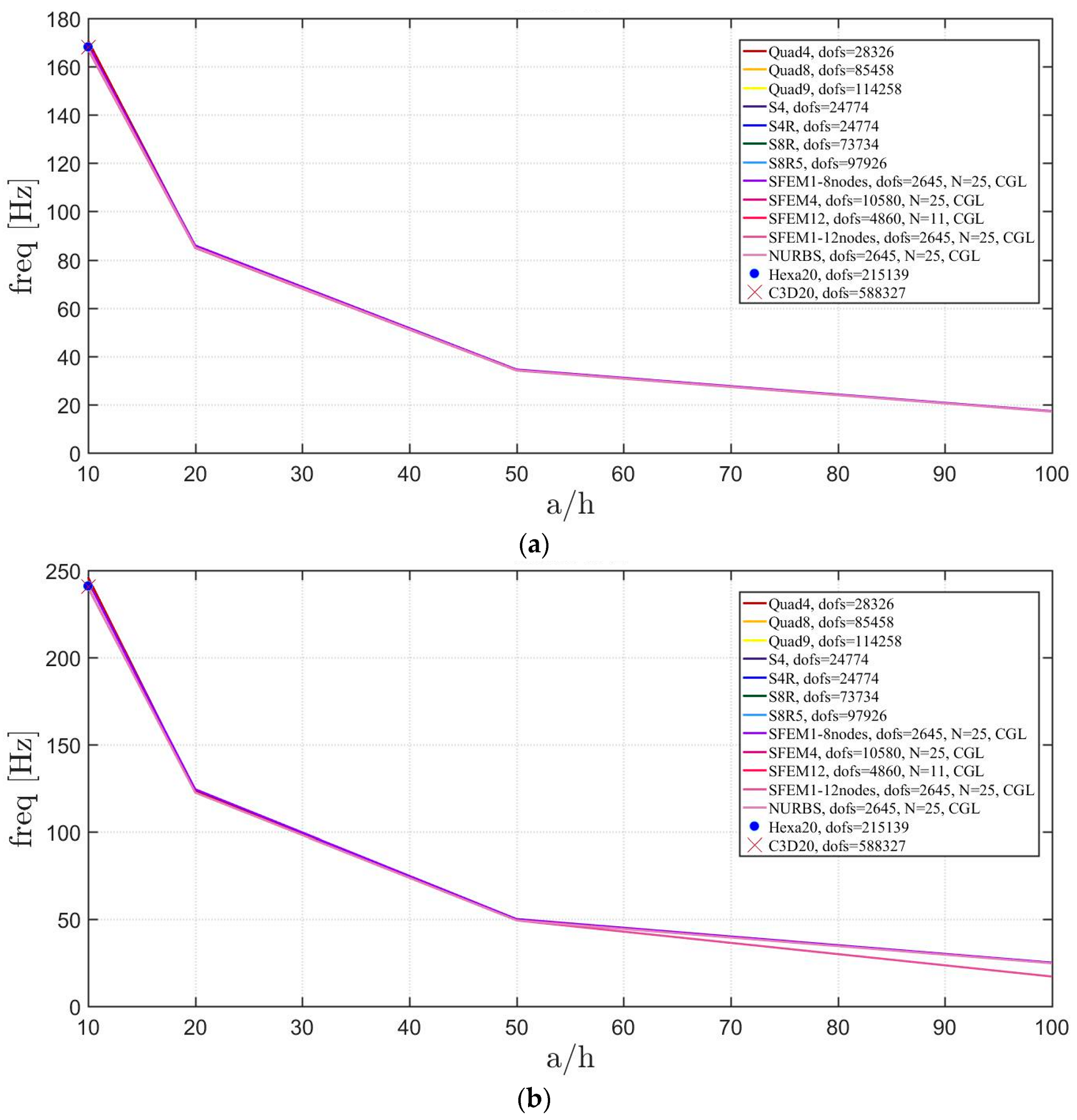
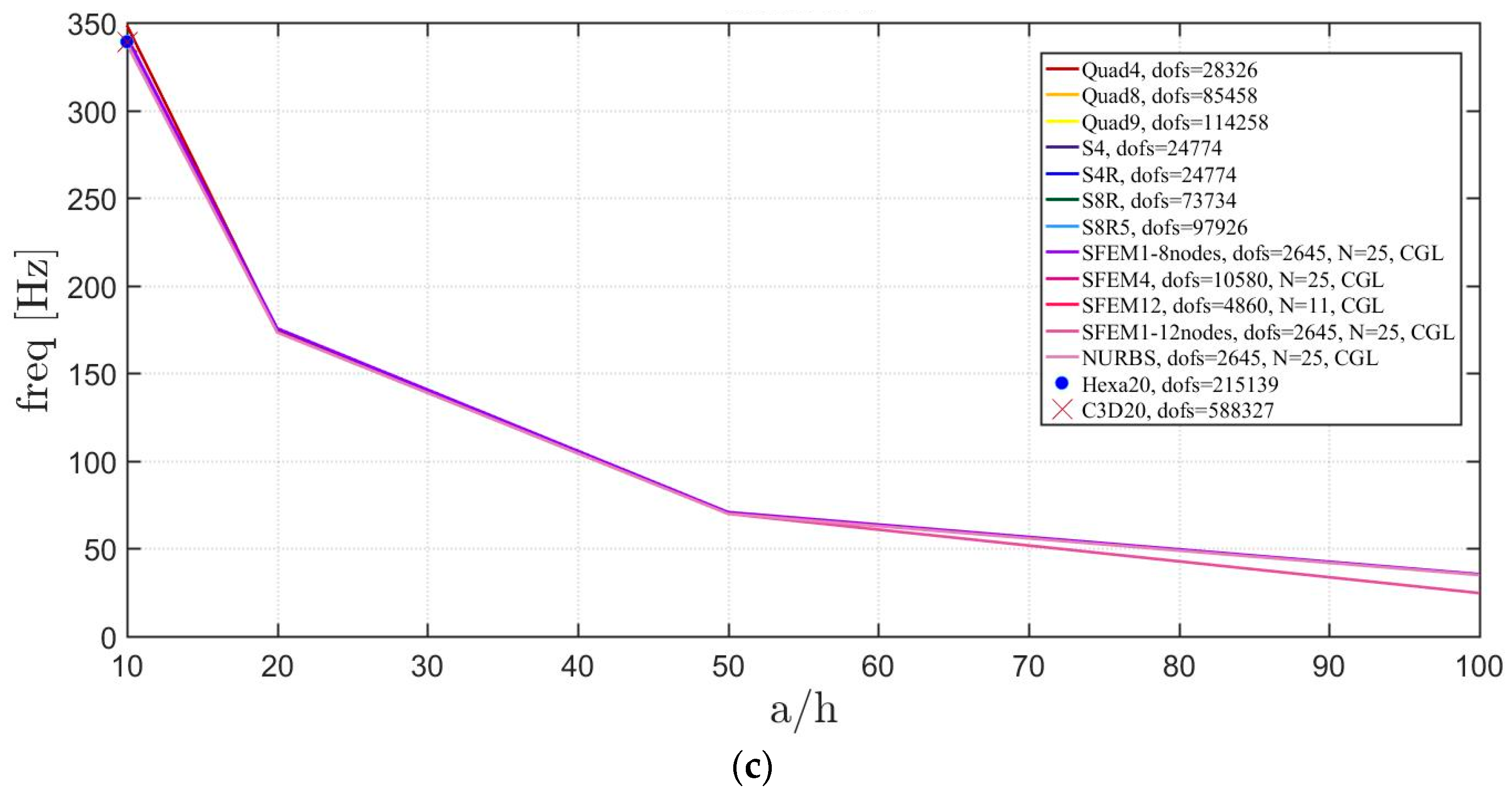
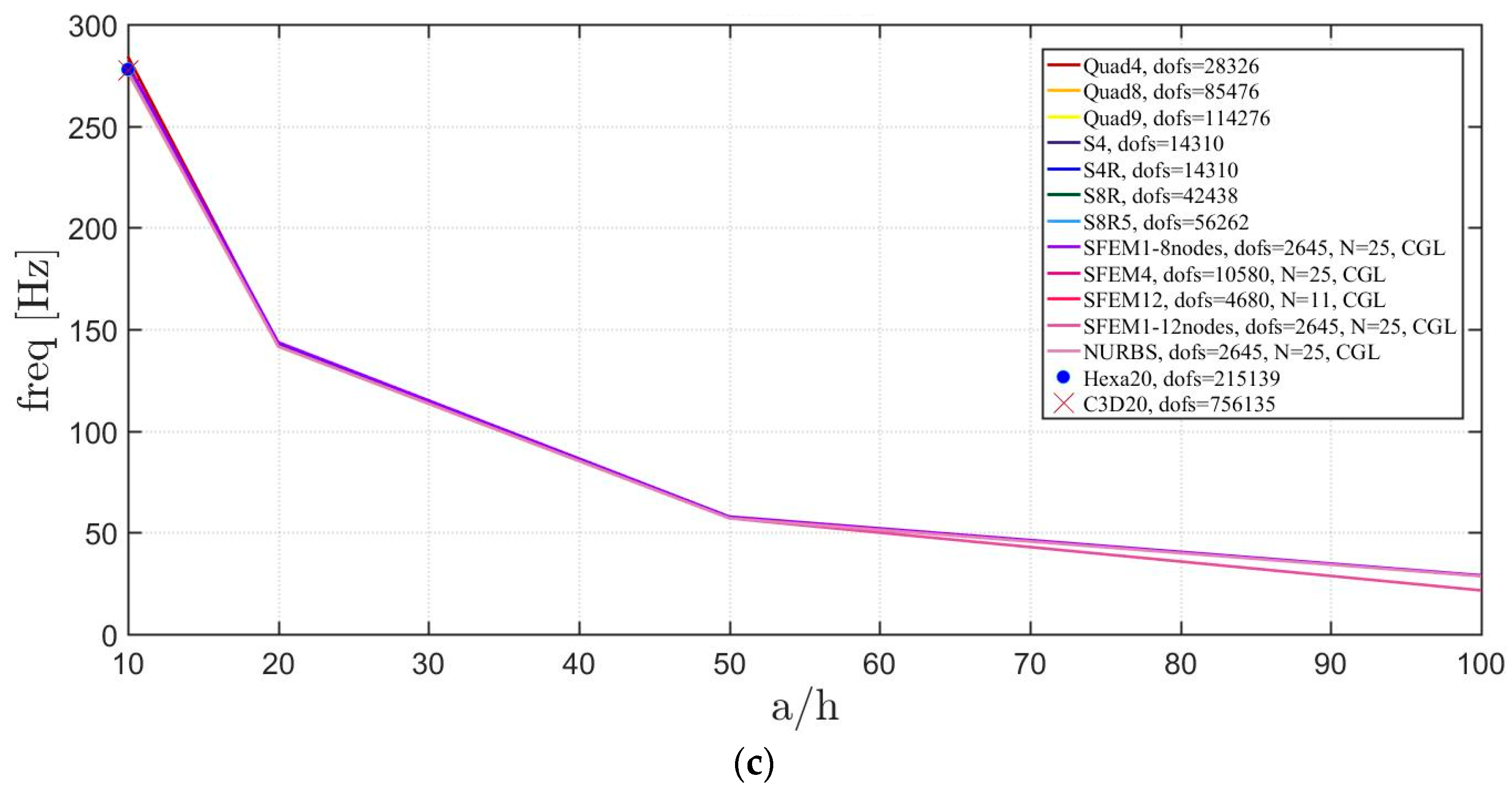
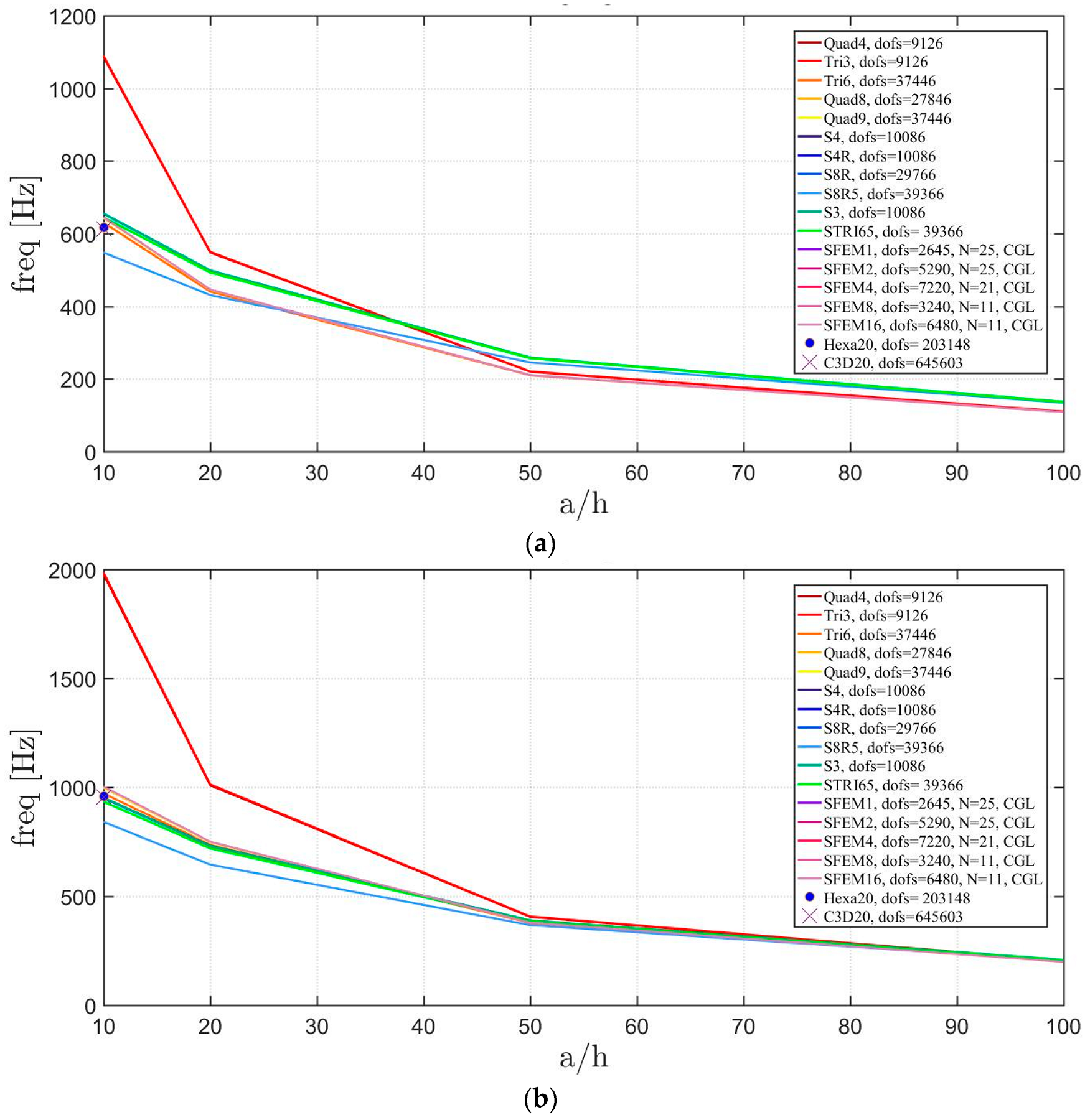
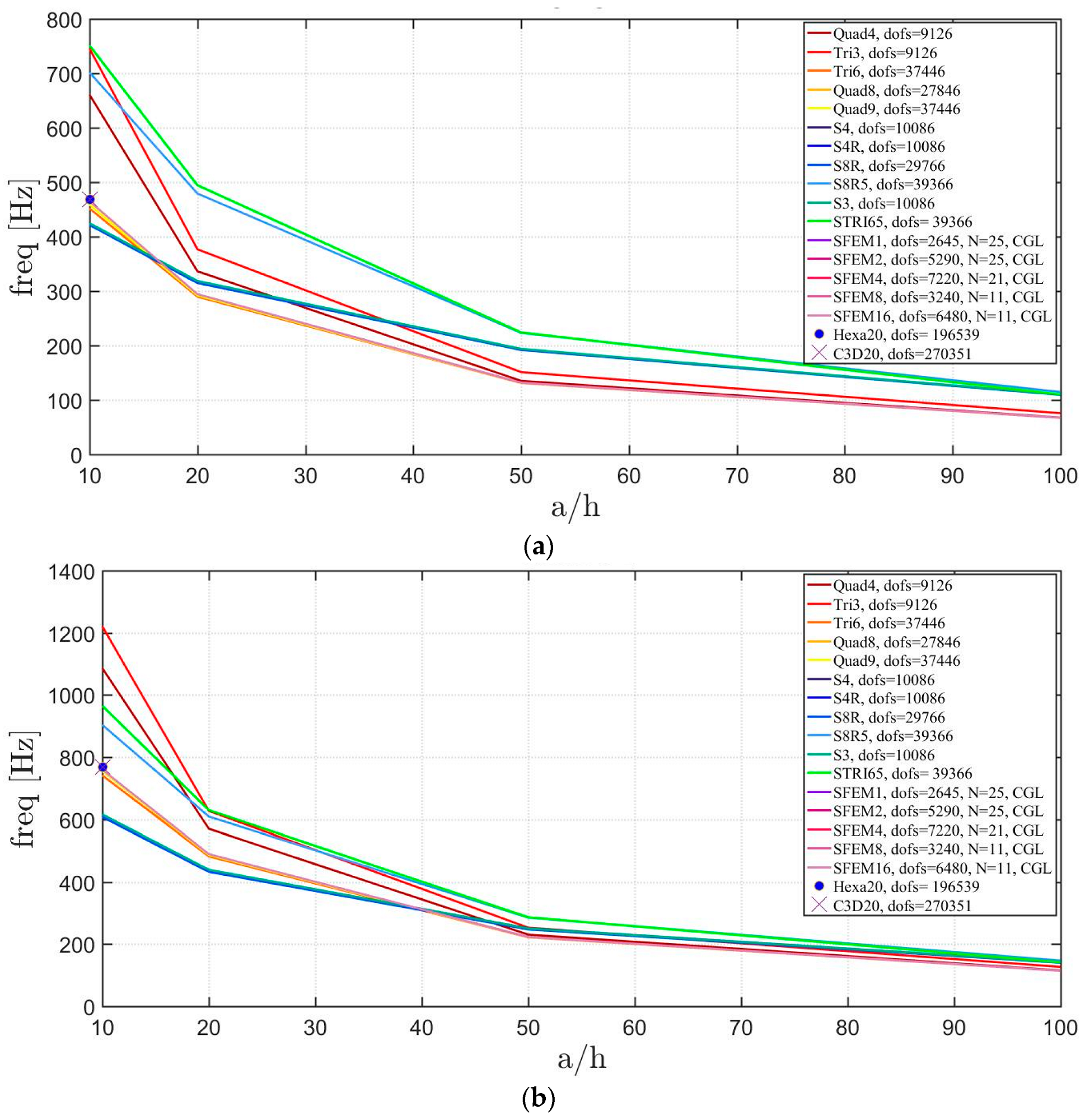
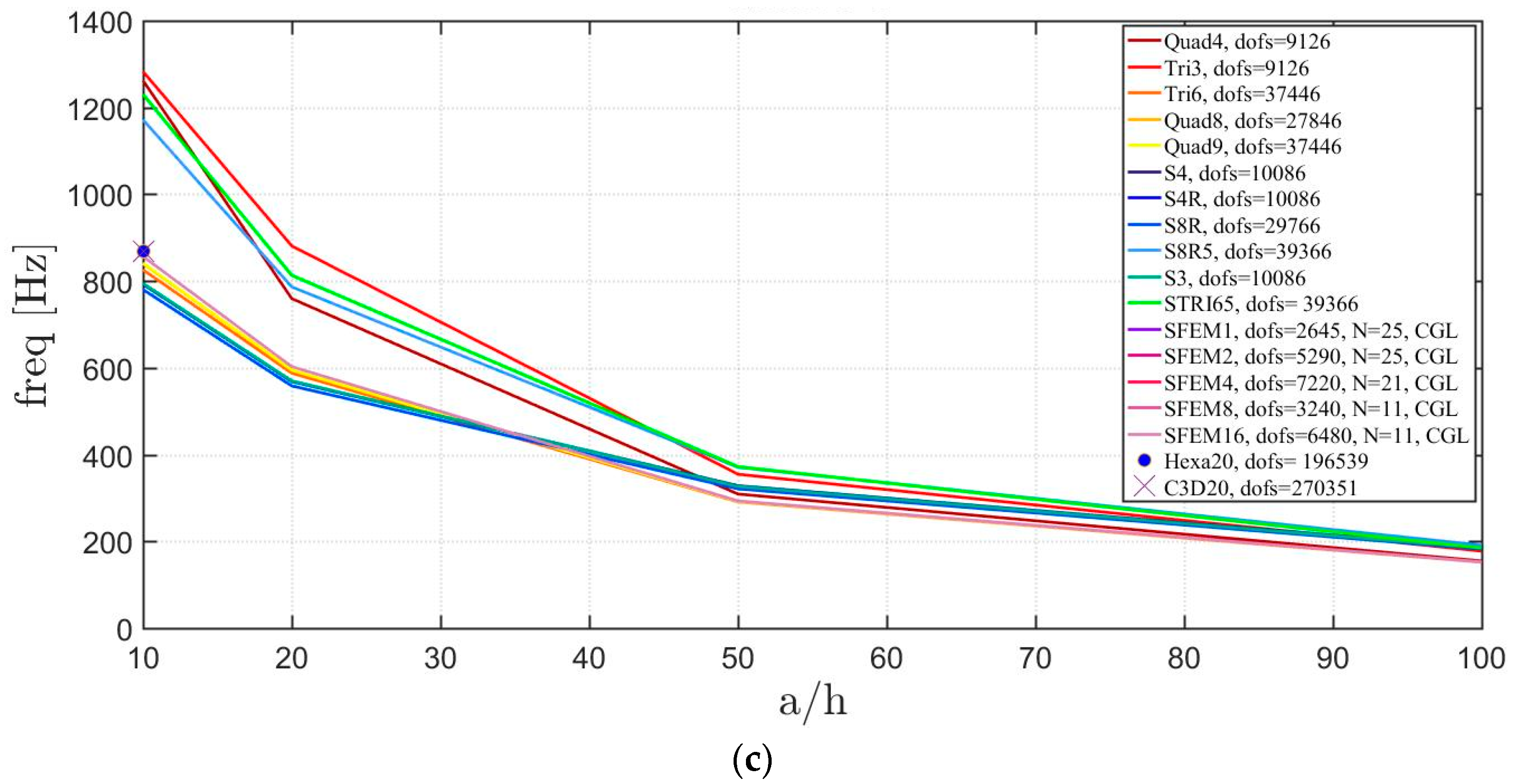
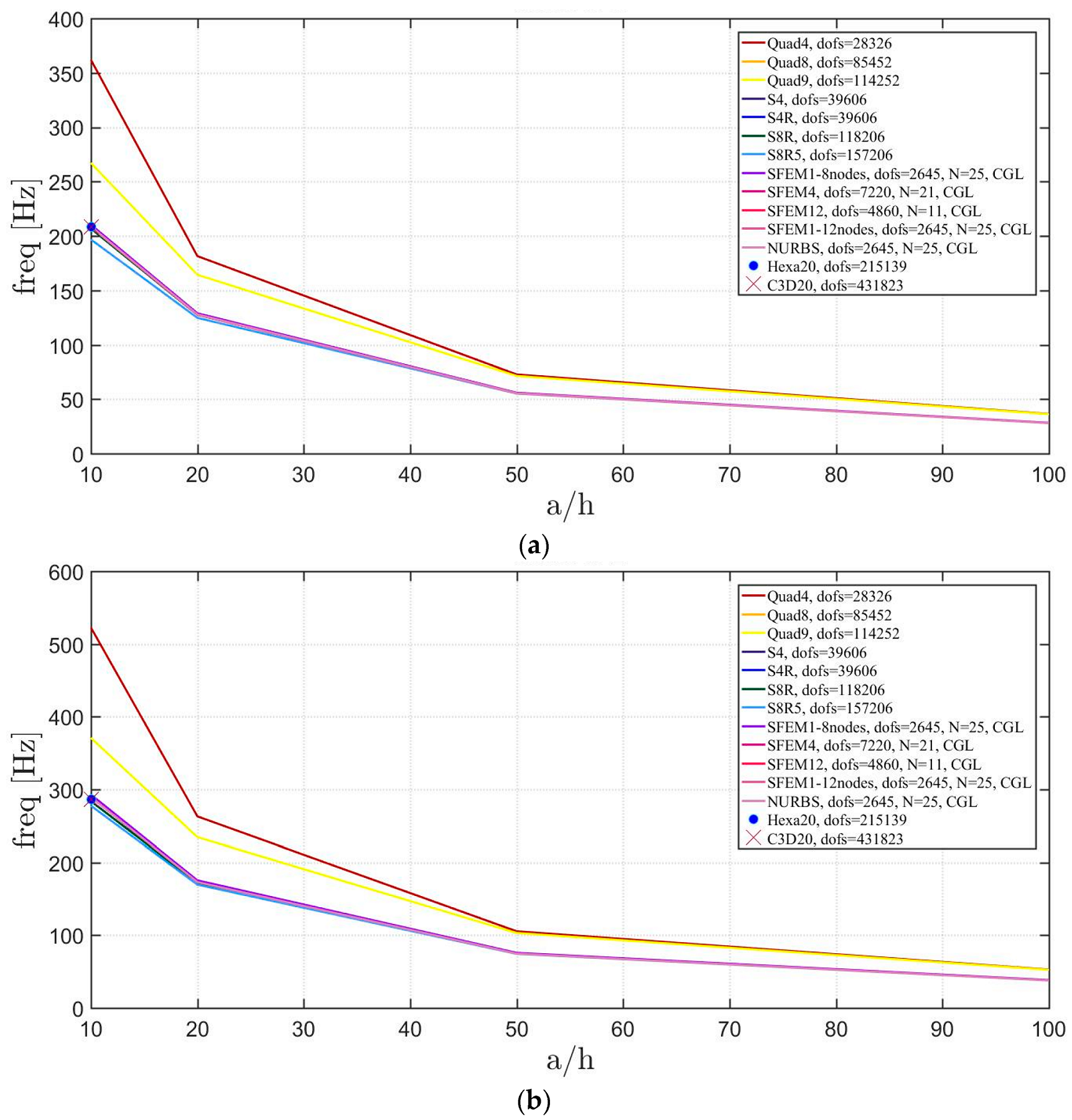
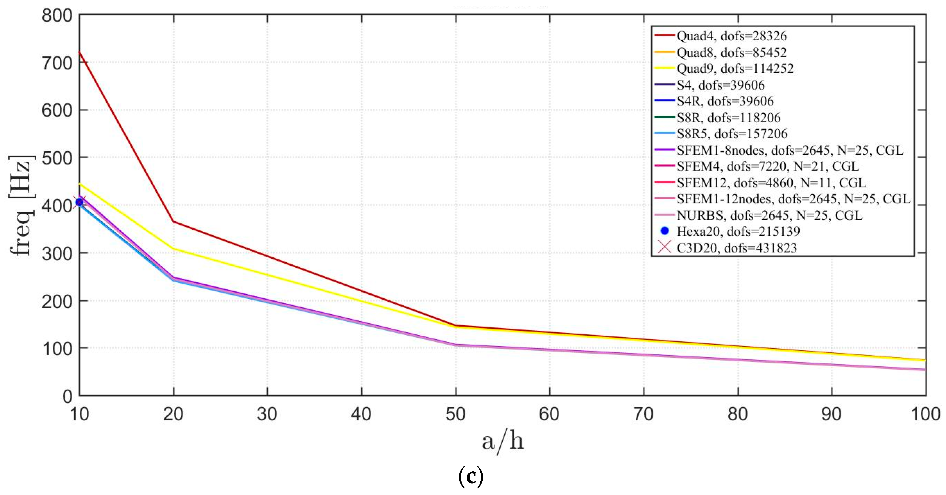
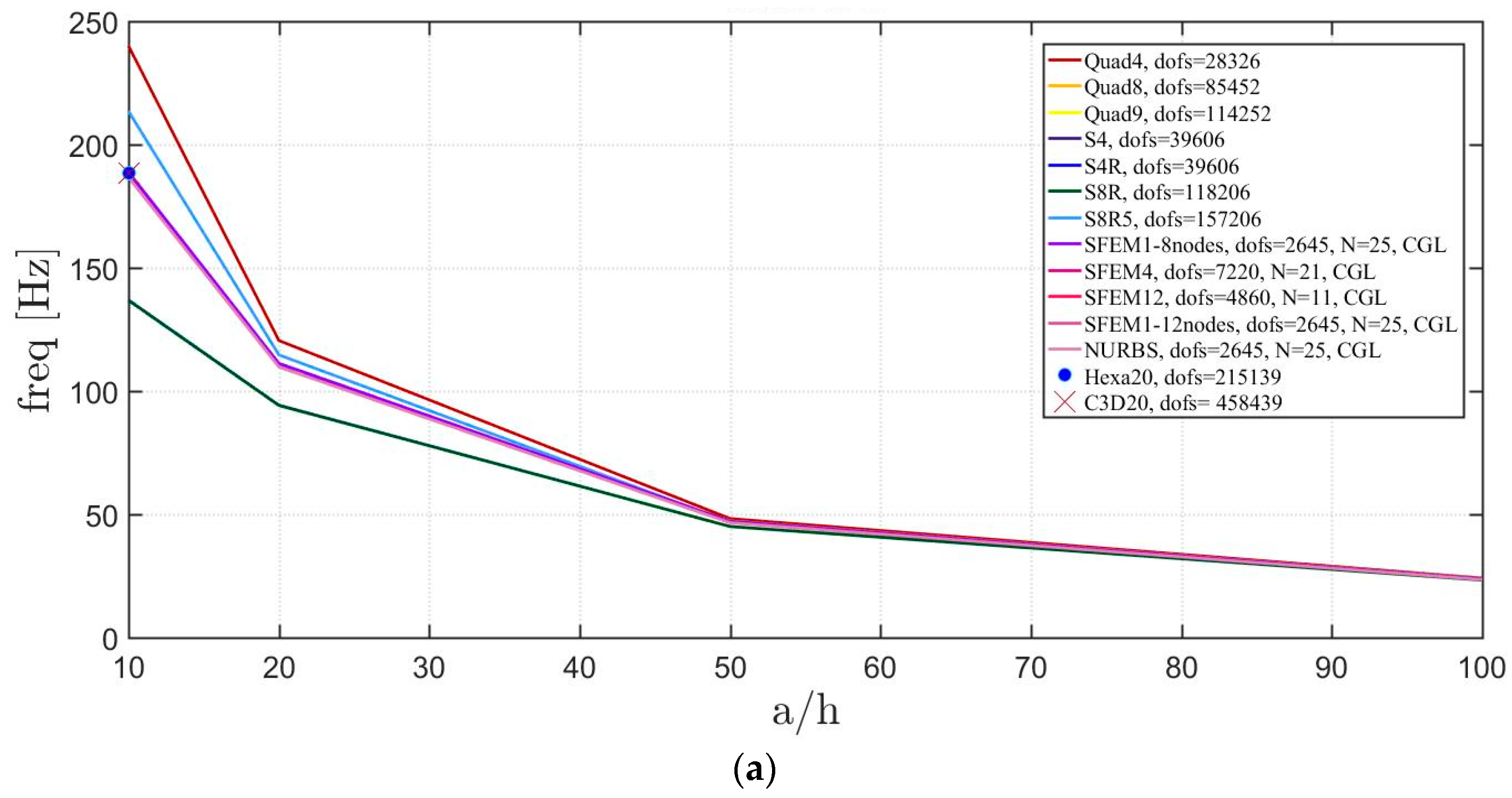
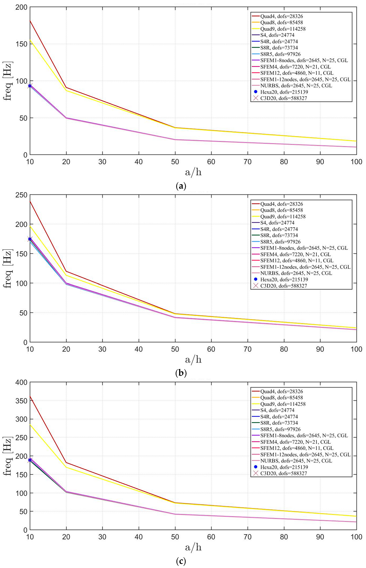
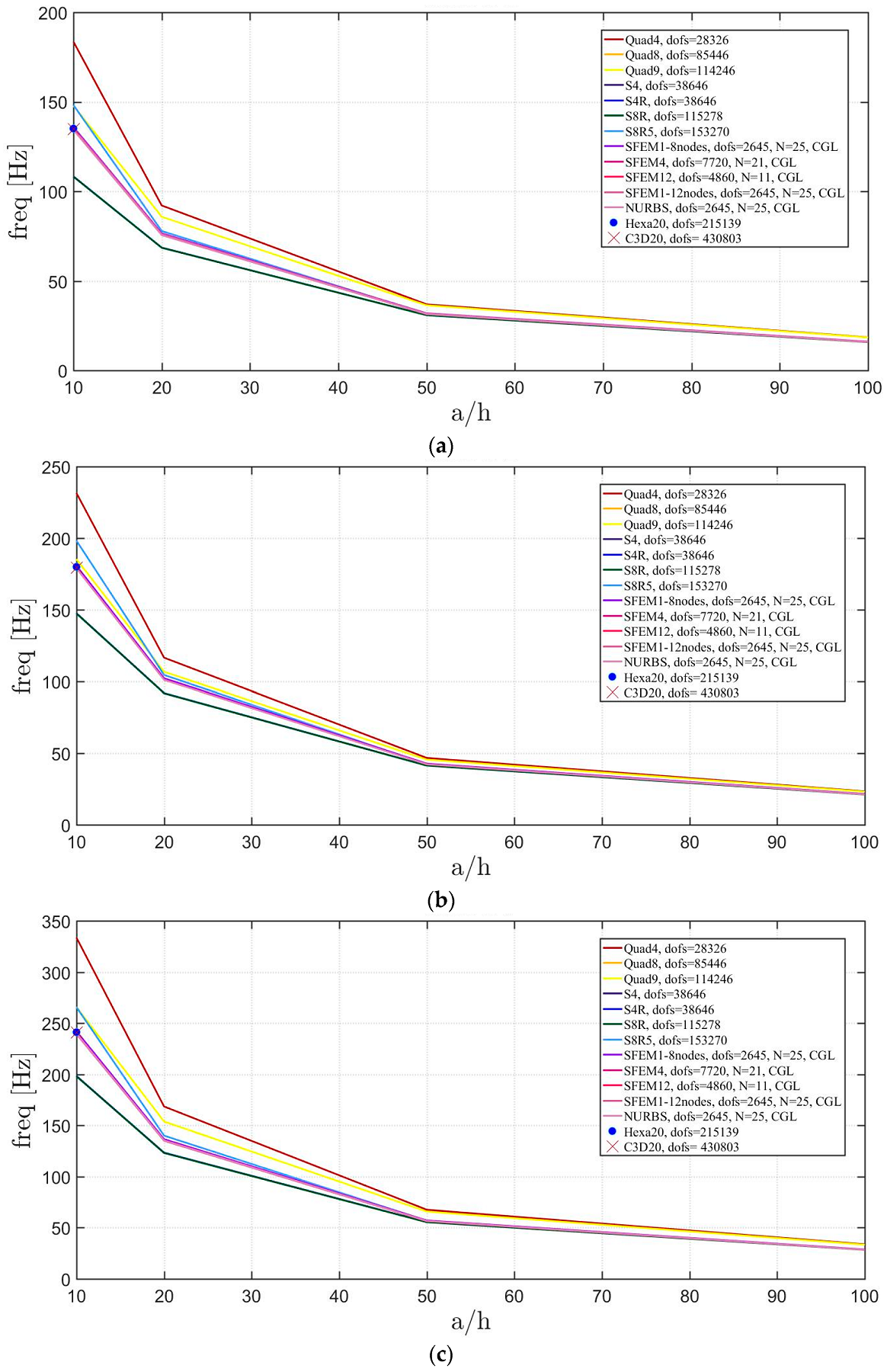
In the following, the effect of the plate thickness is shown by considering . With reference to the discretizations defined above for Straus7, the reference mesh is the one with 20 × 20 (for a global number 4800 elements) and (50, 45) is the number of elements used in Abaqus for each circular quarter. Finally, the SFEM considers 25 × 25 grid points for each of the previous meshes, except for the mesh with 12 elements that considers a 11 × 11 grid.
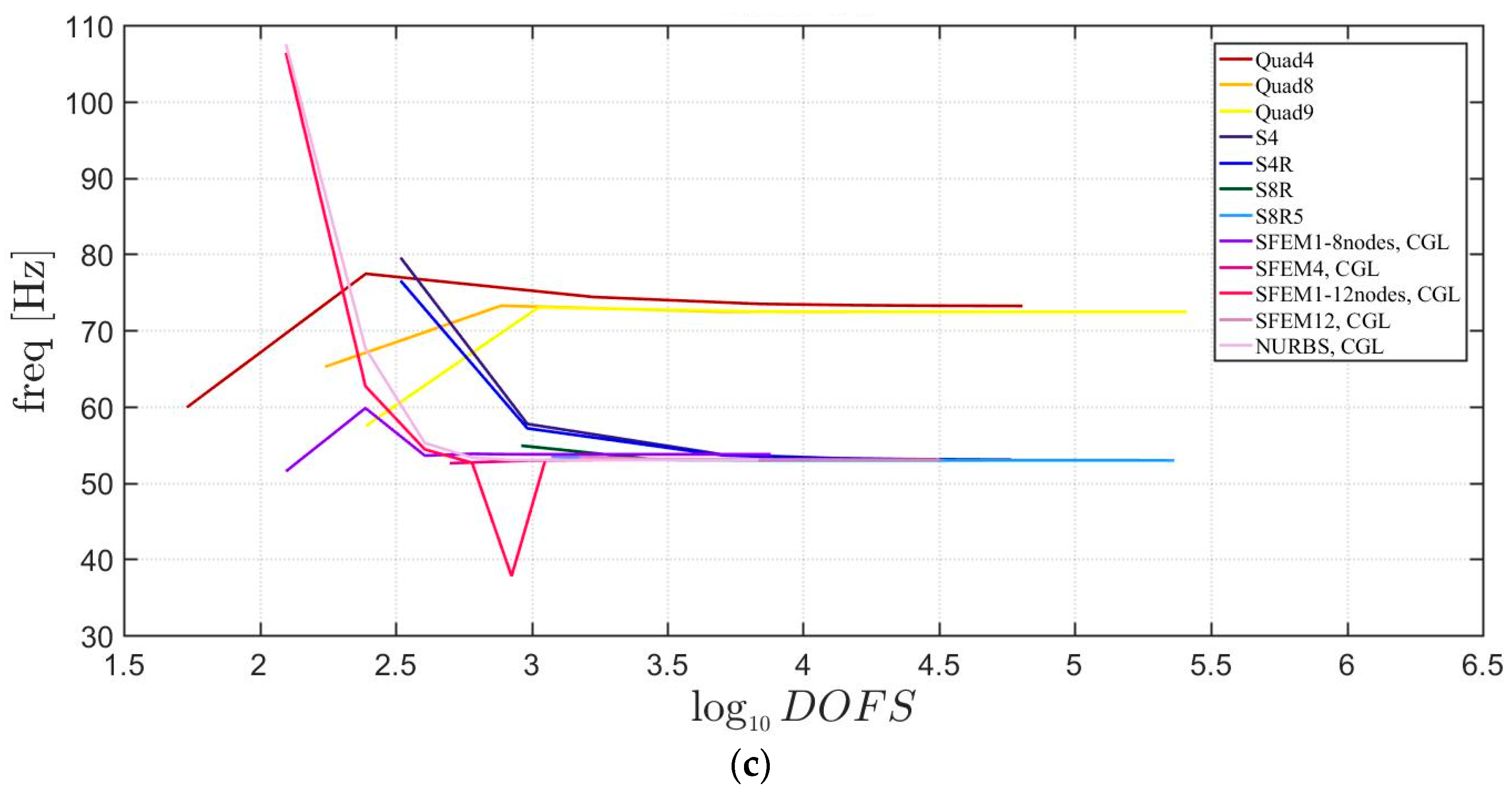
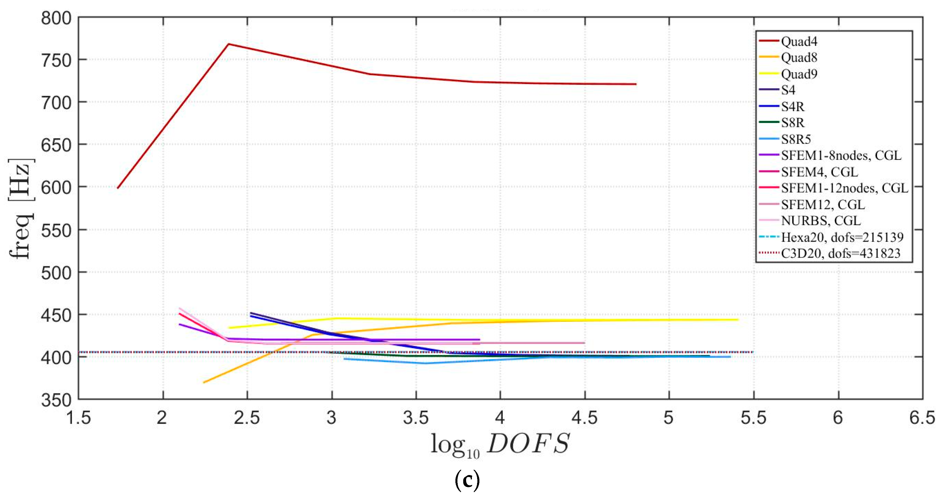
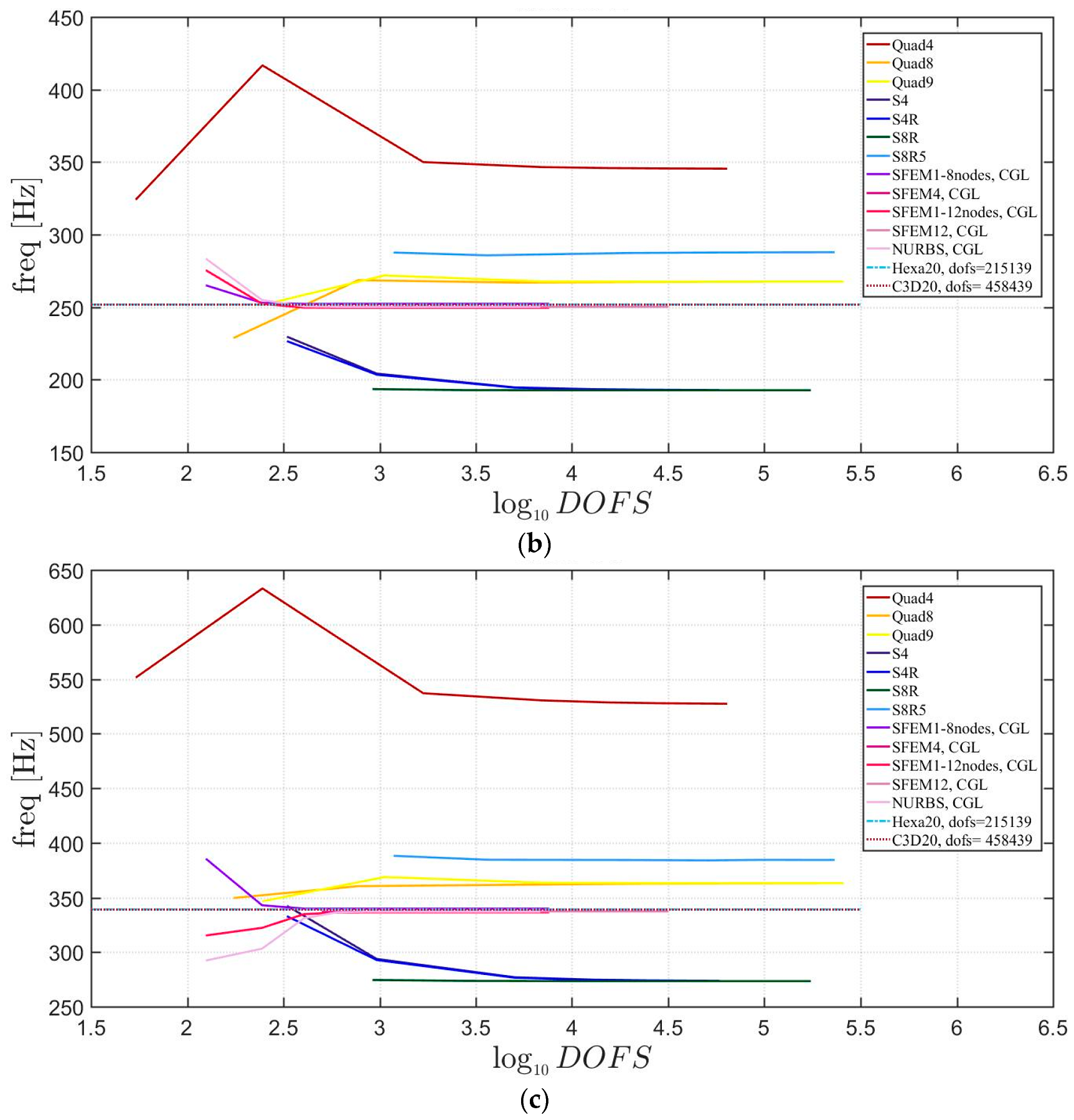
Only for the thick plate case , 3D FE models are prepared using Hexa20 (in Straus7) and C3D20 (in Abaqus) that are considered as reference solutions. It can be noted that, all the first three frequencies agree with a negligible difference for thick plates due to the influence of the shear effect. The total number of degrees of freedom (DOFS) considered can be seen from the legends in Figure 6.
4.1.3. Elliptic Plates
In the present section, isotropic elliptic plates of different shape are investigated. These structures are characterized by the two semi-axes (minor) and (major). The plate properties are so thin plates are studied (). The following simulations consider different values of the semi-axes ratios and the external edges all clamped.
The SFEM meshes follow the same scheme as the previous case of circular plates. Therefore a single element mesh with eight and 12 nodes is considered, a mesh with four and 12 elements with eight nodes and finally a single element with NURBS. The grid distribution inside each element considers a different number of points from 7 × 7 to 41 × 41 (only for the single element cases). The Straus7 meshes consider a mesh of 12 elements as a starting geometry (with three elements for each quarter) and the following discretizations occur for each element: 2 × 2 (48 elements), 5 × 5 (300 elements), 10 × 10 (1200 elements), 15 × 15 (2700 elements), 20 × 20 (4800 elements), 30 × 30 (10800 elements). Abaqus meshes are adapted according to the geometry under consideration. In particular, the number of elements per side is selected to reduce mesh distortions. The following triplets indicate the number of elements along and the third digit stands for the number of elements on the external edge (correspondent to one-quarter of the plate). Thus, has (2,3,5), (4,6,8), (8,12,14), (16,24,24), (32,48,50), (36,52,54), (40,56,58). has (1,2,4), (2,4,6), (4,8,8), (8,16,16), (16,32,32), (24,48,48), (32,64,64). has (1,3,6), (2,5,7), (4,10,10), (8,20,20), (12,30,30), (16,40,40), (24,60,60). It is obvious that the present meshes take into account the plate double symmetry.
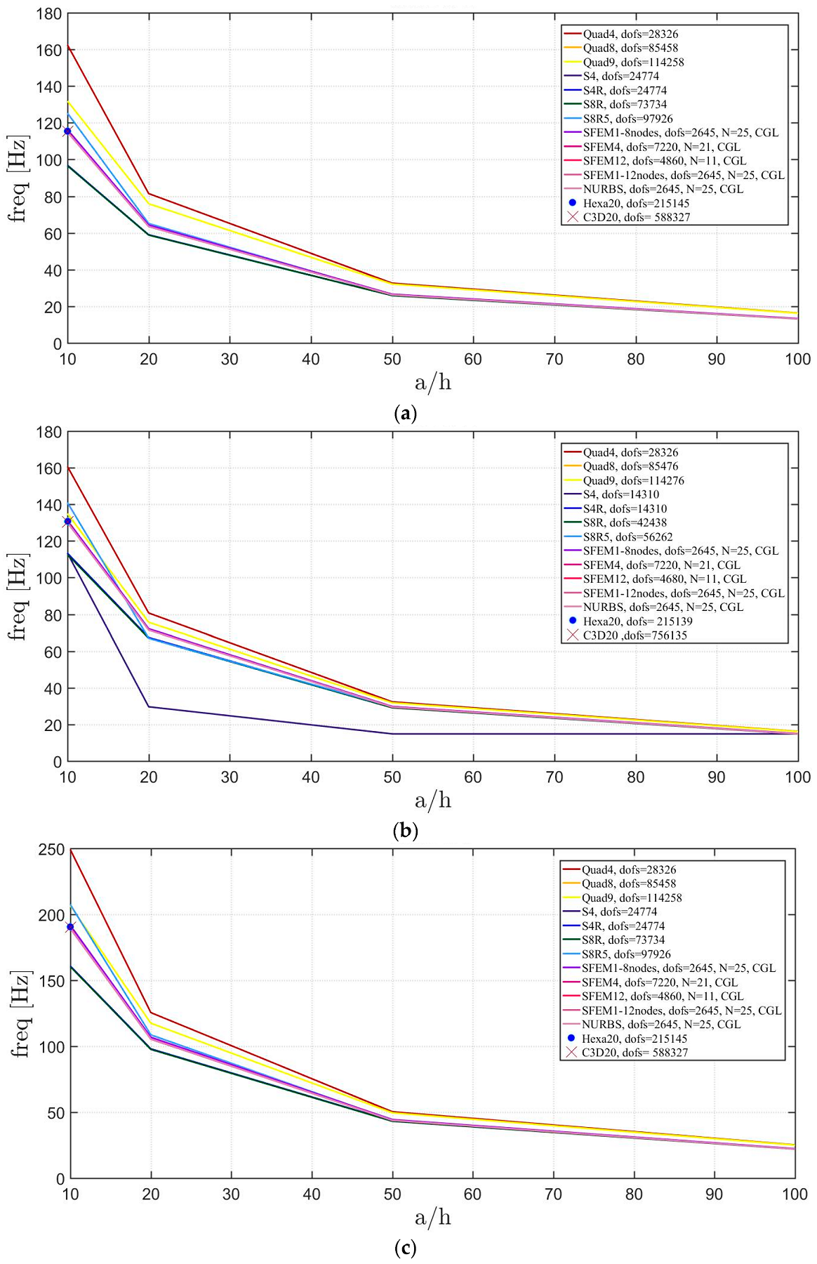
Figure 7, Figure 8 and Figure 9 include the convergence behavior of the first three mode shapes for three different isotropic elliptic plates with , respectively. It can be generally observed that, all the solutions agree well except for the single SFEM element with eight nodes due to the same geometric error that was present in the circular plate case.
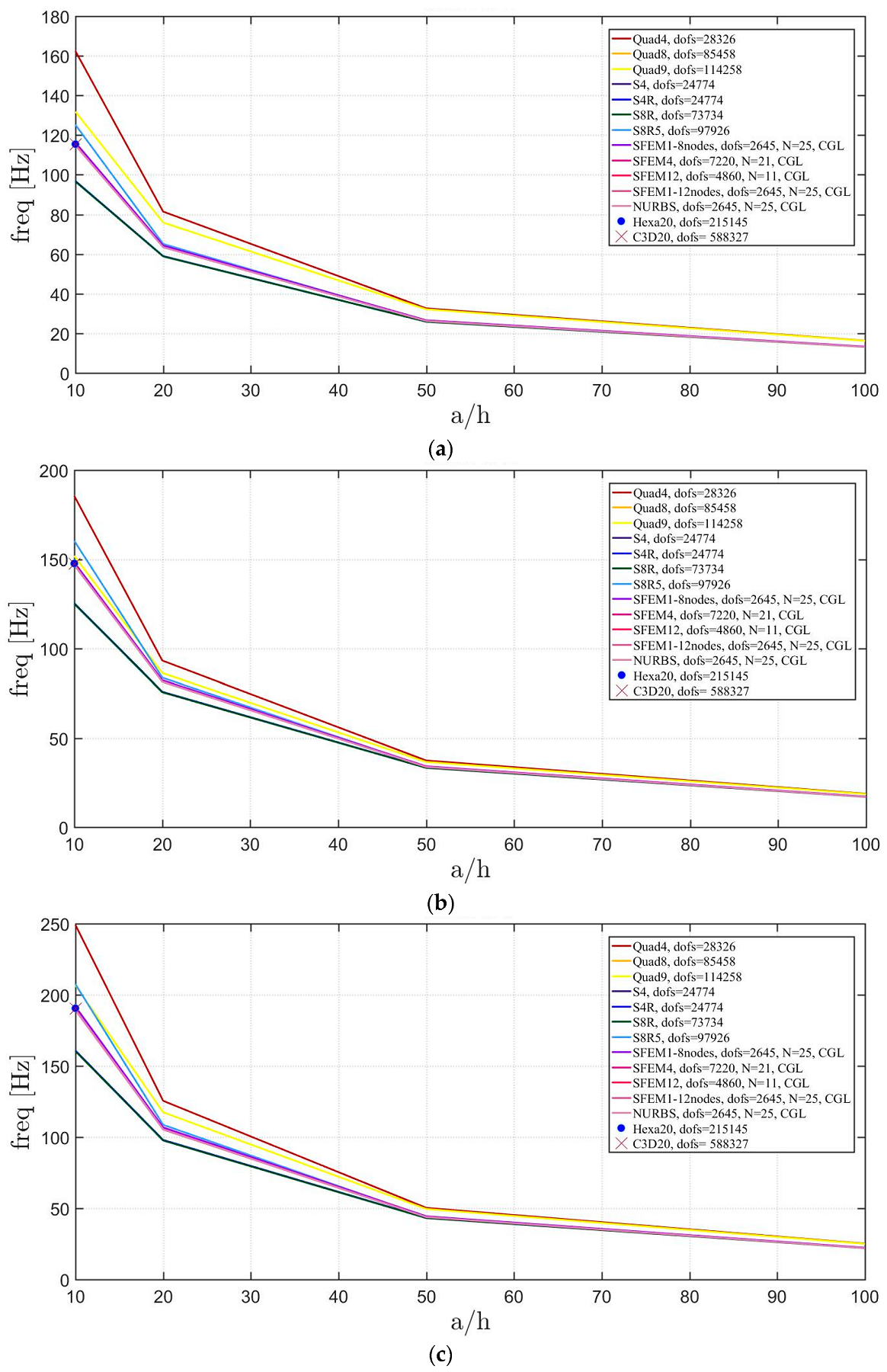
The effect of the thickness is considered in the following for the same elliptic plate geometries investigated above. For the following examples, the grid points for the GDQ meshes are 25 × 25, except for the mesh made of 12 elements that considers a 11 × 11 grid.
The Straus7 mesh considers 20 × 20 decomposition of the starting 12 elements mesh for a total of 4800 elements and three different meshes are considered according to the shape for Abaqus: (36,52,54), (24,48,48), (16,40,40) with the same meaning of the symbols discussed above. References models are made using 3D FE bricks for by using Hexa20 in Straus7 and C3D20 in Abaqus. The total number of DOFS used is indicated in Figure 10, Figure 11 and Figure 12. All the solutions agree, apart from the Quad4 meshes that have a small deviation for thick plates.
4.2. Laminated Composite Materials
In the present section, the free vibration problem of laminated composite plates is discussed. The structures of the present study follow the same scheme of the previous section. Therefore, skew plates, circular plates and elliptic plates are shown. The reference material is an orthotropic monoclinic ply with mechanical properties: , , , , and . In the following computations, two lamination schemes are considered. The first symmetric (for skew plates), for circular and elliptic plates and the second one generic for skew, circular and elliptic plates. The former selection has negligible coupling matrix, whereas the latter has all the coefficient of the stiffness matrix not null. The plates are completely clamped on all the external edges in all the following cases. The same finite elements and domain decomposition approaches of the previous section are considered, therefore, no further detail will be reported in this regard. Comments will be given only on the results provided by the composite plate configurations.
4.2.1. Skew Plates with Skew Angle of 30°
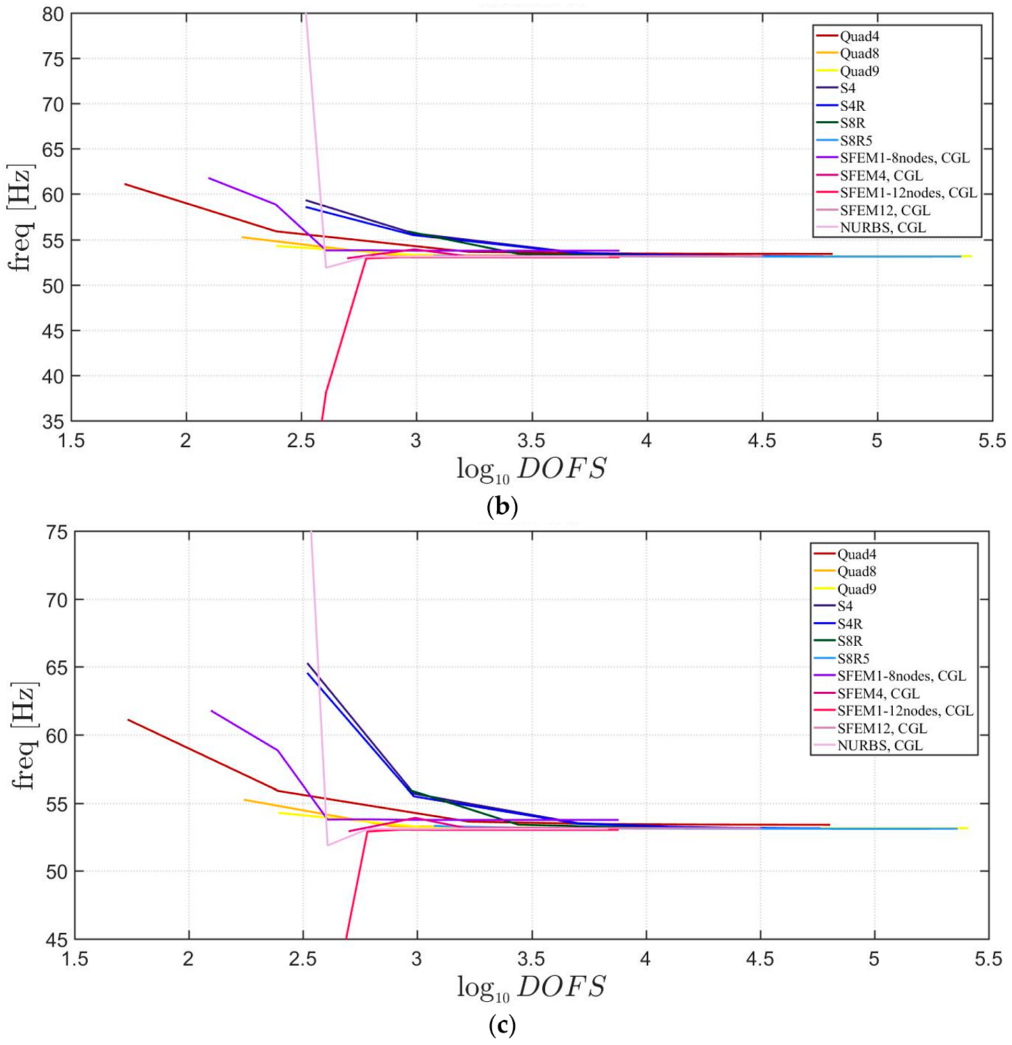
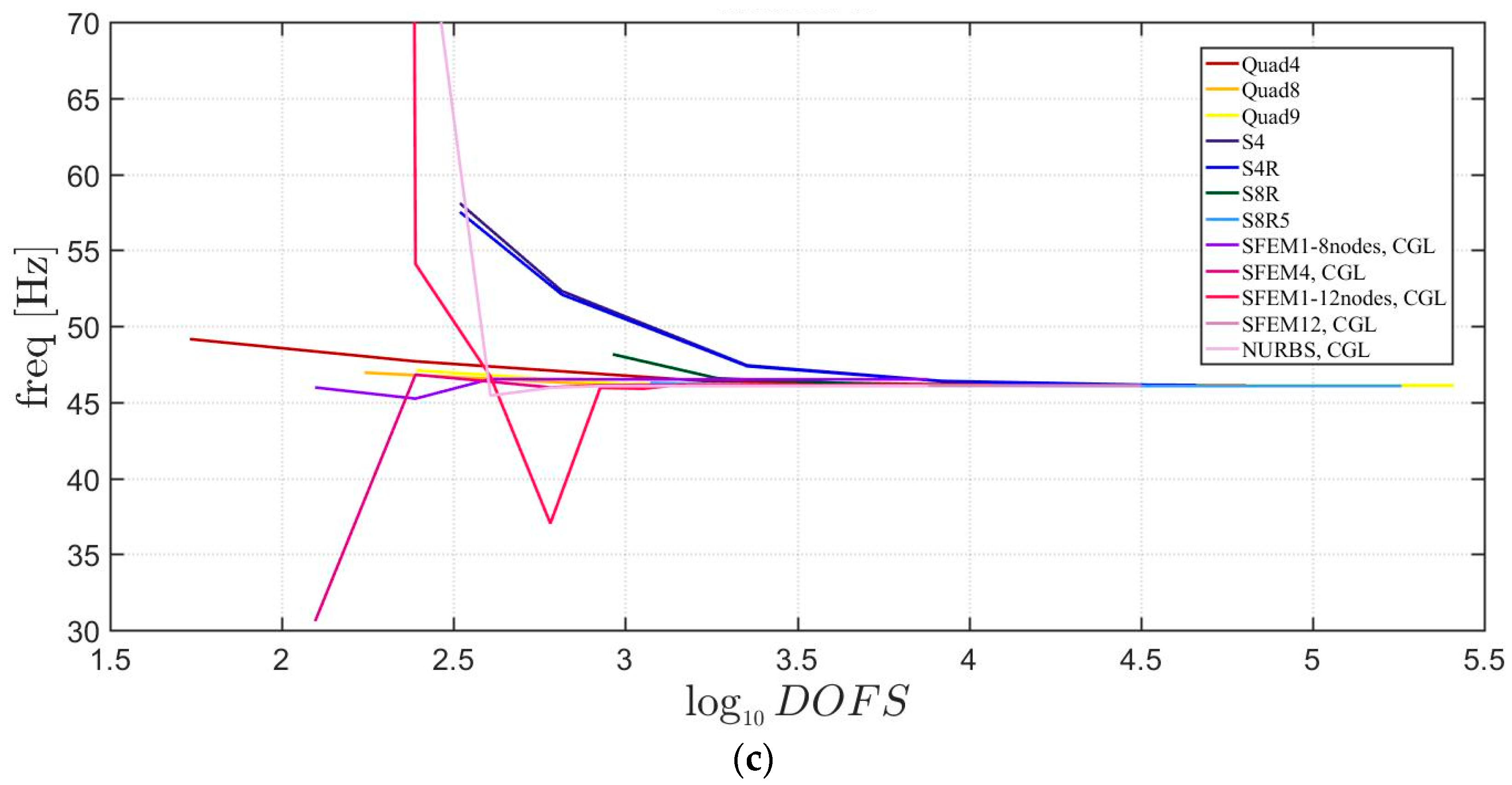
Convergence simulations are carried out for a thickness-to-width ratio of . 3D FE models are used as a reference with fine meshes (Hexa20 for Straus7 and C3D20 for Abaqus). Figure 13 reports the first three mode shapes for the symmetric lamination scheme, whereas Figure 14 for the not-symmetric one. It is very clear that in both cases some finite elements converge to different frequency values with respect to the other models. In particular, Figure 13 shows that Tri3 and Quad4 (from Straus7) elements are quite inaccurate and all the others, both 2D Abaqus and SFEM, do not agree to the same values. S8R5 and STRI65 of Abaqus are adequate for the simulation of thin plates other than thick ones. Please note that, the reference solution (made of brick finite elements) is given by dashed lines. Such solutions are carried out by Straus7 and Abaqus 3D FE with a relatively fine mesh. In Figure 14, lower accuracies are observed for not-symmetric lamination schemes than for the symmetric ones shown in Figure 13. In fact, both the Straus7 and Abaqus solutions are inaccurate with respect to the reference 3D FE solutions. On the contrary, the solution given by SFEM agrees well with the reference curves given by 3D FE.
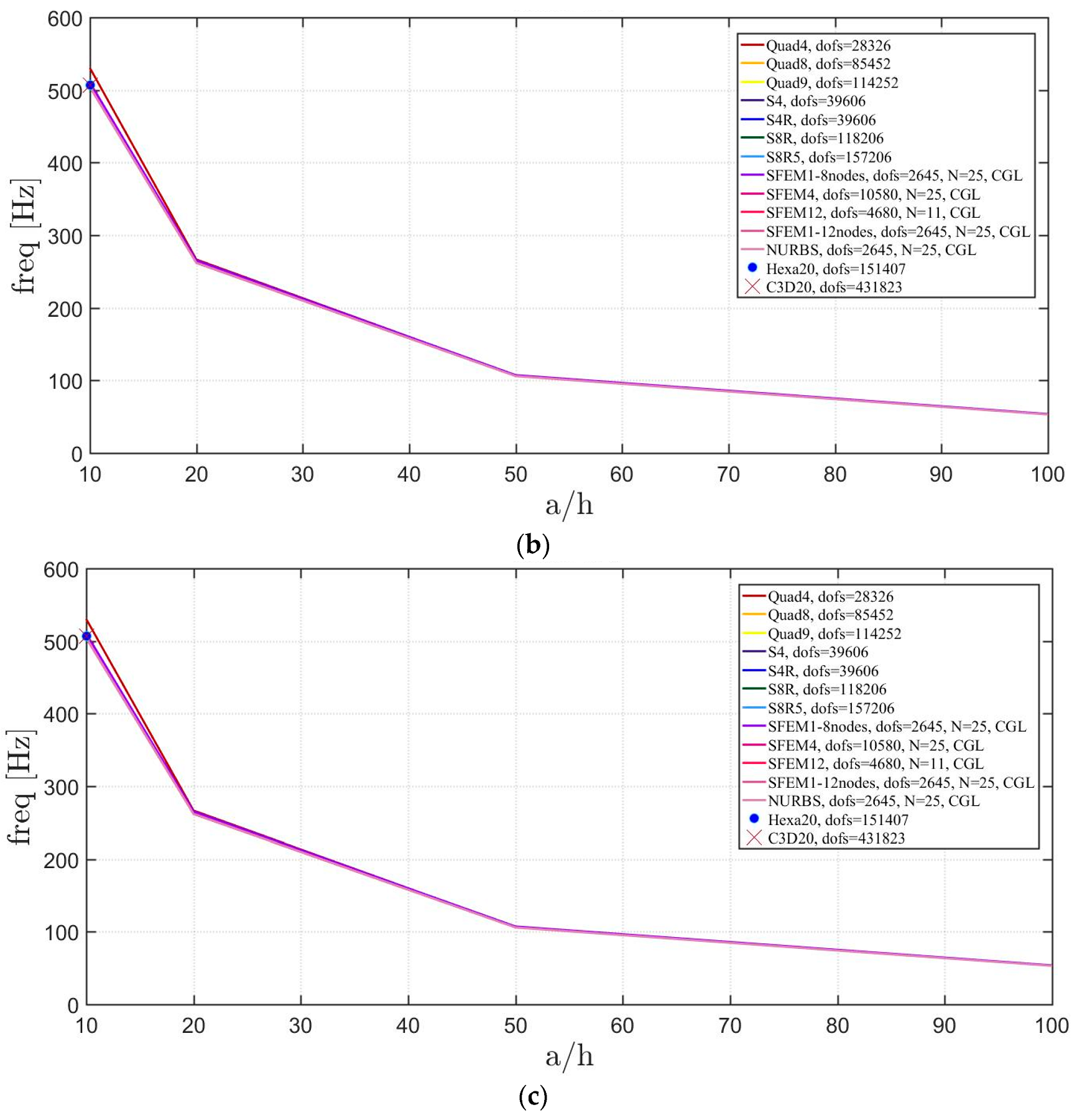
If the “thickness effect” is investigated as in the previous section, more evident discrepancies can be noted. In fact, Figure 15 and Figure 16 report the effect of the thickness by considering for symmetric and not-symmetric lamination schemes. The present accuracy error does not occur only for plates with (which identifies thick plates) but also for the other cases wherein the same error is a little bit smaller. However, it is clear that commercial FE codes show higher accuracy errors than SFEM for laminated plates with symmetric (only a few cases are present) and not-symmetric lamination schemes. By comparing the present plots with the ones corresponding to isotropic plates, a wider dispersion of the results can be observed due to the introduction of laminated composite materials.
4.2.2. Circular Plate
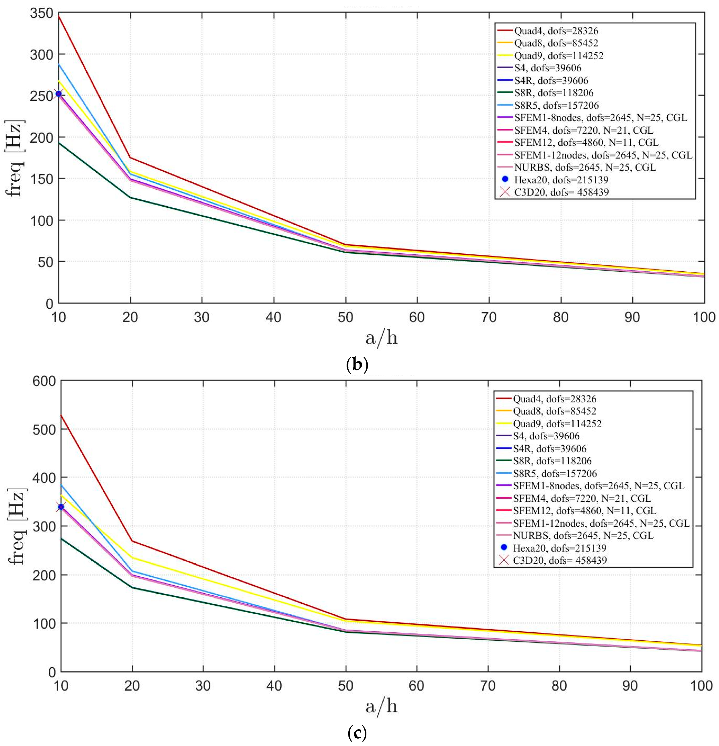
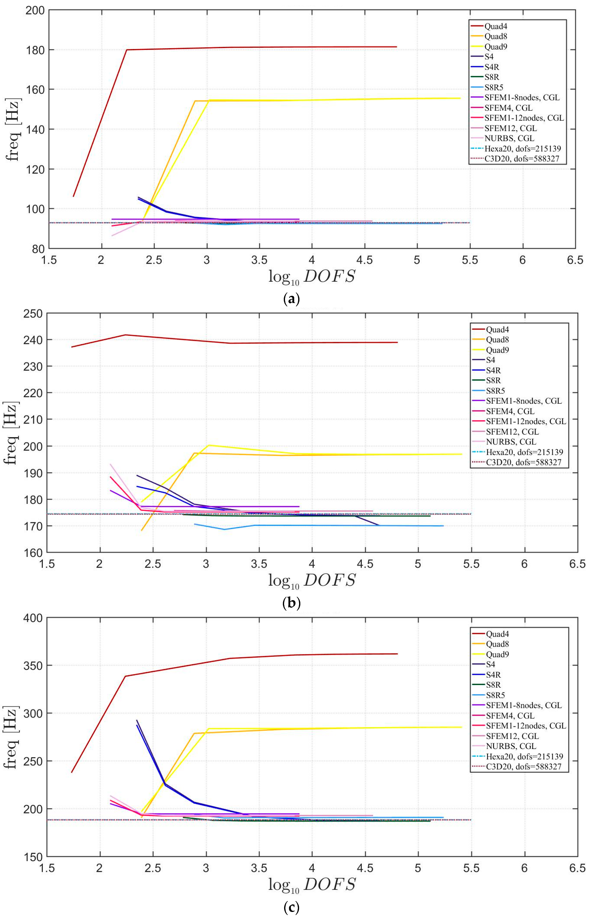
Free vibrations of clamped circular plates are described in the following. The first case has a symmetric scheme and a general one with in the second case. The orthotropic material properties are the same as the ones indicated in the previous sections. The first case is reported by Figure 17, Figure 18 and Figure 19. The convergence behavior of circular plates with symmetric lamination scheme is depicted in Figure 17 and Figure 18 for two different thickness ratios, a thin and a thick one . It can be observed that, Quad4 element from Straus7 is the less adequate element for studying the present problem. Moreover, also Quad8 and Quad9 elements have quite large differences when compared to the other solutions also for thin plates. The thickness effect on the first three natural frequencies is given in Figure 19. 3D FE models are used as reference solutions for (thick plates) with Hexa20 and C3D20 elements by Straus7 and Abaqus, respectively. Once again, the less adequate element is the Quad4, that for leads to a frequency value which is two times the reference ones.
The general lamination scheme case is depicted in Figure 20, Figure 21 and Figure 22. Convergence simulations are performed for thin and thick plates and reported in Figure 20 and Figure 21, respectively. Smaller differences are observed here if compared to the previous cases with symmetric lamination schemes, nevertheless, classical finite elements are less accurate when thick plates are considered. It is curious to observe that general purpose finite elements by Abaqus give values below the ones given by SFEM. Finally, Figure 22 shows the thickness effect for general lamination schemes.
The introduction of thick plates spread the frequencies’ values for each finite element used. The SFEM elements lead to the same accuracy as 3D FE when compared to the other 2D FE used. In fact, all the solutions are similar (within a small variance) for thin plates. On the contrary, the variation increases a lot for thick plates. In all these considerations, the single SFEM element with eight nodes has its own convergence due to the wrong geometric approximation, which has been observed in the previous sections.
4.2.3. Elliptic Plate
The elliptic plates have the same geometrical properties and meshes used in the previous sections. The lamination schemes are the same as the circular plates. In addition, three width-to-height ratios have been considered. Figure 23, Figure 24 and Figure 25 present the convergence analysis for symmetric lamination scheme one thickness ratio (because 3D FE models are more accurate for such ratios) and the three aforementioned ratios. In the present cases, Straus7 finite elements have larger differences with respect to the other solutions, and such discrepancies increase by stretching the elliptic geometry. Also in the previous case of circular plates Straus7 FE did not perform very well. This effect is more evident when the thickness effect is investigated (Figure 26, Figure 27 and Figure 28). As a matter of fact, Quad4, Quad8 and Quad9 finite elements follow a different convergence trend with respect to the others, even for smaller thicknesses such as and . The inaccuracy of some finite elements is more evident for general lamination schemes both in the convergence analyses (Figure 29, Figure 30 and Figure 31) and thickness effects (Figure 32, Figure 33 and Figure 34). In particular, general purpose Abaqus FE shows lower frequency values than the reference 3D FEM and SFEM results. Thus, they look more flexible.
The elliptic geometry underlines very well the convergence problems of the Straus7 finite element for such distortions. Abaqus FE performs well but only for thin plates. When thick plates are considered some deviations are observed in the numerical convergence.
5. Conclusions
This work deals with the stability and accuracy of two domain decomposition methods based on strong and weak formulations, respectively. The study focuses on FSDT plates of arbitrary shape as skew, circular, and elliptic plates made of isotropic and laminated composite materials. It has been discovered that, for some material configurations and plate geometry the accuracy of classic FE is significantly different from the actual solution, which is obtained through 3D FE models. On the contrary, SFEM shows natural frequencies that are very close to the given references. This work wants to shed light on the stability and accuracy of classic FE models that might give inaccurate results for peculiar plate configurations.
Acknowledgments
The research topic is one of the subjects of the Centre of Study and Research for the Identification of Materials and Structures (CIMEST)—“M. Capurso” of the University of Bologna (Italy).
Author Contributions
Nicholas Fantuzzi, Francesco Tornabene, Michele Bacciocchi, and Antonio J.M. Ferreira contributed equally to this work.
Conflicts of Interest
The authors declare no conflict of interest. The founding sponsors had no role in the design of the study; in the collection, analyses, or interpretation of data; in the writing of the manuscript, and in the decision to publish the results.
References
- Mindlin, R.D. Influence of rotatory inertia and shear on flexural motions of isotropic, elastic plates. ASME J. Appl. Mech. 1951, 18, 31–38. [Google Scholar]
- Reissner, E. The effect of transverse shear deformation on the bending of elastic plates. ASME J. Appl. Mech. 1945, 12, 68–77. [Google Scholar]
- Srinivas, S.; Joga Rao, C.V.; Rao, A.K. An exact analysis for vibration of simply supported homogeneous and laminated thick rectangular plates. J. Sound Vib. 1970, 12, 187–199. [Google Scholar] [CrossRef]
- Nelson, H.M. High frequency flexural vibration of thick rectangular bars and plates. J. Sound Vib. 1978, 60, 101–118. [Google Scholar] [CrossRef]
- Ali, R.; Atwal, S.J. Prediction of natural frequencies of vibration of rectangular plates with rectangular cutouts. Comput. Struct. 1980, 12, 819–823. [Google Scholar] [CrossRef]
- Lee, H.P.; Lim, S.P. Free vibration of isotropic and orthotropic square plates with square cutouts subjected to in-plane forces. Comput. Struct. 1992, 43, 431–437. [Google Scholar] [CrossRef]
- Farsa, J.; Kukreti, A.R.; Bert, C.W. Fundamental frequency analysis of laminated rectangular plates by differential quadrature method. Int. J. Numer. Methods Eng. 1993, 36, 2341–2356. [Google Scholar] [CrossRef]
- Farsa, J.; Kukreti, A.R.; Bert, C.W. Fundamental frequency analysis of single specially orthotropic, generally orthotropic and anisotropic rectangular layered plates by the differential quadrature method. Comput. Struct. 1993, 46, 465–477. [Google Scholar] [CrossRef]
- Bardell, N.S.; Dunsdon, J.M.; Langley, R.S. Free vibration analysis of thin coplanar rectangular plate assemblies-Part 1: Theory and initial results for specially orthotropic plates. Compos. Struct. 1996, 34, 129–143. [Google Scholar] [CrossRef]
- Wang, X.; Wang, Y.L.; Chen, R.B. Static and free vibrational analysis of rectangular plates by the differential quadrature element method. Commun. Numer. Methods Eng. 1998, 14, 1133–1141. [Google Scholar] [CrossRef]
- Huang, M.; Sakiyama, T. Free vibration analysis of rectangular plates with variously shaped holes. J. Sound Vib. 1999, 226, 769–786. [Google Scholar] [CrossRef]
- Karami, G.; Malekzadeh, P. Application of a new differential quadrature methodology for free vibration analysis of plates. Int. J. Numer. Methods Eng. 2003, 56, 847–868. [Google Scholar] [CrossRef]
- Liew, K.M.; Kitipornchai, S.; Leung, A.Y.T.; Lim, C.W. Analysis of the free vibration of rectangular plates with central cut-outs using the discrete Ritz method. Int. J. Mech. Sci. 2003, 45, 941–959. [Google Scholar] [CrossRef]
- Liew, K.M.; Wang, Y.Q.; Reddy, J.N. Vibration analysis of symmetrically laminated plates based on FSDT using the moving least square differential quadrature method. Comput. Methods Appl. Mech. Eng. 2003, 192, 2203–2222. [Google Scholar] [CrossRef]
- Huang, Y.Q.; Li, Q.S. Bending and buckling analysis of antisymmetric laminates using the moving least square differential quadrature method. Comput. Methods Appl. Mech. Eng. 2004, 193, 3471–3492. [Google Scholar] [CrossRef]
- Seok, J.; Tiersten, H.F.; Scarton, H.A. Free vibrations of rectangular cantilever plates. Part 1: Out-of-plane motion, J. Sound Vib. 2004, 271, 131–146. [Google Scholar]
- Singh, A.V.; Tanveer, M. Eingenvalue analysis of doubly connected plates with different configurations. J. Sound Vib. 2006, 295, 76–93. [Google Scholar] [CrossRef]
- Shu, C.; Wu, W.X.; Ding, H.; Wang, C.M. Free vibration analysis of plates using least-square-based finite difference method. Comput. Methods Appl. Mech. Eng. 2007, 196, 1330–1343. [Google Scholar] [CrossRef]
- Houmat, A. In-plane vibration of plates with curvilinear plan-forms by a trigonometrically enriched curved triangular p-element. Thin-Walled Struct. 2008, 46, 103–111. [Google Scholar] [CrossRef]
- Secgin, A.; Sarigul, A.S. Free vibration analysis of symmetrically laminated thin composite plates by using Discrete Singular Convolution (DSC) approach: Algorithm and verification. J. Sound Vib. 2008, 315, 197–211. [Google Scholar] [CrossRef]
- Bui, T.Q.; Nguyen, M.N.; Zhang, C. An efficient meshfree method for vibration analysis of laminated composite plates. Comput. Mech. 2011, 48, 175–193. [Google Scholar] [CrossRef]
- Dozio, L.; Carrera, E. A variable kinematic Ritz formulation for vibration study of quadrilateral plates with arbitrary thickness. J. Sound Vib. 2011, 330, 4611–4632. [Google Scholar] [CrossRef]
- Dozio, L.; Carrera, E. Ritz analysis of vibrating rectangular and skew multilayered plates based on advanced variable-kinematic models. Compos. Struct. 2012, 94, 2118–2128. [Google Scholar] [CrossRef]
- Eftekhari, S.A.; Jafari, A.A. Modified mixed Ritz-DQ formulation for free vibration of thick rectangular and skew plates with general boundary conditions. Appl. Math. Model. 2013, 37, 7398–7426. [Google Scholar] [CrossRef]
- Nassar, M.; Matbuly, M.S.; Ragb, O. Vibration analysis of structural elements using differential quadrature method. J. Adv. Res. 2013, 4, 93–102. [Google Scholar] [CrossRef] [PubMed]
- Kurtaran, H. Shape effect on free vibration of functionally graded plates. Int. J. Eng. Appl. Sci. 2014, 6, 52–67. [Google Scholar] [CrossRef]
- Fantuzzi, N.; Brischetto, S.; Tornabene, F.; Viola, E. 2D and 3D Shell Models for the Free Vibration Investigation of Functionally Graded Cylindrical and Spherical Panels. Compos. Struct. 2016, 154, 573–590. [Google Scholar] [CrossRef]
- Brischetto, S.; Tornabene, F.; Fantuzzi, N.; Viola, E. 3D Exact and 2D Generalized Differential Quadrature Models for Free Vibration Analysis of Functionally Graded Plates and Cylinders. Meccanica 2016, 51, 2059–2098. [Google Scholar] [CrossRef]
- Kim, J.; Reddy, J.N. A general third-order theory of functionally graded plates with modified couple stress effect and the von Kármán nonlinearity: Theory and finite element analysis. Acta Mech. 2015, 226, 2973–2998. [Google Scholar] [CrossRef]
- Tornabene, F.; Fantuzzi, N.; Bacciocchi, M.; Viola, E. Effect of Agglomeration on the Natural Frequencies of Functionally Graded Carbon Nanotube-Reinforced Laminated Composite Doubly-Curved Shells. Compos. Part B-Eng. 2016, 89, 187–218. [Google Scholar] [CrossRef]
- Tornabene, F.; Fantuzzi, N.; Bacciocchi, M. Linear Static Response of Nanocomposite Plates and Shells Reinforced by Agglomerated Carbon Nanotubes. Compos. Part B-Eng. 2017, 115, 449–476. [Google Scholar] [CrossRef]
- Fazzolari, F.A. Reissner’s Mixed Variational Theorem and variable kinematics in the modelling of laminated composite and FGM doubly-curved shells. Compos. Part B-Eng. 2016, 89, 408–423. [Google Scholar] [CrossRef]
- Fazzolari, F.A. Quasi-3D beam models for the computation of eigenfrequencies of functionally graded beams with arbitrary boundary conditions. Compos. Struct. 2016, 154, 239–255. [Google Scholar] [CrossRef]
- Tornabene, F.; Reddy, J.N. FGM and laminated doubly-curved and degenerate shells resting on nonlinear elastic foundations: A GDQ solution for static analysis with a posteriori stress and strain recovery. J. Indian Inst. Sci. 2013, 93, 635–688. [Google Scholar]
- Fantuzzi, N.; Tornabene, F.; Bacciocchi, M.; Dimitri, R. Free Vibration Analysis of Arbitrarily Shaped Functionally Graded Carbon Nanotube-Reinforced Plates. Compos. Part B-Eng. 2017, 115, 384–408. [Google Scholar] [CrossRef]
- Kumar, D.D.; Shivaprasad, G.; Hari, S.; Reddy, V.K. An experimental and numerical approach to free vibration analysis of glass/epoxy laminated composite plates. Int. J. Eng. Res. Technol. 2015, 4, 559–563. [Google Scholar]
- Claassen, R.W. Vibration of skew cantilever plates. AIAA J. 1963, 1, 1222. [Google Scholar] [CrossRef]
- Nair, P.S.; Durvasula, S. Vibration of skew plates. J. Sound Vib. 1973, 26, 1–19. [Google Scholar] [CrossRef]
- Mizusawa, T.; Kajita, T.; Naruoka, M. Vibration of skew plates by using B-spline functions. J. Sound Vib. 1979, 62, 301–308. [Google Scholar] [CrossRef]
- Raju, K.K.; Hinton, E. Natural frequencies and modes of rhombic Mindlin plates. Earthq. Eng. Struct. Dyn. 1980, 8, 55–62. [Google Scholar] [CrossRef]
- Gorman, D.J. Accurate free vibration analysis of rhombic plates with simply-supported and fully clamped edge conditions. J. Sound Vib. 1988, 125, 281–290. [Google Scholar] [CrossRef]
- Bardell, N.S. The free vibration of skew plates using the hierarchical finite element method. Comput. Struct. 1992, 45, 841–874. [Google Scholar] [CrossRef]
- Liew, K.M.; Wang, C.M. Vibration studies on skew plates: Treatment of internal line supports. Comput. Struct. 1993, 49, 941–951. [Google Scholar] [CrossRef]
- Bert, C.W.; Malik, M. The differential quadrature method for irregular domains and application to plate vibration. Int. J. Mech. Sci. 1996, 38, 589–606. [Google Scholar] [CrossRef]
- Hosokawa, K.; Terada, Y.; Sakata, T. Free vibrations of clamped symmetrically laminated skew plates. J. Sound Vib. 1996, 189, 525–533. [Google Scholar] [CrossRef]
- Han, W.; Dickinson, S. Free vibration of symmetrically laminated skew plates. J. Sound Vib. 1997, 208, 367–390. [Google Scholar] [CrossRef]
- Wang, S. Free vibration analysis of skew fiber-reinforced composite laminates based on first-order shear deformation plate theory. Comput. Struct. 1997, 63, 525–538. [Google Scholar] [CrossRef]
- Wang, S. Vibration of thin skew fiber-reinforced composite laminates. J. Sound Vib. 1997, 201, 335–352. [Google Scholar] [CrossRef]
- Skeikh, A.H.; Haldar, S.; Sengupta, D. Vibration of plates in different situations using a high-precision shear deformable element. J. Sound Vib. 2002, 253, 329–345. [Google Scholar] [CrossRef]
- Karami, G.; Malekzadeh, P. An efficient differential quadrature methodology for free vibration analysis of arbitrary straight-sided quadrilateral thin plates. J. Sound Vib. 2003, 263, 415–442. [Google Scholar] [CrossRef]
- Karami, G.; Malekzadeh, P.; Ali Shahpari, S. DQM analysis of skewed and trapezoidal laminated plates. Compos. Struct. 2003, 59, 393–402. [Google Scholar] [CrossRef]
- Liew, K.M.; Wang, J.; Ng, T.Y.; Tan, M.J. Free vibration and buckling analysis of shear-deformable plates based on FSDT meshfree method. J. Sound Vib. 2004, 276, 997–1017. [Google Scholar] [CrossRef]
- Garg, A.K.; Khare, R.K.; Kant, T. Free vibration of skew fiber-reinforced composite and sandwich laminates using a shear deformable finite element model. J. Sandw. Struct. Mater. 2006, 8, 33–53. [Google Scholar] [CrossRef]
- Civalek, O. Discrete singular convolution methodology for free vibration and stability analyses of arbitrary straight-sided quadrilateral plates. Commun. Numer. Methods Eng. 2008, 24, 1475–1495. [Google Scholar] [CrossRef]
- Das, D.; Sahoo, P.; Saha, K. Large-amplitude dynamic analysis of simply supported skew plates by a variational method. J. Sound Vib. 2008, 313, 246–267. [Google Scholar] [CrossRef]
- Nallim, L.G.; Oller, S. An analytical-numerical approach to simulate the dynamic behavior of arbitrarily laminated composite plates. Compos. Struct. 2008, 85, 311–325. [Google Scholar] [CrossRef]
- Zhou, L.; Zheng, W.X. Vibration of skew plates by the MLS-Ritz method. Int. J. Mech. Sci. 2008, 50, 1133–1141. [Google Scholar] [CrossRef]
- Ashour, A.S. The free vibration of symmetrically angle-ply laminated fully clamped skew plates. J. Sound Vib. 2009, 323, 444–450. [Google Scholar] [CrossRef]
- Gurses, M.; Civalek, O.; Korkmaz, A.K.; Ersoy, H. Free vibration analysis of symmetric laminated skew plates by discrete singular convolution technique based on first-order shear deformation theory. Int. J. Numer. Methods Eng. 2009, 79, 290–313. [Google Scholar] [CrossRef]
- Rao, K.D.; Babu, K.S. Modal analysis of thin FRP skew symmetric angle-ply laminate with circular cut-out. Int. J. Eng. Res. Technol. 2012, 1, 1–5. [Google Scholar]
- Srinivasa, C.V.; Suresh, Y.J.; Prema Kumar, W.P. Free flexural vibration studies on laminated composite skew plates. Int. J. Eng. Sci. Technol. 2012, 4, 13–24. [Google Scholar] [CrossRef]
- Wang, X.; Wu, Z. Differential quadrature analysis of free vibration of rhombic plates with free edges. Appl. Math. Comput. 2013, 225, 171–183. [Google Scholar] [CrossRef]
- Zhang, L.W.; Xiao, L.N. Mechanical behavior of laminated CNT-reinforced composite skew plates subjected to dynamic loading. Compos. Part B-Eng. 2017, 122, 219–230. [Google Scholar] [CrossRef]
- Zhang, L.W. On the study of the effect of in-plane forces on the frequency parameters of CNT-reinforced composite skew plates. Compos. Struct. 2017, 160, 824–837. [Google Scholar] [CrossRef]
- Wang, X.; Wang, Y.; Yuan, Z. Accurate vibration analysis of skew plates by the new version of the differential quadrature method. Appl. Math. Model. 2014, 38, 926–937. [Google Scholar] [CrossRef]
- Mohazzab, A.H.; Dozio, L. A spectral collocation solution for in-plane eigenvalue analysis of skew plates. Int. J. Mech. Sci. 2015, 94–95, 199–210. [Google Scholar] [CrossRef]
- Ramakrishnan, R.; Kunukasseril, V.X. Free vibration of stiffened circular bridge decks. J. Sound Vib. 1976, 44, 209–221. [Google Scholar] [CrossRef]
- Irie, T.; Yamada, G.; Ito, F. Free vibration of polar-orthotropic sector plates. J. Sound Vib. 1979, 67, 89–100. [Google Scholar] [CrossRef]
- Irie, T.; Yamada, G.; Ito, F. Flexural vibrations of polar-orthotropic sector plates with simply-supported straight edges. J. Sound Vib. 1980, 70, 589–596. [Google Scholar]
- Maruyama, K.; Ichinomiya, O. Experimental investigation of free vibrations of clamped sector plates. J. Sound Vib. 1981, 74, 565–573. [Google Scholar] [CrossRef]
- Srinivasan, R.S.; Thiruvenkatachari, V. Free vibration of annular sector plates by an integral equation technique. J. Sound Vib. 1983, 89, 425–432. [Google Scholar] [CrossRef]
- Srinivasan, R.S.; Thiruvenkatachari, V. Free vibration of transverse isotropic annular sector Mindlin plates. J. Sound Vib. 1985, 101, 193–201. [Google Scholar] [CrossRef]
- Harik, I.E.; Molaghasemi, H.R. Analytical solution to free vibration of sector plates. J. Eng. Mech. 1989, 115, 2709–2722. [Google Scholar] [CrossRef]
- Mizusawa, T.; Kajita, T. Vibration of annular sector plates using spline strip method. Commun. Appl. Numer. Methods 1992, 8, 537–546. [Google Scholar] [CrossRef]
- Mizusawa, T.; Takami, K. Vibration of tapered thickness annular sector plates by spline element method. J. Sound Vib. 1992, 154, 147–160. [Google Scholar] [CrossRef]
- Liew, K.M.; Lam, K.Y. On the use of 2D orthogonal polynomials in the Rayleigh-Ritz method for flexural vibration of annular sector plates of arbitrary shape. Int. J. Mech. Sci. 1993, 35, 129–139. [Google Scholar] [CrossRef]
- Xiang, Y.; Liew, K.M.; Kitipornchai, S. Transverse vibration of thick annular sector plates. J. Eng. Mech. 1993, 1579–1599. [Google Scholar] [CrossRef]
- McGee, O.G.; Huang, C.S.; Leissa, A.W. Comprehensive exact solutions for free vibrations of thick annular sectorial plates with simply supported radial edges. Int. J. Mech. Sci. 1995, 37, 537–566. [Google Scholar] [CrossRef]
- McGee, O.G.; Huang, C.S.; Leissa, A.W.; Kim, J.W. Vibrations of circular plates with clamped V-notches or rigidly constrained radial cracks. J. Sound Vib. 1995, 181, 185–201. [Google Scholar] [CrossRef]
- Liew, K.M.; Han, J.B.; Xiao, Z.M. Vibration analysis of circular Mindlin plates using the differential quadrature method. J. Sound Vib. 1997, 205, 617–630. [Google Scholar] [CrossRef]
- Liu, F.L.; Liew, K.M. Free vibration analysis of Mindlin sector plate: Numerical solutions by differential quadrature method. Comput. Methods Appl. Mech. Eng. 1999, 177, 77–92. [Google Scholar] [CrossRef]
- Liu, F.L.; Liew, K.M. Differential quadrature element method: A new approach for free vibration analysis of polar Mindlin plates having discontinuities. Comput. Methods Appl. Mech. Eng. 1999, 179, 407–423. [Google Scholar] [CrossRef]
- Liu, F.L.; Liew, K.M. Differential quadrature element method for static analysis of Reissner-Mindlin polar plates. Int. J. Solids Struct. 1999, 36, 5101–5123. [Google Scholar] [CrossRef]
- Liu, F.L.; Liew, K.M. Differential quadrature method for vibration analysis of shear deformable annular sector plates. J. Sound Vib. 2000, 230, 335–356. [Google Scholar]
- Zhong, H. Application of triangular differential quadrature to problems with curved boundaries. Commun. Numer. Methods Eng. 2002, 18, 633–643. [Google Scholar] [CrossRef]
- Civalek, O.; Catal, H.H. Linear static and vibration analysis of circular and annular plates by the Harmonic Differential Quadrature (HDQ) method. Eng. Arch. Fac. Osmangazi Univ. 2003, 17, 44–71. [Google Scholar]
- Liew, K.M.; Huang, Y.Q.; Reddy, J.N. Analysis of general shaped thin plates by the moving least-squares differential quadrature method. Finite Elem. Anal. Des. 2004, 40, 1453–1474. [Google Scholar] [CrossRef]
- Sharma, A.; Sharda, H.B.; Nath, Y. Stability and vibration of Mindlin sector plates: An analytical approach. AIAA J. 2005, 43, 1109–1116. [Google Scholar] [CrossRef]
- Nie, G.J.; Zhong, Z. Semi-analytical solution for three-dimensional vibration of functionally graded circular plates. Comput. Methods Appl. Mech. Eng. 2007, 196, 4901–4910. [Google Scholar] [CrossRef]
- Dong, C.Y. Three-Dimensional free vibration analysis of functionally graded annular plates using the Chebyshev-Ritz method. Mater. Des. 2008, 29, 1518–1525. [Google Scholar] [CrossRef]
- Civalek, O. Use of eight-node curvilinear domains in discrete singular convolution method for free vibration analysis of annular sector plates with simply supported radial edges. J. Vib. Control 2009, 16, 303–320. [Google Scholar] [CrossRef]
- Civalek, O. Numerical solutions to the free vibration problem of Mindlin sector plates using the discrete singular convolution method. Int. J. Struct. Stab. Dyn. 2009, 9, 267–284. [Google Scholar] [CrossRef]
- Xing, Y.; Liu, B. High-accuracy differential quadrature finite element method and its application to free vibration of thin plate with curvilinear domain. Int. J. Numer. Methods Eng. 2009, 80, 1718–1742. [Google Scholar] [CrossRef]
- Zhou, D.; Lo, S.H.; Cheung, Y.K. 3-D vibration analysis of plates with curvilinear quadrilateral domains by discrete singular convolution method. J. Sound Vib. 2009, 320, 421–437. [Google Scholar] [CrossRef]
- Civalek, O.; Ozturk, B. Vibration analysis of plates with curvilinear quadrilateral domains by discrete singular convolution method. Struct. Eng. Mech. 2010, 36, 279–299. [Google Scholar] [CrossRef]
- Lam, K.Y.; Liew, K.M.; Chow, S.T. Free vibration analysis of isotropic and orthotropic triangular plates. Int. J. Mech. Sci. 1990, 32, 455–464. [Google Scholar] [CrossRef]
- Dubliner, M. Spectral methods on triangles and other domains. J. Sci. Comput. 1991, 6, 345–390. [Google Scholar] [CrossRef]
- Kitipornchai, S.; Liew, K.M.; Xiang, Y.; Wang, C.M. Free vibration of isosceles triangular Mindlin plates. Int. J. Mech. Sci. 1993, 35, 89–102. [Google Scholar] [CrossRef]
- Mirza, S.; Alizadeh, Y. Free vibration of partially supported triangular plates. Comput. Struct. 1994, 51, 143–150. [Google Scholar] [CrossRef]
- Qatu, M.S. Natural frequencies for cantilevered laminated composite right triangular and trapezoidal plates. Compos. Sci. Technol. 1994, 51, 441–449. [Google Scholar] [CrossRef]
- Abrate, S. Vibration of point supported triangular plates. Comput. Struct. 1996, 58, 327–336. [Google Scholar] [CrossRef]
- Karunasena, W.; Kitipornchai, S.; Al-Bermani, F.G.A. Free vibration of cantilevered arbitrary triangular Mindlin plates. Int. J. Mech. Sci. 1996, 38, 431–442. [Google Scholar] [CrossRef]
- Singh, B.; Saxena, V. Transverse vibration of triangular plates with variable thickness. J. Sound Vib. 1996, 194, 471–496. [Google Scholar] [CrossRef]
- Karunasena, W.; Kitipornchai, S. Free vibration of shear-deformable general triangular plates. J. Sound Vib. 1997, 199, 595–613. [Google Scholar] [CrossRef]
- Singh, B.; Hassan, S.M. Transverse vibration of triangular plates with arbitrary thickness variation and various boundary conditions. J. Sound Vib. 1998, 214, 29–55. [Google Scholar] [CrossRef]
- Sakiyama, T.; Huang, M. Free vibration analysis of right triangular plates with variable thickness. J. Sound Vib. 2000, 234, 841–858. [Google Scholar] [CrossRef]
- Zhong, H.Z. Free vibration analysis of isosceles triangular Mindlin plates by the triangular differential quadrature method. J. Sound Vib. 2000, 237, 697–708. [Google Scholar] [CrossRef]
- Sheikh, A.H.; Haldar, S.; Sengupta, D. A high precision shear deformable element for the analysis of laminated composite plates of different shapes. Compos. Struct. 2002, 55, 329–336. [Google Scholar] [CrossRef]
- Civalek, O.; Gurses, M. Frequency analysis of trapezoidal plates and membrane using discrete singular convolution. Asian J. Civ. Eng. 2009, 9, 593–605. [Google Scholar]
- El-Sayad, M.A.; Ghazy, S.S.A. Rayleigh-Ritz method for free vibration of Mindlin trapezoidal plates. Can. J. Sci. Eng. Math. 2012, 3, 271–278. [Google Scholar]
- Quintana, M.V.; Nallim, L.G. A general Ritz formulation for the vibration analysis of thick trapezoidal and triangular laminated plates resting on elastic supports. Int. J. Mech. Sci. 2013, 69, 1–9. [Google Scholar] [CrossRef]
- Rango, R.F.; Nallim, L.G.; Oller, S. Static and dynamic analysis of thick laminated plates using enriched macroelements. Compos. Struct. 2013, 101, 94–103. [Google Scholar] [CrossRef]
- Rango, R.F.; Nallim, L.G.; Oller, S. Formulation of enriched macro elements using trigonometric shear deformation theory for free vibration analysis of symmetric laminated composite plate assemblies. Compos. Struct. 2015, 119, 38–49. [Google Scholar] [CrossRef]
- Singh, B.; Chakraverty, S. On the use of orthogonal polynomials in the Rayleigh-Ritz method for the study of transverse vibration of elliptic plates. Comput. Struct. 1992, 43, 439–443. [Google Scholar] [CrossRef]
- Chakraverty, S.; Jindal, R.; Agarwal, V.K. Flexural vibrations of non-homogeneous elliptic plates. Indian J. Eng. Mater. Sci. 2005, 12, 521–528. [Google Scholar]
- Ghazy, S.S.A.; Barki, F.A.; Safwat, H.M. Free vibration analysis of penta, hepta-gonal shaped plates. Comput. Struct. 1997, 62, 395–407. [Google Scholar] [CrossRef]
- Lim, C.W.; Liew, K.M. Vibrations of perforated plates with rounded corners. J. Eng. Mech. 1995, 121, 203–213. [Google Scholar] [CrossRef]
- Liu, G.R.; Zhao, X.; Dai, K.Y.; Zhong, Z.H.; Li, G.Y.; Han, X. Static and free vibration analysis of laminated composite plates using the conforming radial point interpolation method. Compos. Sci. Technol. 2008, 68, 354–366. [Google Scholar] [CrossRef]
- Lam, K.Y.; Liew, K.M.; Chow, S.T. Use of two-dimensional orthogonal polynomials for vibration analysis of circular and elliptical plates. J. Sound Vib. 1992, 154, 261–269. [Google Scholar] [CrossRef]
- Leissa, A.W. Vibration of Plates; NASA Sp–160; US Government Printing Office: Washington, DC, USA, 1969.
- Ferreira, A.J.M.; Roque Jorge, R.M.N. Free vibration analysis of symmetric laminated composite plates by FSDT and radial basis functions. Comput. Methods Appl. Mech. Eng. 2005, 194, 4265–4278. [Google Scholar] [CrossRef]
- Anlas, G.; Göker, G. Vibration analysis of skew fibre-reinforced composite laminated plates. J. Sound Vib. 2001, 242, 265–276. [Google Scholar] [CrossRef]
- Murthy, M.V.V. An Improved Transverse Shear Deformation Theory for Laminated Anisotropic Plates; NASA Technical Paper; National Aeronautics and Space Administration (NASA): Washington, DC, USA, 1981.
- Green, A.E.; Naghdi, P.M. A theory of composite laminated plates. IMA J. Appl. Math. 1982, 29, 1–23. [Google Scholar] [CrossRef]
- Bert, C.W. A Critical Evaluation of New Plate Theories Applied to Laminated Composites. Compos. Struct. 1984, 2, 329–347. [Google Scholar] [CrossRef]
- Reddy, J.N. A Simple Higher-Order Theory for Laminated Composite Plates. J. Appl. Mech. ASME 1984, 51, 745–752. [Google Scholar] [CrossRef]
- Shirakawa, K. Bending of plates based on improved theory. Mech. Res. Commun. 1985, 10, 205–211. [Google Scholar] [CrossRef]
- Reddy, J.N. A Generalization of the Two-Dimensional Theories of Laminated Composite Plates. Commun. Appl. Numer. Methods 1987, 3, 173–180. [Google Scholar] [CrossRef]
- Reddy, J.N. On Refined Theories of Composite Laminates. Meccanica 1990, 25, 230–238. [Google Scholar] [CrossRef]
- Robbins, D.H.; Reddy, J.N. Modeling of Thick Composites Using a Layer-Wise Laminate Theory. Int. J. Numer. Methods Eng. 1993, 36, 655–677. [Google Scholar] [CrossRef]
- Alibeiglooa, A.; Shakeri, M.; Kari, M.R. Free vibration analysis of antisymmetric laminated rectangular plates with distributed patch mass using third-order shear deformation theory. Ocean Eng. 2008, 35, 183–190. [Google Scholar] [CrossRef]
- Xiang, S.; Wang, K.-M. Free vibration analysis of symmetric laminated composite plates by trigonometric shear deformation theory and inverse multiquadric RBF. Thin Walled Struct. 2009, 47, 304–310. [Google Scholar] [CrossRef]
- Groh, R.M.J.; Weaver, P.M. A computationally efficient 2D model for inherently equilibrated 3D stress predictions in heterogeneous laminated plates. Part I: Model formulation. Compos. Struct. 2016, 156, 171–185. [Google Scholar] [CrossRef]
- Groh, R.M.J.; Weaver, P.M. A computationally efficient 2D model for inherently equilibrated 3D stress predictions in heterogeneous laminated plates. Part II: Model validation. Compos. Struct. 2016, 156, 186–217. [Google Scholar] [CrossRef]
- Wang, Y.; Shi, G.; Wang, X. Displacement and stress analysis of laminated composite plates using an eight-node quasi-conforming solid-shell element. Curved Layer. Struct. 2017, 8–20. [Google Scholar] [CrossRef]
- Neves, A.M.A.; Ferreira, A.J.M. Free vibrations and buckling analysis of laminated plates by oscillatory radial basis functions. Curved Layer. Struct. 2016, 3, 17–21. [Google Scholar] [CrossRef]
- Wang, Q.; She, D.; Pang, F.; Liang, Q. Vibrations of Composite Laminated Circular Panels and Shells of Revolution with General Elastic Boundary Conditions via Fourier-Ritz Method. Curved Layer. Struct. 2016, 3, 105–136. [Google Scholar] [CrossRef]
- Piskunov, V.G.; Verijenko, V.E.; Adali, S.; Summers, E.B. A Higher-order Theory for the Analysis of Laminated Plates and Shells with Shear and Normal Deformation. Int. J. Eng. Sci. 1993, 31, 967–988. [Google Scholar] [CrossRef]
- Brischetto, S. An exact 3D solution for free vibrations of multilayered cross-ply composite and sandwich plates and shells. Int. J. Appl. Mech. 2014, 6, 1450076. [Google Scholar] [CrossRef]
- Brischetto, S.; Torre, R. Exact 3D solutions and finite element 2D models for free vibration analysis of plates and cylinders. Curved Layer. Struct. 2014, 1, 59–92. [Google Scholar] [CrossRef]
- Whitney, J.M.; Pagano, N.J. Shear Deformation in Heterogeneous Anisotropic Plates. J. Appl. Mech. ASME 1970, 37, 1031–1036. [Google Scholar] [CrossRef]
- Whitney, J.M.; Sun, C.T. A Higher Order Theory for Extensional Motion of Laminated Composites. J. Sound Vib. 1973, 30, 85–97. [Google Scholar] [CrossRef]
- Thai, H.-T.; Kim, S.-E. Free vibration of laminated composite plates using two variable refined plate theory. Int. J. Mech. Sci. 2010, 52, 626–633. [Google Scholar] [CrossRef]
- Sahoo, R.; Singh, B.N. A new trigonometric zigzag theory for buckling and free vibration analysis of laminated composite and sandwich plates. Compos. Struct. 2014, 117, 316–332. [Google Scholar] [CrossRef]
- Vidal, P.; Polit, O.; D’Ottavio, M.; Valot, E. Assessment of the refined sinus plate finite element: Free edge effect and Meyer-Piening sandwich test. Finite Elem. Anal. Des. 2014, 92, 60–71. [Google Scholar] [CrossRef]
- Wang, X.; Shi, G. A refined laminated plate theory accounting for the third-order shear deformation and interlaminar transverse stress continuity. Appl. Math. Model. 2015, 39, 5659–5680. [Google Scholar] [CrossRef]
- Zuo, H.; Yang, Z.; Chen, X.; Xie, Y.; Miao, H. Analysis of laminated composite plates using wavelet finite element method and higher-order plate theory. Compos. Struct. 2015, 131, 248–258. [Google Scholar] [CrossRef]
- Malekzadeh, P.; Afsari, A.; Zahedinejad, P.; Bahadori, R. Three-dimensional layerwise-finite element free vibration analysis of thick laminated annular plates on elastic foundation. Appl. Math. Model. 2010, 34, 776–790. [Google Scholar] [CrossRef]
- Mantari, J.L.; Oktem, A.S.; Guedes Soares, C. A new trigonometric layerwise shear deformation theory for the finite element analysis of laminated composite and sandwich plates. Comput. Struct. 2012, 94–95, 45–53. [Google Scholar] [CrossRef]
- Thai, C.H.; Ferreira, A.J.M.; Carrera, E.; Nguyen-Xuan, H. Isogeometric analysis of laminated composite and sandwich plates using a layerwise deformation theory. Compos. Struct. 2013, 104, 196–214. [Google Scholar] [CrossRef]
- Mantari, J.L.; Soares, C.G. Generalized layerwise HSDT and finite element formulation for symmetric laminated and sandwich composite plates. Compos. Struct. 2013, 105, 319–331. [Google Scholar] [CrossRef]
- Guo, Y.; Nagy, A.P.; Gürdal, Z. A layerwise theory for laminated composites in the framework of isogeometric analysis. Compos. Struct. 2014, 107, 447–457. [Google Scholar] [CrossRef]
- Boscolo, M.; Banerjee, J.R. Layer-wise dynamic stiffness solution for free vibration analysis of laminated composite plates. J. Sound Vib. 2014, 333, 200–227. [Google Scholar] [CrossRef]
- Yazdani, S.; Ribeiro, P. A layerwise p-version finite element formulation for free vibration analysis of thick composite laminates with curvilinear fibres. Compos. Struct. 2015, 120, 531–542. [Google Scholar] [CrossRef]
- Band, U.N.; Desai, Y.M. Coupled higher order and mixed layerwise finite element based static and free vibration analyses of laminated plates. Compos. Struct. 2015, 128, 406–414. [Google Scholar] [CrossRef]
- Biscani, F.; Giunta, G.; Belouettar, S.; Hu, H.; Carrera, E. Mixed-dimensional modeling by means of solid and higher-order multi-layered plate finite elements. Mech. Adv. Mater. Struct. 2016, 23, 960–970. [Google Scholar] [CrossRef]
- Tornabene, F.; Fantuzzi, N.; Bacciocchi, M. The GDQ Method for the Free Vibration Analysis of Arbitrarily Shaped Laminated Composite Shells Using a NURBS-Based Isogeometric Approach. Compos. Struct. 2016, 154, 190–218. [Google Scholar] [CrossRef]
- Bacciocchi, M.; Eisenberger, M.; Fantuzzi, N.; Tornabene, F.; Viola, E. Vibration Analysis of Variable Thickness Plates and Shells by the Generalized Differential Quadrature Method. Compos. Struct. 2016, 156, 218–237. [Google Scholar] [CrossRef]
- Vescovini, R.; Dozio, L. A variable-kinematic model for variable stiffness plates: Vibration and buckling analysis. Compos. Struct. 2016, 142, 15–26. [Google Scholar] [CrossRef]
- Wenzel, C.; D’Ottavio, M.; Polit, O.; Vidal, P. Assessment of free-edge singularities in composite laminates using higher-order plate elements. Mech. Adv. Mater. Struct. 2016, 23, 948–959. [Google Scholar] [CrossRef]
- Tornabene, F.; Fantuzzi, N.; Bacciocchi, M.; Viola, E. Accurate Inter-Laminar Recovery for Plates and Doubly-Curved Shells with Variable Radii of Curvature Using Layer-Wise Theories. Compos. Struct. 2015, 124, 368–393. [Google Scholar] [CrossRef]
- Tornabene, F.; Fantuzzi, N.; Bacciocchi, M. Higher-Order Structural Theories for the Static Analysis of Doubly-Curved Laminated Composite Panels Reinforced by Curvilinear Fibers. Thin-Walled Struct. 2016, 102, 222–245. [Google Scholar] [CrossRef]
- Tornabene, F. General Higher Order Layer-Wise Theory for Free Vibrations of Doubly-Curved Laminated Composite Shells and Panels. Mech. Adv. Mater. Struct. 2016, 23, 1046–1067. [Google Scholar] [CrossRef]
- Demasi, L. ∞3 Hierarchy plate theories for thick and thin composite plates: The generalized unified formulation. Compos. Struct. 2008, 84, 256–270. [Google Scholar] [CrossRef]
- D’Ottavio, M. A Sublaminate Generalized Unified Formulation for the analysis of composite structures. Compos. Struct. 2016, 142, 187–199. [Google Scholar] [CrossRef]
- Carpinteri, A. Static-kinematic duality in beams, plates, shells and its central role in the finite element method. Curved Layer. Struct. 2017, 4, 38–51. [Google Scholar] [CrossRef]
- Chavan, S.G.; Lal, A. Bending analysis of laminated SWCNT Reinforced functionally graded plate using FEM. Curved Layer. Struct. 2017, 4, 134–145. [Google Scholar] [CrossRef]
- Demir, Ç.; Ersoy, H.; Mercan, K.; Civalek, Ö. Free vibration analysis of annular sector plates via conical shell equations. Curved Layer. Struct. 2017, 4, 146–157. [Google Scholar] [CrossRef]
- Pang, F.; Li, H.; Miao, X.; Wang, X. A modified Fourier solution for vibration analysis of moderately thick laminated annular sector plates with general boundary conditions, internal radial line and circumferential arc supports. Curved Layer. Struct. 2017, 189–220. [Google Scholar] [CrossRef]
- Thai, C.H.; Xuan, N.H.; Thanh, N.N.; Le, T.-H.; Thoi, N.T.; Rabczuk, T. Static, free vibration, and buckling analysis of laminated composite Reissner-Mindlin plates using NURBS-based isogeometric approach. Int. J. Numer. Methods Eng. 2012, 91, 571–603. [Google Scholar] [CrossRef]
- Nguyen, V.P.; Hung, N.-X. High-order B-splines based finite elements for delamination analysis of laminated composites. Compos. Struct. 2013, 102, 261–275. [Google Scholar] [CrossRef]
- Wang, Y.; Waisman, H. Progressive delamination analysis of composite materials using XFEM and a discrete damage zone model. Comput. Mech. 2015, 55, 1–26. [Google Scholar] [CrossRef]
- Li, D.H. Extended layerwise method of laminated composite shells. Compos. Struct. 2016, 136, 313–344. [Google Scholar] [CrossRef]
- Tornabene, F.; Fantuzzi, N.; Bacciocchi, M.; Viola, E. Laminated Composite Doubly-Curved Shell Structures. Differential Geometry Higher-Order Structural Theories, 1st ed.; Società Editrice Esculapio: Bologna, Italy, 2016. [Google Scholar]
- Tornabene, F.; Fantuzzi, N.; Bacciocchi, M.; Viola, E. Laminated Composite Doubly-Curved Shell Structures. Differential and Integral Quadrature. Strong Formulation Finite Element Method, 1st ed; Società Editrice Esculapio: Bologna, Italy, 2016. [Google Scholar]
- Tornabene, F.; Fantuzzi, N.; Ubertini, F.; Viola, E. Strong formulation finite element method based on differential quadrature: A survey. Appl. Mech. Rev. 2015, 67, 020801. [Google Scholar] [CrossRef]
- Ferreira, A.J.M.; Carrera, E.; Cinefra, M.; Viola, E.; Tornabene, F.; Fantuzzi, N.; Zenkour, A.M. Analysis of Thick Isotropic and Cross-Ply Laminated Plates by Generalized Differential Quadrature Method and a Unified Formulation. Compos. Part B-Eng. 2014, 58, 544–552. [Google Scholar] [CrossRef]
- Tornabene, F.; Fantuzzi, N.; Bacciocchi, M. The Strong Formulation Finite Element Method: Stability and Accuracy. Fract. Struct. Integr. 2014, 29, 251–265. [Google Scholar]
- Fantuzzi, N.; Bacciocchi, M.; Tornabene, F.; Viola, E.; Ferreira, A.J.M. Radial Basis Functions Based on Differential Quadrature Method for the Free Vibration of Laminated Composite Arbitrary Shaped Plates. Compos. Part B-Eng. 2015, 78, 65–78. [Google Scholar] [CrossRef]
- Fantuzzi, N.; Tornabene, F. Strong Formulation Isogeometric Analysis (SFIGA) for Laminated Composite Arbitrarily Shaped Plates. Compos. Part B-Eng. 2016, 96, 173–203. [Google Scholar] [CrossRef]
- Tornabene, F.; Fantuzzi, N.; Bacciocchi, M.; Neves, A.M.A.; Ferreira, A.J.M. MLSDQ Based on RBFs for the Free Vibrations of Laminated Composite Doubly-Curved Shells. Compos. Part B-Eng. 2016, 99, 30–47. [Google Scholar] [CrossRef]
- Fantuzzi, N.; Dimitri, R.; Tornabene, F. A SFEM-Based Evaluation of Mode-I Stress Intensity Factor in Composite Structures. Compos. Struct. 2016, 145, 162–185. [Google Scholar] [CrossRef]
- Dimitri, R.; Fantuzzi, N.; Tornabene, F.; Zavarise, G. Innovative Numerical Methods Based on SFEM and IGA for Computing Stress Concentrations in Isotropic Plates with Discontinuities. Int. J. Mech. Sci. 2016, 118, 166–187. [Google Scholar] [CrossRef]
- Tornabene, F.; Fantuzzi, N.; Bacciocchi, M. DiQuMASPAB: Differential Quadrature for Mechanics of Anisotropic Shells, Plates, Arches and Beams. User Manual, 1st ed.; Società Editrice Esculapio: Bologna, Italy, 2018; Available online: https://diqumaspab.editrice-esculapio.com (accessed on 2 February 2018).
Figure 1.
Geometric interpretation of the FSDT kinematic model.

Figure 2.
Stress resultants on the middle surface of the plate.
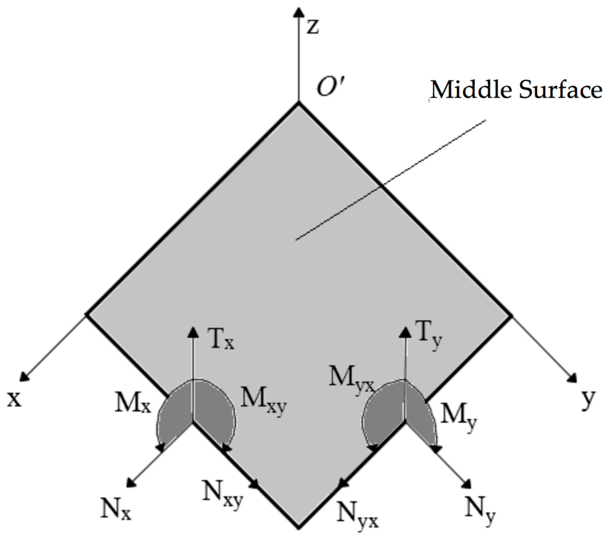
Figure 3.
First three natural frequencies an isotropic skew plate of 30°: (a) First frequency; (b) Second frequency; (c) Third frequency.
Figure 3.
First three natural frequencies an isotropic skew plate of 30°: (a) First frequency; (b) Second frequency; (c) Third frequency.
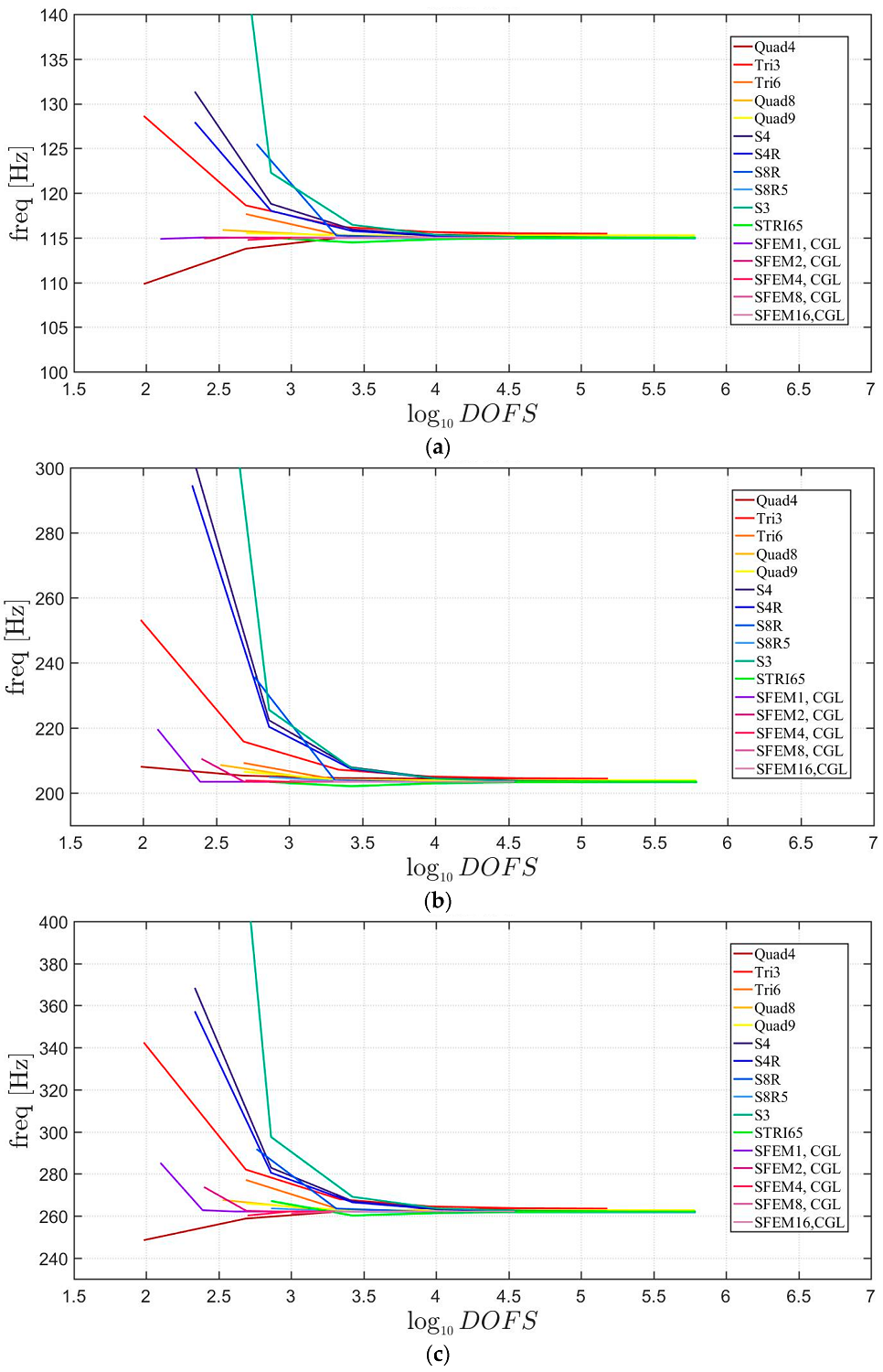
Figure 4.
Thickness effect on the first three natural frequencies of an isotropic skew plate of 30°: (a) First frequency; (b) Second frequency; (c) Third frequency.
Figure 4.
Thickness effect on the first three natural frequencies of an isotropic skew plate of 30°: (a) First frequency; (b) Second frequency; (c) Third frequency.
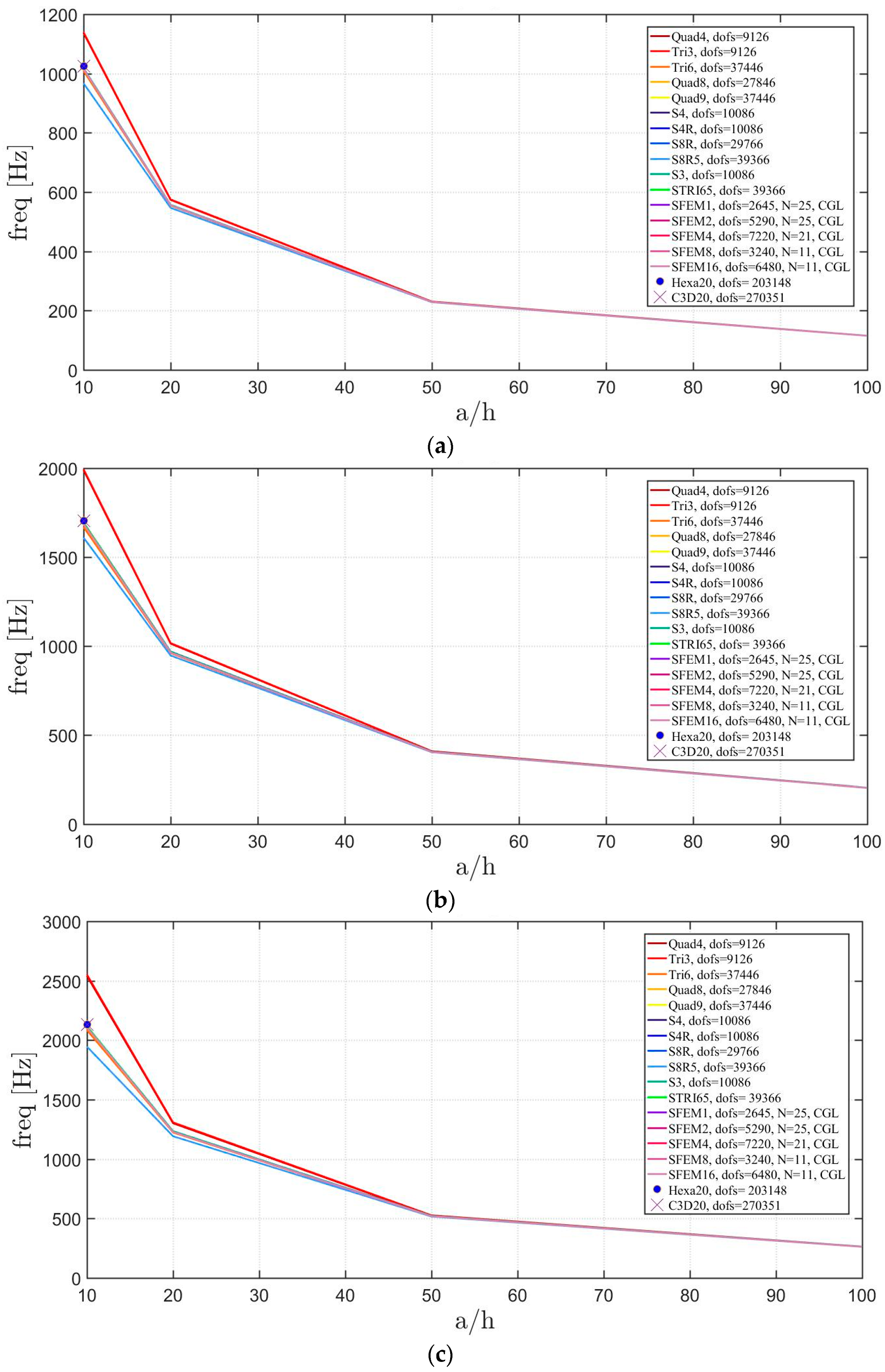
Figure 5.
First three natural frequencies of an isotropic circular plate: (a) First frequency; (b) Second frequency; (c) Third frequency.
Figure 5.
First three natural frequencies of an isotropic circular plate: (a) First frequency; (b) Second frequency; (c) Third frequency.
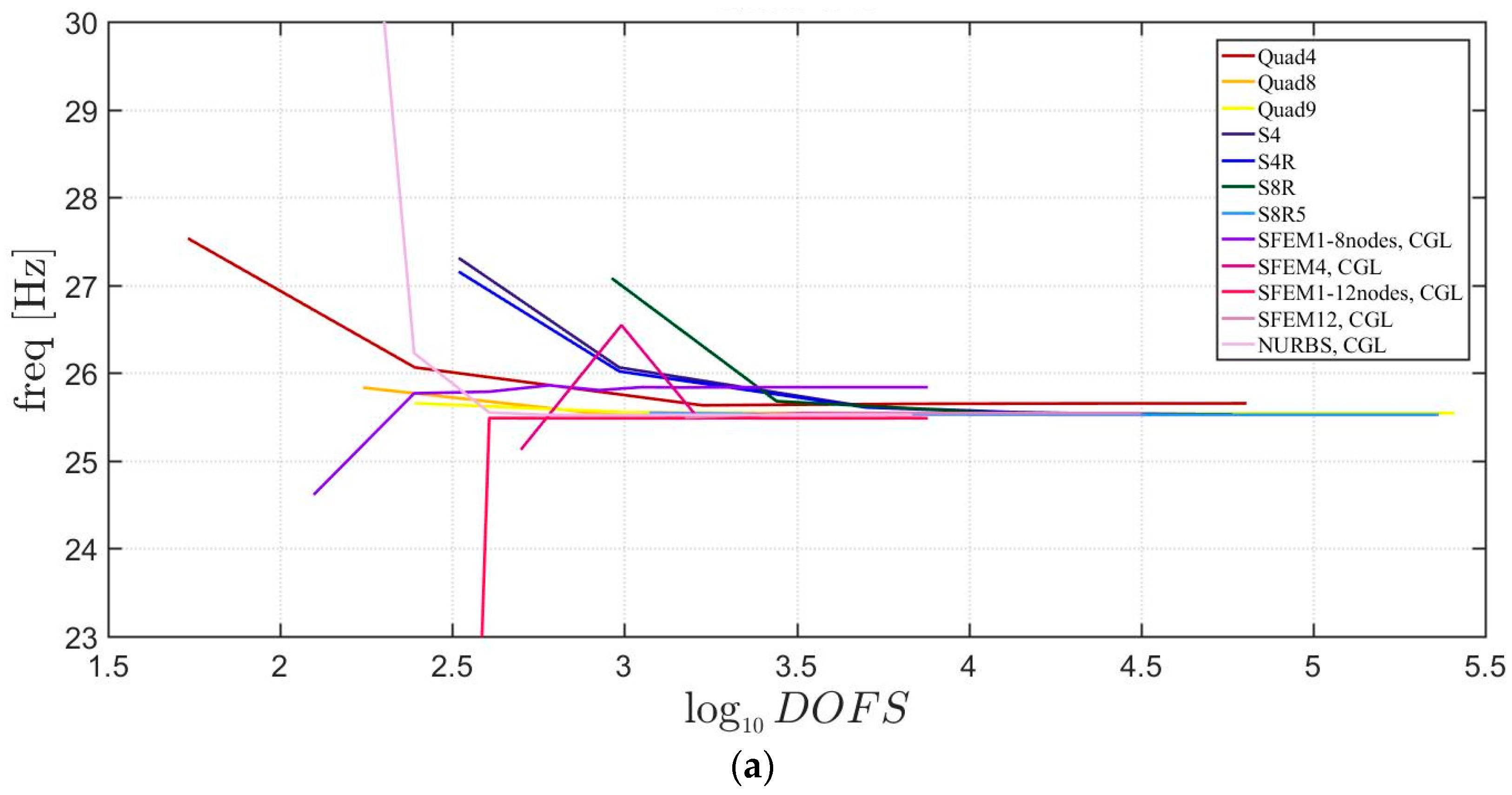

Figure 6.
Thickness effect on the first three natural frequencies of an isotropic circular plate: (a) First frequency; (b) Second frequency; (c) Third frequency.
Figure 6.
Thickness effect on the first three natural frequencies of an isotropic circular plate: (a) First frequency; (b) Second frequency; (c) Third frequency.
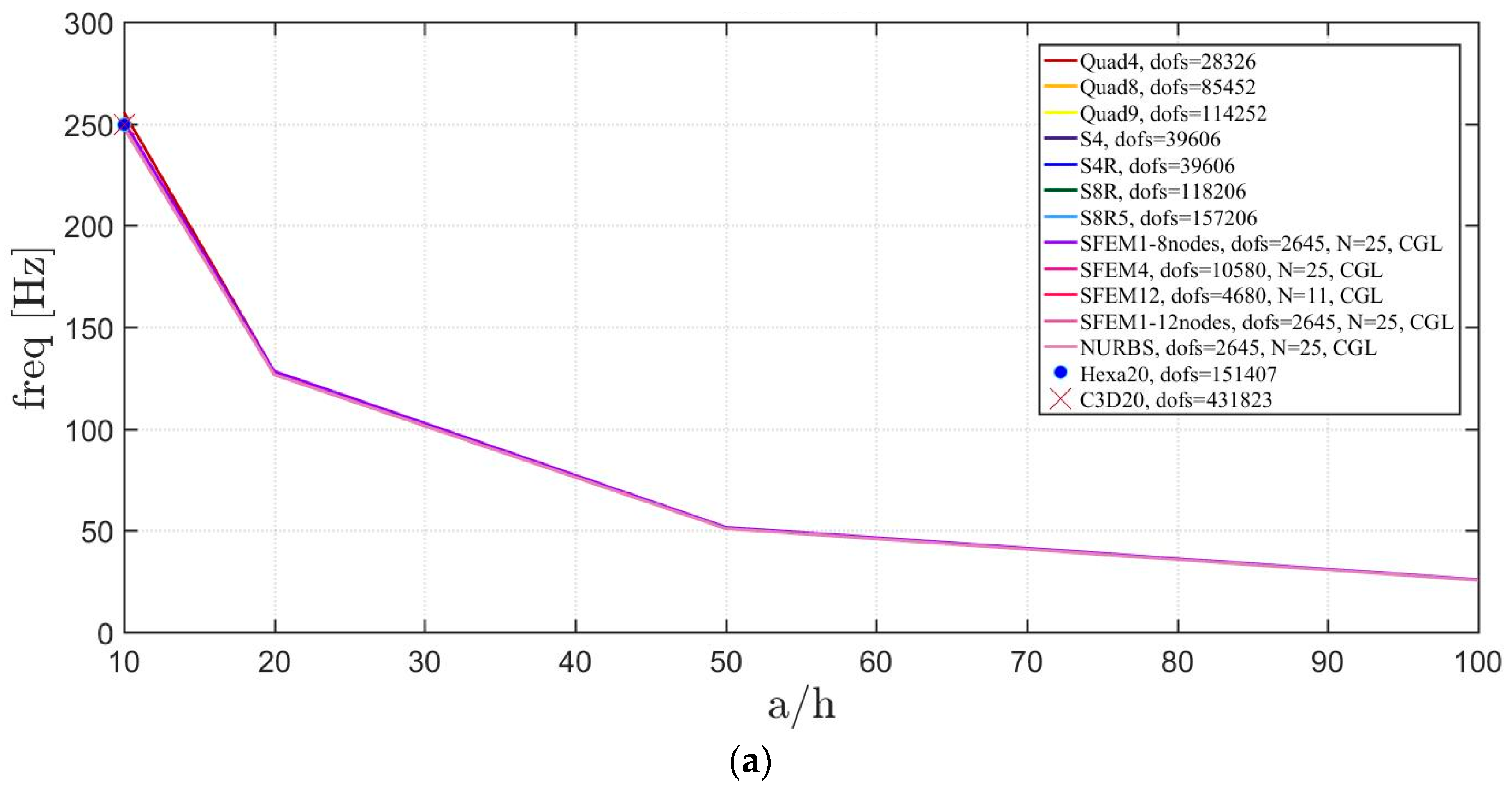

Figure 7.
First three natural frequencies of an isotropic elliptic plate with : (a) First frequency; (b) Second frequency; (c) Third frequency.
Figure 7.
First three natural frequencies of an isotropic elliptic plate with : (a) First frequency; (b) Second frequency; (c) Third frequency.
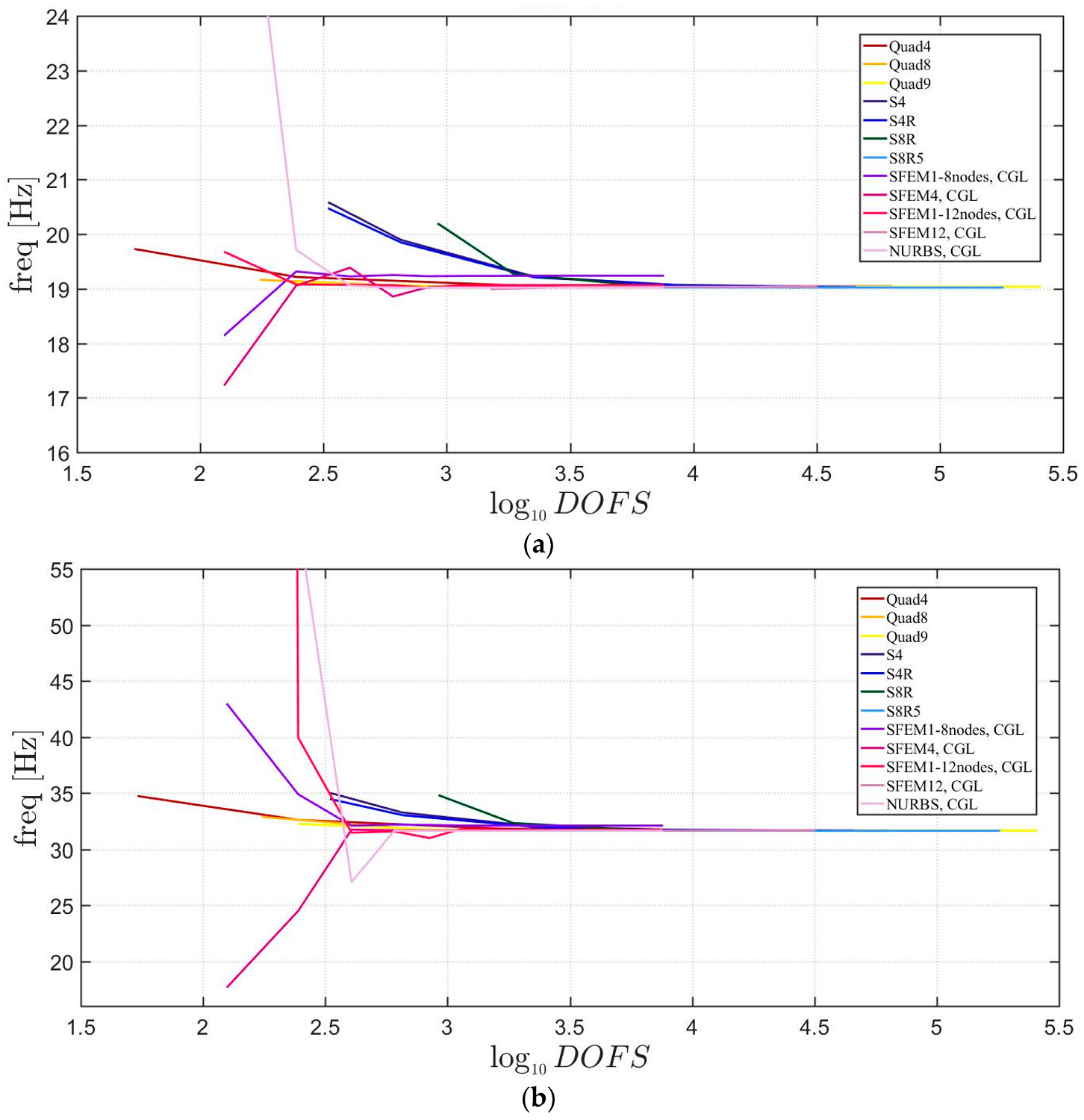

Figure 8.
First three natural frequencies of an isotropic elliptic plate with : (a) First frequency; (b) Second frequency; (c) Third frequency.
Figure 8.
First three natural frequencies of an isotropic elliptic plate with : (a) First frequency; (b) Second frequency; (c) Third frequency.


Figure 9.
First three natural frequencies of an isotropic elliptic plate with : (a) First frequency; (b) Second frequency; (c) Third frequency.
Figure 9.
First three natural frequencies of an isotropic elliptic plate with : (a) First frequency; (b) Second frequency; (c) Third frequency.
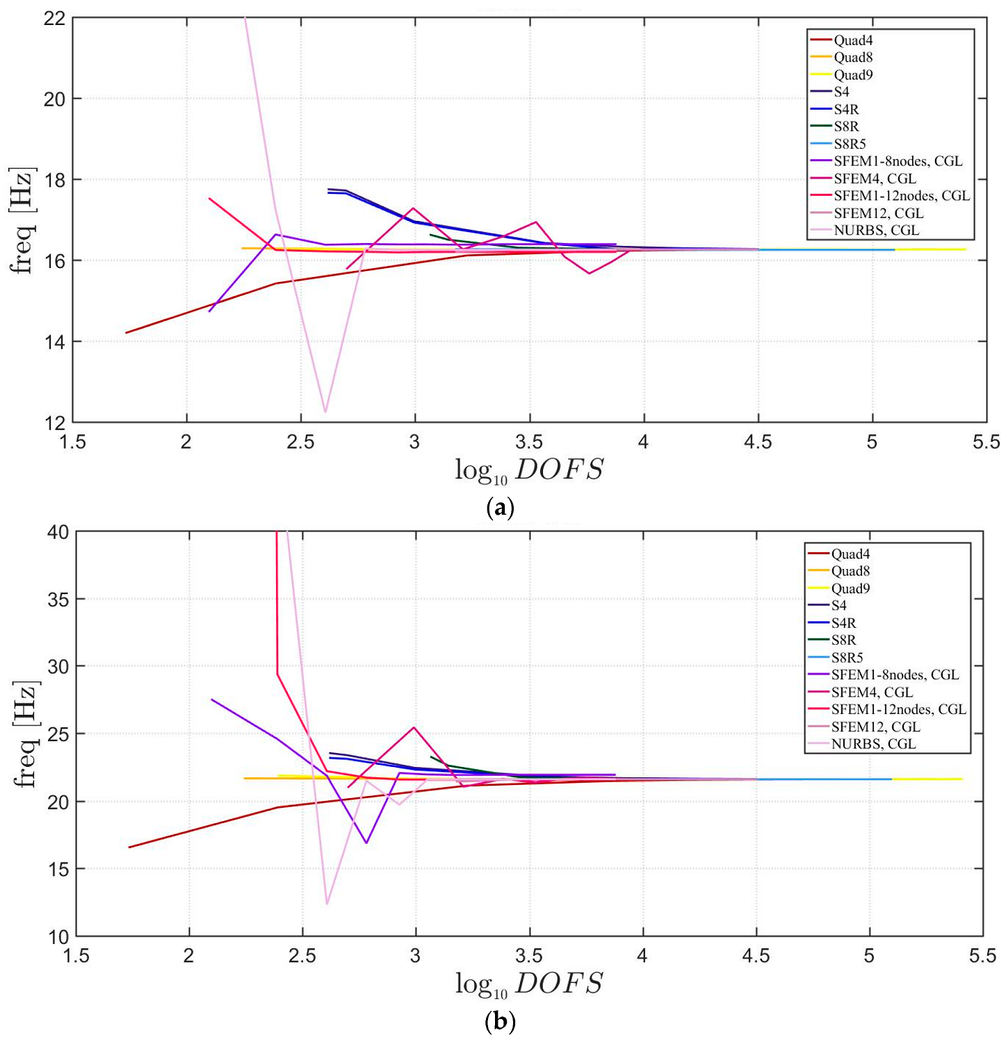

Figure 10.
Thickness effect on the first three natural frequencies of an isotropic elliptic plate with : (a) First frequency; (b) Second frequency; (c) Third frequency.
Figure 10.
Thickness effect on the first three natural frequencies of an isotropic elliptic plate with : (a) First frequency; (b) Second frequency; (c) Third frequency.


Figure 11.
Thickness effect on the first three natural frequencies of an isotropic elliptic plate with : (a) First frequency; (b) Second frequency; (c) Third frequency.
Figure 11.
Thickness effect on the first three natural frequencies of an isotropic elliptic plate with : (a) First frequency; (b) Second frequency; (c) Third frequency.


Figure 12.
Thickness effect on the first three natural frequencies of an isotropic elliptic plate with : (a) First frequency; (b) Second frequency; (c) Third frequency.
Figure 12.
Thickness effect on the first three natural frequencies of an isotropic elliptic plate with : (a) First frequency; (b) Second frequency; (c) Third frequency.
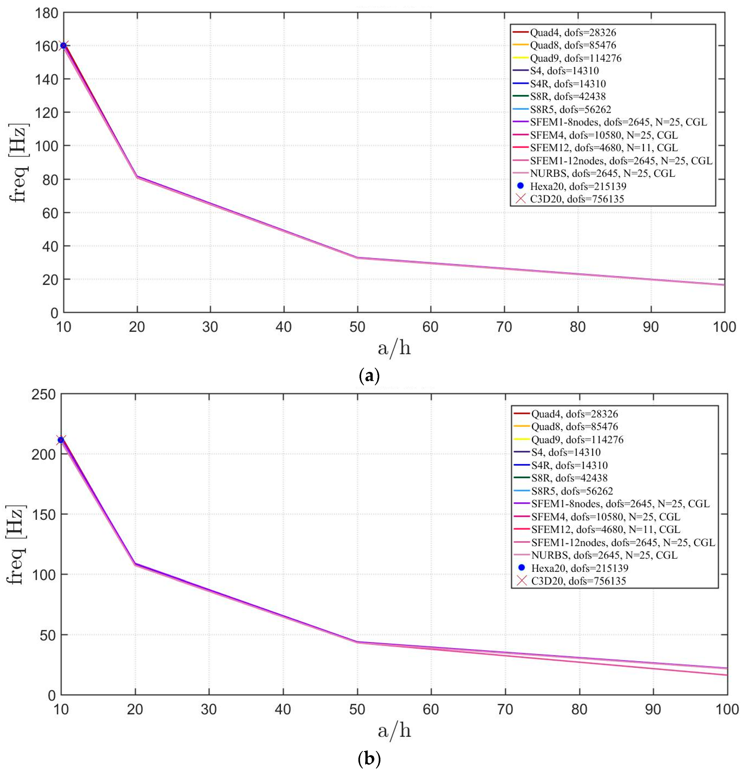

Figure 13.
First three natural frequencies of a skew plate of 30° with a symmetric lamination scheme: (a) First frequency; (b) Second frequency; (c) Third frequency.
Figure 13.
First three natural frequencies of a skew plate of 30° with a symmetric lamination scheme: (a) First frequency; (b) Second frequency; (c) Third frequency.
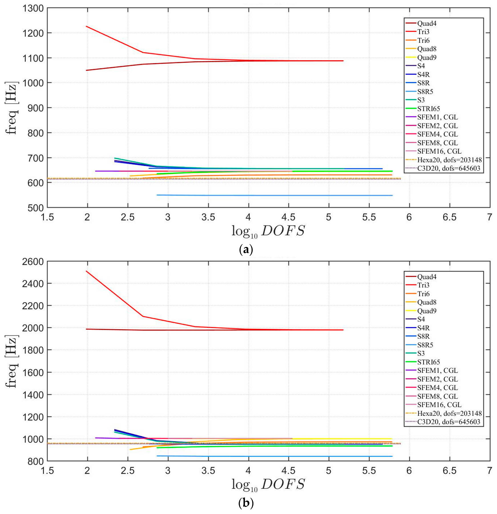
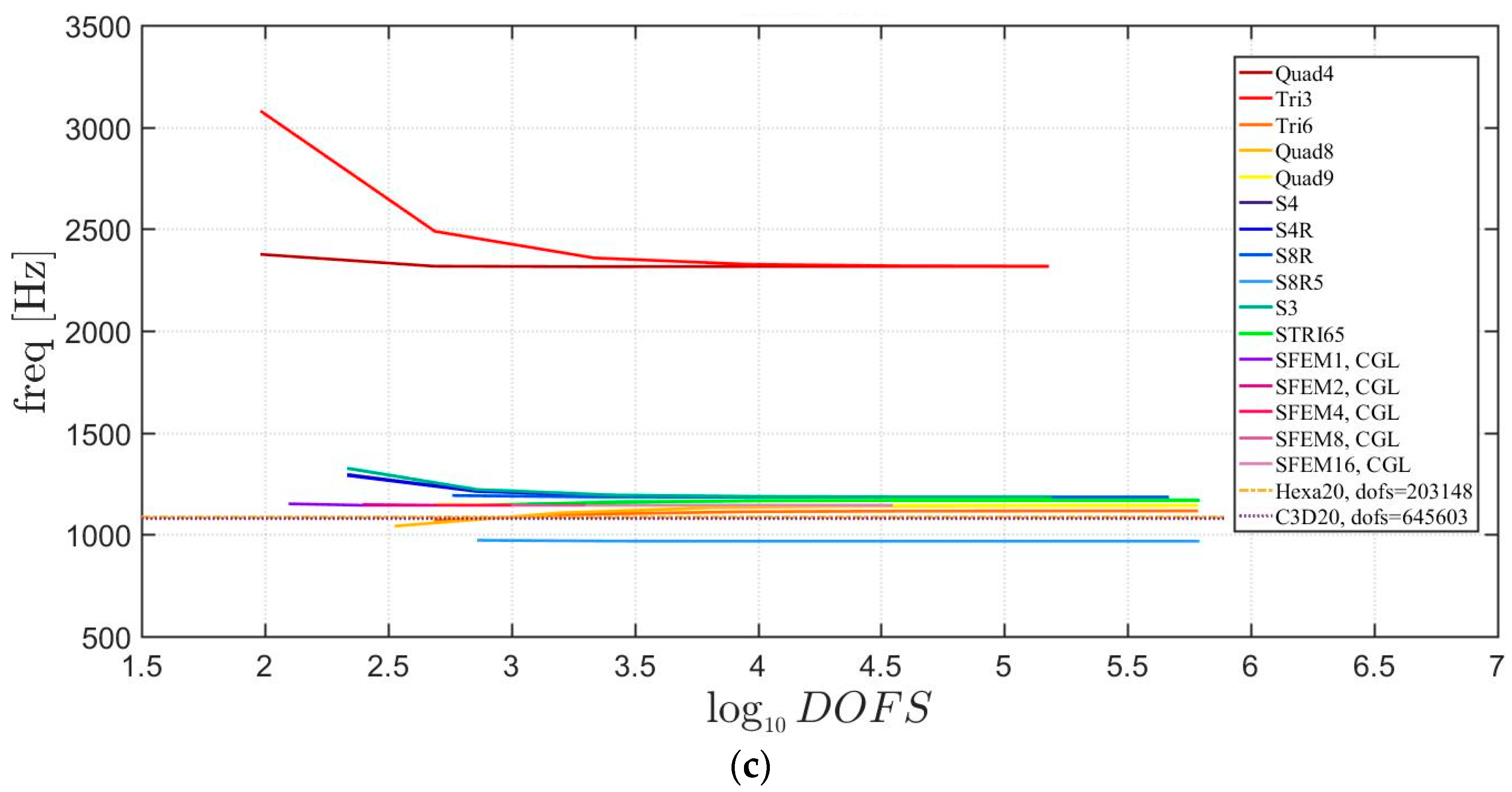
Figure 14.
First three natural frequencies of a skew plate of 30° with a not-symmetric lamination scheme: (a) First frequency; (b) Second frequency; (c) Third frequency.
Figure 14.
First three natural frequencies of a skew plate of 30° with a not-symmetric lamination scheme: (a) First frequency; (b) Second frequency; (c) Third frequency.

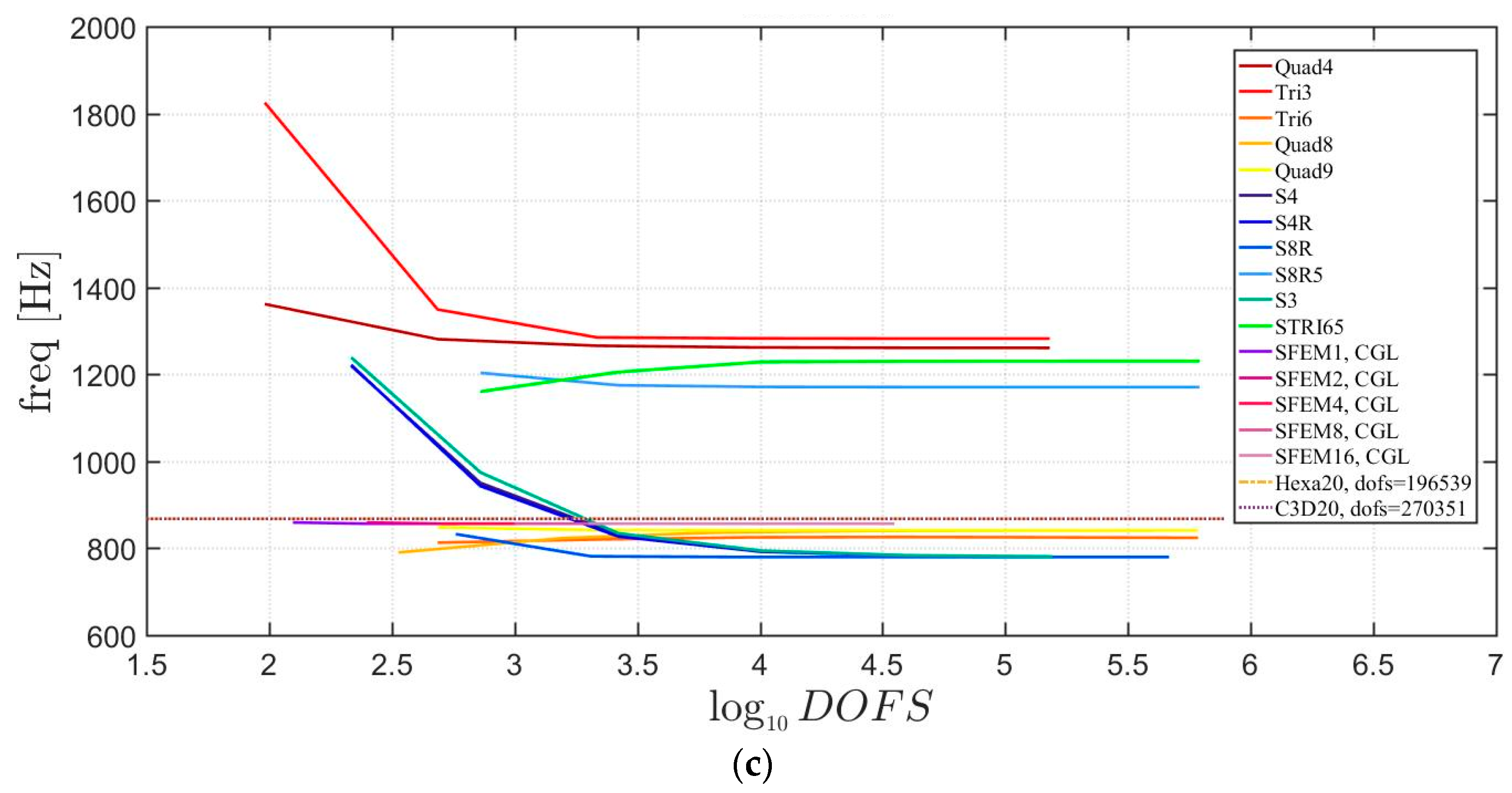
Figure 15.
Thickness effect on the first three natural frequencies of a skew plate with a symmetric lamination scheme: (a) First frequency; (b) Second frequency; (c) Third frequency.
Figure 15.
Thickness effect on the first three natural frequencies of a skew plate with a symmetric lamination scheme: (a) First frequency; (b) Second frequency; (c) Third frequency.

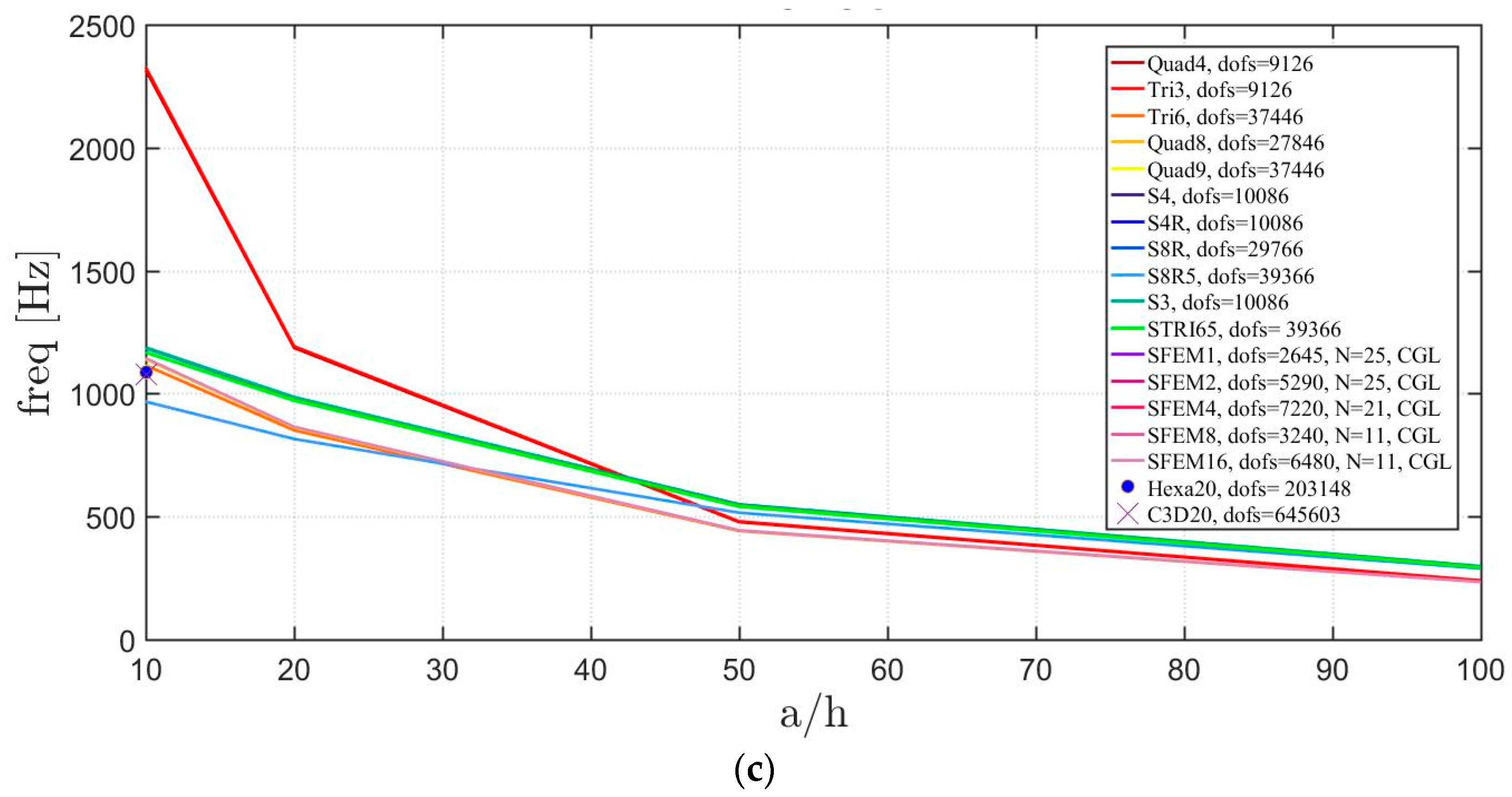
Figure 16.
Thickness effect on the first three natural frequencies of a skew plate with a not-symmetric lamination scheme: (a) First frequency; (b) Second frequency; (c) Third frequency.
Figure 16.
Thickness effect on the first three natural frequencies of a skew plate with a not-symmetric lamination scheme: (a) First frequency; (b) Second frequency; (c) Third frequency.


Figure 17.
First three natural frequencies of a circular plate with a symmetric lamination scheme and : (a) First frequency; (b) Second frequency; (c) Third frequency.
Figure 17.
First three natural frequencies of a circular plate with a symmetric lamination scheme and : (a) First frequency; (b) Second frequency; (c) Third frequency.
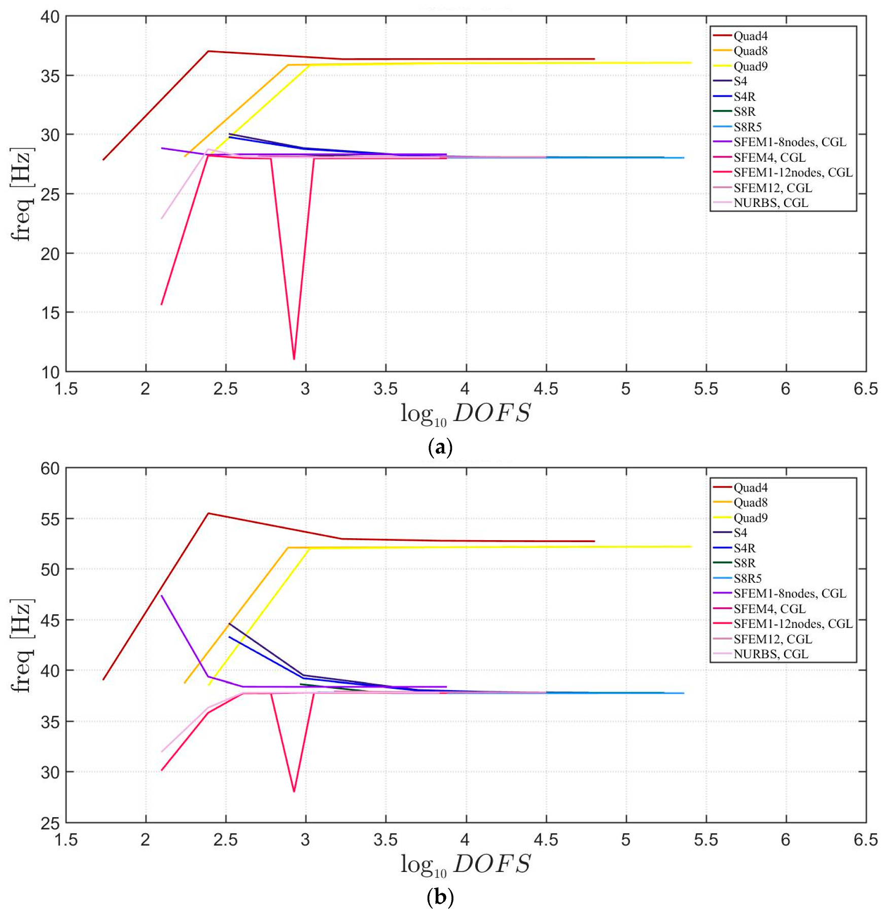

Figure 18.
First three natural frequencies of a circular plate with a symmetric lamination scheme and : (a) First frequency; (b) Second frequency; (c) Third frequency.
Figure 18.
First three natural frequencies of a circular plate with a symmetric lamination scheme and : (a) First frequency; (b) Second frequency; (c) Third frequency.
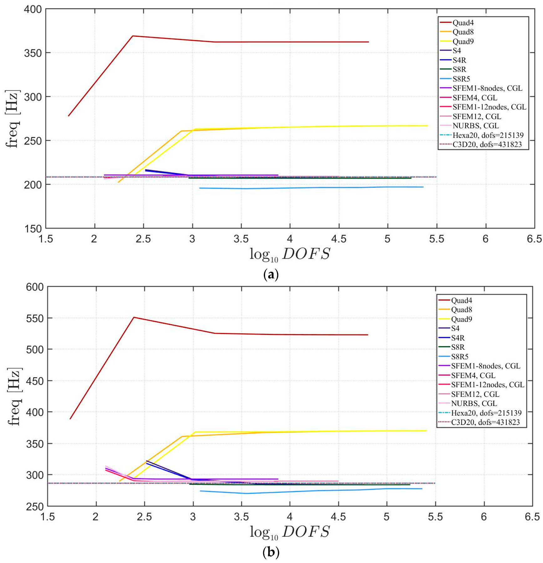

Figure 19.
Thickness effect on the first three natural frequencies of a circular plate with a symmetric lamination scheme: (a) First frequency; (b) Second frequency; (c) Third frequency.
Figure 19.
Thickness effect on the first three natural frequencies of a circular plate with a symmetric lamination scheme: (a) First frequency; (b) Second frequency; (c) Third frequency.


Figure 20.
First three natural frequencies of a circular plate with a not-symmetric lamination scheme and a/h = 100: (a) First frequency; (b) Second frequency; (c) Third frequency.
Figure 20.
First three natural frequencies of a circular plate with a not-symmetric lamination scheme and a/h = 100: (a) First frequency; (b) Second frequency; (c) Third frequency.
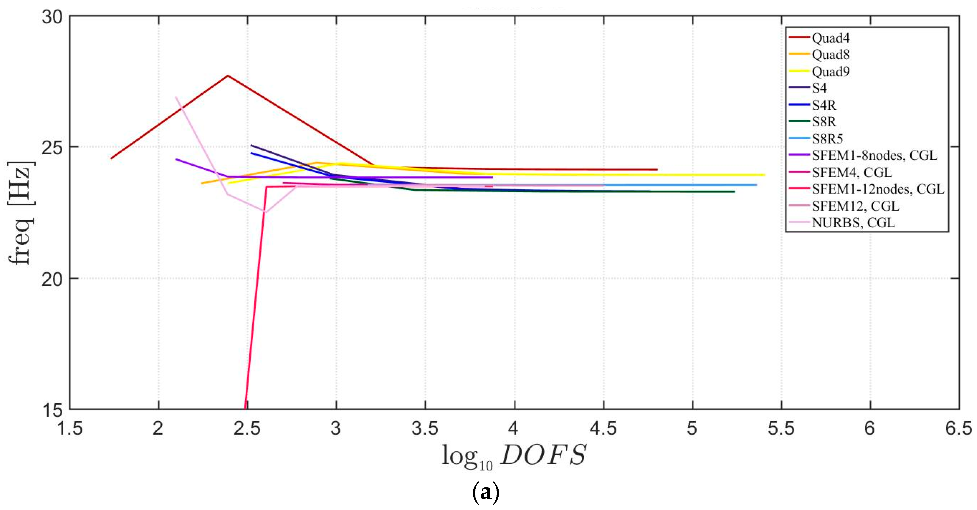
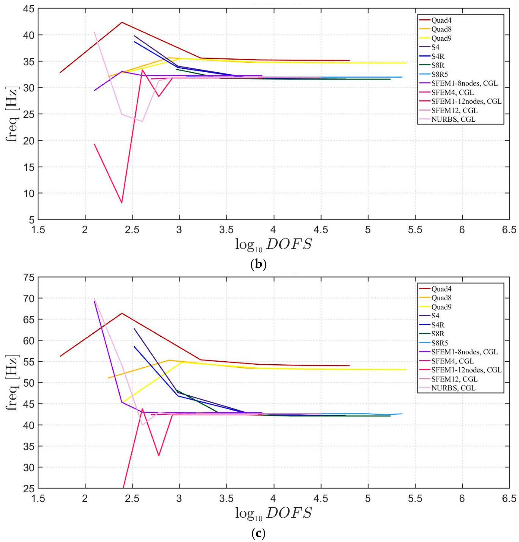
Figure 21.
First three natural frequencies of a circular plate with a not-symmetric lamination scheme and a/h = 10: (a) First frequency; (b) Second frequency; (c) Third frequency.
Figure 21.
First three natural frequencies of a circular plate with a not-symmetric lamination scheme and a/h = 10: (a) First frequency; (b) Second frequency; (c) Third frequency.
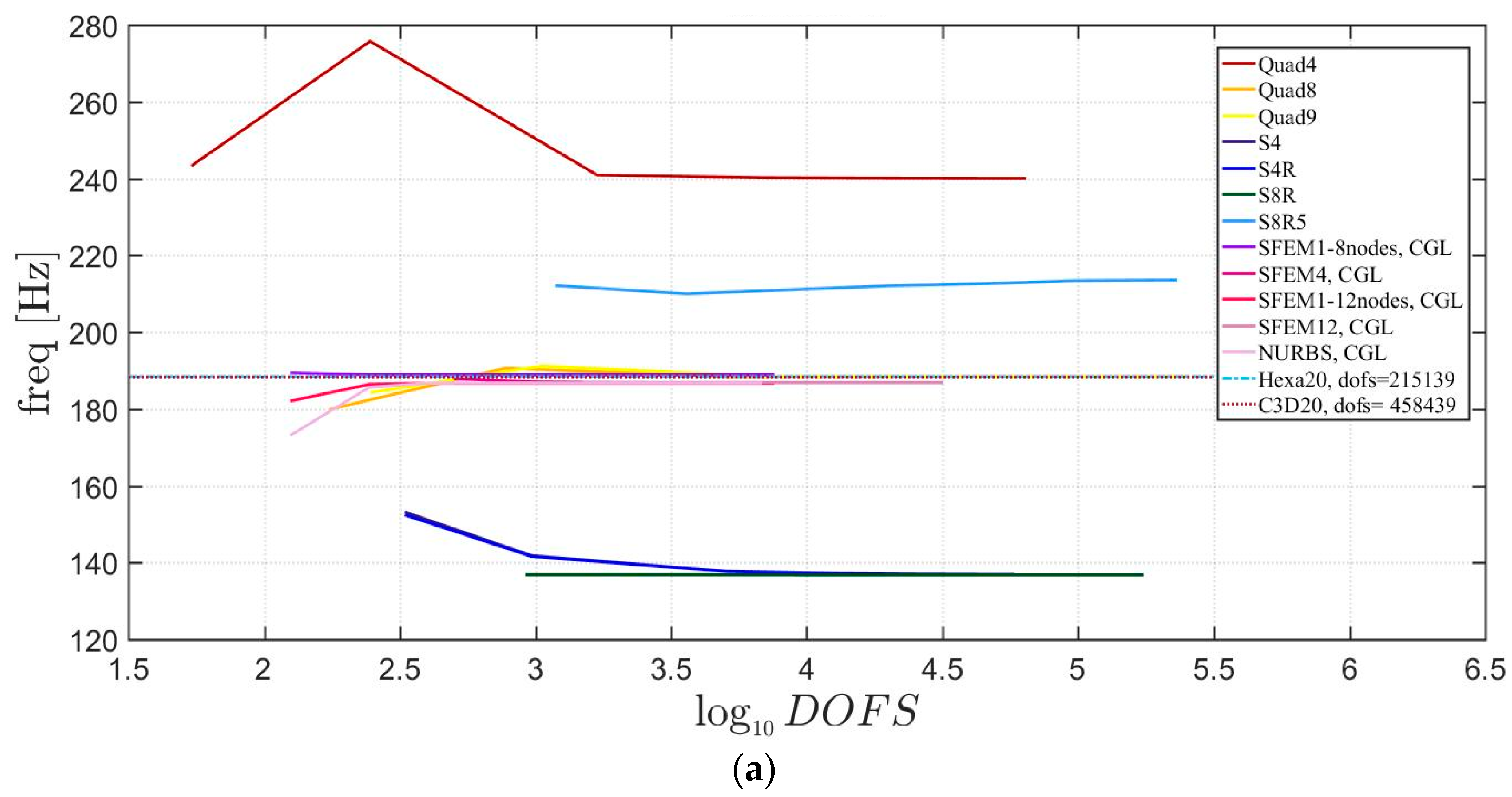

Figure 22.
Thickness effect on the first three natural frequencies of a circular plate with a not-symmetric lamination scheme: (a) First frequency; (b) Second frequency; (c) Third frequency.
Figure 22.
Thickness effect on the first three natural frequencies of a circular plate with a not-symmetric lamination scheme: (a) First frequency; (b) Second frequency; (c) Third frequency.


Figure 23.
First three natural frequencies of an elliptic plate with a/b = 1.5 a symmetric lamination scheme and a/h = 10: (a) First frequency; (b) Second frequency; (c) Third frequency.
Figure 23.
First three natural frequencies of an elliptic plate with a/b = 1.5 a symmetric lamination scheme and a/h = 10: (a) First frequency; (b) Second frequency; (c) Third frequency.
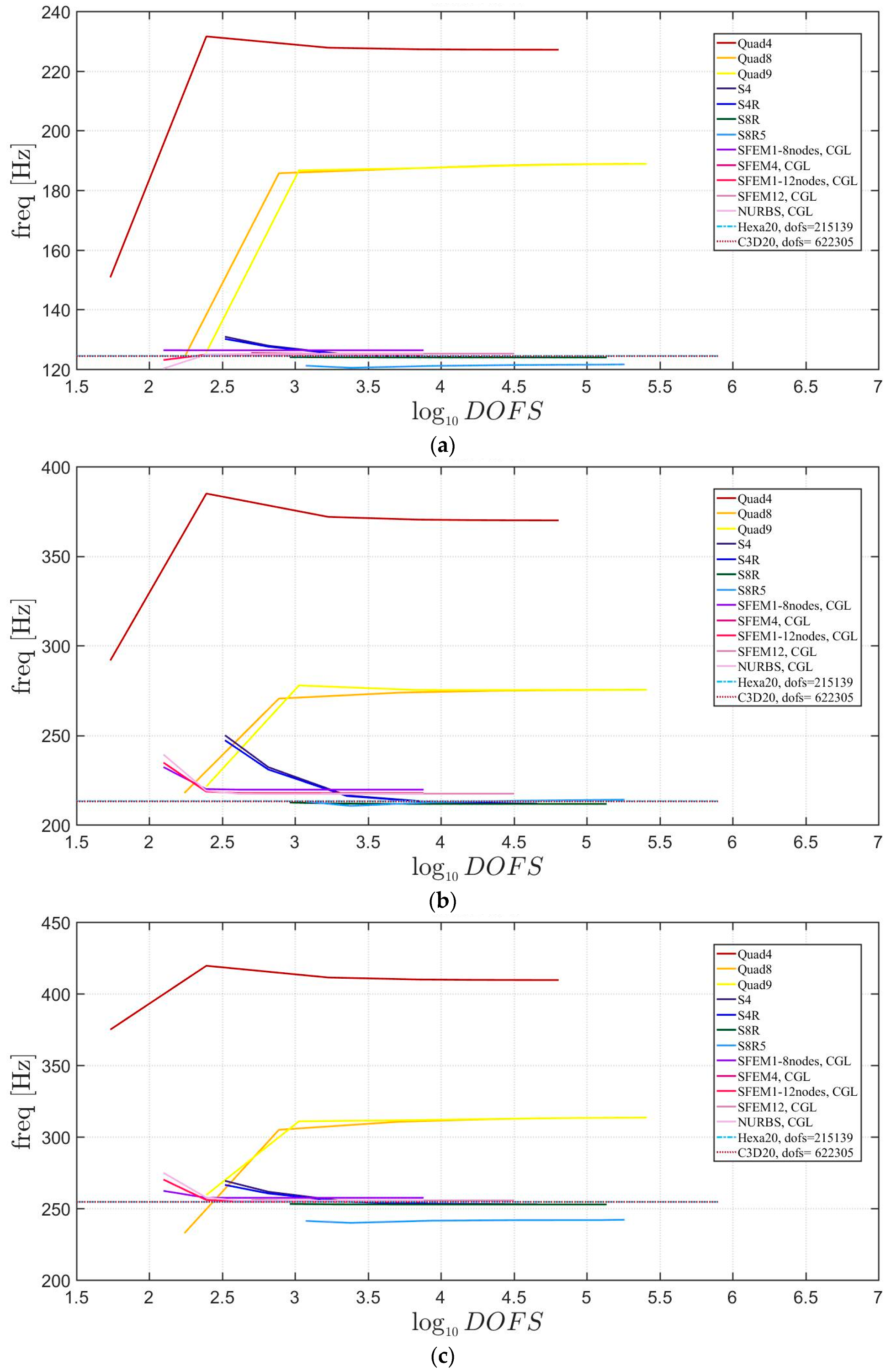
Figure 24.
First three natural frequencies of an elliptic plate with a/b = 2 a symmetric lamination scheme and a/h = 10: (a) First frequency; (b) Second frequency; (c) Third frequency.
Figure 24.
First three natural frequencies of an elliptic plate with a/b = 2 a symmetric lamination scheme and a/h = 10: (a) First frequency; (b) Second frequency; (c) Third frequency.

Figure 25.
First three natural frequencies of an elliptic plate with a/b = 2.5 a symmetric lamination scheme and a/h = 10: (a) First frequency; (b) Second frequency; (c) Third frequency.
Figure 25.
First three natural frequencies of an elliptic plate with a/b = 2.5 a symmetric lamination scheme and a/h = 10: (a) First frequency; (b) Second frequency; (c) Third frequency.

Figure 26.
Thickness effect on the first three natural frequencies of an elliptic plate a/b = 1.5 with a symmetric lamination scheme: (a) First frequency; (b) Second frequency; (c) Third frequency.
Figure 26.
Thickness effect on the first three natural frequencies of an elliptic plate a/b = 1.5 with a symmetric lamination scheme: (a) First frequency; (b) Second frequency; (c) Third frequency.
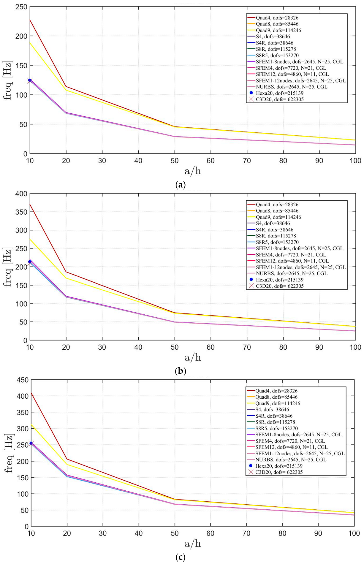
Figure 27.
Thickness effect on the first three natural frequencies of an elliptic plate a/b = 2 with a symmetric lamination scheme: (a) First frequency; (b) Second frequency; (c) Third frequency.
Figure 27.
Thickness effect on the first three natural frequencies of an elliptic plate a/b = 2 with a symmetric lamination scheme: (a) First frequency; (b) Second frequency; (c) Third frequency.

Figure 28.
Thickness effect on the first three natural frequencies of an elliptic plate a/b = 2.5 with a symmetric lamination scheme: (a) First frequency; (b) Second frequency; (c) Third frequency.
Figure 28.
Thickness effect on the first three natural frequencies of an elliptic plate a/b = 2.5 with a symmetric lamination scheme: (a) First frequency; (b) Second frequency; (c) Third frequency.

Figure 29.
First three natural frequencies of an elliptic plate with a/b = 1.5 a not-symmetric lamination scheme and a/h = 10: (a) First frequency; (b) Second frequency; (c) Third frequency.
Figure 29.
First three natural frequencies of an elliptic plate with a/b = 1.5 a not-symmetric lamination scheme and a/h = 10: (a) First frequency; (b) Second frequency; (c) Third frequency.
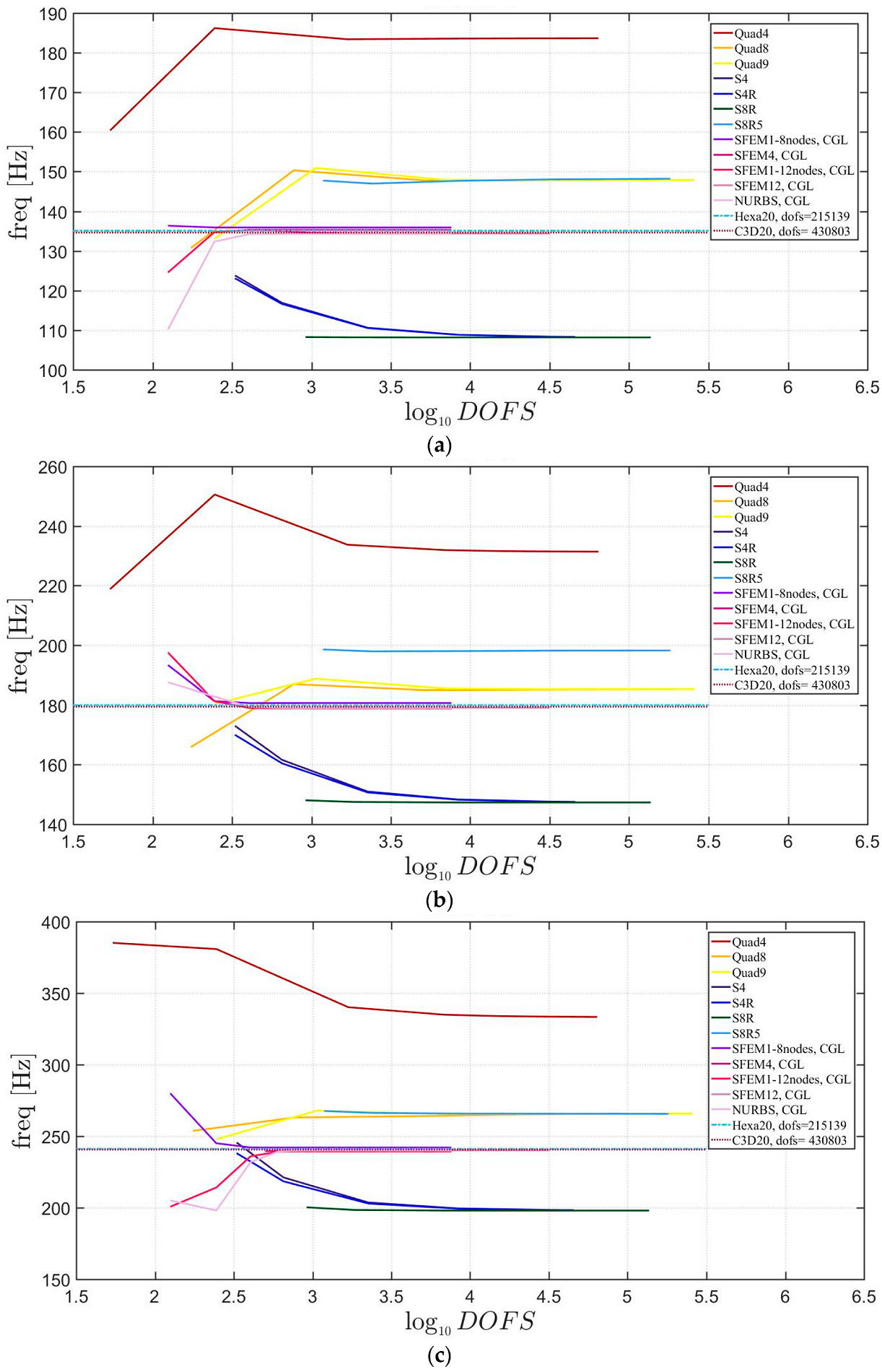
Figure 30.
First three natural frequencies of an elliptic plate with a/b = 2 a not-symmetric lamination scheme and a/h = 10: (a) First frequency; (b) Second frequency; (c) Third frequency.
Figure 30.
First three natural frequencies of an elliptic plate with a/b = 2 a not-symmetric lamination scheme and a/h = 10: (a) First frequency; (b) Second frequency; (c) Third frequency.
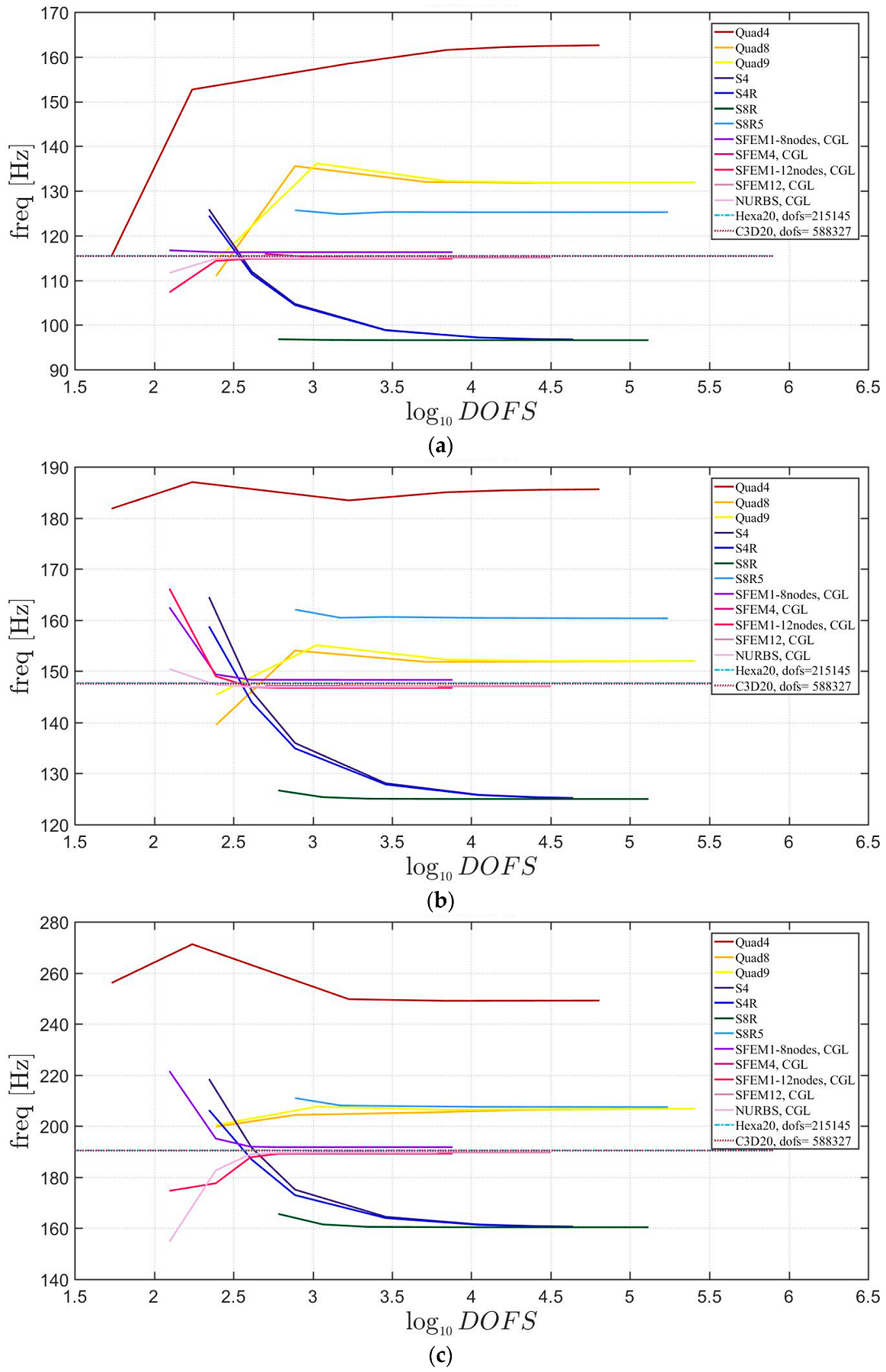
Figure 31.
First three natural frequencies of an elliptic plate with a/b = 2.5 a not-symmetric lamination scheme and a/h = 10: (a) First frequency; (b) Second frequency; (c) Third frequency.
Figure 31.
First three natural frequencies of an elliptic plate with a/b = 2.5 a not-symmetric lamination scheme and a/h = 10: (a) First frequency; (b) Second frequency; (c) Third frequency.

Figure 32.
Thickness effect on the first three natural frequencies of an elliptic plate a/b = 1.5 with a not-symmetric lamination scheme: (a) First frequency; (b) Second frequency; (c) Third frequency.
Figure 32.
Thickness effect on the first three natural frequencies of an elliptic plate a/b = 1.5 with a not-symmetric lamination scheme: (a) First frequency; (b) Second frequency; (c) Third frequency.

Figure 33.
Thickness effect on the first three natural frequencies of an elliptic plate a/b = 2 with a not-symmetric lamination scheme: (a) First frequency; (b) Second frequency; (c) Third frequency.
Figure 33.
Thickness effect on the first three natural frequencies of an elliptic plate a/b = 2 with a not-symmetric lamination scheme: (a) First frequency; (b) Second frequency; (c) Third frequency.

Figure 34.
Thickness effect on the first three natural frequencies of an elliptic plate a/b = 2.5 with a not-symmetric lamination scheme: (a) First frequency; (b) Second frequency; (c) Third frequency.
Figure 34.
Thickness effect on the first three natural frequencies of an elliptic plate a/b = 2.5 with a not-symmetric lamination scheme: (a) First frequency; (b) Second frequency; (c) Third frequency.

© 2018 by the authors. Licensee MDPI, Basel, Switzerland. This article is an open access article distributed under the terms and conditions of the Creative Commons Attribution (CC BY) license (http://creativecommons.org/licenses/by/4.0/).
Share and Cite
MDPI and ACS Style
Fantuzzi, N.; Tornabene, F.; Bacciocchi, M.; Ferreira, A.J.M. On the Convergence of Laminated Composite Plates of Arbitrary Shape through Finite Element Models. J. Compos. Sci. 2018, 2, 16. https://doi.org/10.3390/jcs2010016
AMA Style
Fantuzzi N, Tornabene F, Bacciocchi M, Ferreira AJM. On the Convergence of Laminated Composite Plates of Arbitrary Shape through Finite Element Models. Journal of Composites Science. 2018; 2(1):16. https://doi.org/10.3390/jcs2010016
Chicago/Turabian StyleFantuzzi, Nicholas, Francesco Tornabene, Michele Bacciocchi, and Antonio J.M. Ferreira. 2018. "On the Convergence of Laminated Composite Plates of Arbitrary Shape through Finite Element Models" Journal of Composites Science 2, no. 1: 16. https://doi.org/10.3390/jcs2010016