Design and Construction of CFRP Rod Panel Retrofit for Impacted RC Bridge Girders

1
Kentucky Transportation Center, University of Kentucky, Lexington, KY 40506, USA
2
Department of Civil Engineering, University of Kentucky, Lexington, KY 40506, USA
*
Author to whom correspondence should be addressed.
J. Compos. Sci. 2018, 2(3), 40; https://doi.org/10.3390/jcs2030040
Submission received: 30 May 2018
/
Revised: 29 June 2018
/
Accepted: 10 July 2018
/
Published: 11 July 2018
(This article belongs to the Special Issue Use of Fiber-Reinforced Polymer Composites in Civil Engineering)
Abstract
:CFRP Rod Panels (CRPs) have been recently developed to externally strengthening concrete structures in flexure, especially over multi-lane highways. Both exterior beams of a reinforced concrete (RC) bridge traversing southbound Interstate 71 (I-71) in Kentucky were damaged by an over-height truck impact. Rebars within the bottom mat of each exterior beam were severely bent due to the impact. CRP 195, with CFRP rods 3.96-mm (0.156 in) in diameter, and having a capacity of 870 kN (195.6 kips) per 300 mm (12 in) width of panel, were selected for flexural strengthening. CRPs were chosen due to their modular construction capability permitting a smaller work crew to carry out the retrofit construction while requiring closure of only a single lane of traffic on I-71. As current codes do not address CRPs, the retrofit design was based on American Association of State Highway and Transportation Officials (AASHTO) guidelines for externally bonded FRP. A load rating of the impacted girders was carried out for the as-built, damaged, and retrofitted stages. This paper details the retrofit construction of the bridge girders, highlighting the advantages of the CRPs.
1. Introduction
Bridge superstructures in the United States (US) and throughout the world are routinely damaged by over-height truck impacts. Bridges impacted by over-height trucks may require a load posting if the impact causes moderate to severe damage. Bridge closure may ensue, following some severe impacts due to structural failure or loss of structural integrity, which can lead to imminent failure. While impacts to steel beams and built-up steel girders are comparatively fixable by heat-straightening, welding, or bolting of replacement components, correcting damage to both reinforced concrete (RC) and prestressed concrete (PC) beams presents more complex challenges. Damage caused by over-height truck impacts to RC and PC bridge beams include cracking of beams, damage to reinforcement and/or prestressing strands, yielding of steel, spalling of concrete, and failure of joints and connections, among other types. Several studies have addressed the reparation of impact damages in different types of bridges. National Cooperative Highway Research Program (NCHRP) Report 271 [1] discusses the evaluation and repair of damaged steel girders. NCHRP Report 226 [2], Report 280 [3], and the recent NCHRP 20-07/Task 307 [4] provide guidelines on the inspection and repair of PC bridge beams. While numerous laboratory and field applications of strengthening RC beams are available, there are no guidelines or research publications known to the authors which specifically address the impact damage repair of RC bridge girders.
Following an over-height truck impact to a bridge, most state departments of transportation (DOTs) in the US evaluate damage and decide whether a load posting is necessary. Unless it is extremely unsafe and requires immediate attention, impact damages may only be fixed several months or years after the actual impact, when funds are available. Most impacted locations have low clearances and often endure multiple impacts. Delaying repairs or not addressing the damage immediately can result in subsequent impacts going undetected, and the damage unevaluated. This presents a safety issue to the travelling public. The corrosion of exposed rebar or prestressing strands worsens over time, leading to section loss and loss in member capacity. Following several over-height bridge repair projects on both RC and PC bridges in the state of Kentucky, the authors developed a two-stage approach to the containment and/or eventual repair of a damaged area [5]. The first approach outlined the immediate action needed following an impact to prevent loose concrete blocks from falling on the traveling public, while the second approach encompasses a methodology for repairing the impacted area and providing containment in the event of future impacts.
The traditional methods of repairing both RC and PC bridge girders with damaged or severed reinforcing bars are internal mechanical coupling/splicing and external steel jackets/sleeves [2,3,6,7]. Depending on the size and number of rebars damaged at the point of impact, mechanical splicing may not be viable for RC girders if space for their application is limited. Steel jackets require field welding, are labor intensive to install, and are prone to corrosion over time. Over the last 20 years, Fiber Reinforced Polymer (FRP) laminates and fabrics have become popular choices for repairing and strengthening concrete girders. In addition to their noncorrosive properties, magnetic transparency, durability, and ease of application, Carbon Fiber Reinforced Polymer (CFRP) composites are very cost-efficient compared to other FRP materials, given their high strength-to-weight ratio. Multiple organizations have developed guidelines on the use of FRP, including the American Concrete Institute (ACI) [8], American Association of State Highway and Transportation Officials (AASHTO) [9], Japan Society of Civil Engineers (JSCE) [10], and International Federation for Structural Concrete (fib) [11]. Field applications of externally bonded CFRP (EB-CFRP), pultruded laminates, and wet-layup sheets/fabric for strengthening RC bridge girders have been documented with excellent results [12,13]. EB-CFRP has been also used successfully to repair and strengthen PC bridges with impact damage [14,15,16,17,18,19]. Full scale laboratory testing of RC bridge beams strengthened with CFRP have been documented [20], while decommissioned PC bridge beams with impact damage have been repaired using EB-CFRP [21,22]. Prestressed CFRP sheets have also been utilized in the retrofit of PC bridges [23,24]. Experimental research has also focused on the use of prestressed Near Surface Mounted (NSM) CFRP bars for strengthening impact damaged PC girders [25]. NCHRP 20-07/Task 307 [4] highlights methods utilizing CFRP for PC bridge retrofit. Many of the findings for PC bridge girders can be extended to RC bridge girders as well.
Due to vertical clearance limits with roadway grade, most over-height impacts tend to be on the exterior girders of bridges. As the impacts are over the roadways below, they also tend to be close to the maximum positive moment regions of those girders. While the impact may occur over a single traffic lane, the damage due to the impact, which includes cracking and spalling of concrete, may span multiple lanes of traffic. Although concrete repair work can be carried out in segments, a retrofit using traditional CFRP laminates may require the closure of multiple traffic lanes to maintain continuity of the laminate over the entire retrofit area. CFRP laminates can be spliced; however, splice places can debond, especially when the splice is close to the maximum moment region [26]. The authors developed CFRP Rod Panels (CRPs) as a method of eliminating the need for splice plates by utilizing a modular retrofit construction [27,28]. The paper details the damage caused by an over-height truck impact to an overpass over Interstate 71 (I-71) in Kentucky and the design and retrofit of the impacted RC girders using CRPs.
2. CFRP Rod Panels
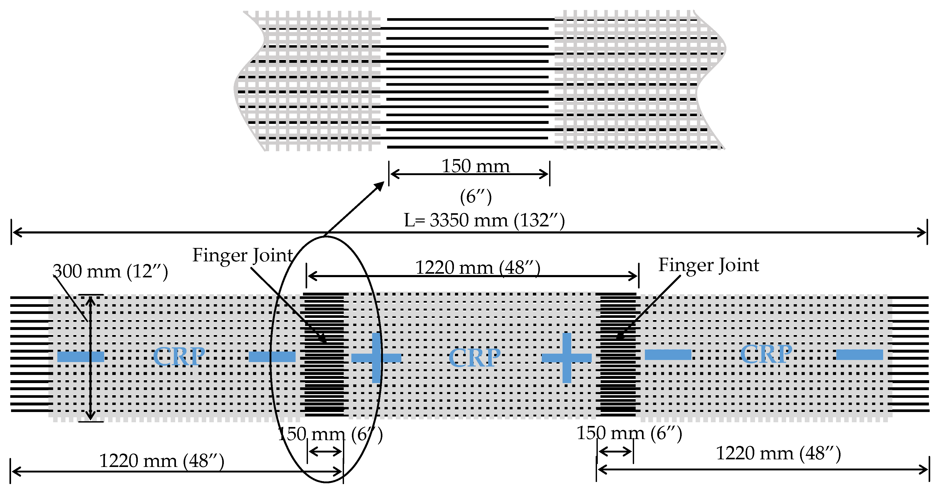
CRPs are produced using small-diameter CFRP rods, which are mounted on a fiberglass backing. The backing maintains spacing between rods greater than the diameter of individual rods (Figure 1). Several CFRP rods, with diameters varying from 1.98 mm (0.078 in) to 3.96 mm (0.156 in), have been experimentally evaluated by the authors [27,29]. The CFRP used in the rods has a manufacturer-reported tensile modulus of 134 GPa (19,500 ksi) and an ultimate tensile strength of 2200 MPa (320 ksi). The individual rod area and spacing, along with the material properties for the two CFRP rod diameters that the authors have experimentally assessed and deployed in the field, are provided in Table 1. The panels are 1220 mm (48 in) in length, but can be designed to be of any length. The selected length allows individual workers to easily handle and mount the panels on the soffit of a girder. The system’s modular construction is made possible through the use of a finger joint between adjacent panels. Alternating panels are produced with an extra rod to establish symmetry at the finger joint. The 150 mm (6 in) overlap for the finger joint was a conservative selection based on the results of double lap shear tests [27,29]. Rod spacing was calculated to maintain a minimum clear distance between rods at the finger joint. The same two-part structural epoxies used to bond CFRP laminates to a concrete surface are utilized for the CRP application. Laboratory tests on CRP-strengthened concrete beams revealed that the primary mode of failure of the strengthening system is concrete cover delamination [27,30]. Laboratory tests on RC beams strengthened in flexure using both CRP and CFRP laminates, and having approximately the same axial stiffness ([AE]CRP = [AE]Laminate), showed that the CRP strengthened beams had an increase in load carry capacity of 38% over the CFRP laminate strengthened beam [30].
Since 2011, the authors have carried out seven impact damage retrofit projects involving over-height trucks in Kentucky. Three of the projects involved PC bridge girders, while the remaining four were RC girders. Five of the seven bridge girder retrofit projects utilized CRPs. They were chosen as they could be easily applied by a single worker accessing the underside of the impacted girder utilizing a man lift, bucket truck, or similar equipment. The CRPs are applied in a modular fashion one panel after another. The panels are joined together using the finger joint at the panel ends (Figure 1) in order to provide continuity in load carrying capacity over the length of the retrofitted region. The finger joint permits the stoppage of retrofit construction after the application of any panel, provided that the connecting finger joint of the last panel is left void of epoxy. While the labor and equipment savings that accrue from the use of CRP compared to traditional CFRP laminates is clear, its greatest advantage is minimizing traffic disruptions due to lane closures. All the over-height impact-damaged bridges retrofitted by the authors were overpasses located over interstate highways or state parkways in Kentucky. The roadways involved in the above projects had two, three, or four lanes of traffic in a given direction of the interstate/parkway. Particularly in the case where there are only two lanes of traffic and the impact damage spans both lanes, CRPs provide the option for closing just a single lane during the retrofit process. Strengthening over one lane can be carried out and then traffic switched to the opposing lane to execute strengthening over it.
3. Bridge and Damage Details
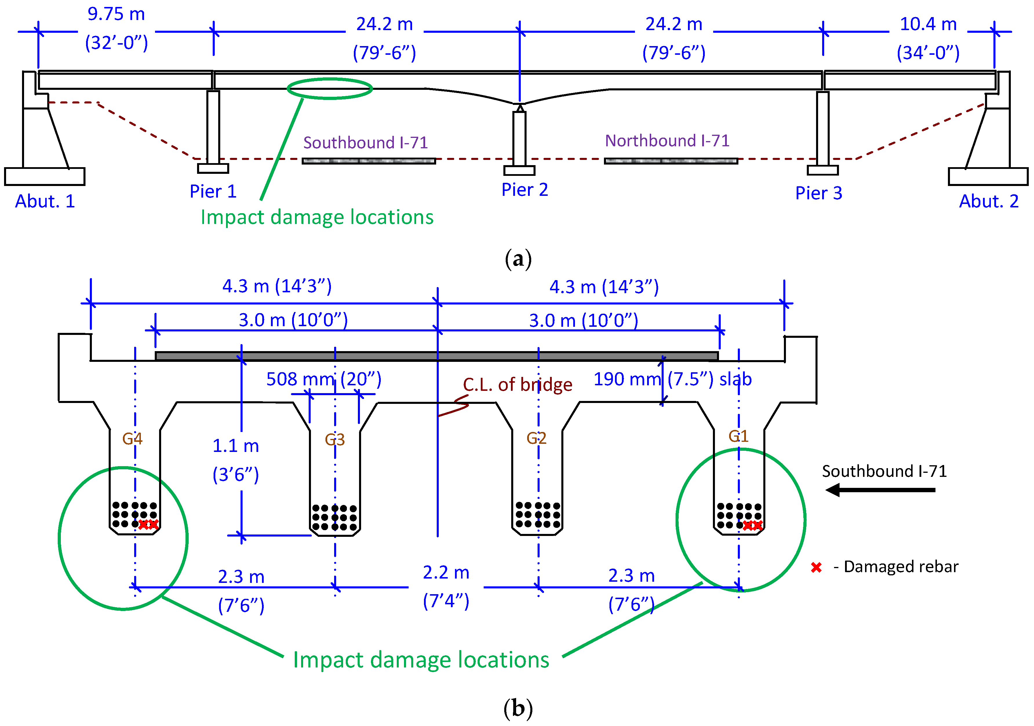
On 13 June 2015, the Kentucky State Police informed the Kentucky Transportation Cabinet (KYTC) that a semi-truck hauling a large piece of equipment had impacted the Mt. Olivet Road overpass bridge over I-71 in Henry County, Kentucky. The four span RC deck-girder bridge was built in 1968, carries the two-lane Mt. Olivet Road (Kentucky State Route KY 3320), and has an Average Daily Traffic (ADT) of approximately 480 vehicles. The layout of the bridge and the cross section at the point of impact are shown in Figure 2. Concrete decks of 190 mm (7.5 in) on each span are supported by four RC girders of variable and constant depth. The two center spans are over the northbound and southbound lanes of I-71, with two lanes of traffic in each direction. Each of the center spans is 24.2 m (79.5 ft) in length, of which 16.5 m (54 ft) is of a constant depth of 1.1 m (3.5 ft), and the remainder of variable depth up to 2.1 m (7 ft). Based on the design stresses listed in the bridge plans, the concrete compressive strength was taken as 20.7 MPa (3000 psi) and the yield strength of the steel rebar was taken as 275.8 MPa (40 ksi).
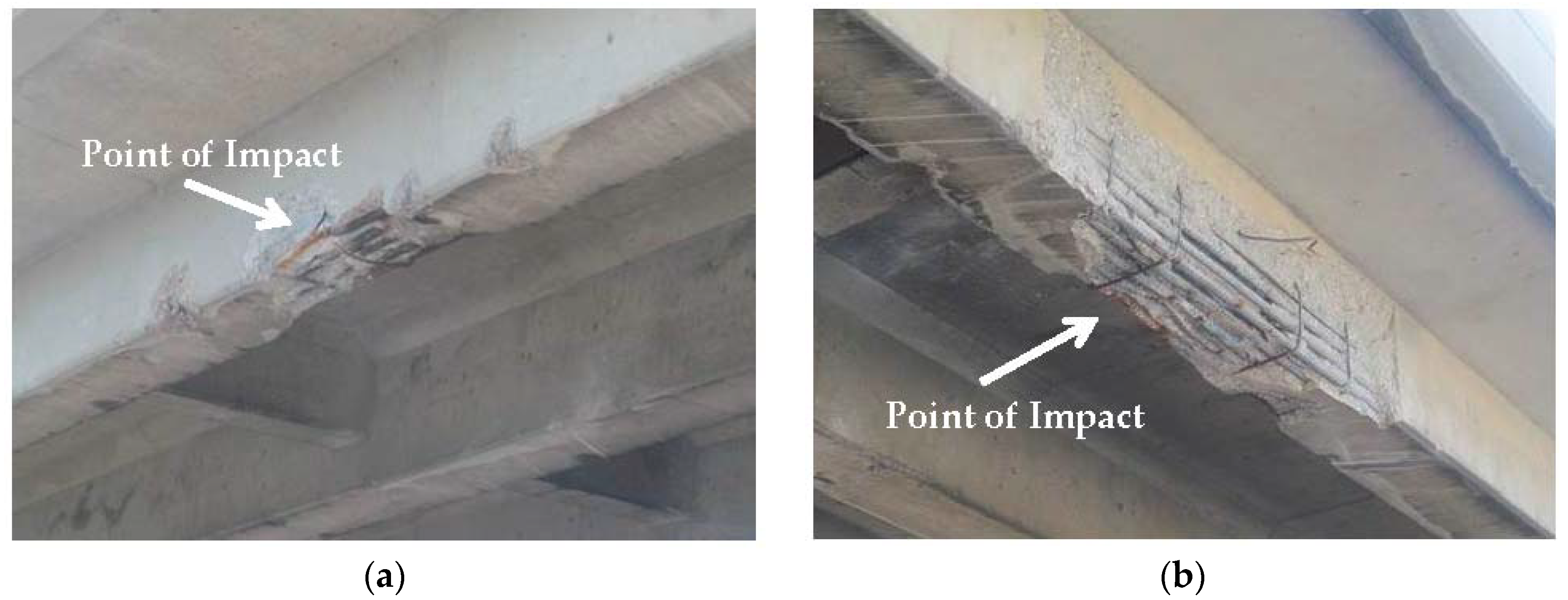
Both exterior girders (G1, G4) over the right lane were impacted, producing spalled concrete and bent reinforcing bars. At the point of impact, the bottom rebar mat of both RC girders consisted of five rebars, each 35.8 mm (1.41 in) in diameter, of which two were bent and yielded (Figure 3). The damaged reinforcement represented 13.3% of the total reinforcing steel available to resist positive bending. Several stirrups for shear reinforcement were also severed during the impact. On both girders, concrete damage to the impacted side appeared minimal, but there was significant concrete cracking and spalling on the girders’ back sides. Girder 4 had the most damage, with the concrete spalling spread across approximately 3.7 m (12 ft).
4. Design of CRP Retrofit
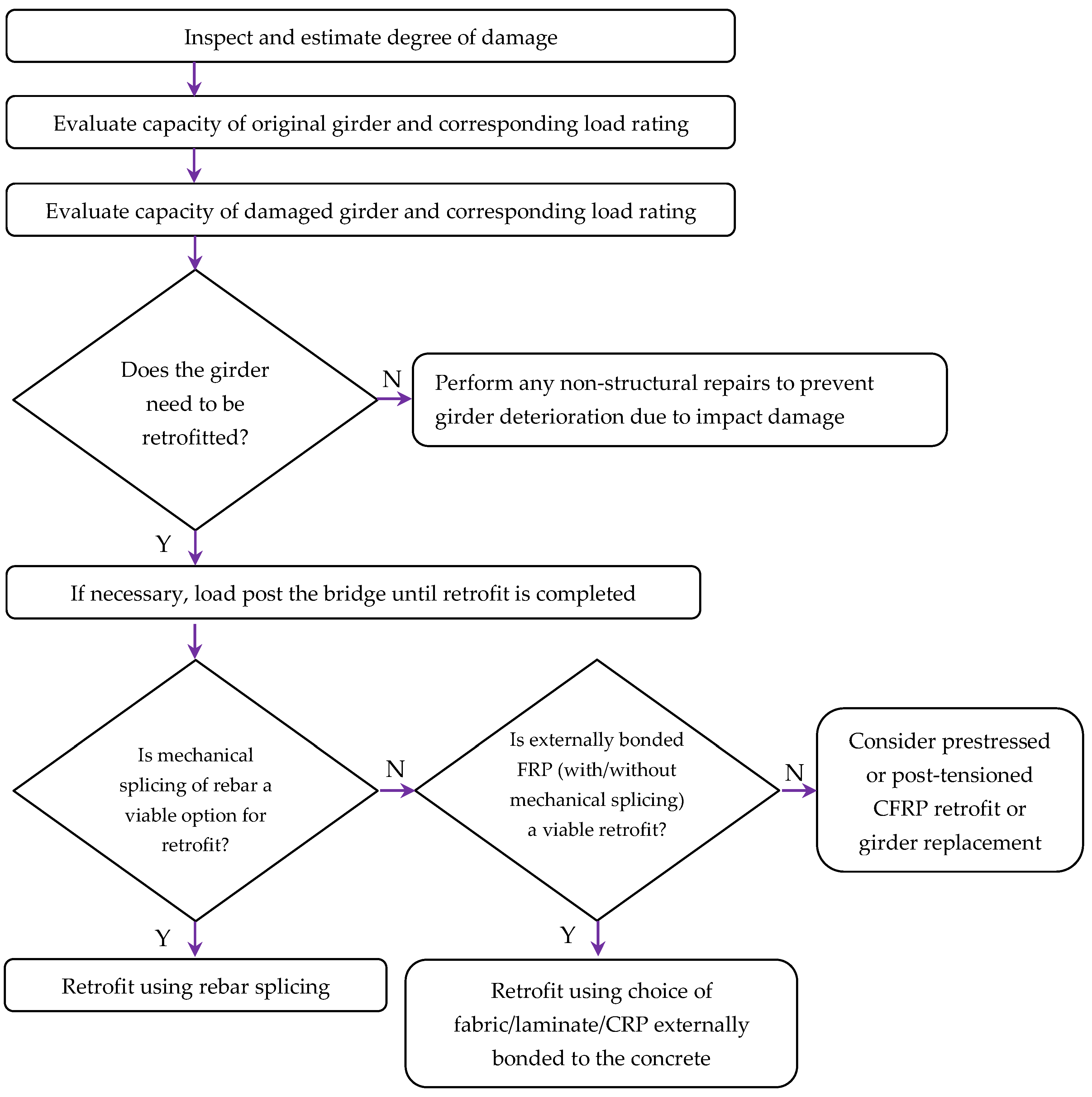
Each over-height impact damage retrofit is unique due to the different variables involved, including damage location, degree of damage, girder support conditions, and load distribution. Figure 4 summarizes the typical steps followed in the retrofit process, provided a significant amount of section loss has occurred from the over-height impact. After the impact was reported, the right lane of I-71 was closed to traffic and the damaged girders inspected. Based on the inspection, and considering the design year of the bridge and the loss of rebar detailed previously, a Load Factor Rating (LFR) based on AASHTO [31] was performed to evaluate if a retrofit was needed. The moment capacities of the exterior RC girders prior to and following the impact, and the retrofitted girder, are provided in Table 2. The load rating was carried out for several truck types; results for the HS20 standard AASHTO truck are shown in Table 2. The inventory load rating for the bridge dropped below 1.0 due to the impact damage. AASHTO requires that exterior girders have the same load carrying capacity as interior girders [32]. KYTC determined that the impact-damaged RC girder needed to be returned to its original capacity.
As traditional mechanical couplers are much larger in diameter than the rebar that they join, it was not possible to couple both rebar (on both beams) while satisfying cover and clearance requirements as the rebar were next to each other and damaged at the same location. The use of mechanical couplers would have required cutting the bent rebar and removing a much larger area of concrete for their insertion. Therefore, mechanical coupling was not viewed as a viable retrofit method for the RC girders, prompting the consideration of externally bonded CFRP (EB-CFRP). While methods like Near Surface Mounted (NSM) CFRP are an alternative, due to the time and labor required for their installation, they were not considered for the over-height impact repair. When evaluating if EB-CFRP can be utilized, current design guides restrict the capacity of the damaged girders that can be retrofitted using externally bonded FRP. AASHTO guidelines [9] specify Equation (1), while the ACI guidelines [8] factor dead and live loads as shown in Equation (2).
where:
- Rr = factored resistance computed in accordance with AASHTO LRFD Section 5
- ηi = 1.0
- DC = force effects due to components and attachments
- DW = force effects due to wearing surface and utilities
- LL = force effects due to live loads
- IM = force effects due to dynamic load allowance
- Rn = nominal strength of member
- φ = strength reduction factor
- SDL = dead load effects
- SLL = live load effects
These code-based restrictions limit the likelihood of catastrophic failure due to deficiencies in the retrofit or debonding of the FRP due to accidental overloading. While in this case the damaged capacity of the current RC girder satisfied the strength requirement of both codes, provided that the limits are not met, practitioners can potentially increase the girder capacity by mechanical coupling of several rebars until the limits are met, prior to FRP strengthening.
With the two-lane southbound I-71 below the impacted girder carrying almost 18,000 vehicles per day, the repair and EB-CFRP strengthening needed to minimize disruptions to traffic flow. While the impact occurred over the right lane of I-71, the potential for the damage and/or strengthening to spread to the section of the girder over the left lane as the retrofit construction progressed was a distinct possibility. While the use of CFRP laminates and fabric were identified as possible strengthening materials, due to the potential for the damage and/or the retrofit to carry over to the section of the girder spanning the adjacent traffic lane externally bonding CRPs were selected as the primary retrofit material.
One of the governing failure modes when using EB-CFRP strengthening is the debonding strain (εfd) limit. The current AASHTO code [9] provides a fixed design strain limit of 0.005 mm/mm (in/in) at the FRP material-concrete interface. The ACI code [8] includes an equation for calculating the debonding strain based on the concrete strength and material and geometric properties of the FRP material (Equation (3)). Because the individual rods that make up the CRP are embedded in the layer of structural epoxy, they are expected to have a greater surface area for bonding to the concrete. While using the AASHTO debonding strain limit for CRPs is straightforward, when utilizing the ACI strain limits the total area of the CFRP rods that make up the CRP (on the bottom face of the beam) is converted to an equivalent laminate having the same width. The calculated thickness is then used to evaluate the debonding strain based on Equation (3). This is expected to provide a conservative debonding strain estimate as the CRPs would be spread over a larger area than an equivalent pultruded laminate of equal capacity. Experimental beam tests have shown a 38% higher load carrying capacity for CRP-strengthened RC beams over similar beams strengthened with pultruded CFRP laminates of equivalent axial stiffness [30].
where:
- f’c = Compressive strength of concrete in MPa (psi)
- n = Number of plies of FRP
- Ef = Tensile modulus of elasticity of FRP in MPa (psi)
- tf = Nominal thickness of one ply of FRP reinforcement in mm (in)
- εfu = design rupture strain of FRP reinforcement (mm/mm) (in/in)
Based on the failure mode governed by debonding strain, provided the EB-CFRP is applied to the bottom surface of the RC girder (below the steel rebar), the amount of CFRP material (Af) required can be conservatively estimated using Equation (4).
where:
- fy = Yield strength of steel rebar in MPa (psi)
- As-d = Damaged rebar area in mm2 (in2)
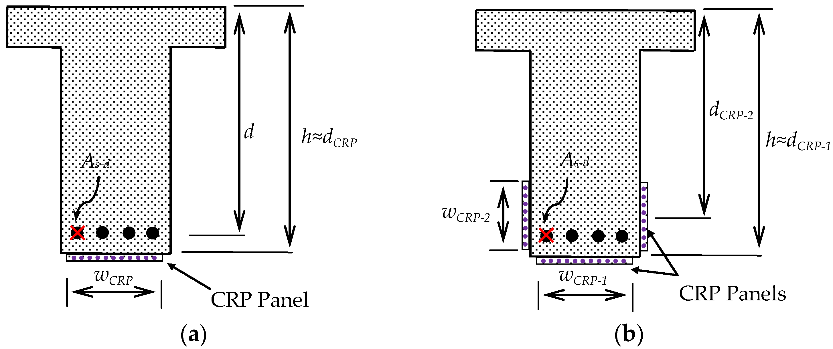
For pultruded CFRP laminates, the required strip width can be calculated by dividing the FRP area calculated from Equation (4) by commercially available laminate thicknesses. For CRPs, however, both the area of individual rods and their spacing need to be considered. The required width of a CRP panel (wCRP in Figure 5a) can be calculated using the information on CRPs provided in Table 1 and Equation (5). The information in Table 1 is for CFRP rods that have been experimentally evaluated by the authors. Note that the use of higher modulus CFRP rods and/or larger diameter rods would reduce the required width of the panels.
where:
- Sr = Rod spacing of CRP panel in mm (in)
- Ar = CFRP rod area in mm2 (in2)
For the two CRP panels shown in Table 1, CRP 070 and CRP 195, the required widths to replace the two damaged rebars in each of the two impacted RC girders were 1700 mm (67 in) and 660 mm (26 in) respectively. As shown in Figure 2, the width of the impact damaged RC girder was 508 mm (20 in), but the width available for applying the CRP on the bottom face was less than that when accounting for the girder’s chamfered edges. Based on the results, it was clear that even when using the larger capacity CRP 195, the panels would also need to be placed along the vertical faces of the girder (Figure 5b) to achieve the desired strengthening. While a single panel on the side of the damaged rebars can be applied, it is advantageous to apply the same sized panels on either side of the beam to maintain symmetry of the retrofit (Figure 5b). As the strain on the CRPs away from the bottom surface would be less than the debonding strain, the required panel widths were estimated using Equation (6). It is practical to use the same size CFRP rods for both the bottom surface and sides (i.e., Ar-1 = Ar-2, sr-1 = sr-2). As the width of the panel at the bottom is known, the equation yields a relationship between the width of the panels on the sides (wCRP-2) and the depth (dCRP-2) at which they are applied. As shown in Figure 1, and discussed previously, alternating CRPs would have an additional rod for symmetry at the finger joint. The strength of the required CRPs is calculated by ignoring the additional CFRP rod.
The same panel width for the CRP 195 was deployed on the bottom and sides of the RC girders (Figure 6). Based on the design calculations, the minimum width for the CRP panels should be equal to or greater than 254 mm (10 in). A width of 356 mm (14 in) was selected for the final design. Based on the initial damage inspection, five panels of CRP 195 were to be applied on the bottom surface and the sides of the RC girder (Figure 6). Following deployment, the five panels had a length of 5.5 m (18 ft). The panels extended a minimum distance of 150 mm (6 in) beyond the damaged areas. Figure 6a shows CFRP U-wraps of a triaxial braided quasi-isotropic (0°, +/−60°) carbon fabric. The U-wraps increase the CRP bond strength [30] and provide additional capacity beyond the one required by the AASHTO design guide [9]. As concrete cover delamination was the observed failure mode for CRPs [27,30], the CFRP U-wraps were expected to increase the capacity of the CRP strengthening system by anchoring the CRP panel ends. Laboratory testing has shown a 25% increase in the ultimate load carrying capacity of RC beams strengthened using CRPs with ends confined with carbon fabric U-wraps when compared to CRP strengthened beams without U-wraps [30]. The fabric’s quasi-isotropic nature was expected to strengthen the cracked areas of the beam irrespective of crack orientation. In addition, the triaxial carbon fabric would also contained crushed concrete in the event of future over-height impacts. Small strips of 150 mm (6 in)-wide uniaxial carbon fabric were utilized as anchor strips for the triaxial U-wraps, at the top of the RC girders (Figure 6a).
The retrofit design utilizing the CRP was carried out using AASTHO [9] and checked with ACI [8] design guidelines. The final retrofit moments, governed by debonding strains, are provided in Table 2. Details regarding the calculation of the retrofit design based on AASHTO [9] are provided in Appendix A. Note that AASHTO’s concrete stress-strain model is only practical for application in girders with rectangular cross sections. While the damaged RC girders were flanged sections, the method was still applicable because the neutral axis was within the flange. The flexural capacity of the RC girders based on AASHTO (MnR-AASHTO) was 3621 kN·m (2671 k·ft), with the CRP utilizing only 30% of its ultimate stress.
5. CRP Retrofit Analysis
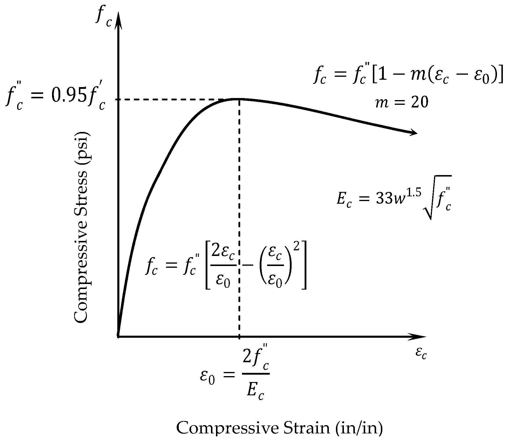
The moment-curvature relationship for the impacted RC girders was derived to better understand the behavior of the girders at the different stages (undamaged, damaged, CRP retrofitted). For a given section, a moment-curvature relationship provides the means to analyze the composite behavior of different materials with either linear or nonlinear material property variations. The moment (M) can be evaluated for increasing strain levels using section analysis, while the gradient of the strain profile, curvature (ϕ), can be evaluated from beam theory. A non-linear concrete model proposed by Ford et al. [33] was utilized to evaluate the concrete stress in compression (Figure 7). The model assumes a bi-linear stress-strain relationship for the reinforcing steel, while the compression rebars within the deck were ignored for simplicity. A linear stress-strain relation was used to model the CFRP material in the CRPs.
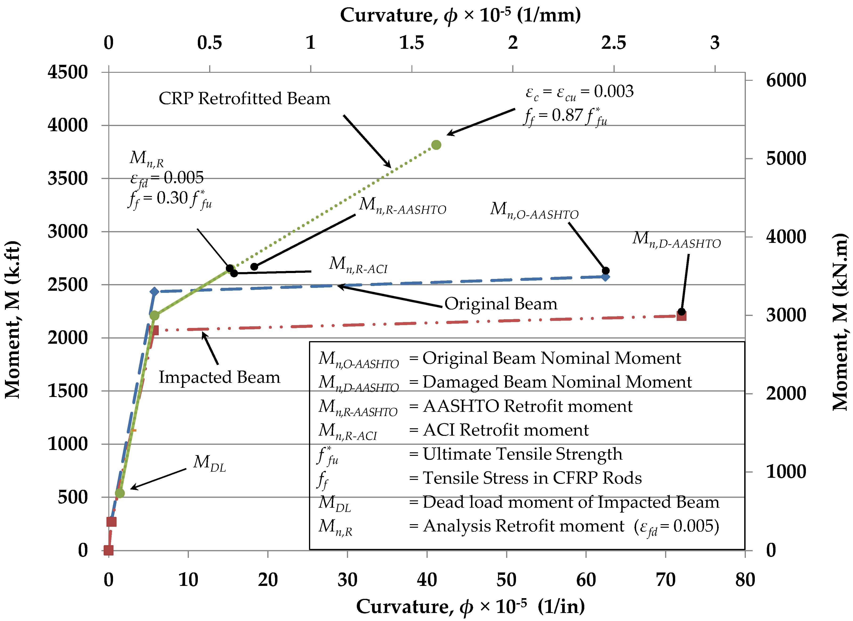
The composite girder section was used in the analysis and, based on the assumption of a linear strain distribution over the depth of the section, the strain levels in the concrete, the steel, and FRP in the retrofit section were calculated for a specific neutral axis depth and strain level in the outermost concrete fiber in compression. The corresponding stresses were calculated and the algebraic sum of the forces computed. This process was iterated for a desired strain state until the forces were in equilibrium. The moment and curvature for both the undamaged and damaged girder were evaluated at the cracking of concrete, yielding of steel rebar, and at ultimate crushing of concrete. The undamaged girder was analyzed first, and then the section properties were modified to account for the loss of rebar from the impact when analyzing the damaged girder. The undamaged rebars were included in the analysis of the damaged section while the damaged concrete, which was located in the cracked region, was excluded from the capacity calculations. When analyzing the retrofitted girder, the damaged girder was modified by incorporating the additional CRP material. The moment-curvature relationships for the impact damaged RC girders at the three different stages are shown in Figure 8.
For the retrofitted girder, analysis was initiated from the location where the damaged girder was subjected to just dead loads. The last point of analysis for the retrofitted girder was at crushing of concrete, where a concrete strain (εc) of 0.003 mm/mm (in/in) was reached, at which point the CRP reached 87% of its ultimate strength of 2200 MPa (320 ksi). Note that this point is purely theoretical as the strain at the CRP-concrete interface was 0.0143 mm/mm (in/in), almost three times the design limit for EB-CFRP. While CRPs should have higher debonding strains than externally bonded CFRP laminates [30], they are expected to be less than the debonding strains for NSM CFRP. While current AASHTO guidelines [9] do not address NSM CFRP, ACI [8] specifies a design debonding strain limit of 0.7εfu. Given the debonding strain limits for NSM CFRP and based on the material properties of the CFRP rods, this results in a debonding strain of 0.0098 mm/mm (in/in). The location where the strain at the CRP-concrete interface was 0.005 mm/mm (in/in), based on AASHTO debonding strain limits for EB-CFRP, is highlighted in Figure 8 as the location of the retrofit moment (Mn,R).
The nominal moments (Table 2) for the undamaged (MnO-AASHTO) and damaged (MnD-AASHTO) girder, as well as the flexural capacity of the CRP-retrofitted girder based on both AASHTO [9] and ACI [8], are plotted in Figure 8. The calculated values are in good agreement with the analysis curves. The results indicated that the CRP increased the moment capacity of the damaged girders beyond the original beam moment capacity.
6. Retrofit Construction
The right lane of the two-lane southbound I-71 was closed at 9 a.m., soon after the morning peak traffic, during each day of the retrofit construction. The retrofit construction was carried out by the KYTC District Bridge Maintenance crew, who had prior experience working with both CRP and CFRP fabric. Damaged girders were accessed using three man-lifts. Each lift accommodated two crew members and equipment. The versatile articulating arms of the man-lifts reached any location within the impact-damaged area of both girders. Using multiple man-lifts let construction proceed at both impact locations simultaneously, reducing lane closure time.
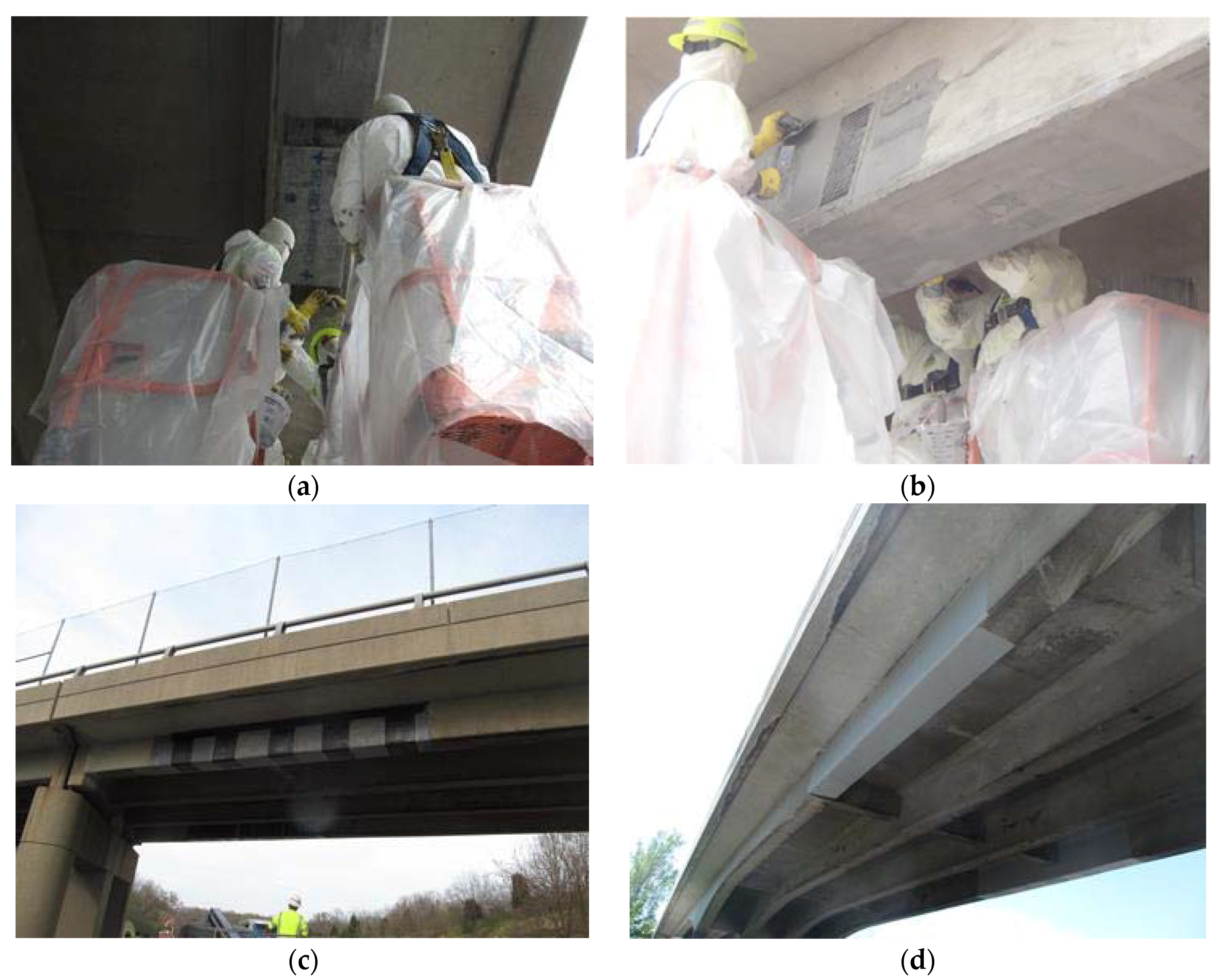
The initial part of the retrofit involved removing deteriorated concrete and bringing the RC girders back to their original shapes. Several of the steps involved in the process are shown in Figure 9. All loose concrete around the impacted area was removed using pneumatic chipping hammers (Figure 9a). Then, a saw cut was made along the periphery of the damaged area, and concrete was removed up to the edge of the cut. Concrete was also removed around all the rebar within the damaged area, exposing a minimum of 25 mm (1 in) of non-corroded steel. Shear reinforcement that had been severed was replaced by splicing a new section. Next, all the steel was grit blasted to remove built-up rust (Figure 9b). The concrete surface where the retrofit material was eventually bonded was grit blasted to establish a clean and profiled bond surface. The steel rebars were then wiped down with a solvent and covered in a primer coating to prevent future corrosion (Figure 9c). The following day wooden form work was set up at both girders for placement of a rapid setting repair mortar (Figure 9d). A rapid setting mortar that can reach a minimum compressive strength of 27.6 MPa (4000 psi) within 24 h was selected to minimize construction duration. The mortar was mixed and inserted through openings left at the top of the formwork. Concrete vibrators were inserted through the openings and placed on the forms to ensure consolidation of the repair mortar. Finally, openings at the top were filled using handheld trowels.
The repair mortar was allowed to cure over a weekend, and once the formwork was removed, remaining voids were filled. Excess material and sharp edges were removed using mechanical grinders to obtain a smooth surface for wrapping the CFRP U-wraps. All the concrete work was completed within five work days.
While the initial estimates for the retrofit called for five panels, following the concrete repair work, it was found that four panels with a total length of 4.4 m (14.5 ft) would span the damaged area. This also eliminated the need to strengthen the girders over the adjacent traffic lane. Prior to applying the CFRP material, the RC girders were cleaned by blowing compressed air and then wiped down using a solvent. A two-part structural epoxy was applied to the concrete surface for bonding the CRPs. The epoxy was spread out evenly over the surface using notched trowels, with the thickness being dependent on the CFRP rod diameter. Achieving the required thickness lets the CFRP rods be pressed into the epoxy and be fully embedded. Excess epoxy was spread out over the top of the panel, covering the entire panel in epoxy, except for the finger joint connecting to the adjacent panel. Unlike the application of CFRP laminates, only the epoxy required for an individual CRP panel needs to be applied. Once a panel was attached, the man-lift was moved over to the location of the adjacent panel and the process repeated. Figure 10a captures the application of a CRP on the bottom surface of a RC girder. Figure 10b shows CRPs being applied on to the sides of the girder following the application of CRPs to the bottom of the girder.
Soon after the CRPs were applied, CFRP U-wraps were placed over the finger joint locations in the CRPs (Figure 10c). A wet layup using a saturating epoxy was employed in the CFRP fabric application. An epoxy primer coat was first applied on the vertical surfaces to prevent the fabric from sliding. As noted earlier, the triaxial CFRP U-wraps were expected to provide additional bond strength to the CRPs. An anchor strip of unidirectional CFRP fabric was placed over the U-wraps at the top of the beam (Figure 10c). The complete retrofit has an ultraviolet (UV) protective coating which was applied over the entire retrofit area after the epoxy had cured (Figure 10d).
Application of the CRP and CFRP fabric was carried out by a crew of eight in a single day. In addition to the two impacted RC girders, this included an additional girder with deteriorated rebar and concrete spalling that was strengthened using CFRP fabric in the adjacent approach span. While strengthening over both lanes of traffic was not required, the use of CRPs provided the option of stopping the retrofit after strengthening over one lane and continuing over the other after diverting traffic. Similarly, if a CRP application cannot be completed in one day, or has to be stopped due to unexpected circumstances, as long as the last finger joint is left void of epoxy, the CRP application can be continued at a later date. This is accomplished by covering the concrete section, where the finger joint would be located, with plastic wrap prior to epoxy application. Once the CRP is placed, a temporary cover (e.g., plastic wrap) is placed over the finger joint.
7. Conclusions
The retrofit design, analysis, and construction of over-height truck impact damaged RC girders using CFRP Rod Panels (CRPs) is presented in this paper. Both exterior RC girders on an overpass over southbound I-71 in Kentucky were impacted by an over-height truck and their reinforcing steel was damaged. CRP 195 panels, with CFRP rods 3.96 mm (0.156 in) in diameter, were selected for the retrofit. CRPs were required on the bottom face and on the sides of the girders to account for the loss of the rebars. The retrofit design was primarily based on AASHTO guidelines for using externally bonded CFRP (EB-CFRP) to strengthen concrete bridge elements. The CRP retrofit replaced all of the capacity lost due to the impact damage. Triaxial (0°, +/−60°) braided quasi-isotropic CFRP fabric U-wraps were applied at the CRP finger joints and panel ends to provide additional bond capacity. The following recommendations are made regarding the use of CRPs for strengthening impact-damaged RC girders:
- An initial estimate of the CRP size needed to replace damaged rebar can be made by calculating an equivalent axial stiffness, where the AASHTO debonding strain limits are utilized to estimate the CRP capacity.
- Although CRPs are experimentally shown to have a higher debonding strain than EB-CFRP, until additional experimental data is available, designs for strengthening RC bridge girders using CRPs should be conservatively based on AASHTO guidelines for EB-CFRP.
- The amount of strengthening that can be achieved using CRP may be limited by the available concrete bond area. In the future, this may be offset by increased debonding strain limits based on additional laboratory tests. Larger rods and higher modulus rods should be evaluated for their applicability in increasing the CRP capacity.
- As demonstrated by this project, the CRP application can be carried out by a two-person crew working from a mobile work platform/man-lift. This reduces the amount of manpower and equipment typically required with EB-CFRP. Additional crew members and construction equipment can be used to expedite the repair, especially when repairs are impacting congested roadways.
- The modular construction of the CRP, which gives crews the ability to halt strengthening after any CRP application, and resume at a later date, provides a significant advantage when working on bridges over multi-lane roadways. This may also be advantageous when strengthening long spans with limited construction access, such as those over waterways.
Author Contributions
The retrofit design was carried out by both A.P. and I.H. The retrofit construction was supervised by A.P., while the overall project management was done by I.H. The manuscript was written by A.P. and reviewed by I.H.
Acknowledgments
Funding for the project was by the Kentucky Transportation Cabinet (KYTC) and the Federal Highway Administration (FHWA). The retrofit construction and traffic control was carried out by personnel from KYTC District 05.
Conflicts of Interest
The authors declare no conflict of interest. The funding sponsors had no role in the design of the study; in the collection, analyses, or interpretation of data; in the writing of the manuscript, and in the decision to publish the results.
Appendix A
This Appendix presents the flexural design calculations for the retrofitted RC girders identified in Figure 2 and Figure 3. CFRP rod panels (CRP) are used for the retrofit and the beam analysis is based on AASHTO EB-CFRP guidelines [9]. The compressive steel reinforcing has been ignored in the calculations.

Table A1.
CRP retrofit design calculations.
| Girder and Section Properties of Damaged Girder | Metric Units | Inch-Pound Units |
| Clear span of girder (l) | 24.2 m | 79.6 ft |
| Effective width of deck (be) | 2.3 m | 90 in |
| Height of deck (hd) | 190 mm | 7.5 in |
| Height of girder (including deck) (hc) | 1.07 m | 42 in |
| Cracked section moment of inertia (Icr) | 0.0552 m4 | 132,678 in4 |
| Depth to cracked section N.A (kd) | 255 mm | 10.05 in |
| Girder section area (Ac) | 0.7516 m2 | 1165 in2 |
| Area of (remaining) steel (As) | 13,084 mm2 | 20.28 in2 |
| Depth to centroid of (remaining) steel (d) | 0.874 m | 34.4 in |
| Total FRP area of CRP (Af) Three 356 mm (14″) panels contain 38 rods each. Each rod is 12 mm2 (0.019 in2) | 1406 mm2 | 2.18 in2 |
| Equivalent depth to centroid all CRP (df) The two side panels are placed 25 mm (1 in) above the bottom surface to account for the chamfer. | 0.932 m | 36.7 in |
| Material Properties | Metric Units | Inch-Pound Units |
| Concrete modulus of elasticity (Ec) | 22.89 GPa | 3320 ksi |
| Concrete compressive strength (f’c) | 20.7 MPa | 3000 psi |
| Steel modulus of elasticity (Es) | 200 GPa | 29,000 ksi |
| Yield stress of steel (fy) | 276 MPa | 40 ksi |
| CRP FRP modulus of elasticity (Ef) | 134.4 GPa | 19,500 ksi |
| Ultimate FRP tensile strength (ffu*) | 2206 MPa | 320 ksi |
| Ultimate FRP rupture strain (εfu*) | 0.0164 mm/mm | 0.0164 in/in |
| Loading at Impact Location | Metric Units | Inch-Pound Units |
| Dead load moment (including barrier wall) (MDL) | 705 kN·m | 520 k·ft |
| Live load moment (edge beam) (MLL) | 988 kN·m | 729 k·ft |
| Impact Factor | 0.244 | 0.244 |
| Design | Metric Units | Inch-Pound Units |
| Step 1: Calculate CRP design material properties Since the CRP retrofit is on the bridge’s edge girder and will be directly exposed to the elements, an environmental reduction factor of 0.85 is used. ffu = 0.85ffu* εfu = 0.85εfu | 1875 MPa 0.0139 mm/mm | 272 ksi 0.0139 in/in |
| Step 2: Existing state of strain at FRP installation (εbi) Assuming that the beam is uncracked, and only dead loads exist at the time of FRP application, the existing strain at the bottom of the girder (εbi) is calculated. | 0.00038 mm/mm | 0.00038 in/in |
| Step 3: Estimate depth to neutral axis (c) An initial assumption of the neutral axis depth (c) is taken as 20% of the height of the composite girder. c = 0.2 hc | 213 mm | 8.4 in |
| Step 4: Determine effective level of strain in CRP (εfe) The maximum strain that the CRP can reach is governed by the strain limits due to either concrete crushing (εcu = 0.003), FRP rupture or FRP debonding. | ||
| Debonding | 0.005 mm/mm | 0.005 in/in |
| FRP strain at concrete crushing | 0.0097 mm/mm | 0.0097 in/in |
| FRP strain at rupture εfu = 0.0139 | 0.0139 mm/mm | 0.0139 in/in |
| The effective level of strain in the CRP (εfe) is the lesser of the debonding strain (εfd = 0.005 mm/mm), FRP strain at concrete crushing (εfu = 0.097 mm/mm), and the rupture strain (εfu = 0.0139 mm/mm) from the material properties. Therefore, effective level of strain εfe = εfd | 0.0050 mm/mm | 0.0050 in/in |
| Step 5: Calculate the stress in the CRP (ff) The stress is calculated based on the linear stress-strain relationship: | 672 MPa | 97.5 ksi |
| Step 6: Calculate the strain in the concrete (εc) The strain in the concrete is calculated using similar triangles: | 0.0016 mm/mm | 0.0016 in/in |
| Step 7: Calculate the strain in the steel (εs) The strain in the steel rebars is calculated using similar triangles: | 0.00495 mm/mm | 0.00495 in/in |
| Step 8: Calculate the stress in the steel (fs) The stress is calculated based on bi-linear stress-strain relationship: | 276 MPa | 40 ksi |
| Step 9: Calculate the equivalent concrete compressive stress block parameter (β2) This factor will be used to check the internal force equilibrium. | ||
| The strain at f’c is calculated (εo) | 0.00154 mm/mm | 0.00154 in/in |
| Average stress block parameter calculated from the parabolic stress-strain relationship for concrete: | 0.703 | 0.703 |
| Step 10: Calculate the internal force resultants and check equilibrium The calculated value is checked with the assumed value of c in Step 3. | 152 mm | 5.99 in |
| Step 11: Adjust c until force equilibrium is satisfied The value for c in Step 9 is within the deck (c ≤ hd) and is different from the value assumed in Step 3. Iterate starting from Step 3 until equilibrium is reached. Note: The AASHTO specifications may not be practical for the application of flanged sections when the neutral axis falls outside of the flange. | 173 mm | 6.83 in |
| Step 12: Calculate flexural strength components The contributions from the reinforcing steel and CRP to the beam flexural strength are calculated. The multiplier for locating the resultant of the compression force in the concrete (k2): | 0.367 | 0.367 |
| Reinforcing steel component (Mns) | 2923 kN·m | 2156 k·ft |
| FRP component (Mnf) | 820 kN·m | 605 k·ft |
| Step 13: Calculate flexural strength (Mr) An additional reduction factor φfrp = 0.85 is applied for flexural strength contribution of the CRP. | 3621 kN·m | 2671 k·ft |
| Step 14: Calculate design flexural strength (ϕMr) Design flexural strength (ϕMn) with ϕ = 0.9 reduction factor: Note: The ϕ factor is only applied to the steel component | 2752 kN·m | 2030 k·ft |
References
- Shanafelt, G.O.; Horn, W.B. NCHRP Report 271: Guidelines for Evaluation and Repair of Damaged Steel Bridge Members; Transportation Research Board of the National Academies: Washington, DC, USA, 1984. [Google Scholar]
- Shanafelt, G.O.; Horn, W.B. NCHRP Report 226: Damage Evaluation and Repair Methods for Prestressed Concrete Bridge Members; Transportation Research Board of the National Academies: Washington, DC, USA, 1980. [Google Scholar]
- Shanafelt, G.O.; Horn, W.B. NCHRP Report 280: Guidelines for Evaluation and Repair of Prestressed Concrete Bridge Members; Transportation Research Board of the National Academies: Washington, DC, USA, 1985. [Google Scholar]
- Harries, K.A.; Miller, R. NCHRP 20-07/Task 307: Updated Research for Collision Damage and Repair of Prestressed Concrete Beams; Transportation Research Board of the National Academies: Washington, DC, USA, 2012. [Google Scholar]
- Harik, I.; Peiris, A. Repair of impacted concrete bridge beams. In Proceedings of the 37th Symposium of the International Association for Bridge and Structural Engineering (IABSE-14), Madrid, Spain, 3–5 September 2014. [Google Scholar]
- Zobel, R.S.; Jirsa, J.O.; Fowler, D.W.; Carrasquillo, R.L. Evaluation and Repair of Impact-Damaged Prestressed Concrete Bridge Girders; FHWA/TX-97/1370-3F; Center for Transportation Research, the University of Texas: Austin, TX, USA, 1997. [Google Scholar]
- Feldman, L.R.; Jirsa, J.O.; Kowal, E.S. Repair of bridge impact damage. Concr. Int. 1998, 20, 61–66. [Google Scholar]
- American Concrete Institute (ACI) Committee 440, Guide to the Design and Construction of Externally Bonded FRP Systems for Strengthening Concrete Structures; ACI 440.2R-08; American Concrete Institute: Farmington Hills, MI, USA, 2008.
- American Association of State Highway and Transportation Officials (AASHTO). Design of Bonded FRP Systems for Repair and Strengthening of Concrete Bridge Elements, 1st ed.; American Association of State Highway and Transportation Officials (AASHTO): Washington, DC, USA, 2012. [Google Scholar]
- Japan Society of Civil Engineers (JSCE). Recommendation for Upgrading of Concrete Structures with Use of Continuous Fiber Sheets; Concrete Engineering Series 41; Japan Society of Civil Engineers (JSCE): Tokyo, Japan, 2001. [Google Scholar]
- International Federation for Structural Concrete (FIB) Task Group 9.3, Externally Bonded FRP Reinforcement for RC Structures; FIB Bulletin 14; FIB: Lausanne, Switzerland, 2001.
- Stallings, J.M.; Tedesco, J.W.; El-Mihilmy, M.; McCauley, M. Field Performance of FRP Bridge Repairs. ASCE J. Bridge Eng. 2000, 5, 107–113. [Google Scholar] [CrossRef]
- Choo, C.C.; Zhao, T.; Harik, H. Flexural retrofit of a bridge subjected to overweight trucks using CFRP laminates. Compos. Part B Eng. 2007, 38, 732–738. [Google Scholar] [CrossRef]
- National Cooperative Highway Research Program, Transportation Research Board (NCHRP). Updated Research for Collision Damage and Repair of Prestressed Concrete Beams; NCHRP 20-07/Task 307; NCHRP: Washington, DC, USA, 2012. [Google Scholar]
- Schiebel, S.; Parretti, R.; Nanni, A. Repair and Strengthening of Impacted PC Girders on Bridge A4845 Jackson County, Missouri; Report No. RDT01-017; Missouri Department of Transportation: Jackson City, MO, USA, 2001. [Google Scholar]
- Wipf, T.J.; Klaiber, F.W.; Rhodes, J.D.; Kempers, B.J. Effective Structural Concrete Repair—Volume 1 of 3: Repair of Impact Damaged Prestressed Concrete Beams with CFRP; Iowa DOT Project TR-428; Iowa Department of Transportation: Ames, IA, USA, 2004.
- Yang, D.; Merrill, B.D.; Bradberry, T.E. Texas’ use of CFRP to repair concrete bridges. In ACI SP 277: Recent Advances in Maintenance and Repair of Concrete Bridges; Kim, Y.J., Ed.; American Concrete Institute: Farmington Hills, MI, USA; pp. 39–57.
- Nanni, A. Strengthening of an Impact-Damaged PC Girder. Available online: https://cdn.ymaws.com/www.icri.org/resource/resmgr/crb/2004mayjun/CRBMayJune04_Nanni.pdf (accessed on 10 July 2018).
- Nanni, A.; Huang, P.C.; Tumialan, J.G. Strengthening of impact-damaged bridge girder using FRP Laminates. In Proceedings of the Ninth International Conference on Structural Faults and Repair, London, UK, 4–6 July 2001; Forde, M.C., Ed.; CD-ROM. Engineering Technics Press: Edinburgh, UK, 2001. [Google Scholar]
- Aidoo, J.; Harries, K.A.; Petrou, M.F. Full-scale experimental investigation of repair of reinforced concrete interstate bridge using CFRP material. ASCE J. Bridge Eng. 2006, 11, 350–358. [Google Scholar] [CrossRef]
- Pino, V.; Nanni, A.; Arboleda, D.; Robert-Wollmann, C.; Cousins, T. Repair of damaged prestressed concrete girders with FRP and FRCM composites. ASCE J. Compos. Constr. 2017, 21, 04016111. [Google Scholar] [CrossRef]
- Cerullo, D.; Sennah, K.; Hossein, A.; Lam, C.; Fam, A.; Tharmabla, B. Experimental study on full-scale pretensioned bridge girder damaged by vehicle impact and repaired with fiber-reinforced polymer technology. ASCE J. Compos. Constr. 2013, 17, 662–672. [Google Scholar] [CrossRef]
- Michels, J.; Michał Staśkiewicz, C.C.; Renata, K.; Yunus, E.H.; Masoud, M. Prestressed CFRP strips for concrete bridge girder retrofitting: Application and static loading test. J. Bridge Eng. 2016, 21, 04016003. [Google Scholar] [CrossRef]
- Kim, Y.J.; Green, M.F.; Fallis, G.J. Repair of bridge girder damaged by impact loads with prestressed CFRP sheets. ASCE J. Bridge Eng. 2008, 13, 15–23. [Google Scholar] [CrossRef]
- Casadei, P.; Galati, N.; Boschetto, G.; Tan, K.Y.; Nanni, A.; Galecki, G. Strengthening of impacted prestressed concrete bridge I-Girder using prestressed near surface mounted C-FRP Bars. In Proceedings of the 2nd International Congress, Fédération Internationale du Béton (FIB), Naples, Italy, 5–8 June 2006; pp. 1–10. [Google Scholar]
- Stallings, J.M.; Porter, N.M. Experimental investigation of lap splices in externally bonded carbon fiber-reinforced plastic plates. ACI Struct. J. 2003, 100, 3–10. [Google Scholar]
- Peiris, A.; Harik, I.E. CFRP rod panels for strengthening concrete bridges. Adv. Struct. Eng. 2018, 21, 557–570. [Google Scholar] [CrossRef]
- Peiris, A.; Harik, I.E. CFRP rod panels for strengthening concrete bridge components. In Proceedings of the Second Congress on Forensic Engineering and Sixth Congress on Collapses, Reliability and Retrofit of Structures (IF CRASC 15), Rome, Italy, 14–16 May 2015; pp. 533–541. [Google Scholar]
- Jawdhari, A.; Peiris, A.; Harik, I.E. Bond study on CFRP rod panels externally adhered to concrete. J. Compos. Constr. 2017, 21, 04016114. [Google Scholar] [CrossRef]
- Jawdhari, A. Behavior of RC Beams Strengthened in Flexure with Spliced CFRP Rod Panels. Ph.D. Thesis, University of Kentucky, Lexington, KY, USA, 2016. [Google Scholar] [CrossRef]
- American Association of State Highway and Transportation Officials (AASHTO). The Manual for Bridge Evaluation, 2nd ed.; AASHTO: Washington, DC, USA, 2016. [Google Scholar]
- American Association of State Highway and Transportation Officials (AASHTO). Standard Specifications for Highway Bridges, 17th ed.; AASHTO: Washington, DC, USA, 2002. [Google Scholar]
- Ford, J.S.; Chang, D.C.; Breen, J.E. Behavior of concrete columns under controlled lateral deformation. ACI J. 1981, 78, 3–20. [Google Scholar]
Figure 1.
CFRP Rod Panels (CRPs) with finger joint.

Figure 2.
(a) General layout of the bridge; (b) Cross section of the bridge at impact location.

Figure 3.
Impact damaged reinforced concrete (RC) girders (a) Impact side of Girder G1; (b) Back side of Girder G4.
Figure 3.
Impact damaged reinforced concrete (RC) girders (a) Impact side of Girder G1; (b) Back side of Girder G4.

Figure 4.
RC girder retrofit process following over-height truck impact.

Figure 5.
CRP application (a) On bottom surface; (b) On bottom surface and sides.

Figure 6.
CRP retrofit design (a) Section of RC girder; (b) Bottom surface view of CRP on girder.
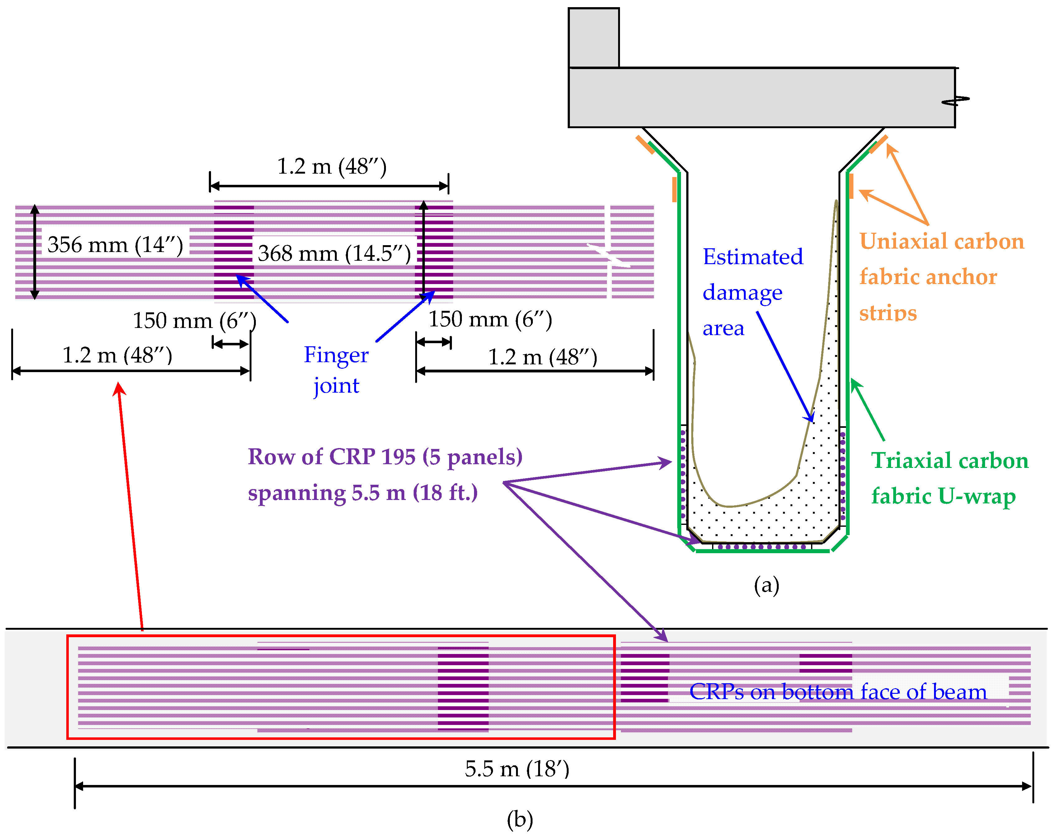
Figure 7.
Concrete model.

Figure 8.
Moment-Curvature response of undamaged, damaged and retrofitted cross-sections.

Figure 9.
Concrete repair of RC girders (a) Remove loose concrete; (b) Grit blasting steel rebar; (c) Application of primer coating on rebar; (d) Setting up formwork for repair mortar.
Figure 9.
Concrete repair of RC girders (a) Remove loose concrete; (b) Grit blasting steel rebar; (c) Application of primer coating on rebar; (d) Setting up formwork for repair mortar.
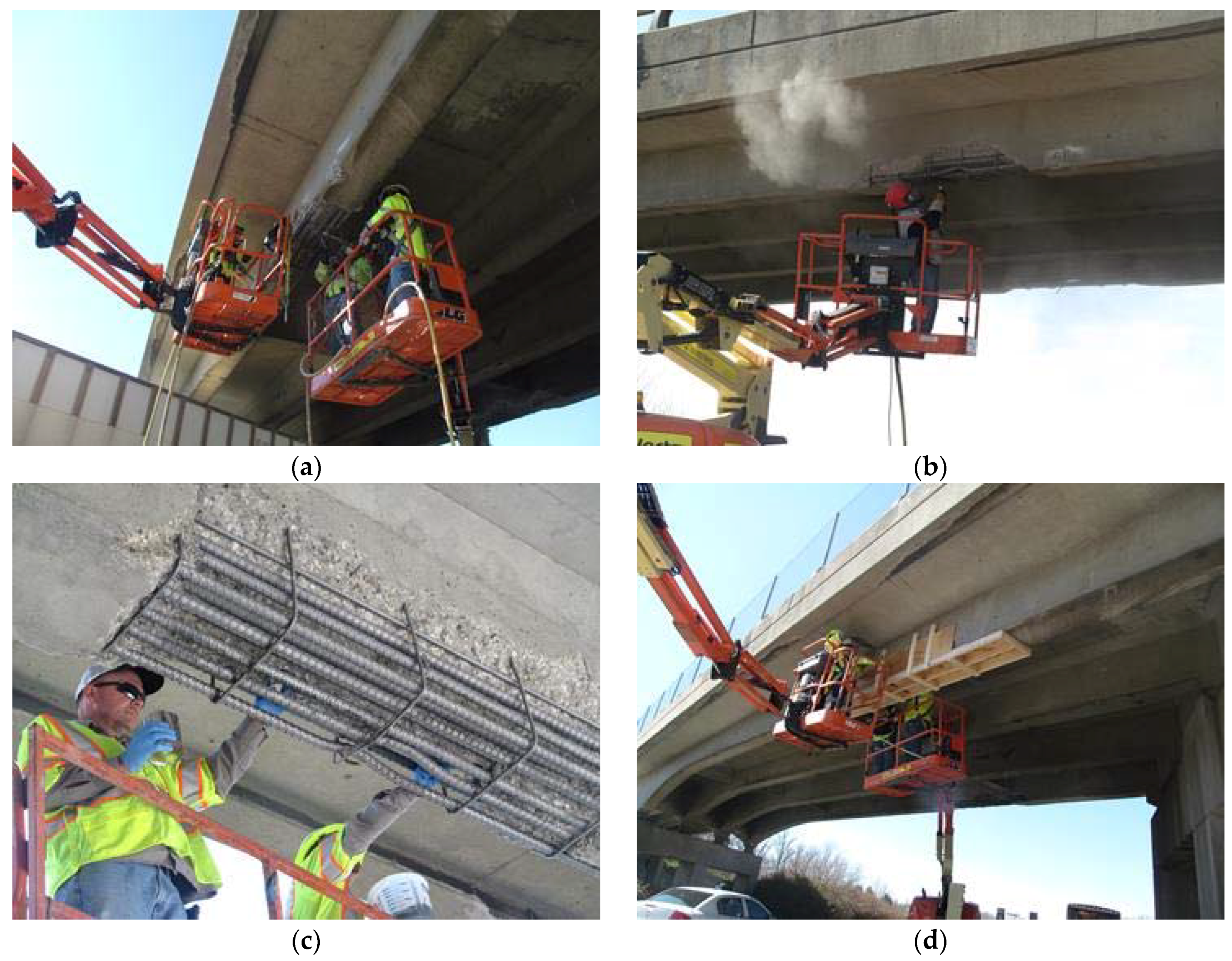
Figure 10.
CFRP Strengthening (a) CRP applied to bottom surface; (b) Covering CRP on sides; (c) CFRP U-wraps and anchor strips applied over CRPs; (d) Ultraviolet (UV) protective coating applied over retrofit.
Figure 10.
CFRP Strengthening (a) CRP applied to bottom surface; (b) Covering CRP on sides; (c) CFRP U-wraps and anchor strips applied over CRPs; (d) Ultraviolet (UV) protective coating applied over retrofit.

Table 1.
CFRP Rod Panel (CRP) properties for two different rod sizes.
| Designation | Rod Diameter, dr | Rod Area, Ar | Rod Spacing, sr | Tensile Strength | Tensile Modulus | |||||
|---|---|---|---|---|---|---|---|---|---|---|
| mm | in | mm2 | in2 | mm | in | MPa | ksi | GPa | ksi | |
| CRP 070 | 1.98 | 0.078 | 3.08 | 4.78 × 10⁻³ | 6.5 | 0.250 | 2200 | 320 | 134 | 19,500 |
| CRP 195 | 3.96 | 0.156 | 12.33 | 19.11 × 10⁻³ | 9.5 | 0.375 | ||||
Table 2.
RC girder capacity at different stages of retrofit.
| Girder State | Moment Identification 1 | Moment Capacity | Concrete Strain | FRP Stress (ff/ffu) | HS20 Inventory Rating | HS20 Operating Rating | |
|---|---|---|---|---|---|---|---|
| kN·m | k·ft | mm/mm (in/in) | |||||
| Undamaged | Mn,O-AASHTO | 3523 | 2599 | 0.00300 | - | 1.08 | 1.80 |
| Damaged | MnD-AASHTO | 3015 | 2224 | 0.00300 | - | 0.87 | 1.45 |
| Retrofit | MnR-AASHTO | 3621 | 2671 | 0.00123 | 0.30 | 1.12 | 1.87 |
| MnR-ACI | 3555 | 2622 | 0.00107 | 0.27 | 1.09 | 1.82 | |
1Mn,O-AASHTO = Original girder moment based on AASHTO; MnD-AASHTO = Damaged girder moment based on AASHTO; MnR-AASHTO = Retrofitted girder moment based on AASHTO; MnR-ACI = Retrofitted girder moment based on ACI.
© 2018 by the authors. Licensee MDPI, Basel, Switzerland. This article is an open access article distributed under the terms and conditions of the Creative Commons Attribution (CC BY) license (http://creativecommons.org/licenses/by/4.0/).
Share and Cite
MDPI and ACS Style
Peiris, A.; Harik, I. Design and Construction of CFRP Rod Panel Retrofit for Impacted RC Bridge Girders. J. Compos. Sci. 2018, 2, 40. https://doi.org/10.3390/jcs2030040
AMA Style
Peiris A, Harik I. Design and Construction of CFRP Rod Panel Retrofit for Impacted RC Bridge Girders. Journal of Composites Science. 2018; 2(3):40. https://doi.org/10.3390/jcs2030040
Chicago/Turabian StylePeiris, Abheetha, and Issam Harik. 2018. "Design and Construction of CFRP Rod Panel Retrofit for Impacted RC Bridge Girders" Journal of Composites Science 2, no. 3: 40. https://doi.org/10.3390/jcs2030040