On the Formation and Distribution of In Situ Synthesized TiB2 Reinforcements in Cast Aluminium Matrix Composites


1
Dipartimento di Meccanica, Politecnico di Milano, 20133 Milan, Italy
2
Department of Metallurgy and Materials Science, College of Engineering Pune, Pune 411005, India
*
Author to whom correspondence should be addressed.
J. Compos. Sci. 2018, 2(3), 52; https://doi.org/10.3390/jcs2030052
Submission received: 5 June 2018
/
Revised: 9 August 2018
/
Accepted: 9 August 2018
/
Published: 3 September 2018
(This article belongs to the Special Issue Advances in Synthesis, Structure and Properties of Metal Matrix Composites)
Abstract
:Introduction of TiB2 reinforcements into aluminium matrices allows composites to be obtained that exhibit excellent mechanical properties and good wear and corrosion resistance. These composites find applications in the automotive, aerospace and marine industries. In the present work, the in situ synthesis of ultrafine TiB2 particulates in an aluminium matrix was accomplished by reaction synthesis of TiB2 using K2TiF6 and KBF4 (in 120% excess to the stoichiometrically needed) fluxes in pre-melted aluminium. Composites were prepared with different concentrations of TiB2 in (2.5, 5 and 10 wt %) in an aluminium matrix. The holding time of the molten composite in an induction furnace was varied from 10 min to 50 min. The in situ formation of TiB2 reinforcement and its distribution in cast aluminiummatrix composites was analyzed based on microstructural studies, microhardness measurements and wear tests. The exothermic reaction between the halide fluxes starts after 10 min of holding time and completes before 20 min of holding time. The dominant phase was TiB2 after 20 min of holding time, while the formation of Ti3B4 was observed as the holding time was extended. The distribution of the reinforcing phases was studied by analyzing the scanning electron microscopy (SEM) images. An optimum holding time (20 min) of the composite melt was determined based on the dominant wear mechanism, microhardness, and phase composition of the composites.
1. Introduction
Master alloys of Ti and B are used for grain refinement of aluminium alloys to improve their mechanical properties [1]. Ceramic reinforcements, such as Al2O3, SiC, AlN, TiC, TiB2 and B4C, are used for aluminium metal matrix composites (Al-MMCs) [2,3]. The ex situ addition of these reinforcements to the aluminium matrix has drawbacks, such as agglomerations, poor wetting, and heterogeneities in the microstructure of the composites. The in situ formation of reinforcements—particularly TiB2 via halide salt reactions in molten aluminium—is attractive due to fine sizes of the synthesized particles, clean interface and improved wettability. Wear resistance (particularly, abrasive and erosive) increases with the progressive addition of TiB2 reinforcing particles in aluminium matrix composites [4]. Apart from these structural characteristics, TiB2 particles have higher thermal conductivity and stability at elevated temperatures than other reinforcements commonly used reinforcements for aluminium matrix composites [5]. Some of the synthesis systems for Al-TiB2 composites are TiO2-Al-B, TiO2-Al-B-CuO, TiO2-Al-B2O3, NaBH4 and TiCl4 and Ti-containing and B-containing salts. The synthesis occurs via a series of chemical reactions which produce sub-micron TiB2 particles in the aluminium melt [6,7,8]. Different techniques/methods such as powder metallurgy, spray deposition and several casting methods (rheo-casting, squeeze-casting, stir-casting and compo-casting) are used to obtain TiB2 reinforcement in aluminium matrices. Stir-casting is the most common technique for the synthesis of Al-MMCs [9,10].
The dispersion of TiB2 particulates in liquid aluminium and its alloys is greatly influenced by the surface tension of the alloy. Nano-scaled TiB2 particles agglomerate to reduce their surface energy [11]. Reinforcement particles in the form of clusters create a discontinuous TiB2 phase in aluminium matrices; the clusters have irregular shapes and different sizes. This results in the formation of particle-rich and particle-depleted regions in TiB2 reinforced aluminium matric composites [12]. Agglomerations of the reinforcement phase have a negative effect on tensile strength, microhardness and wear properties of metal matrix composites [13,14]. Clustering behavior of TiB2 particles in aluminium is studied elsewhere through rapid extraction and solidification techniques [15]. In Reference [15], the melt was held for different holding times, and clustering of the particles was monitored [15]. Induction melting allows the melting temperature of aluminium to be reached within a short time. In molten metals, induction phenomena create several harmonic or periodical electromagnetic fields resulting in the formation of temperature and flow fields [16,17]. These flow fields enable stirring of molten composites without any mechanical stirrer. The critical melt velocity separates out clustered TiB2 particles in aluminium and aluminium alloys [18].
The published literature so far provides limited understanding of the development of aluminium metal matrix composite, particularly in the context of alteration of their properties with respect to the holding time of the melt in the induction fields. This was a motivation for the present work, which demonstrates the effect of the holding time on the microstructure and chemical and structural characteristics of the aluminium matrix composites reinforced with in situ synthesized TiB2 particles. An optimal holding time of the melt, ensuring the formation of composites with improved mechanical performance and wear resistance, was found.
2. Materials and Methods
2.1. Materials and Synthesis of Composite
Aluminium matrix composites with 2.5, 5 and 10 wt % of TiB2 particles were produced by the flux-assisted in situ synthesis (FAS) method. The formation of the TiB2 reinforcement in composite depends on the thermodynamics and kinetics of the reaction between the halide fluxes and molten aluminium. Many combinations of fluxes are available [7]. In the present work, K2TiF6 and KBF4 were used for the synthesis of Al-TiB2 composites. Reactions (1) and (2) illustrate the formation of TiB2 in molten aluminium:
K2TiF6 + 2KBF4 + (22/3) Al ≥ TiAl3 + AlB2 + 3KAlF4 + (1/3) K3AlF6
AlB2 + TiAl3 ≥ TiB2 + 4Al
Reaction (2) describes the formation of TiB2 particulate reinforcement in the liquid aluminium. However, the recovery of boron is lower than predicted by Reaction (1), if the KBF4 flux is added in the stoichiometric proportion. It results in the unbalanced formation of intermetallic constituents—AlB2 and TiAl3. To increase the recovery of boron, KBF4 was taken with an excess of 20% relative to the stoichiometric amount to obtain TiB2 and avoid the formation of other phases [19]. The amount of fluxes and aluminium required to form different concentrations of the TiB2 in Al-MMC (for a batch of 200 g) is provided in Table 1.
In the case of Al-5%TiB2 composite, aluminium (202.94 g) was melted in an induction furnace (25 KW, make Autocontrol, Mumbai, India) and degassed. Fluxes, K2TiF6 (34.14 g) and KBF4 (43.36 g) were mixed together and then added to molten aluminium. The melt was allowed to form TiB2 via reaction synthesis of fluxes and stirred for a different holding time. The melt temperature was measured using a K-type thermocouple (chromel–alumel) after 10, 20, 30, 40 and 50 min of holding time. The aluminium MMCs melts were degassed in the crucible using cryolite slag formers; slag was skimmed before pouring the melt into the metallic mold. For each holding time of cast composites, the experiment was repeated three times to get three cylindrical rods with diameter 20 mm and length 200 mm for corresponding holding times. These raw composites were shaped to cylindrical samples of 10 mm diameter and 10 mm height for subsequent investigation.
2.2. Characterization of Composite
Cylindrical cast composite samples were polished using the electrolytic polishing machine in which samples were exposed to the flow of electrolytic solution which allows electrochemical polishing of the surface. The etching was carried out using Villella reagent (20 mL Hydrofluoric acid, 10 mL Nitric acid, 30 mL Glycerin) before SEM (JEOL, Ltd., Tokto, Japan) analysis. Energy-dispersive X-ray spectroscopy (EDS) was conducted on the specimen to ascertain approximate chemical composition of particular reinforcing phases.
X-ray diffraction (XRD) analysis was carried out to identify the reinforcement phases formed after synthesis of the composite. The XRD (Philips Analytical, Almelo, The Netherlands) machine was used for analysis and plots of 2-theta vs intensity were analyzed using Origin Plus software. Phase identification was carried out using High Score Plus software.
The microhardness of each composite (3 samples per composite) was measured by using Micro Hardness machine (FM-700, Future tech, Holbrook, NY, USA). Vickers pyramid indenter with 100 g load and 15 s dwell time was employed. An average of six readings (two reading per sample) was recorded.
The sliding wear test was conducted using the Pin-on-Disc machine (Magnum Engineers, Bangalore, India) to assess wear loss. The sample was clamped in a holder and held against the rotating steel disc. Pin specimen was kept stationary, perpendicular to counterface disc of SAE 52100 steel (61 HRC), 0.3 µRA surface roughness and 215 mm diameter. Three samples were tested for each composite. However, load (60 N), and sliding velocity (1.8 m/s) was kept constant for comparison purposes.
3. Results and Discussion
3.1. Exothermic Reaction Synthesis
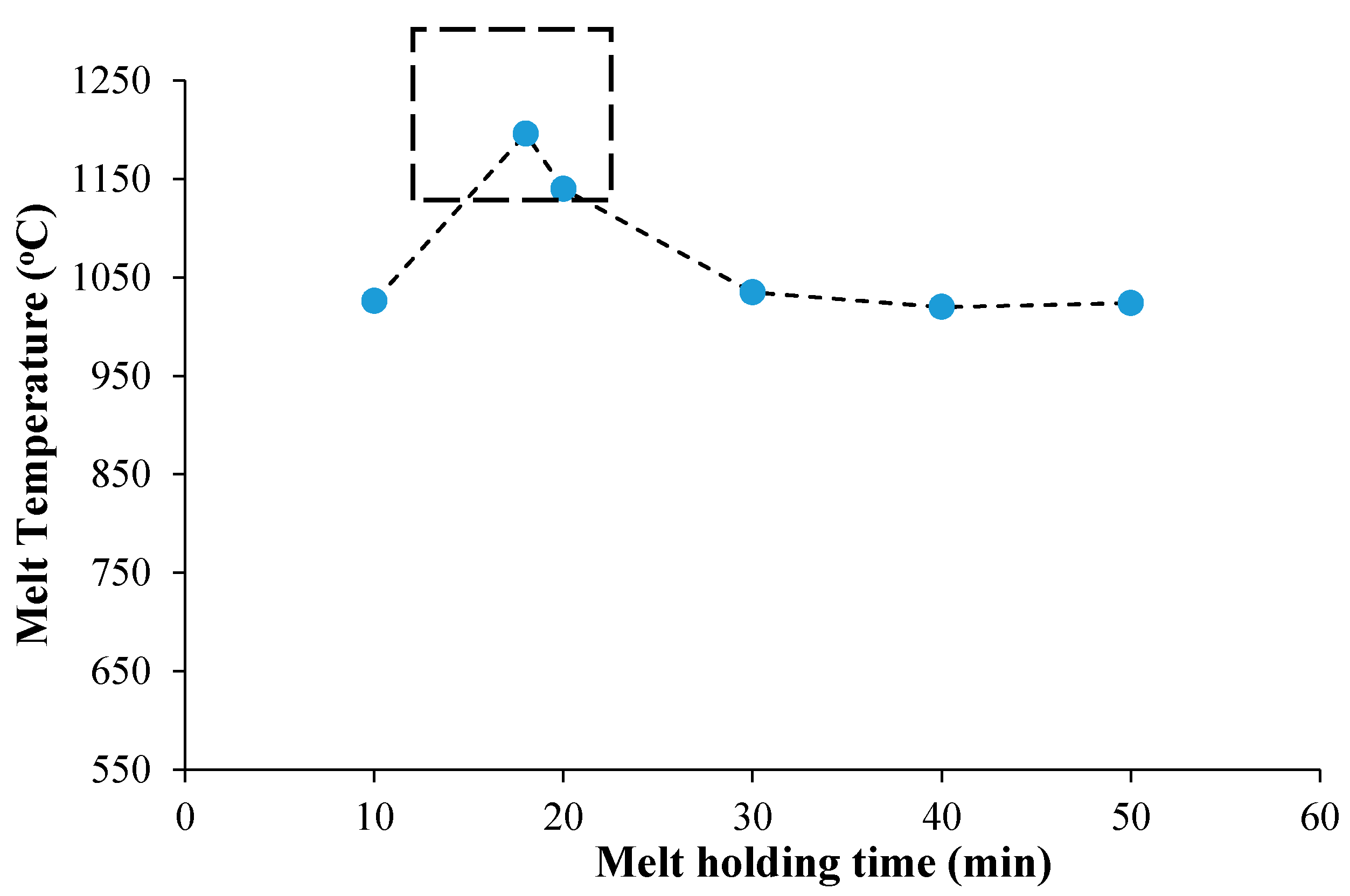
Flux-assisted synthesis (FAS) for fabrication of composite was carried out by liquid metallurgy route. After adding required proportions of halide fluxes in pre-melted aluminium above 1000 °C, the melt was held for 10 min to 50 min, and the temperature was monitored. The reaction between fluxes and molten aluminium increases melt temperature as shown in Figure 1. It was observed that the melt temperature shoots up at ~18 min of holding time (first measured at 10 min and 20 min, predicted and afterward confirmed at 18 min) in most cases. There is a steady decrease in melt temperature after 18 min because the heat was not generated afterward as the exothermic reaction between fluxes and aluminium was completed. The exothermic reaction in molten aluminium was also reported elsewhere by observational temperature rise during DSC analysis of flux-assisted synthesis of TiB2 in aluminium [20].
3.2. Formation and Distribution of TiB2 Phases
In Reference [19], it was found that particles of the in situ formed TiB2 are ultrafine and their size is less than 1 μm [19]. In the present work, aluminium metal matrix composite’s composition is superimposed to locate the possible phases in the proposed Ternary alloy as shown in Figure 2.
It is clear that the proposed composite essentially consists of Al and TiB2 only. However, in reality, the situation differs due to the effect of variation in holding time, precipitation mechanism and stable/unstable phases. The optical microscopy of Al-MMCs, as revealed in Figure 3, shows clusters of TiB2 in the matrix phase. There is minimal change in grain size due to change in a hold time of melt [19]. However, clusters of TiB2 in any cases are widely distributed in the matrix of aluminium. The area fraction of clusters observed in 2.5% is less than to that in 5%TiB2 added reinforcements in the matrix. This confirms alike precipitation of particles through flux-assisted synthesis. Morphology of clusters is not identified to a particular shape. Dispersion of clusters in the matrix is not uniform for a different holding time. Despite having electromagnetic stirring effect in the induction furnace, it may be noted that the tendency of clustering goes up with increasing holding time particularly after 20 min in Al-2.5%TiB2 as well as Al-5%TiB2 composites. This behavior of clustering is due to ultrafine TiB2 particles as a result of reducing surface energy [1].
It is observed that besides precipitation of TiB2, there is a formation of intermediate phase (Ti3B4) as evident in Figure 4. The holding time of 10 min does not seem to be adequate to allow precipitation of TiB2 despite the presence of allied reaction products like AlB2 and Al3Ti. These intermetallic compounds are unstable and according to Reaction (2) result in the formation of TiB2 in molten aluminium.
However, holding time of 20 min is sufficient for precipitation of TiB2, and hence no evidence of other allied phases was noted. However, a higher holding time of 50 min is primarily dominated by Ti3B4. It means higher holding time of liquid processing affects precipitation of TiB2. This is because of increasing volume of cryolite slag having reaction byproducts 3KAlF4, K3AlF6 and Al2O3. Formation of alumina (Al2O3) in the slag disturbs the desired Al-B-Ti (Al: 94 at %, Ti: 1.9 at %, B: 3.8 at %) atomic ratio. It is also responsible for disturbing the stoichiometric ratio of Ti and B. In other words, precipitation of respective phases are decided by the certain ratio of Ti to B. Normally, it is essential to have Ti:B ratio of 0.5:1, 1:1 and 0.75:1 for TiB2, TiB and Ti3B4, respectively. The formation of Ti3B4 could be due to loss of boron by oxidation because free energy of B2O3 formation is more negative than TiO2 [13,21].
Magnified images by SEM of the clustered region of fabricated composite shown in Figure 5 indicates segregation of TiB2 particles of size 1–2 μm. These microscopic precipitates of TiB2 formed during liquid melt processing exhibit high surface energy and are tending to segregate under the influence of convective current produced in an induction furnace. Ti3B4 is visible with distinct morphology as shown in Figure 5b,d and it has numerous small protrusions on the surface of the Ti3B4 precipitate. As holding time changes, not only the distribution but also the stability of TiB2 phase changes which results in growth of Ti3B4 platelets [22]. If melt is maintained above 1000 °C, small and inefficacious Ti3B4 platelets are nucleated via reactions Ti + TiB2 ≥ Ti3B4 (small platelets) and 2TiB + TiB2 ≥ Ti3B4 (big platelets) as seen in Figure 5b,d.
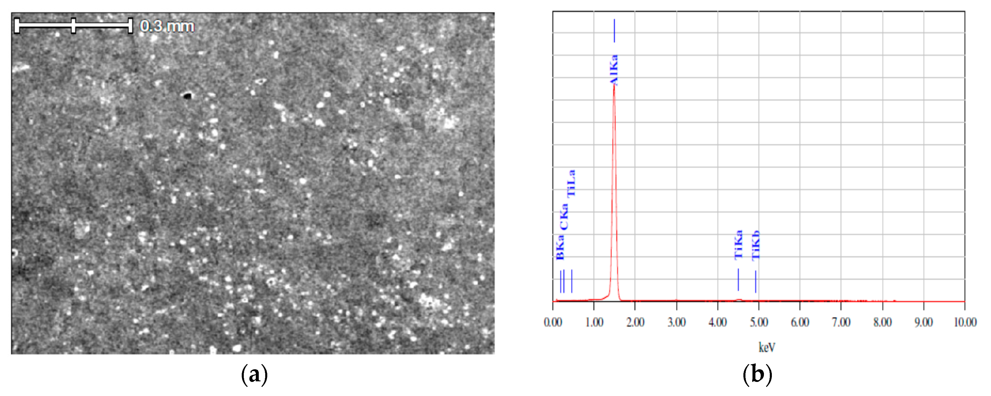
Figure 6b gives EDS spectrum of Al-5%TiB2 composite with peaks of aluminium and titanium for semi-quantitative investigation of reinforcing phase as shown in Figure 6a. As the atomic number of B and C is very low, it could not be detected by EDS analysis. The weight percentage of titanium is about 2.33% as given in Table 2, which is acceptable and consistent with the weight percentage of TiB2 (5 wt %).
3.3. Strengthening of the Composite by TiB2 Reinforcement
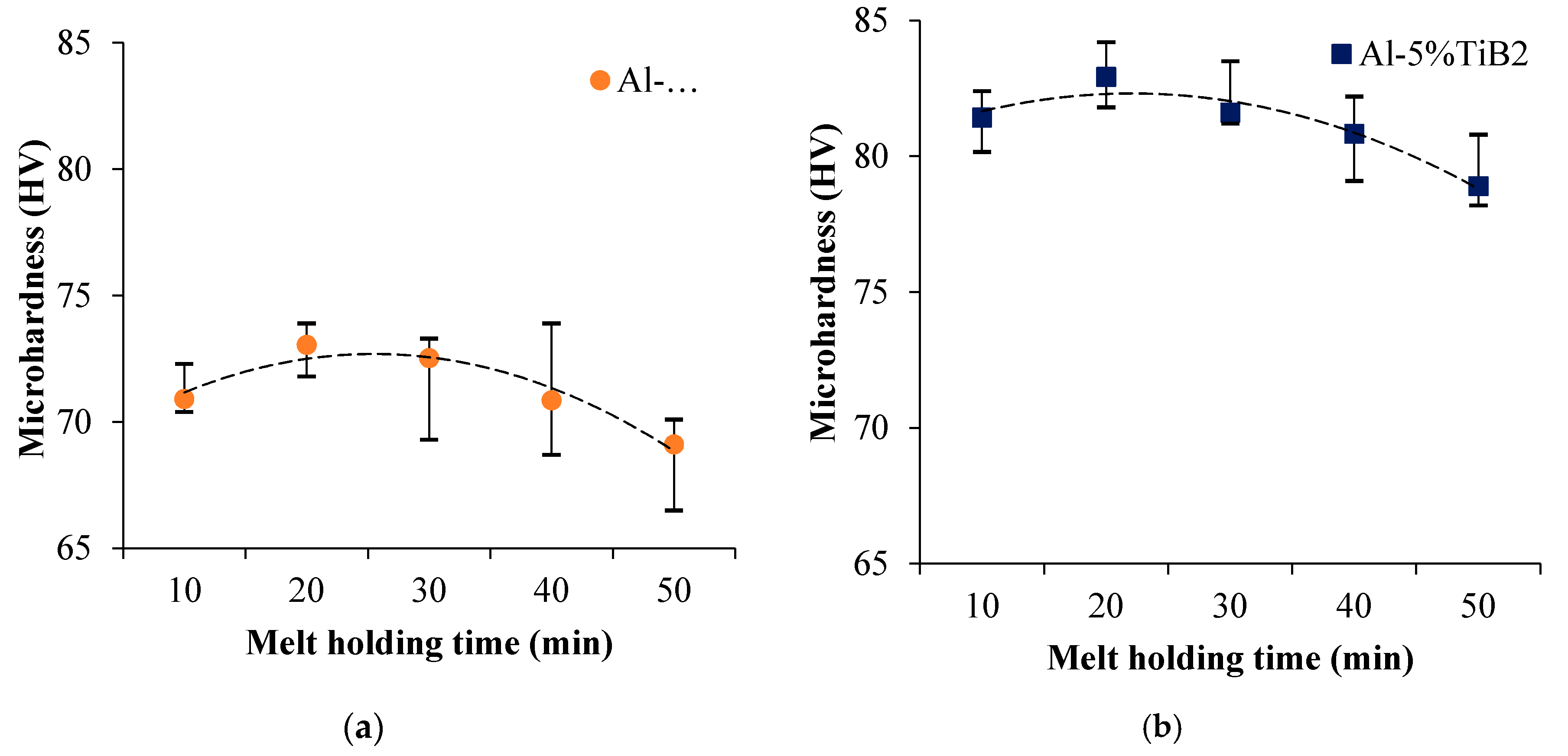
The microhardness for composite is plotted as a function of holding time of melt as shown in Figure 7. The variation in microhardness of composite due to TiB2 reinforcement cluster is recognised in the aluminium matrix. The increase in microhardness with wt % TiB2 attributed to precipitation of phases of Ti and B as compared to pure aluminium. The maximum microhardness seen at 20 min gives a clear indication that TiB2 phase is completely formed and evenly distributed. Lawrance et al. reported optimum holding time of 30 min gives high hardness when similar composite was synthesized by the stir-casting route [23]. On increasing holding time, the distribution of reinforcements gets uneven (as seen from Figure 3) resulting in more deviation of microhardness.
Secondly, a higher holding time of 50 min dominates unnecessary phase Ti3B4 with a concurrent decrease in TiB2 content. It may be seen that increase in microhardness is primarily due to precipitation of TiB2 rather than Ti3B4. Therefore, strengthening of the matrix is mainly by precipitation of TiB2 and to some extent by grain refinement of the aluminium matrix due to Ti and B [24,25].
The variation of wear rates for different holding times of melt is plotted in Figure 8. Each point in the Figure 8 represents the data means, fitted by a General Linear Regression model with a standard error of 0.088. The minimum wear rate is seen at 20 min of holding time, which can be supported by the maximum microhardness (Figure 6) and formation of clusters of TiB2 (Figure 3a). However, the unusual increase in wear rate is seen in composite with an increase of holding time. It is also noticed that wear loss increased with holding time and follows the above said dominance of unnecessary phases like Ti3B4 when melt was held for prolonged times at melt temperature. It may be noted that overall improvement in microhardness or wear resistance is obtained mainly by TiB2 [26]. The reinforcing phase (TiB2) is an essential load-bearing element in the matrix which facilitates the transfer of load.
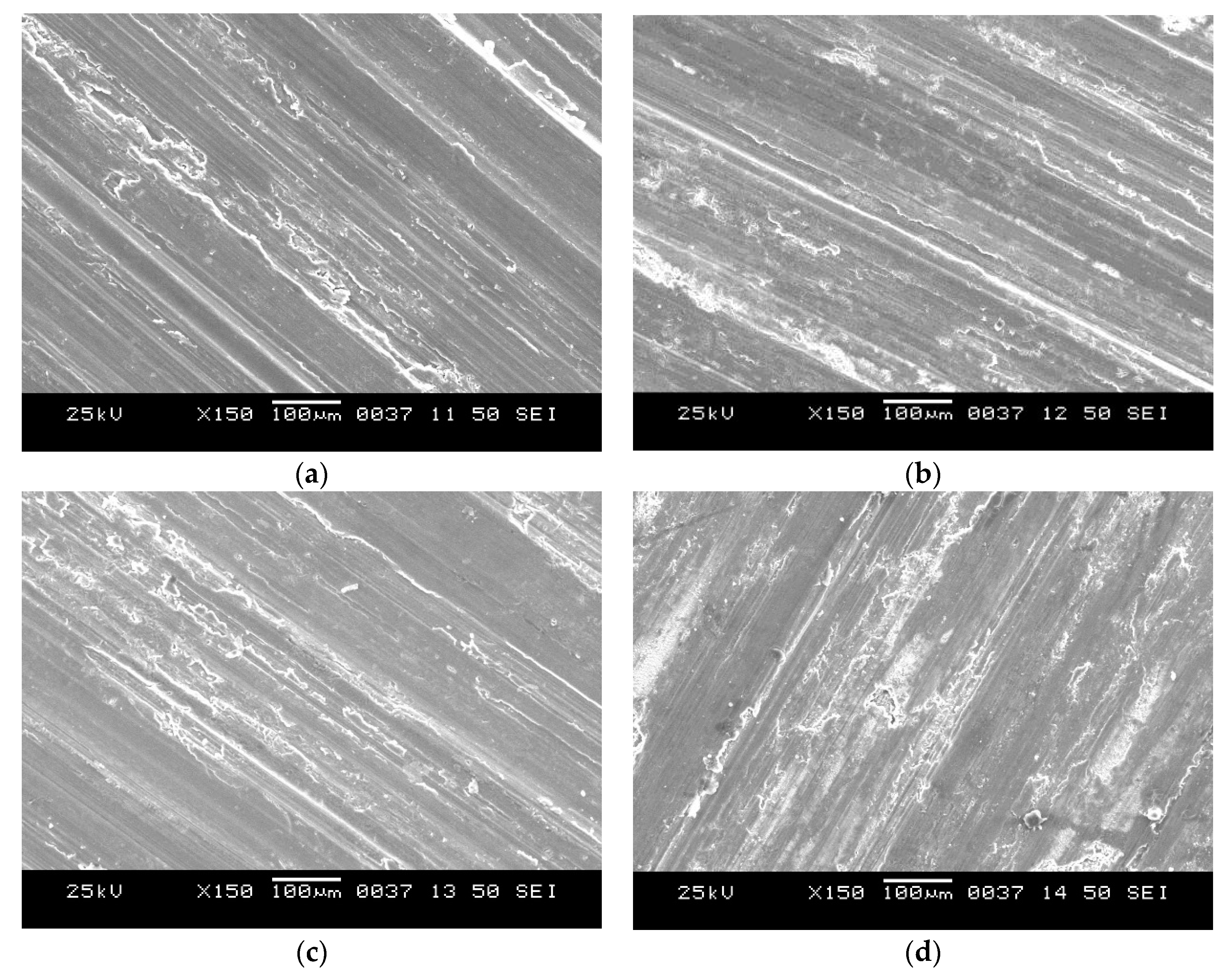
The shift in wear mode from mild delamination to severe delamination is well identified at 20 min of holding time. The overall wear particle formation in such a particulate composite also follows the Suh theory [27]. Mild adhesive wear mode is shown in Figure 9a,c, and severe delamination wear mode is dominated at higher holding time of liquid metal as evident in Figure 9b,d. Increasing reinforcement volume improves the mean microhardness of composite; however number of wear particles also increased (abrasive wear mode) which is undesirable for tribological applications. In summary, Al-5 wt % TiB2 composite with 20 min of holding time has an optimal combination of mechanical strength and wear resistance.
4. Conclusions
Based on the analysis of the mechanical properties and wear resistance of the synthesized Al-MMCs and optimization of the reinforcement content and holding time of the melt at elevated temperatures, the following conclusions were drawn.
The microhardness of the Al-5%TiB2 MMC reaches a maximum after 20 min of holding time. After that, the microhardness drops with increasing holding time of the melt because of the simultaneous segregation of TiB2 particles and the formation of the Ti3B4 phase. In a similar manner, the optimal holding time of 20 min is directly related to the minimal wear rate, and improved microhardness for most of the composites considered in this study. The wear mechanism changes from mild wear dominated by TiB2 formation to severe/abrasive mode due to (a) the formation of the Ti3B4 phase with increasing holding time, and (b) clustering of the ultrafine reinforcements with increasing their concentration and holding time. However, these quantified characteristics do not allow us to distinguish individual effects. Due to induction stirring, the optimal holding time for the melt is shorter than that optimized elsewhere for the stir-casting route. This saves a considerable amount of energy, which would have otherwise been needed for maintaining the composite in the molten state.
Author Contributions
K.R. designed and performed the experiments. K.R. and N.D. analyzed the data with equal contribution. K.R. wrote the paper, and he is the corresponding author.
Funding
This research was funded by University Grant Commission, India grant number 88-2010.
Acknowledgments
The authors of this research paper declare that College of Engineering, Pune provided experimental resources for composite fabrications and testing, whereas SEM and XRD facilities of VNIT, Nagpur were used for the analysis.
Conflicts of Interest
The authors declare no conflicts of interest.
References
- Clyne, T.W.; Robert, M.H. Stability of intermetallic aluminides in liquid aluminium and implications for grain refinement. Met. Technol. 1980, 7, 177–185. [Google Scholar] [CrossRef]
- Miracle, D.B. Metal Matrix Composites—From science to technological significance. Compos. Sci. Technol. 2005, 65, 2526–2540. [Google Scholar] [CrossRef]
- Yue, N.L.; Lu, L.; Lai, M.O. Application of thermodynamic calculation in the in-situ process of Al/TiB2. Compos. Struct. 1999, 47, 691–694. [Google Scholar] [CrossRef]
- Sivaprasad, K.; Babu, S.P.K.; Natarajan, S. Study on abrasive and erosive wear behaviour of Al 6063/TiB2 in situ composites. Mater. Sci. Eng. A 2008, 498, 495–500. [Google Scholar] [CrossRef]
- Luo, A. Processing, microstructure and mechanical behavior of cast magnesium metal matrix composites. Met. Mater. Trans. A 1995, 26, 2445–2455. [Google Scholar] [CrossRef]
- Han, Y.; Liu, X.; Bian, X. In situ TiB2 particulate reinforced near eutectic Al-Si alloy composites. Compos. Part A 2002, 33, 439–444. [Google Scholar] [CrossRef]
- Koczak, M.J.; Premkumar, M.K. Emerging technologies for the in situ production of MMCs. JOM 1993, 45, 44–48. [Google Scholar] [CrossRef]
- Tjonga, S.C.; Wub, S.Q.; Zhu, H.G. Wear behavior of in situ TiB2·Al2O3/Al and TiB2·Al2O3/Al-Cu composites. Compos. Sci. Technol. 1999, 59, 1341–1347. [Google Scholar] [CrossRef]
- Shi, L.; Gu, Y.; Chen, L. A convenient solid-state reaction route to nanocrystalline TiB2. Compos. Part A 2005, 36, 1177–1187. [Google Scholar] [CrossRef]
- Wang, F.-C.; Zhang, Z.-H.; Luo, J.; Huang, C.-C.; Lee, S.-K. A novel rapid route for in situ synthesizing TiB–TiB2 composites. Compos. Sci. Technol. 2009, 69, 2682–2687. [Google Scholar] [CrossRef]
- Jha, A.; Dometakis, U.C. The dispersion mechanism of TiB2 ceramic phase in molten aluminium and its alloys. Mater. Des. 1997, 18, 297–301. [Google Scholar] [CrossRef]
- Christy, T.V.; Murugan, N.; Kumar, S. A comparative study on the microstructures and mechanical properties of Al 6061 alloy and the MMC Al 6061/TiB2. J. Miner. Mater. Charact. Eng. 2010, 9, 57–65. [Google Scholar]
- Kennedy, A.R.; Wyatt, S.M. Effect of processing on the mechanical properties and interfacial strength of aluminium TiC MMCs. Compos. Sci. Technol. 2000, 60, 307–314. [Google Scholar] [CrossRef]
- Lu, L.; Lai, M.O.; Su, V.; Teo, H.L. In-situ TiB2 reinforced Al alloy composites. Scr. Mater. 2001, 45, 1017–1023. [Google Scholar] [CrossRef]
- Watson, I.G.; Forster, M.F.; Lee, P.D.; Dashwood, R.J.; Hamilton, R.W.; Chirazi, A. Investigation of the clustering behavior of titanium diboride particles in aluminium. Compos. Part A 2005, 36, 1177–1187. [Google Scholar] [CrossRef]
- Smalcerz, A.; Przylucki, R. Impact of electromagnetic field upon temperature measurement of induction heated charges. Int. J. Thermophys. 2013, 34, 667–679. [Google Scholar] [CrossRef]
- Gagnoud, A.; Leclercq, I. Electromagnetic modelling of induction melting devices in cold crucible. IEEE Trans. Magn. 1988, 24, 573–575. [Google Scholar] [CrossRef]
- Youssef, Y.M.; Dashwood, R.J.; Lee, P.D. Effect of clustering on particle pushing and solidification behavior in TiB2 reinforced aluminium PMMCs. Compos. Part A 2005, 36, 747–763. [Google Scholar] [CrossRef]
- Dhokey, N.B.; Ghule, S.; Rane, K.; Ranade, R.S. Effect of KBF4 and K2TiF6 on precipitation kinetics of TiB2 in aluminium matrix composite. J. Adv. Mater. Lett. 2011, 2, 210–216. [Google Scholar] [CrossRef]
- Raghavan, V. Al-B-Ti (Aluminum-Boron-Titanium), phase diagram evaluations: Section II. J. Phase Equilib. Diffus. 2009, 30, 610–613. [Google Scholar] [CrossRef]
- Ma, X.; Li, C.; Du, Z.; Zang, W. Thermodynamic assessment of the Ti-B system. J. Alloys Compd. 2004, 370, 149–158. [Google Scholar] [CrossRef]
- Brodkin, D.; Zavaliangos, A.; Kalidindi, S.; Barsoum, M. Transient Plastic Phase Processing of Titanium Carbide-Titanium Boride Composites: Reaction Paths and Microstructural Evolution; No. CONF-9409291; OSTI: Oak Ridge, TN, USA, 1994; pp. 58–59. [Google Scholar]
- Lawrance, C.A.; Prabhu, P.S. Al 6061-TiB2 metal matrix composite synthesized with different reaction holding times by in-situ method. Int. J. Compos. Mater. 2015, 5, 97–101. [Google Scholar]
- Murty, B.S.; Kori, S.A.; Venkateswarlu, K.; Bhat, R.R.; Chakraborty, M. Manufacture of Al–Ti–B master alloys by the reaction of complex halide salts with molten aluminium. J. Mater. Process. Technol. 1999, 89–90, 152–158. [Google Scholar] [CrossRef]
- Poria, S.; Sahoo, P.; Sutradhar, G. Tribological characterization of stir-cast aluminium-TiB2 metal matrix composites. Silicon 2016, 8, 591–599. [Google Scholar] [CrossRef]
- Dhokey, N.B.; Rane, K.K. Wear behavior and its correlation with mechanical properties of TiB2 reinforced aluminium-based composites. Adv. Tribol. 2011, 2011. [Google Scholar] [CrossRef]
- Suh, N.P.; Archard, J.F.T. Contact and rubbing of flat surfaces. J. Appl. Phys. 1953, 24, 981–988. [Google Scholar]
Figure 1.
Temperature variation due to exothermicity of reactions during liquid metal processing in induction furnace.
Figure 1.
Temperature variation due to exothermicity of reactions during liquid metal processing in induction furnace.

Figure 2.
Al-B-Ti computed isothermal section at 1000 °C to locate possible microstructural phases in 5%TiB2 Al-MMC (Al: 94 at % (95 wt %), Ti: 1.9 at % (3.44 wt %), B: 3.8 at % (1.55 wt %) [20].
Figure 2.
Al-B-Ti computed isothermal section at 1000 °C to locate possible microstructural phases in 5%TiB2 Al-MMC (Al: 94 at % (95 wt %), Ti: 1.9 at % (3.44 wt %), B: 3.8 at % (1.55 wt %) [20].

Figure 3.
The optical microstructure of Al-2.5%TiB2 for (a) holding time of 20 min, (b) holding time of 50 min and Al-5%TiB2 for (c) holding time of 20 min, (d) holding time of 50 min.
Figure 3.
The optical microstructure of Al-2.5%TiB2 for (a) holding time of 20 min, (b) holding time of 50 min and Al-5%TiB2 for (c) holding time of 20 min, (d) holding time of 50 min.

Figure 4.
X-ray diffraction (XRD) spectrum for Al-5%TiB2 metal matrix composite for various holding time of melt.
Figure 4.
X-ray diffraction (XRD) spectrum for Al-5%TiB2 metal matrix composite for various holding time of melt.

Figure 5.
Magnified image of clusters of (Figure 3) by SEM shows segregation of TiB2 (a,c) for 20 min and particles and Ti3B4 (b,d) for 50 min.
Figure 5.
Magnified image of clusters of (Figure 3) by SEM shows segregation of TiB2 (a,c) for 20 min and particles and Ti3B4 (b,d) for 50 min.

Figure 6.
X-ray spectroscopy (EDS) of cast Al-5%TiB2 sample corresponds to melt holding time of 20 min (a) region of interest for EDS analysis and (b) EDS spectrum.
Figure 6.
X-ray spectroscopy (EDS) of cast Al-5%TiB2 sample corresponds to melt holding time of 20 min (a) region of interest for EDS analysis and (b) EDS spectrum.

Figure 7.
Microhardness variation with holding time for (a) Al-2.5%TiB2 and (b) Al-5%TiB2 composite.
Figure 7.
Microhardness variation with holding time for (a) Al-2.5%TiB2 and (b) Al-5%TiB2 composite.

Figure 8.
Influence of melt holding time on sliding wear rate for different Al-TiB2 composites.

Figure 9.
Worn surfaces of Al-2.5%TiB2 for (a) holding time of 20 min, (b) holding time of 50 min and Al-5%TiB2 for (c) holding time of 20 min, (d) holding time of 50 min.
Figure 9.
Worn surfaces of Al-2.5%TiB2 for (a) holding time of 20 min, (b) holding time of 50 min and Al-5%TiB2 for (c) holding time of 20 min, (d) holding time of 50 min.


Table 1.
Mass balance calculation to obtain 200 g of TiB2 Al-MMC.
| Composite | Reactants | Products | ||||
|---|---|---|---|---|---|---|
| Aluminium | K2TiF6 | KBF4 | 120% KBF4 | Aluminium | TiB2 | |
| Al-2.5%TiB2 | 201.47 | 17.24 | 18.07 | 21.68 | 195 | 5 |
| Al-5%TiB2 | 202.94 | 34.14 | 36.14 | 43.36 | 190 | 10 |
| Al-10%TiB2 | 205.73 | 72.29 | 56.89 | 68.26 | 180 | 20 |
Table 2.
Elemental mapping based on EDS spectrum for cast Al-5%TiB2 sample (melt holding time of 20 min.
Table 2.
Elemental mapping based on EDS spectrum for cast Al-5%TiB2 sample (melt holding time of 20 min.
| Element | (KeV) | Mass% | At% |
|---|---|---|---|
| B | - | - | - |
| C | - | - | - |
| Al | 1.486 | 97.67 | 98.67 |
| Ti | 4.508 | 2.33 | 1.33 |
| Total | - | 100 | 100 |
© 2018 by the authors. Licensee MDPI, Basel, Switzerland. This article is an open access article distributed under the terms and conditions of the Creative Commons Attribution (CC BY) license (http://creativecommons.org/licenses/by/4.0/).
Share and Cite
MDPI and ACS Style
Rane, K.; Dhokey, N. On the Formation and Distribution of In Situ Synthesized TiB2 Reinforcements in Cast Aluminium Matrix Composites. J. Compos. Sci. 2018, 2, 52. https://doi.org/10.3390/jcs2030052
AMA Style
Rane K, Dhokey N. On the Formation and Distribution of In Situ Synthesized TiB2 Reinforcements in Cast Aluminium Matrix Composites. Journal of Composites Science. 2018; 2(3):52. https://doi.org/10.3390/jcs2030052
Chicago/Turabian StyleRane, Kedarnath, and Narendra Dhokey. 2018. "On the Formation and Distribution of In Situ Synthesized TiB2 Reinforcements in Cast Aluminium Matrix Composites" Journal of Composites Science 2, no. 3: 52. https://doi.org/10.3390/jcs2030052