Article

Finite Element Modelling and Validation of Thermomechanical Behaviour for Layered Aluminium Parts Made by Composite Metal Foil Manufacturing

Anglia Ruskin University, Chelmsford, Essex CM1 1SQ, UK
*
Author to whom correspondence should be addressed.
J. Compos. Sci. 2018, 2(4), 68; https://doi.org/10.3390/jcs2040068
Submission received: 7 November 2018 / Revised: 29 November 2018 / Accepted: 10 December 2018 / Published: 12 December 2018

Abstract

:
The paper presents finite element modelling and thermomechanical analysis on the tensile properties of layered aluminium 1050 metal foil parts made by composite metal foil manufacturing. In this paper, a three-dimensional finite element model was developed and validated through experiments to analyse thermal effects on the tensile properties of 200-μm-thick aluminium 1050 metal foils. The effects of thermal stress and strain were studied by carrying out transient thermal analysis on the heated plates used to join the 200-μm-thick metal foils together using a special brazing paste. A standard tensile test at ambient temperature was carried out on the resulting layered dog bone specimens to analyse the thermal effects on the individual layers of metal. The investigations were precisely designed to assess the effect of heat provided amid the brazing operation to join the metal thwarts together as a layered structure and whether it assumed a part in affecting the tensile properties of the final products when contrasted to a solid aluminium 1050 dog bone specimen of the same dimensions. Corrosion testing was also carried out on dog bone specimens made from varying thickness foils (50 μm, 100 μm, and 200 μm) of aluminium 1050 to assess the effect of corrosion on the tensile strength and elongation. The results showed that the specimens did not face the problem of galvanic corrosion of the foil–bond interface. Microstructural analysis was also carried out to analyse the fracture modes of the tested specimens after corrosion testing.

1. Introduction

Additive manufacturing (AM) technologies have made quite a name for themselves in recent years largely due to their capability to produce complex geometries from computer-aided design (CAD) data. A wide variety of commercial AM techniques are currently available that make use of different materials to produce parts [1,2,3,4,5]. AM processes kept evolving with time and started using other materials than the ones initially intended for their use. These advancements have opened new research opportunities, and the manufacturing industries have capitalized on them by continuing the work and proposing new ways to use different materials. The manufacturing industries were always focused on the production of metal parts, and using AM methods gave them new prospects that were not at their disposal while using subtractive and machining techniques. This led to the modification of several AM methods so that they could provide customized, cost-effective, and high-quality metal parts in a timely manner. However, metal AM methods are also limited in terms of the materials that they can use and are being widely researched so that more materials can be added to this list. There are only a handful of AM processes capable of producing metal parts, with direct metal laser sintering (DMLS) and electron beam melting (EBM) being at the top of the commercially available methods. Metal AM methods can be classified based on the energy source they use, the way feedstock is joined, and the type of feedstock (powder, wire, or sheet). There are four broad classifications of the metal AM processes. They include powder bed systems, powder feed systems, wire feed systems, and sheet laminates. As the name suggests, powder bed and powder feed systems make use of metallic powder. These methods have their limitations, especially in terms of the powder cost, and have been widely researched over the years [6,7,8,9]. Wire feed AM is a promising technology and has come into existence majorly due to the high cost of metal powders that are used for powder bed and powder feed systems. The cost of wire feedstock is much less than metallic powder, but the process is not without flaws. Residual stress and distortion from excessive heat input, poor accuracy of the part due to the stair stepping effect, and relatively poor surface finish of the final parts are notable. These systems require careful monitoring of process parameters such as deposition width, layer thicknesses, wire diameter, wire feed rate, and welding speed to achieve correct part dimensions and surface finish [10,11]. The use of metal sheets, on the other hand, adds flexibility to the process, and they are readily available in the market. Laminated object manufacturing (LOM) has been modified to use metal foils, as it previously used paper sheets. The new process was termed metal foil LOM, but it suffers from the staircase effect, distortion, and poor surface quality [12,13]. Ultrasonic consolidation (UC) is another AM technique that has made quite an impact in recent years. UC requires optimization of its parameters and the use of a milling operation to machine the part after joining, which results in the waste of material [14,15]. All the methods have their individual issues, but in general, cost of operation, time for a single build, and surface quality are at the top of the list.
This study clearly indicates that the production of affordable, time-effective, and high-quality metal parts holds great interest for both the academic and industrial sectors. Therefore, the principles of LOM and brazing were integrated together to form a process that is more “additive” in nature, termed composite metal foil manufacturing (CMFM). This process has shown consistent results for the manufacture of metal and metal composite products [16,17,18,19,20]. CMFM offers several advantages over both experimental metal AM methods (e.g., UC and metal foil LOM), such as minimal optimization of process parameters and minimal post processing. These advantages extend to commercial metal AM methods (e.g., DMLS and EBM) as well, because the feedstock (metal foils) is lower in price. DMLS and EBM make use of metallic powder, and depending upon the type of material, the cost varies. The price of the powder is a function of the grain size and required mechanical properties of the final products as well. Such requirements and the recommendation of large companies such as EOS (for DMLS machines) and ARCAM (for EBM machines) to buy their metal powder for their machines to achieve better mechanical properties for the parts increase the cost of the raw material considerably. The process of CMFM can work with a variety of metals and make composites out of them. Even the parts made from the same material are composites of the material and brazing paste. In the current work, aluminium 1050 grade H14 ½ hard temper foils and a special brazing paste were used. The focus of this paper was to analyse the effect of heat that was supplied to the aluminium 1050 layered part being built during the brazing cycle for final joining (Section 3.1) and whether it affected the tensile properties of the part (Section 3.2).
In general, aluminium has good corrosion resistance because of its oxide layer. However, it is important to assess the bond–foil interface, as any corrosion could result in serious issues (Section 3.3). The most common types of aluminium corrosion are galvanic corrosion and pitting. Galvanic corrosion of aluminium occurs when there is contact with a more noble metal, and at the same time, there is an electrolyte between the metals. Therefore, 80% zinc and 20% aluminium brazing paste was carefully chosen for this research, as this alloy has a similar electrode potential to aluminium and would therefore minimise, if not eliminate, galvanic corrosion. For aluminium, pitting is by far the most common type of corrosion. It occurs only in the presence of an electrolyte (either water or moisture) containing dissolved salts, usually chlorides. The corrosion generally shows itself as an extremely small collection of pits that, in the open air, reach a penetration of a minor fraction of the metal’s thickness. Penetration may be greater in water and soil. As the products of corrosion often cover the points of attack, visible pits are rarely evident on aluminium surfaces [21]. Microscopic inspection is the best way to observe pitting of aluminium, and it was utilised to assess the fractured surface of one of the tensile tested parts after corrosion testing (Section 3.4).

2. Experimental Procedure

Four dog bone specimens were produced and tested according to British and international standards. Aluminium 1050 metal block was used to machine one of the specimens. The other three specimens (S1, S2, and S3) were made from 200-μm-thick aluminium foil, 1050 grade with a H14 ½ hard temper, and a special brazing paste that contained 80% zinc and 20% aluminium by weight suspended in a strong flux. It had an operating range between 410 and 470 °C [22]. Because of such high temperatures, it became essential to analyse the effect of heat provided by the heating plates and whether it adversely affected the mechanical integrity of the parts made by CMFM. For that purpose, ANSYS 19.1 was utilised to carry out 3D transient thermal analysis on the dog bone specimens, with the elements of the analysis being shown in Figure 1. An experiment was also conducted by placing two thermocouples on the paste-coated foils sandwiched between two heating plates to record the temperature values. The plates could be operated simultaneously as well as individually. The average temperature values from the experiment were used to undertake static structural analysis to investigate the effect of thermal stress and strain.
Corrosion testing was conducted on dog bone specimens made from different thicknesses (50 μm, 100 μm, and 200 μm) of aluminium 1050 H14 ½ hard temper foils of aluminium 1050 to assess the effect of corrosion on the foil–bond interface. Microstructural analysis was also carried out to investigate the fracture mechanism of the parts made by CMFM and the one machined out of aluminium 1050 block.

2.1. Modelling for Numerical Analysis

Brazing was the joining method employed by CMFM for bonding the metal foils together, and the paste being utilized worked between 410 and 470 °C. Although this temperature was lower than that of the melting temperature for aluminium (660 °C), it lay within the annealing temperature range. Therefore, it was very important to understand its effect on the integrity of the final product. A 3D model was created in ANSYS 19.1 to carry out transient thermal analysis on the 2.9-mm-thick dog bone specimen sandwiched between two stainless steel heated plates. Each plate was 150 mm long, 40 mm wide, and 8 mm thick, and was fitted with three FIREROD cartridge heaters (Watlow, Montana, USA) to allow for uniform heating of the part. The analysis was carried out by setting only one plate at a temperature of 470 °C. The reason for doing that was to allow for a gradual increase in temperature from one end of the product rather than rapid heating from both sides in a small amount of time. Excessive heat could have been detrimental to the product, especially with an overall thickness of only 2.9 mm. Large parts with a thickness over 5 mm should be processed with both plates, but for anything less than 3 mm, it is recommended to use only one plate [23,24]. This simulation was a useful tool and allowed the production of parts in a consistent manner. The material properties for aluminium and the brazing paste are given in Table 1.

2.2. Experiment for Heating Time

Each single layer of aluminium 1050 was 200 μm thick, with an additional layer of brazing paste that was 100 μm in thickness. The overall thickness of the specimen was 2.9 mm (according to British standards discussed in the next section). Two K-type thermocouples with an operating range of −100 °C to 500 °C were wrapped and fixed to the paste-coated layers of foils using heat-resistant Kapton tape, as shown in Figure 2. They were connected to a data logger Datataker DT80 (Datataker Pty Ltd., Melbourne, Australia), and the run time of the experiment was the same as the simulation. The average temperature from the two thermocouples was compared to the temperature obtained from the numerical simulation to validate it. The experimental temperature values were also utilized to assess thermal stress and strain on the dog bone specimen (Section 3.2.1).

2.3. Tensile Test for Dog Bone Specimens

Dog bone specimens were produced and tested according to BS EN ISO 6892-1:2009 [25]. All the specimens (CMFM parts and machined aluminium part) were tested at ambient temperature. They were 2.9 mm thick, 87.5 mm long, 12.5 mm wide, and had a gauge length of 50 mm (Figure 3). The composite specimens (produced by CMFM) consisted of 10 200-μm-thick aluminium foils and 9 100-μm-thick paste layers stacked alternatively on each other. The tensile test was carried out on an INSTRON 5582 testing machine at a crosshead speed of 5 mm/min.

2.4. Corrosion Test of Dog Bone Specimens

The corrosion test was performed in accordance with BS EN ISO 11130:2010 [26]. The aluminium 1050 samples, made from foils of varying thicknesses (50 μm, 100 μm, and 200 μm) while keeping the overall thickness to a maximum of 2.7 mm (to accommodate all the different thicknesses), were immersed in a solution of 35 g of sodium chloride dissolved in 1 liter of distilled water for 24 h. Afterwards, they were dried for 24 h and then tested on the INSTRON 5582 testing machine at a crosshead speed of 5 mm/min according to BS EN ISO 6892-1:2009.

2.5. Microstructural Analysis

The reason for carrying out the microstructural analysis was to study the fracture modes of the tested specimens after the corrosion testing. The thermal properties of materials have always been an interesting topic of research, but in this case the presence of a composite made the study even more complex. There were two different types of materials, aluminium metal foil that stayed in its original state of solid and brazing paste that changed state due to heating. This analysis helped to investigate if there was a difference in the microstructure of the fractured surfaces of the layered specimens after they had gone through corrosion testing.

3. Results and Discussions

3.1. Distribution of Temperature

Transient thermal analysis showed the temperature distribution on the heated plates and the 2.9-mm-thick composite dog bone specimen (Figure 4). It also helped in building parts in an appropriate amount of time rather than overheating them. A balance was required between heating time and temperature, and an oversight could have led to some deleterious results, such as:
  • The flux in the paste could have burned off, and it would not have been able to make a strong bond;
  • Overheating would have resulted in pitting of the foils and increased thermal stress, as well as strain; and
  • A change in material properties could have made the products useless for any engineering application.
The bottom plate was set to a temperature value of 470 °C, and the top plate was at room temperature (20 °C). Figure 5 shows the distribution of temperature on the plate that was set at room temperature after 40 s. As is evident, the temperature was higher in the middle as compared to the sides, because the specimen to be heated was placed there and the transfer of heat was through conduction, which is a faster mode of heat transfer. The reason for running the simulation for 40 s was that after about 20 s, the temperature reached 410 °C, at which the operating range for the brazing paste began (410–470 °C). Since bond integrity is a function of the processing time, therefore, to ensure a strong bond, a shorter brazing cycle with fast heat-up and a very short holding time at maximum temperature was utilized [27]. This left 20 s, after which the maximum temperature on the dog bone specimen sandwiched between the plates reached 435 °C. This was also the recommendation from the paste manufacturer (that within the operating range, the holding time should be around 10–20 s). This numerical simulation has been validated by an experiment that ran for 40 s to assess whether the part could be produced in that time or not. The temperature curve (with respect to time) obtained from this simulation was compared to the one obtained from the experiment as well.

3.2. Validation for Heating Time

The variation of temperature with time (transient) is governed by the following unsteady equation:
1 α T τ = 2 T x 2 + 2 T y 2 + 2 T z 2 + q k .
In Equation (1), α = k ρ c = thermal diffusivity, and q k is the heat source.
In the current scenario, a composite of aluminium and brazing paste was being produced. The equation had to be solved for each layer separately, and then the boundary conditions could be applied. Thermal expansion of the two materials would have also resulted in a different set of conditions. The density and viscosity of the brazing paste had to be incorporated as well. These parameters could be solved analytically, but the thermal contact resistance between the layers was a big issue. When it was introduced, then the analytical solution became significantly more complex. Numerical solutions could, however, be obtained in a relatively simple manner, but such simulations should be validated by experimentation. The numerical simulation described in Section 3.1 formed the basis for the experiment that was run for 40 s. This was the same time as the simulation, and the experiment served as validation to demonstrate the usability of numerical means to produce parts made by CMFM. This eliminated trial and error and allowed for the manufacture of metal parts easily. The 2.9-mm-thick layered dog bone specimen was sandwiched between two stainless steel plates. The bottom plate was set at 470 °C, and it was at the set temperature when the paste-coated foils were placed on it. Two K-type thermocouples were attached to the top of the dog-bone specimen with the help of heat-resistant tape. The thermocouples were connected to a data logger that collected the data for 40 s. The average temperature from the two thermocouples and the temperature taken from the simulation were plotted with respect to time and are shown in Figure 6. It is evident that there was good agreement between the finite element analysis (FEA) and experimental results. This experiment validated the applicability of numerical simulations to produce parts using CMFM. The temperature values obtained from the experiment are used to analyse thermal stress and strain in the same dog bone specimen through numerical means in the next section.

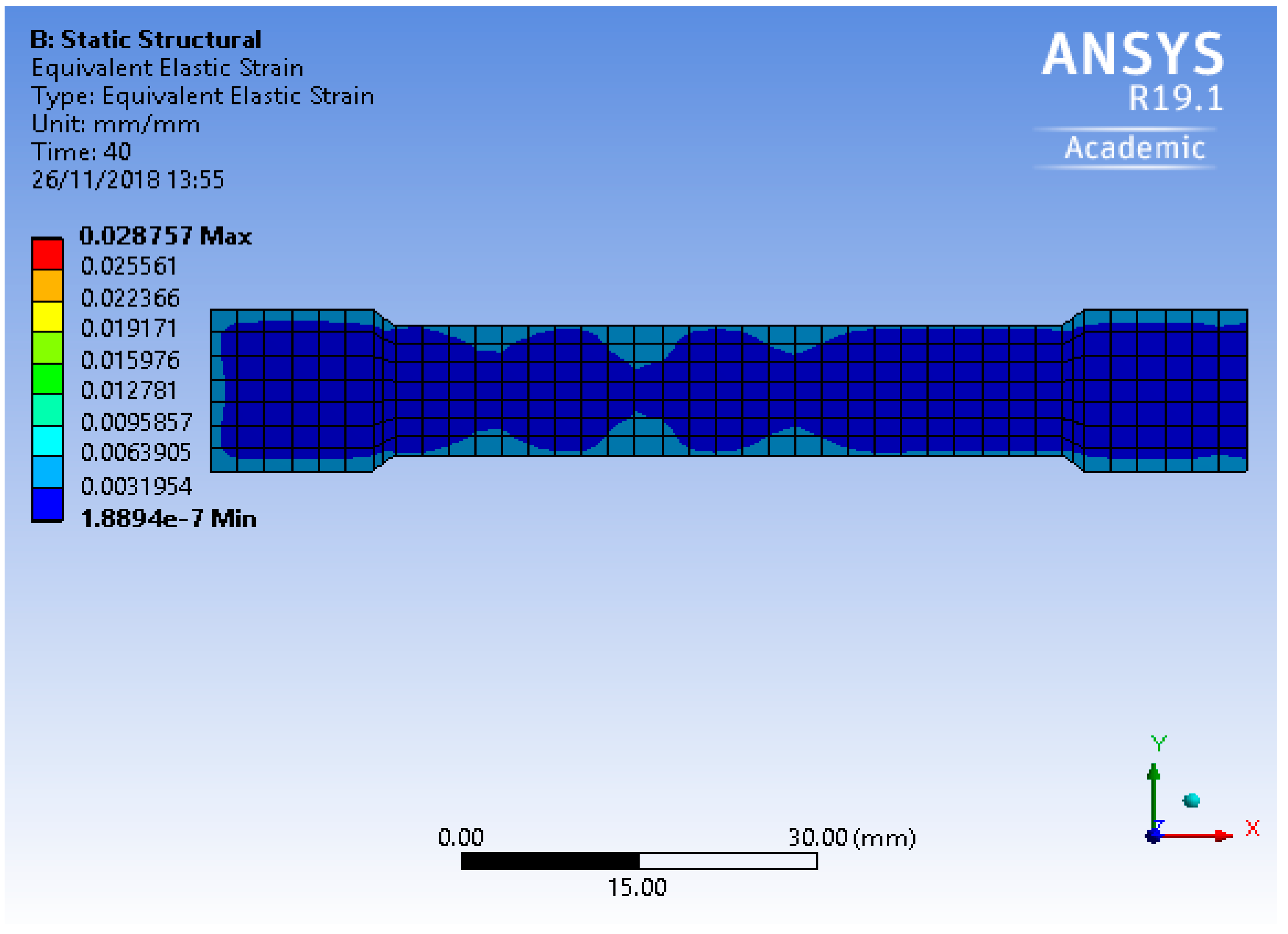
3.2.1 Thermal Stress and Strain

Measuring thermal stress and strain requires the use of expensive and sophisticated equipment, but since the numerical simulation was validated to present good agreement with the experimental results, the temperature values obtained from the thermocouples were used as boundary conditions in the static structural environment of ANSYS 19.1 to analyse thermal stress and strain. In the present case, heat was being transferred from the hot plate (set at 470 °C) by conduction to the paste-coated aluminium foils and was uniform throughout. Due to the continuous contact, the heat was moving from a hot area (heated plate) to a colder area (dog bone specimen) until they were both at the same temperature. Aluminium is a very good conductor of heat, with a thermal conductivity value of 205 W/(m·°C), whereas the brazing paste also has a reasonably good value of 130 W/(m·°C). The temperature data obtained from the heating experiment was used as input for static structural analysis. All the 19 layers (10 aluminium and 9 paste layers) were subjected to varying degrees of temperature with the first layer, which was in contact with the heated plate, reaching and then staying at the maximum temperature value for a longer period compared to the last layer, which was in contact with the plate kept at room temperature.
The focus was on the dog bone specimen, but it was also important to assess the thermal stress and strain on the entire structure (paste-coated aluminium foils sandwiched between two stainless steel plates) to ensure that the appropriate values were being captured. Figure 7 shows the von Mises stress values on the hot plate, with the minimum values being in the centre where the paste-coated layers were placed and the maximum values being at the edges. The strain values in Figure 8 also showed the same picture, with the minimum values being in the middle and the maximum being on the edges of the hot plate. Even though the maximum values were quite high, they did not affect the mechanical integrity of the dog bone specimen because they were far away from the specimen and were localized. The von Mises stress on the top and bottom of the dog bone specimen (without the two stainless steel plates) is shown in Figure 7 and Figure 8. It is interesting to note that the stress was higher on the side adjacent to the cold plate as compared to the hot plate. The reason lay in the metallurgy of the aluminium foil that led to residual stresses. These were the stresses that remained in a solid material after the original cause of the stresses had been removed. In other words, residual stresses in a structural material or component were those stresses that existed in the object without the application of any service or other external loads. There are several causes for the presence of residual stresses in a material. Manufacturing processes are the most common causes of residual stress. Virtually all manufacturing and fabricating processes such as casting, welding, machining, moulding, heat treatment, plastic deformation during bending, rolling, or forging introduce residual stresses into the manufactured object. The manufacturing process for aluminium foil has several steps, including refining, smelting, rolling, and finishing, all capable of inducing residual stresses within the foil. In addition to that, residual stress can be caused by localized yielding of the material, because of a sharp notch, or from certain surface treatments such as shot peening or surface hardening. Among the factors that are known to cause residual stresses are the development of deformation gradients in various sections of the piece by the development of thermal gradients, volumetric changes arising during solidification or from solid state transformations, and from differences in the coefficient of thermal expansion in pieces made from different materials, which was the case here as solid aluminium and brazing paste (that changed phase from semiliquid to liquid and then solid) were being joined together. Thermal residual stresses are primarily due to differential expansion when a metal is heated or cooled. The two factors that control this are thermal treatment (heating or cooling) and restraint. Both the thermal treatment and restraint of the component must be present to generate residual stresses. When any object is formed through cold working, there is the possibility for the development of residual stresses [28]. Figure 9 shows that the von Mises stress on the side of the dog bone specimen adjacent to the hot plate was at the minimum value. This goes to show that the heat treatment during CMFM did not increase the stresses, but rather relieved them in the foil. The reason is the fact that the brazing paste underwent phase transformation from semisolid (original state) to liquid (in its operating range) and to solid (after cooling), and therefore any thermal stress between the layers relaxed. This is evident from the lowest values on the grid. On the other hand, Figure 10 shows that the stress was slightly higher at the edges as they formed areas for stress concentration, but most of the sample was still at the lowest possible values in the grid. In this case, the stresses were relieved, but not to the same extent as the side adjacent to the hot plate, hence the reason for stress concentrations on the edges. This was because the side adjacent to the hot plate stayed at a higher temperature gradient for a longer period. In addition, the annealing temperature of aluminium is around 412 °C [29], which was also responsible for relieving stresses. The same held true for thermal strain due to heat as well. Figure 11 shows the thermal stress for the side adjacent to the hot plate, with values ranging from 1.9 × 10⁻³ to 5.0 × 10⁻³ compared to the higher values ranging from 7.2 × 10⁻³ to 2.6 × 10⁻², with the edges showing the maximum strain for the side of the specimen adjacent to the cold plate (Figure 12). The reason is again the relaxation of the material due to the application of heat that resulted in lower strain values for the side of the specimen subjected to more heat for a longer period.

3.3. Results from the Tensile Test of the Dog-Bone Specimens

The numerical simulation showed 40 s for the manufacture of a 2.9-mm-thick dog bone specimen for tensile testing. This time was validated by the manufacture of the specimen in 40 s. Three dog bone specimens were manufactured for tensile testing after the experimental validation. Generally, tensile testing is routinely practiced and does not involve a high number of precautions, but because parts made by CMFM are composites, it became important to take every factor into account. Such factors included the gauge length of the specimen, the rate of loading, the capacity of the machine, clamping issues, the effect of humidity, and temperature. The gauge length was kept at 50 mm according to the standard (BS EN ISO 6892-1:2009), and the rate of loading was 5 mm/min to allow for a slow application of tensile force to obtain a smooth curve as an output. A 5 kN load cell was used with the INSTRON 5582 (Norwood, MA, USA), which could record the fracture loads of the tested specimens. Proper clamping is very important, which is why wedge action grips were used. As the axial load increased, the wedge acted to increase the squeezing pressure applied to the specimen. The test was carried out at ambient temperature and humidity according to the standard. The force versus displacement curves for the specimens are shown in Figure 13. The Al 1050 specimen made by machining fractured at a load value of 4.483 kN, whereas the parts made by CMFM using 200-μm-thick aluminium 1050 foils fractured at much higher values (S1 = 4.754 kN, S2 = 4.745 kN, and S3 = 4.763 kN). The increase in the fracture value for the CMFM specimens was approximately 6% compared to the parent metal, and they showed good consistency as well. It was already established in Section 3.2.1 that residual stresses did not play a negative part and did not affect the mechanical integrity of the parts made by CMFM. This, coupled with the higher fracture load values from the tensile test, show that the heat added to the foils during the joining operation (brazing) made them stronger due to the chemical reactions taking place between the foil and the paste. Furthermore, it should be noted that aluminium followed its characteristic curve, with a prominent elastic and plastic region. The CMFM parts, on the other hand, had a very small plastic region but had high fracture load values. Aluminium is a ductile material and underwent plastic deformation before fracturing, but the parts made by CMFM were brittle and did not undergo a large plastic deformation before fracturing. The fracture modes of the tested specimens are shown in Figure 14.

3.4. Results from Corrosion Test of Dog Bone Specimens

Galvanic corrosion is a major concern with aluminium, and any corrosion in the bond–foil interface would have seriously undermined the strength of the dog bone specimens. This test was performed to assess the effect of corrosion on the tensile strength and elongation of the specimens made by CMFM. The composite aluminium dog bone specimens were put in a cylindrical container for 24 h. There were three specimens, the first made from aluminium 1050 foils of 50 μm in thickness, the second made from 100-μm-thick foils, and the third made from 200-μm-thick foils. At any given time, only one specimen was immersed in the distilled water and NaCl solution. The pH of the solution was checked using pH strips when the specimen was put in the container and when it was taken out. The value was 7.0 in both cases, which was in the acceptable range. Afterwards, the dog bone specimens were tested on the tensile testing machine at a speed of 5 mm/min and yielded a similar fracture mode (Figure 15) as previously tested specimens (Section 3.3) that had not been tested for corrosion. In our previous work [30], dog bone specimens made from foils of varying thickness were tensile tested as-built, and a comparison between those tests and the ones performed after corrosion testing (Figure 16) is shown in Table 2. The upper half of the table shows the results from our previous work [30], whereas the lower half shows the tensile test results performed after corrosion testing. The fracture loads, ultimate tensile strength (UTS), and elongation values were quite similar. The positive value in Table 2 indicates that the UTS was greater after corrosion testing, whereas the negative values indicate that it was smaller. Good consistency was observed for the tests done under different conditions, which shows the efficiency of the CMFM process. The results clearly indicate that the bond–foil interface for parts made by aluminium 1050 foils and brazing paste did not suffer from galvanic corrosion, which is also backed up by our previous tests on T-peel aluminium specimens [21].

3.5. Results from Microstructural Analysis

The aim of this test was to analyse the microstructure of the fractured surfaces that had undergone corrosion testing. It was established in Section 3.3 that the bond–foil interface was not affected by corrosion, and therefore the microstructure of the parts made by CMFM did not differ very much from the parent aluminium. The difference was along the lines that parent aluminium is ductile, whereas composites made by CMFM are brittle in nature. Aluminium showed inclusions that acted as tiny stress concentrations, as can be seen in Figure 17. They either fractured or separated from the matrix, nucleating voids that grew and linked up, ultimately causing fracture.
The fractured surface in Figure 18 shows the dog bone specimen made from 200-μm-thick foils. It was tensile tested after immersion in distilled water and NaCl solution to assess corrosion damage. It clearly shows the aluminium foil between two layers of brazing paste (Figure 18a). The inclusions that were seen in the case of solid aluminium are still visible in Figure 18b, but not to the same extent [31,32]. The paste made an intermetallic bond with the metal, and the result was a high-strength product that had better tensile properties compared to the parent metal and did not suffer from the issues of galvanic corrosion.

4. Conclusions

This paper presented a 3D finite element model that demonstrated the effect of heat supplied to the specimens during the brazing operation. The temperature readings from the numerical model were validated by running an experiment that involved recording the average temperature values from two thermocouples attached to the specimen as it was being heated to be joined. The two temperature curves (FEA and experimental) showed good agreement, indicating that numerical means could be utilized to assess the time required to produce parts using the process of CMFM. This will prove to be very helpful in producing parts with different thicknesses and geometries. The data obtained from the experiment was used as input to investigate thermal stress and strain induced in the final product as a result of the heat applied during brazing. The analysis showed lower values of thermal stress and strain on the face of the dog bone specimen facing the hot plate, due to residual stresses being relieved as the annealing temperature of aluminium was reached during the brazing operation. This shows that heat provided during the process of CMFM did not adversely affect the product. It was investigated further by undertaking a tensile test. Four dog bone specimens (one from aluminium 1050 block and three from CMFM) were made and tested according to British and international standards. The tensile test at ambient temperature showed that the parts made by CMFM fractured at load values that were approximately 6% higher than that of the parent aluminium, demonstrating that the heat applied during brazing increased the tensile strength of the part due to work hardening.
Galvanic corrosion is a problem with aluminium parts, and any issues with the bond–foil interface would have negatively affected the strength. Hence, three dog bone specimens made from foils of various thicknesses (50 μm, 100 μm, and 200 μm) were immersed in a solution of distilled water and NaCl for 24 h and then tensile tested. The results were compared to previous work that showed equivalent ultimate tensile strength and elongation values, showing that the parts made by CMFM did not suffer from galvanic corrosion. Microstructural analysis showed the presence of voids and inclusions, but to a lesser extent due to the brittle nature of the parts made by CMFM.

Author Contributions

J.B. conceptualized the idea, defined the methodology, conducted the experiments and wrote the first draft of the manuscript; M.G. and A.A. worked on the finite element analysis; H.S. worked on the validation as well as manuscript review and editing.

Funding

This research did not receive any external funding.

Conflicts of Interest

The authors declare no conflict of interest.

References

  1. Yoozbashizadeh, M.; Yavari, P.; Khoshnevis, B. Novel method for additive manufacturing of metal-matrix composite by thermal decomposition of salts. Addit. Manuf. 2018, 24, 173–182. [Google Scholar] [CrossRef]
  2. Tang, S.H.; Cheng, C.W.; Yeh, R.Y.; Hsu, R.Q. Direct joining of 3D-printed thermoplastic parts to SLM-fabricated metal cellular structures by ultrasonic welding. Int. J. Adv. Manuf. Technol. 2018, 99, 729–736. [Google Scholar] [CrossRef]
  3. Kuo, Y.L.; Horikawa, S.; Kakehi, K. Effects of build direction and heat treatment on creep properties of Ni-base superalloy built up by additive manufacturing. Scr. Mater. 2017, 129, 74–78. [Google Scholar] [CrossRef]
  4. Levy, A.; Miriyev, A.; Elliott, A.; Babu, S.S.; Frage, N. Additive manufacturing of complex-shaped graded TiC/steel composites. Mater. Des. 2017, 118, 198–203. [Google Scholar] [CrossRef]
  5. Butt, J.; Shirvani, H. Experimental analysis of metal/plastic composites made by a new hybrid method. Addit. Manuf. 2018, 22, 216–222. [Google Scholar] [CrossRef]
  6. Kazantseva, N.; Krakhmalev, P.; Yadroitsev, I.; Fefelov, A.; Merkushev, A.; Ilyinikh, M.; Vinogradova, N.; Ezhov, I.; Kurennykh, T. Oxygen and nitrogen concentrations in the Ti-6Al-4V alloy manufactured by direct metal laser sintering (DMLS) process. Mater. Lett. 2017, 209, 311–314. [Google Scholar] [CrossRef]
  7. Hadadzadeh, A.; Baxter, C.; Amirkhiz, B.S.; Mohammadi, M. Strengthening mechanisms in direct metal laser sintered AlSi10Mg: Comparison between virgin and recycled powders. Addit. Manuf. 2018, 23, 108–120. [Google Scholar] [CrossRef]
  8. Liu, Y.J.; Wang, H.L.; Li, S.J.; Wang, S.G.; Wang, W.J.; Hou, W.T.; Hao, Y.L.; Yang, R.; Zhang, L.C. Compressive and fatigue behavior of beta-type titanium porous structures fabricated by electron beam melting. Acta Mater. 2017, 126, 58–66. [Google Scholar] [CrossRef]
  9. Arrieta, E.; Haque, M.; Mireles, J.; Stewart, C.; Carrasco, C.; Wicker, R.B. Mechanical Behavior of Differently Oriented Electron Beam Melting Ti–6Al–4V Components Using Digital Image Correlation. J. Eng. Mater. Technol. 2019, 141, 011004. [Google Scholar] [CrossRef]
  10. Ding, D.; Pan, Z.; Cuiuri, D.; Li, H. Wire-feed additive manufacturing of metal components: Technologies, developments and future interests. Int. J. Adv. Manuf. Technol. 2015, 81, 465–481. [Google Scholar] [CrossRef]
  11. Silva, C.C.; Miranda, E.C.D.; Motta, M.F.; Miranda, H.C.D.; Farias, J.P. Minimization of defects in nickel-based superalloy weld overlay deposited by the GTAW cold wire feed process. Weld. Int. 2016, 30, 443–451. [Google Scholar] [CrossRef]
  12. Prechtl, M.; Otto, A.; Geiger, M. Rapid tooling by laminated object manufacturing of metal foil. Adv. Mater. Res. 2005, 6, 303–312. [Google Scholar] [CrossRef]
  13. Prechtl, M.; Otto, A.; Geiger, M. Laminated Object Manufacturing of Metal Foil—Process Chain and System Technology; Springer: Vienna, Austria, 2005; pp. 597–606. [Google Scholar]
  14. Bournias-Varotsis, A.; Friel, R.J.; Harris, R.A.; Engstrøm, D.S. Ultrasonic Additive Manufacturing as a form-then-bond process for embedding electronic circuitry into a metal matrix. J. Manuf. Process. 2018, 32, 664–675. [Google Scholar] [CrossRef] [Green Version]
  15. Mekid, S.; Daraghma, H. Experimental ultrasonic sub-surface consolidation of fiber bragg grating for sensorial materials. J. Mater. Process. Technol. 2018, 252, 673–679. [Google Scholar] [CrossRef]
  16. Butt, J.; Mebrahtu, H.; Shirvani, H. Microstructure and mechanical properties of dissimilar 1050 aluminium/pure copper foil composites made with a new additive manufacturing process. J. Mater. Process. Technol. 2016, 238, 96–107. [Google Scholar] [CrossRef]
  17. Butt, J.; Mebrahtu, H.; Shirvani, H. Rapid prototyping by heat diffusion of metal foil and related mechanical testing. Int. J. Adv. Manuf. Technol. 2016, 84, 2357–2366. [Google Scholar] [CrossRef]
  18. Butt, J.; Mebrahtu, H.; Shirvani, H. A novel rapid prototyping process for the production of metal parts. In Proceedings of the Second International Conference on Advances in Civil, Structural and Mechanical Engineering-CSM, Birmingham, UK, 16–17 November 2014; pp. 26–29. [Google Scholar]
  19. Butt, J. A Novel Additive Manufacturing Process for the Production of Metal Parts. Doctoral Dissertation, Anglia Ruskin University, Cambridge, UK, 2016. [Google Scholar]
  20. Butt, J.; Mebrahtu, H.; Shirvani, H. Tensile lap-shear and flexural behaviour of aluminium metal foil parts made by composite metal foil manufacturing. Prog. Addit. Manuf. 2018, 1–9. [Google Scholar] [CrossRef]
  21. Butt, J.; Mebrahtu, H.; Shirvani, H. Peel and tensile test investigation of aluminium 1050 foil parts made with a new additive manufacturing process. Int. J. Rapid Manuf. 2015, 5, 95–115. [Google Scholar] [CrossRef]
  22. Butt, J.; Mebrahtu, H.; Shirvani, H. Numerical and experimental analysis of product development by composite metal foil manufacturing. Int. J. Rapid Manuf. 2018, 7, 59–82. [Google Scholar] [CrossRef]
  23. Butt, J.; Mebrahtu, H.; Shirvani, H. Thermo-Mechanical Analysis of Dissimilar Al/Cu Foil Single Lap Joints Made by Composite Metal Foil Manufacturing. World Acad. Sci. Eng. Technol. Int. J. Mech. Aerosp. Ind. Mechatron. Manuf. Eng. 2015, 10, 41–46. [Google Scholar]
  24. Nammi, S.K.; Butt, J.; Mauricette, J.L.; Shirvani, H. December. Numerical Analysis of Thermal Stresses around Fasteners in Composite Metal Foils. In IOP Conference Series: Materials Science and Engineering; IOP Publishing: Bristol, UK, 2017; Volume 280, p. 012016. [Google Scholar]
  25. BS EN ISO 6892-1:2009. Metallic Materials. Tensile Testing. Method of Test at Ambient Temperature; British, European and International Standard: London, UK, 2009. [Google Scholar]
  26. BS EN ISO 11130:2010. Corrosion of Metals and Alloys—Alternate Immersion Test in Salt Solution; British, European and International Standard: London, UK, 2010. [Google Scholar]
  27. Murakami, T.; Nakata, K.; Tong, H.; Ushio, M. Dissimilar metal joining of aluminum to steel by MIG arc brazing using flux cored wire. ISIJ Int. 2003, 43, 1596–1602. [Google Scholar] [CrossRef]
  28. Fratini, L.; Zuccarello, B. An analysis of through-thickness residual stresses in aluminium FSW butt joints. Int. J. Mach. Tools Manuf. 2006, 46, 611–619. [Google Scholar] [CrossRef]
  29. Qiao, X.G.; Starink, M.J.; Gao, N. Hardness inhomogeneity and local strengthening mechanisms of an Al1050 aluminium alloy after one pass of equal channel angular pressing. Mater. Sci. Eng. A 2009, 513, 52–58. [Google Scholar] [CrossRef] [Green Version]
  30. Butt, J.; Mebrahtu, H.; Shirvani, H. Strength analysis of aluminium foil parts made by composite metal foil manufacturing. Prog. Addit. Manuf. 2016, 1, 93–103. [Google Scholar] [CrossRef] [Green Version]
  31. Butt, J.; Mebrahtu, H.; Shirvani, H. Metal Rapid Prototyping Technologies. In Advances in Engineering Research; Petrova, V.M., Ed.; Nova Science Publishers, Inc.: New York, NY, USA, 2017; Volume 14, Chapter 2; pp. 13–52. [Google Scholar]
  32. Butt, J.; Shirvani, H. Additive, Subtractive, and Hybrid Manufacturing Processes. In Advances in Manufacturing and Processing of Materials and Structures; CRC Press: Boca Raton, FL, USA, 2018; pp. 187–218. [Google Scholar]
Figure 1. Elements of transient thermal analysis.
Jcs 02 00068 g001
Figure 2. Experimental setup for heating time.
Jcs 02 00068 g002
Figure 3. Dimensions of dog bone specimens.
Jcs 02 00068 g003
Figure 4. Temperature distribution on the plates and the dog bone specimens.
Jcs 02 00068 g004
Figure 5. Temperature distribution of the OFF plate.
Jcs 02 00068 g005
Figure 6. Comparison between finite element analysis and experimental results.
Jcs 02 00068 g006
Figure 7. Hot plate showing thermal stress.
Jcs 02 00068 g007
Figure 8. Hot plate showing thermal strain.
Jcs 02 00068 g008
Figure 9. Thermal stress on the foil adjacent to the hot plate.
Jcs 02 00068 g009
Figure 10. Thermal stress on the foil adjacent to the cold plate.
Jcs 02 00068 g010
Figure 11. Thermal strain on the foil adjacent to the hot plate.
Jcs 02 00068 g011
Figure 12. Thermal strain on the foil adjacent to the cold plate.
Jcs 02 00068 g012
Figure 13. Comparative tensile test between Al 1050 and composite metal foil manufacturing (CMFM) specimens.
Jcs 02 00068 g013
Figure 14. Fracture modes: (a) Al 1050; (b) CMFM specimen.
Jcs 02 00068 g014
Figure 15. Fractured CMFM specimen tensile tested after being immersed in distilled water and NaCl solution.
Jcs 02 00068 g015
Figure 16. Comparative tensile test for foils of different thicknesses.
Jcs 02 00068 g016
Figure 17. SEM analysis of 1050 aluminium at 1000×.
Jcs 02 00068 g017
Figure 18. SEM analysis of CMFM part: (a) Fractured foil at 500×; (b) fractured foil at 1000×.
Jcs 02 00068 g018
Table 1. Mechanical and thermal properties of materials.
PropertiesMaterials
Al 1050Brazing Paste
Yield Strength (MPa)105–14545
Tensile Strength (MPa)12060
Young’s Modulus (GPa)6960
Thermal Conductivity (W/(m·°C))205900
Specific Heat (J/(kg·°C))130480
Table 2. Comparative tensile test results before and after corrosion testing.
TestSpecimensFracture Load (kN)Total Elongation (%)Ultimate Tensile Strength (UTS) (MPa)Difference in UTS (%)
Before corrosion testingAl 10504.4821.5132.8Compared to Al 1050
0.05 mm4.922.6145.89.8
0.1 mm4.852.8143.88.3
0.2 mm4.753.1140.86.0
Compared to corresponding foil parts
After corrosion testing0.05 mm4.92.5145.2−0.4
0.1 mm4.882.6144.6+0.5
0.2 mm4.712.8139.5−0.9

