Axial Compressive Stress-Strain Model Developed for FRP-Confined Concrete Columns with Elliptical Cross Sections


School of Civil Engineering, Harbin Institute of Technology, Harbin 150090, China
*
Author to whom correspondence should be addressed.
J. Compos. Sci. 2018, 2(4), 67; https://doi.org/10.3390/jcs2040067
Submission received: 4 October 2018
/
Revised: 20 November 2018
/
Accepted: 21 November 2018
/
Published: 27 November 2018
(This article belongs to the Special Issue FRP Composites in Structural Concrete)
Abstract
:Most existing studies conducted on fiber-reinforced polymer (FRP)-confined concrete have considered circular and square concrete columns, while limited studies have considered columns with rectangular sections. Studies have confirmed that the circular cross-sections exhibited higher confinement effectiveness, whereas in the case of non-circular cross-sections the efficiency of FRP confinement decreases with an increase of the sectional aspect ratio and there is no significant increase, particularly for columns with the aspect ratio of 2.0. As recently suggested by researchers, to significantly increase the effectiveness of FRP-confinement for these columns involves changing a rectangular section into an elliptical or oval section. According to the literature, most of the existing confinement models for FRP-confined concrete under axial compression have been proposed for columns with circular and rectangular cross-sections. However, modeling of the axial strength and strain of concrete confined with FRP in elliptical cross-sections under compression is limited. Therefore, this paper provides new expressions based on limited experimental data available in the literature. For a sufficient amount of FRP-confinement, the threshold value was proposed to be 0.02. Finally, the accuracy of the proposed model was verified by comparing its predictions with the same test database, together with those from the existing models.
1. Introduction
It is widely reported that confinement of existing concrete columns in bridges and buildings using fiber-reinforced polymers (FRPs) can significantly increase the strength and ductility of the columns. Over the last 25 years, a large number of experimental tests and analytical models were focused on the axial compressive behavior of FRP-confined concrete, e.g., [1,2,3,4,5,6,7,8,9,10,11,12,13,14,15,16,17,18,19,20,21,22,23,24,25]. The majority of the existing studies have focused on modeling the stress-strain behavior of FRP-confined concrete in circular cross-sections under axial compression, while only limited studies have considered FRP-confined concrete in rectangular cross-sections [11,12,13,14,15,16,17,18,19,20,21,22].
Early research studies indicated that FRP confined square and rectangular sections with sharp corners provide only a little enhancement in their axial load capacities, while the confinement effectiveness increases directly with an increase in the corner radius (Wu and Zhou [23]). Meanwhile, the curvature of the rectangular section’s corners could cause stress concentration (Al-Salloum [24]). Therefore, changing a square section to a circular section may minimize these stress concentrations [25,26,27,28,29,30,31]. Few studies have been directed at changing a rectangular column section to an elliptical section [26,27,28]. The first study of Yan [26], which included an experimental program, involved testing 30 FRP-confined concrete columns of circular, square, and rectangular sections subjected to axial compressive loads. It was concluded that the FRP jackets are not able to effectively improve the compressive behavior of square and rectangular columns exhibiting softening behavior. Recently, it has been confirmed by Isleem et al. [16,17,18,20,21,22] for rectangular columns of larger-sized cross-sections that the confinement provided by the FRP wraps resulted in a significant improvement in axial strains but only a small improvement in axial strengths. In their study, the results of tests showed that only the sufficiently confined specimens with an aspect ratio of 1.5 reached higher strengths than that of the unconfined concrete cylinder, while no strength enhancement was achieved for larger-sized specimens with an aspect ratio of 2.0. All experiments showed that the stress-strain curves of the confined columns exhibited softening behavior in their response. The key solution to reduce the corner stress concentration that causes the softening behavior for such large-sized sections and thus to improve the strength and deformability of concrete columns with light and moderate confinement level is to change the square section into the circular section and the rectangular cross-section into the elliptical or oval cross-section by subsequent steel or composite jacketing [30,31,32,33,34,35]. Further, the shape modification method can also be employed when the corners of the rectangular section can no longer be rounded for fear of infringing on the minimum concrete cover for reinforcing steel bars (Parvin and Schroeder [36]).
The most economical method of shape modification of concrete columns is adding oval precast concrete segments to the perimeter of the rectangular column with subsequent FRP-wrapping [36]. The technique of shape modification combined with externally-bonded FRP wraps is a very attractive method in retrofitting/strengthening of rectangular columns. For this technique of modification of a section’s shape to be widely used for the strengthening of rectangular columns subject to axial compression, analytical expressions for predicting the axial strength and strain concrete columns with elliptical sections confined to FRP wrapping are needed. Because concretes in rectangular sections confined with FRP behave differently to the elliptical sections, if the available models of rectangular columns are directly applied to confined elliptical columns, the strength and strain capacities may not represent the realistic behavior of the columns, and unsafe design may occur. Therefore, the aim of this study is to develop a confinement model that can accurately predict the strength and strain of rectangular/square columns modified with elliptical/circular FRP wraps. In order to achieve this, experimental results of two series tests with parameters such as aspect ratio, number of FRP layers, and FRP material type were considered in the model calibration. Based on the existing test database, the threshold for sufficiently confined concrete has been proposed to be equal to 0.02. This can be an important feature of the proposed model being able to predict well the threshold confinement condition that can dictate whether the stress-strain response ascends or descends. Finally, good agreement was shown between the predictions of the model and the results, confirming that the model is able to reproduce the results of columns with elliptical FRP-jackets.
2. Experimental Program
2.1. Overview of Specimen Details
In order to develop new strength and strain models, the results of experimental tests available for FRP-confined concrete in elliptical cross sections performed by Yan [26] and Teng and Lam [35] were used for the calibration of all expressions provided in this paper. A total of 26 FRP-confined unreinforced concrete specimens were prepared and tested under axial compression loading. The test program of Yan [26] consists of only six models as full-scale columns with regular concrete type. The variables of their tests were (1) aspect ratio, (2) number of FRP layers, and (3) FRP material type. These specimens are divided into two series based on the type of FRP material (i.e., CFRP and GFRP). They had the same height of approximately 915 mm and the same cross-sectional area before shape modification. The side length of the shape-modified section ranged between 311.2 mm and 746.1 mm, and the aspect ratio ranged between 1.0 and 2.4. According to the designation used in Table 1 and all subsections of this paper, S and R represent the square and rectangular cross-sections of specimens, while 2.0 and 3.0 correspond to side-aspect ratios of 2:1 and 3:1 (before conducting shape modification). The following letter C refers to the type of FRP bonded material. The symbol T is used to indicate the shape-modified sections. Finally, the last symbol F indicates non-shrink grout. The mechanical properties of the FRP and unconfined concrete are in Table 1. Complete details of the tests can be found in their original papers as cited in this paper.
The experimental tests of Teng and Lam [35] included five groups of specimens (S1, S2, and S3) divided according to their sectional aspect ratios a/b (1.0, 1.28, 1.7, and 2.5) and prepared from the same batch of concrete as provided in Table 1. Each group included one specimen with a circular section and three elliptical specimens. The cross-sectional area and height of the elliptical specimens were almost equivalent to those of the circular sections. All of the specimens were 608 mm in height. The unconfined concrete strength was obtained from compressive tests on three cubes of 150 mm. Only the third and fourth groups as control specimens were considered without FRP confinement, while the other groups were with different levels of CFRP confinement (i.e., two layers). The variables considered in the tests were (1) the sectional aspect ratio, (2) the batch of concrete, and (3) and the number of CFRP layers. The specimens’ designation, S5/4L2, for example, had a cross-sectional aspect ratio of 1.28 and was confined with two layers of CFRP wraps.
2.2. Overview of Experimental Test Results
All confined specimens failed by rupture of the FRP wrap [26,35]. In most cases, the rupture happened at the upper or lower quarters of the specimens. The degree of damage of specimens with smaller aspect ratios was higher than that of specimens with larger aspect ratios. In addition, test results have revealed that confined strength is dependent on the level of FRP confinement, which is also influenced by the dependence of the FRP hoop strain on the confinement stiffness ratio [37,38]. Typical comparisons of experimental FRP strains with normalized confinement stiffness ratios of confined specimens are in Figure 1a,b. The comparisons indicate that when the normalized confinement stiffness ratio (normalized = without considering the aspect ratio effect) increases, the hoop strain generally increases. To take this parameter’s effect into account, Equation (1) was suggested by Wu et al. [39] for FRP-confined concrete cylinders and later a similar procedure with modifications was conducted by Pham and Hadi [13] for FRP-confined rectangular columns based on a model introduced by Teng et al. [40]. In this paper, the following expressions to calculate the FRP confinement stiffness for the tested specimens provided in Table 1 were used.
where the terms α1 and α2 are to, respectively, consider the effects of strength of unconfined concrete and modulus of elasticity of FRP on the confinement stiffness Rs (Wu et al. [39]); ρf is the volumetric ratio of FRP wraps (Yan [26]). In the case of a square column modified to a circular column, a = b, then ρf = 4twrap/a; twrap = total thickness of FRP wraps; and fc′ = unconfined concrete strength obtained from axial compression tests.
From the tests conducted by Yan [26] and Teng and Lam [35], the FRP hoop strains that occurred at the major axes were smaller than the strains measured at the minor axes. In this paper, the effective FRP strain (Equation (5)) is used. Besides, it was reported that specimens with higher aspect ratios exhibited smaller FRP strains at peak load. Comparison of the test results of specimens with varying aspect ratios is shown in Figure 2a,b, in which the FRP strain is found to decrease as the sectional aspect ratio increases. Typical observations have been reported in several tests on FRP-confined rectangular concrete columns [12,16,17,18,26]. Based on regression analysis of the results of tested specimens in Table 1, Equation (6) with an R2 value of about 81% is proposed:
where kε is a factor that considers the reduction in measured FRP hoop strain.
3. Effective Confinement Pressure Ratio
Referring to Table 2, three analytical models for quantifying the effectiveness of FRP confinement of specimens with non-circular cross-sections were provided in previous studies [13,26,41]. Based on their results, it was revealed that the strength increases as the ratio of estimated confining pressure to unconfined concrete strength (defined in this paper as CR) is beyond a recommended value (such as CR3 ≥ 0.3 as reported by Shao et al. [41]). For more details of these confinement models, the readers are directed to their original sources.
Table 3 lists the effective confinement pressure ratios calculated by the proposed MCR and the existing models (i.e., models 1, 2, and 3) for a total of 18 FRP-confined specimens selected from Yan [26] and Teng and Lam [35] studies. As shown, the models are not able to represent the actual results of their peak strengths. Therefore, based on the analysis of the same test database, the following expressions for estimating the strength and corresponding strain for columns with elliptical sections are proposed, where the R2 values for the two expressions are respectively 96 and 93%.
where MCR is a non-dimensionless parameter used to take into account the effective contribution of FRP-confinement; fc′ = unconfined concrete strength; fcc′ = FRP-confined concrete peak strength; εco and εcc = strains of unconfined and FRP-confined concrete, respectively; the εco value is 0.002 [17,19]; ρf and ff were defined in Equation (1); the FRP hoop strain efficiency factor can be found using Equation (6); and ke is the efficiency coefficient for FRP-confined elliptical sections (described in Figure 3). This was calculated by the well-known Equation (10), which was also used by Campione and Fossetti [42] but for elliptical cross sections confined by internal reinforcing steel hoops.
As considered in this analytical work and that conducted by Campione and Fossetti [42], as the aspect ratio of a rectangular section (Figure 3b) is equal to that of an elliptical section (Figure 3a), then the depth, H, and width, B, are taken as H = (a/2)√2 and B = (b/2)√2. The procedures of their calculation were summarized by Tsai and Lin [23] in their research conducted to investigate the effectiveness of confinement by steel plate and CFRP jacketing schemes for existing rectangular reinforced concrete (RC) columns. It should also be noted that, due to uniform lateral pressure provided to a circular concrete core (such as specimen S1.0L2 in Table 1), ke is taken to be 1 [24,28,33,43].
4. Amount of FRP for Sufficiently Confined Concrete
Tests on FRP-confined RC columns under compressive axial loads revealed that the internal reinforcement bars contribute to the increase of their strength and ductility [16,17,18,20,21,22,42,44,45,46,47,48,49,50]. In most cases, the lateral confining pressure was derived from the confinement provided by the FRP wraps and the internal steel hoops. In earthquake-prone regions, a large number of RC columns, particularly of rectangular cross-sections, that were built based on the out-of-date codes may not have adequate lateral reinforcement to resist high seismic load levels [18]. As a result, they are subjected to major damages causing a total collapse of the building [51].
Therefore, this discussion focuses on determining the following indicator that can ensure a sufficient confinement for the existing reinforced concrete columns. The relationship between MCR and the ratio of the test peak strength to the strength of unconfined concrete was presented in Figure 4. The regressed line was only based on the results provided in Table 1 due to the unavailability of relative tests in the technical literature. On the basis of the regressed line, when fcc′/fc′ = 1.0, the MCR value is equal to 0.02. When the MCR is greater than the 0.02 value, then fcc′/fc′ > 1.0, where fc′ = unconfined concrete strength and fcc′ = FRP-confined concrete strength at peak. This means the fcc′ is greater than fc′, and, as a result, the confined specimen experienced enhancement in axial strength and ultimately exhibited an ascending stress-strain response. In contrast, when the MCR is less than 0.02, a second post-peak softening component occurs in the stress-strain response, as reported in several tests conducted on large-scale columns lightly confined with CFRP in some of the recent studies, e.g., [16,17,18,20,21,22].
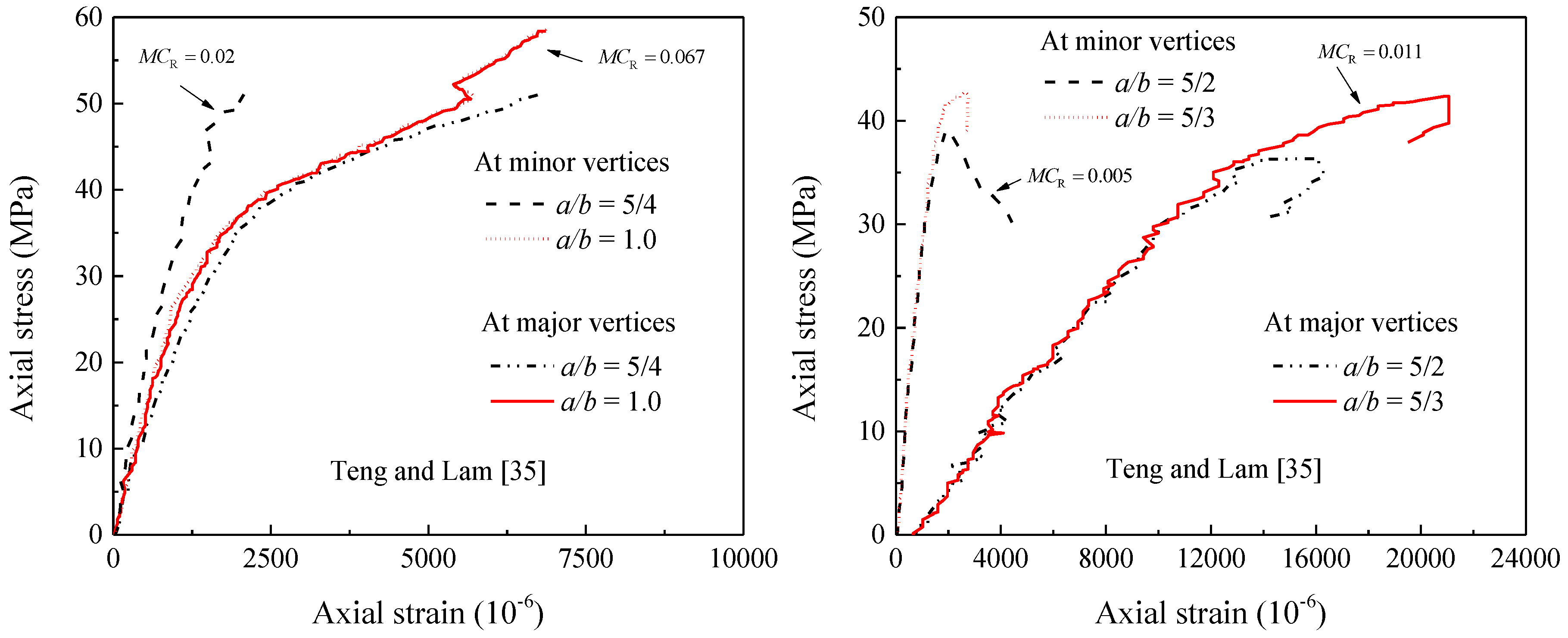
In the next section, the overall performance of the proposed and existing models available for FRP-confined concrete in elliptical cross sections was evaluated against the strength and strain data of specimens summarized in Table 1. In the current discussions, the proposed confinement pressure model is further checked through comparisons made between the stress-strain test responses of selected specimens shown in Table 1 and the analytical results from the model. These results were selected due to the following important reasons: (1) they had varying aspect ratios of cross-sections, (2) they had different unconfined concrete strengths, (3) they had varying levels of FRP confinement, and (4) the specimens of Yan [26] were with two types of FRP materials. In general, the comparison of the results with the predicted confinement pressure ratios in Figure 5 indicates that the proposed model can distinguish between the specimens’ responses.
5. Accuracy of the Proposed and Existing Strength and Strain Models
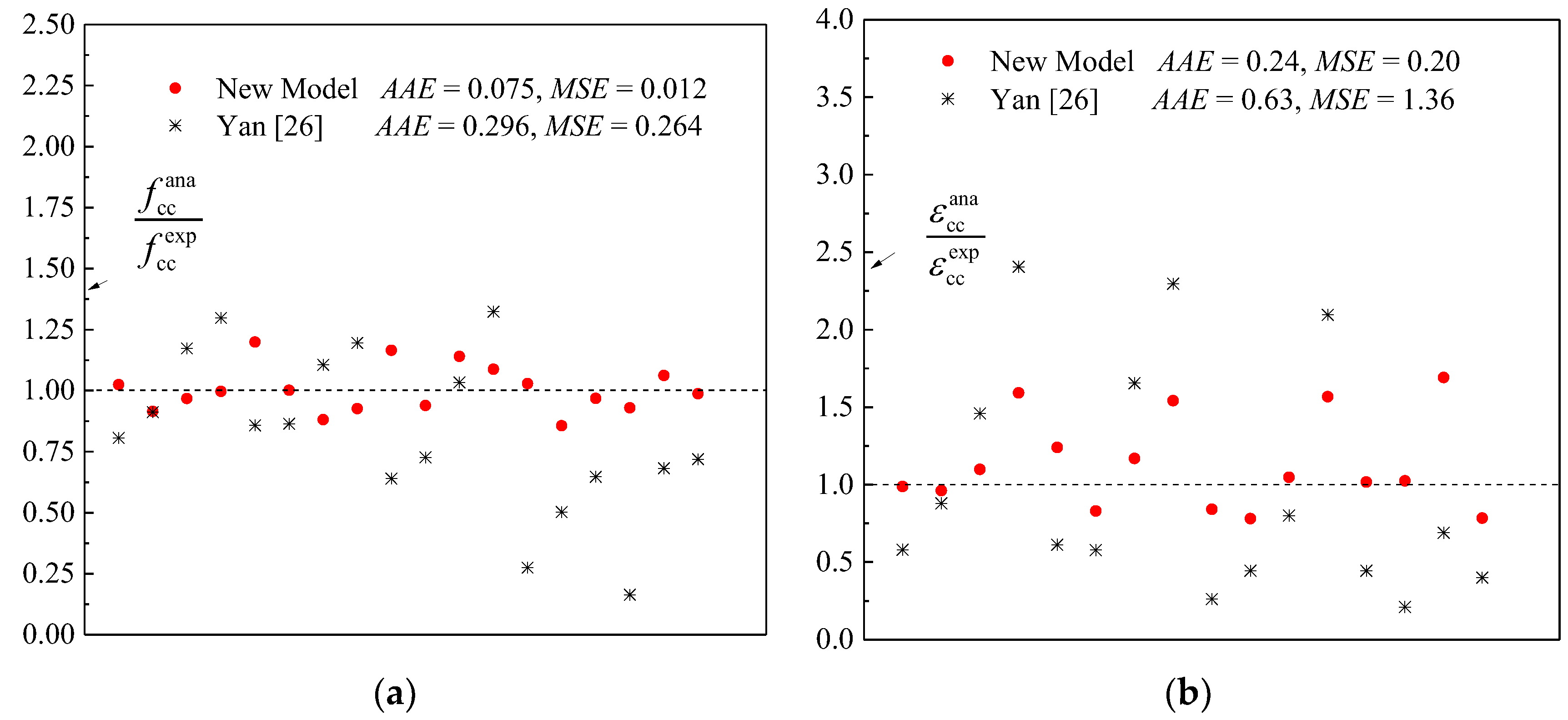
In this subsection, the performance of existing models that are proposed for estimating the confined strength and strain enhancements of elliptical–sectioned columns due to the confinement provided by the FRP is assessed against the experimental results summarized in Table 1. To check the overall model accuracy, the two factors, namely, (1) the average absolute error (AAE) (Equation (11)) and (2) the mean square error (MSE) (Equation (12)) are used. It should be noted that there are no other comparisons in the figure with other results and models due to the very limited research conducted on the axial compressive behavior of FRP confined concrete in elliptical cross sections. As reported in the figures, Equations (7) and (8) are able to predict with good accuracy (AAE = 7.5% and MSE = 12%) the fcc′ but show less accuracy (AAE = 24.0% and MSE = 20.0%) in predicting the corresponding strain εcc. Significant variability in the confined strain values was also reported in numerous studies (e.g., Hany et al. [52,53]). It can be generally observed from the comparisons provided in Figure 6a,b that the analytical values given by the proposed Equations (7) and (8) agree well with the test results compared with the model proposed by Yan [26].
where (modi − expi) = the difference between the predicted value by the proposed model and that measured for the tested specimen i; N is the total number of specimens.
6. Conclusions
The existing tests and analytical models on the axial compressive behavior of FRP-confined concrete have been largely concerned with circular-sectioned columns, where the concrete exhibited higher confinement due to uniform distribution of lateral stresses. On the contrary, the stress distribution in the case of a rectangular column varies over its cross section. Generally, the efficiency of FRP confinement decreases as the cross-sectional aspect ratio increases. Significant enhancements in ultimate strengths over the unconfined concrete strength were achieved for columns with an aspect ratio of less than 2.0. In particular, a reduction in ultimate strength was for lightly confined columns with an aspect ratio equal to 2.0. The effectiveness of confinement can be significantly improved by conducting a shape modification technique. On the basis of the evaluation of existing models, it was revealed that the models available for rectangular specimens do not predict well the results of concrete modified with elliptical FRP jackets. Based on a regression analysis of the existing test results, a new model consisting of several expressions was therefore introduced to estimate the strength and strain of FRP-confined concrete columns with elliptical cross sections. Based on the proposed expressions and the same test results, the sufficiently confined concrete threshold of 0.02 was proposed. Exceeding this value dictates that the post-peak curve of the stress-strain response exhibits a hardening behavior. The proposed model better predicted the test results compared with the predictions obtained from the existing models.
The model of the current study is based on limited tests compiled from the available literature. Since the stress-strain behavior of FRP-confined columns is dependent on several parameters, the proposed model may not be applicable to parameters that are out of the range considered in the analysis. More clearly, the number of specimens was 26, in which only 7 specimens had a circular section. The assumption made regarding the efficiency coefficient for the FRP-confined elliptical sections is different than that of the circular sections, indicating the wider applicability of the model to elliptical columns with aspect ratios ranging between 1.28 and 2.50. More research work for expanding its application may consider the effects of internal hoop steel reinforcement on elliptical RC columns with larger section sizes and aspect ratios than commonly used in practice.
Author Contributions
H.F.I. and Z.W. contributed equally to this work.
Funding
This research received no external funding.
Conflicts of Interest
The authors declare no conflicts of interest.
Notation
| a&b | width and depth of an elliptical cross section |
| a/b | aspect ratio of an elliptical cross-section |
| twrap | thickness of FRP composite layers |
| Ef | tensile elastic modulus of FRP composite |
| ff | tensile strength of FRP composite |
| εfu | FRP ultimate strain at rupture stage |
| fc′ | strength of unconfined concrete |
| ρf | volumetric ratio of FRP |
| εco | axial strain of unconfined concrete |
| εfe | effective hoop strain of FRP |
| kε | efficiency factor for determining the actual FRP hoop strain |
| ke | coefficient of confinement effectiveness |
| CR or MCR | FRP confinement pressure ratio |
| fcc′ | FRP-confined peak strength |
| εcc | axial strain of confined concrete |
| AAE | average absolute error |
| MSE | mean square error |
| N | total number of tested specimens |
| ana | analytical value given by the model |
| exp | experimental value obtained from tests |
References
- Moran, D.A.; Pantelides, C.P. Stress-strain model for fiber-reinforced polymer-confined concrete. J. Compos. Construct. 2002, 6, 233–240. [Google Scholar] [CrossRef]
- Ilki, A.; Kumbasar, N. Behavior of damaged and undamaged concrete strengthened by carbon fiber composite sheets. Struct. Eng. Mech. 2002, 13, 75–90. [Google Scholar] [CrossRef]
- Albanesi, T.; Nuti, C.; vanzi, I. Closed form constitutive relationship for concrete filled FRP tubes under compression. Const. Build. Mater. 2007, 21, 409–427. [Google Scholar] [CrossRef]
- Vintzileou, E.; Panagiotidou, E. An empirical model for predicting the mechanical properties of FRP-confined concrete. Const. Build. Mater. 2008, 22, 841–854. [Google Scholar] [CrossRef]
- Lignola, G.P.; Prota, A.; Manfredi, G.; Cosenza, E. Unified theory for confinement of RC solid and hollow circular columns. Compos. Part B-Eng. 2008, 39, 1151–1160. [Google Scholar] [CrossRef]
- Micelli, F.; Modarelli, R. Experimental and analytical study on properties affecting the behaviour of FRP-confined concrete. Compos. Part B-Eng. 2013, 45, 1420–1431. [Google Scholar] [CrossRef]
- Lim, J.C.; Ozbakkaloglu, T. Unified stress-strain model for FRP and actively confined normal-strength and high-strength concrete. J. Compos. Construct. 2015, 19, 1–14. [Google Scholar] [CrossRef]
- Cascardi, A.; Micelli, F.; Aiello, M.A. Unified model for hollow columns externally confined by FRP. Eng. Struct. 2016, 111, 119–130. [Google Scholar] [CrossRef]
- Cascardi, A.; Micelli, F.; Aiello, M.A. An artificial networks model for the prediction of compressive strength of FRP-confined concrete circular columns. Eng. Struct. 2017, 140, 199–208. [Google Scholar] [CrossRef]
- Sadeghian, P.; Fillmore, B. Strain distribution of basalt FRP-wrapped concrete cylinders. Case Stud. Construct. Mater. 2018, 9, e00171. [Google Scholar] [CrossRef]
- Lam, L.; Teng, J.G. Design-oriented stress-strain model for FRP-confined concrete in rectangular columns. J. Reinf. Plast. Compos. 2003, 22, 1149–1186. [Google Scholar] [CrossRef]
- Anselm, E. Stress-Strain Behavior of Rectangular Columns Confined with FRP Sheets. Master’s Thesis, University of Alabama, Huntsville, AL, USA, 2005. [Google Scholar]
- Pham, T.M.; Hadi, M.N.S. Stress prediction model for FRP confined rectangular concrete columns with rounded corners. J. Compos. Construct. 2014, 18. [Google Scholar] [CrossRef]
- Triantafyllou, G.G.; Roisakis, T.C.; Karabinis, A.I. Axially loaded reinforced concrete columns with a square section partially confined by light GFRP straps. J. Compos. Construct. 2014, 19. [Google Scholar] [CrossRef]
- Triantafillou, T.C.; Choutopoulou, E.; Fotaki, E.; Skorda, M.; Stathopoulou, M.; Karlos, K. FRP confinement of wall-like reinforced concrete columns. Mater. Struct. 2016, 49, 651–664. [Google Scholar] [CrossRef]
- Isleem, H.F.; Wang, D.Y.; Wang, Z.Y. A new numerical model for polymer-confined rectangular concrete columns. Proc. Inst. Civ. Eng. ICE Struct. Build. 2018. [Google Scholar] [CrossRef]
- Isleem, H.F.; Wang, D.Y.; Wang, Z.Y. Modeling the axial compressive stress-strain behavior of CFRP-confined rectangular RC columns under monotonic and cyclic loading. Compos. Struct. 2018, 185, 229–240. [Google Scholar] [CrossRef]
- Isleem, H.F.; Wang, Z.Y.; Wang, D.Y.; Smith, S.T. Monotonic and cyclic axial compressive behavior of CFRP-confined rectangular RC columns. J. Compos. Construct. 2018, 22, 292–300. [Google Scholar] [CrossRef]
- Isleem, H.F.; Wang, D.Y.; Wang, Z.Y. Axial stress-strain model for square concrete columns internally confined with GFRP hoops. Mag. Concr. Res. 2018, 70, 1064–1079. [Google Scholar] [CrossRef]
- Isleem, H.F.; Wang, Z.Y. A new strength prediction model for rectangular RC columns strengthened with CFRP wraps and anchors. Proc. Inst. Civ. Eng. Struct. Build. 2018. under review. [Google Scholar]
- Isleem, H.F.; Tahir, M.; Wang, Z.Y.; Wang, D.Y. Axial stress-strain model developed for large-sized rectangular RC columns confined with CFRP wraps and anchors. J. Bridge. Eng. 2018. under review. [Google Scholar]
- Isleem, H.F.A. Cyclic Axial Behavior of Rectangular RC Columns Strengthened with CFRP Composites. Master’s Thesis, Harbin Institute of Technology, Harbin, China, 2015. [Google Scholar]
- Wu, Y.F.; Zhou, Y.W. Unified strength model based on Hoek-Brown failure criterion for circular and square concrete columns confined by FRP. J. Compos. Construct. 2010, 14, 175–184. [Google Scholar] [CrossRef]
- Al-Salloum, Y.A. Influence of edge sharpness on the strength of square concrete columns confined with FRP composite laminates. Compos. Part B-Eng. 2007, 38, 640–650. [Google Scholar] [CrossRef]
- Tsai, K.C.; Lin, M.L. Seismic jacketing of RC columns for enhanced axial load carrying performance. J. Chin. Inst. Eng. 2002, 25, 389–402. [Google Scholar] [CrossRef]
- Yan, Z.H. Shape Modification of Rectangular Columns Confined with FRP Composites. Ph.D. Thesis, University of Utah, Salt Lake County, UT, USA, 2005. [Google Scholar]
- Pantelides, C.P.; Yan, Z. Confinement model of concrete with externally bonded FRP jackets or posttensioned FRP shells. J. Struct. Eng. 2007, 133, 1288–1296. [Google Scholar] [CrossRef]
- Yan, Z.; Pantelides, C.P. Concrete column shape modification with FRP shells and expansive cement concrete. Const. Build. Mater. 2011, 25, 396–405. [Google Scholar] [CrossRef]
- Xu, L. Shape Modification of Square Reinforced Concrete Columns Confined with Fiber-Reinforced Polymer and Steel Straps. Master’s Thesis, University of Wollongong, Wollongong, Australia, 2012. [Google Scholar]
- Zeng, J.J.; Guo, Y.C.; Gao, W.Y.; Li, J.Z.; Xie, J.H. Behavior of partially and fully FRP-confined circularized square columns under axial compression. Const. Build. Mater. 2017, 152, 319–332. [Google Scholar] [CrossRef]
- Jameel, M.T.; Sheikh, M.N.; Hadi, M.N.S. Behaviour of circularized and FRP wrapped hollow concrete specimens under axial compressive load. Compos. Struct. 2017, 171, 538–548. [Google Scholar] [CrossRef]
- Priestley, M.J.N.; Seible, F.; Xiao, Y.; Verma, R. Steel jacket retrofitting of reinforced concrete bridge columns for enhanced shear strength-Part 1: Theoretical considerations and test design. ACI Struct. J. 1994, 91, 394–405. [Google Scholar]
- Priestley, M.J.N.; Seible, F. Design of seismic retrofit measures for concrete and masonry structures. Const. Build. Mater. 1995, 9, 365–377. [Google Scholar] [CrossRef]
- Alsayed, S.H.; Almusallam, T.H.; Ibrahim, S.M.; Al-Hazmi, N.M.; Al-Salloum, Y.A.; Abbas, H. Experimental and numerical investigation for compression response of CFRP strengthened shape modified wall-like RC columns. Const. Build. Mater. 2014, 63, 72–80. [Google Scholar] [CrossRef]
- Teng, J.G.; Lam, L. Compressive behavior of carbon fiber reinforced polymer-confined concrete in elliptical columns. J. Struct. Eng. 2002, 128, 1535–1543. [Google Scholar] [CrossRef]
- Parvin, A.; Schroeder, J.M. Investigation of eccentrically loaded CFRP-confined elliptical concrete columns. J. Compos. Construct. 2008, 12, 93–101. [Google Scholar] [CrossRef]
- Rochette, P.; Labossiére, P. Axial testing of rectangular column models confined with composites. J. Compos. Construct. 2000, 4, 129–136. [Google Scholar] [CrossRef]
- Wang, Z.Y.; Wang, D.Y.; Smith, S.T.; Lu, D.G. CFRP-confined square RC columns. I: Experimental investigation. J. Compos. Construct. 2012, 16, 150–160. [Google Scholar] [CrossRef]
- Wu, G.; Wu, Z.S.; Lu, Z.T. Design-oriented stress-strain model for concrete prisms confined with FRP composites. Const. Build. Mater. 2007, 21, 1107–1121. [Google Scholar] [CrossRef]
- Teng, J.G.; Jiang, T.; Lam, L.; Luo, Y.Z. Refinement of a design-oriented stress-strain model for FRP-confined concrete. J. Compos. Construct. 2009, 13, 269–278. [Google Scholar] [CrossRef]
- Shao, Y.; Zhu, Z.; Mirmiran, A. Cyclic modeling of FRP-confined concrete with improved ductility. Cem. Concr. Compos. 2006, 28, 959–968. [Google Scholar] [CrossRef]
- Karantzikis, M.; Papanicolaou, C.G.; Antonopoulos, C.P.; Triantafillou, T.C. Experimental Investigation of Nonconventional Confinement for Concrete Using FRP. J. Compos. Construct. 2005, 9, 480–487. [Google Scholar] [CrossRef]
- Campione, G.; Fossetti, M. Compressive behaviour of concrete elliptical columns confined by single hoops. Eng. Struct. 2007, 29, 408–417. [Google Scholar] [CrossRef]
- Bournas, D.A.; Triantafillou, T.C. Bar Buckling in RC Columns Confined with Composite Materials. J. Compos. Construct. 2011, 15, 393–403. [Google Scholar] [CrossRef]
- Rousakis, T.C.; Karabinis, A.I. Adequately FRP confined reinforced concrete columns under axial compressive monotonic or cyclic loading. Mater. Struct. 2012, 45, 957–975. [Google Scholar] [CrossRef]
- Rousakis, T.C.; Tourtoutas, I.S. Modeling of passive and active external confinement of RC columns with elastic material. J. Appl. Math. Mech. 2015. [Google Scholar] [CrossRef]
- Bai, Y.L.; Dai, J.G.; Teng, J.G. Buckling of steel reinforcing bars in FRP-confined RC columns: An experimental study. Const. Build. Mater. 2017, 140, 403–415. [Google Scholar] [CrossRef]
- Zeng, J.J.; Lin, G.; Teng, J.G.; Li, L.J. Behavior of large-scale FRP-confined rectangular RC columns under axial compression. Eng. Struct. 2018, 174, 629–645. [Google Scholar] [CrossRef]
- Rousakis, T.C. Inherent seismic resilience of RC columns externally confined with nonbonded composite ropes. Compos. Part B-Eng. 2018, 135, 142–148. [Google Scholar] [CrossRef]
- Wan, B.; Jiang, C.; Wu, Y.F. Effect of defects in externally bonded FRP reinforced concrete. Const. Build. Mater. 2018, 172, 63–76. [Google Scholar] [CrossRef]
- Ilki, A.; Peker, O.; Karamuk, E.; Demir, C.; Kumbasar, N. FRP retrofit of low and medium strength circular and rectangular reinforced concrete columns. J. Mater. Civ. Eng. 2008, 20, 169–188. [Google Scholar] [CrossRef]
- Hany, N.F.; Hantouche, E.G.; Harajli, M.H. Axial stress-strain model of CFRP-confined concrete under monotonic and cyclic loading. J. Compos. Construct. 2015, 16. [Google Scholar] [CrossRef]
- Hany, N.F.; Hantouche, E.G.; Harajli, M.H. Generalized axial stress-strain response of rectangular columns confined using CFRP jackets and anchors. J. Compos. Construct. 2017, 21. [Google Scholar] [CrossRef]
Figure 1.
Effect of FRP confinement stiffness on hoop strain ((a) specimens of Teng and Lam [35] and (b) specimens of Yan [26]): εfe = average FRP hoop strain from gauges on minor and major section sides; εfu = FRP tensile strain obtained from flat test coupons.

Figure 2.
Effect of aspect ratio on FRP hoop strain ((a) specimens of Teng and Lam [35] and (b) specimens of Yan [26]): εfe = average FRP hoop strain from gauges on minor and major section sides; εfu = FRP tensile strain obtained from flat test coupons.

Figure 3.
Effective confined concrete area in elliptical-sectioned column: (a) an elliptical jacketing scheme for an excising rectangular-sectioned column; (b) a rectangular concrete block with the same aspect ratio is considered, internal to the elliptical concrete section.
Figure 3.
Effective confined concrete area in elliptical-sectioned column: (a) an elliptical jacketing scheme for an excising rectangular-sectioned column; (b) a rectangular concrete block with the same aspect ratio is considered, internal to the elliptical concrete section.

Figure 4.
Relationship between effective confinement pressure ratio and ratio of the confined peak strength to the unconfined concrete strength.
Figure 4.
Relationship between effective confinement pressure ratio and ratio of the confined peak strength to the unconfined concrete strength.

Figure 5.
Accuracy of the proposed confinement pressure model MCR against selected stress-strain test responses of specimens in Table 1.
Figure 5.
Accuracy of the proposed confinement pressure model MCR against selected stress-strain test responses of specimens in Table 1.


Figure 6.
Comparisons of predictions made by the proposed and existing models with experimental test results: (a) confined peak strength (Equation (7)); (b) corresponding axial strain (Equation (8)).
Figure 6.
Comparisons of predictions made by the proposed and existing models with experimental test results: (a) confined peak strength (Equation (7)); (b) corresponding axial strain (Equation (8)).


Table 1.
Summary of fiber-reinforced polymers (FRP) reinforcement, material, and mechanical properties of test specimens.
Table 1.
Summary of fiber-reinforced polymers (FRP) reinforcement, material, and mechanical properties of test specimens.
| No. | Specimen | Section Details | Material Properties | ||||||
|---|---|---|---|---|---|---|---|---|---|
| a (mm) | b (mm) | a/b | fc′ (MPa) | twrap (mm) | ff (MPa) | Ef (GPa) | εfu (%) | ||
| Teng and Lam [35] | |||||||||
| Series 1 | |||||||||
| 1 | S1.0L1 | 152.2 | 152.2 | 1.00 | 48.8 | 0.165 | 3983 | 263 | 1.514 |
| 2 | S5/4L1 | 168.2 | 131.6 | 1.28 | 48.8 | 0.165 | 3983 | 263 | 1.514 |
| 3 | S5/3L1 | 194.8 | 115.6 | 1.69 | 48.8 | 0.165 | 3983 | 263 | 1.514 |
| 4 | S5/2L1 | 237.6 | 94.8 | 2.51 | 48.8 | 0.165 | 3983 | 263 | 1.514 |
| Series 2 | |||||||||
| 5 | S1.0L1 | 151.6 | 151.6 | 1.00 | 47.1 | 0.110 | 3824 | 276 | 1.386 |
| 6 | S5/4L1 | 168.4 | 131.6 | 1.28 | 47.1 | 0.165 | 3983 | 263 | 1.514 |
| 7 | S5/3L1 | 194.9 | 114.8 | 1.70 | 47.1 | 0.165 | 3983 | 263 | 1.514 |
| 8 | S5/2L1 | 236.5 | 95.0 | 2.49 | 47.1 | 0.165 | 3983 | 263 | 1.514 |
| Series 3 | |||||||||
| 9 | S1.0L0 | 151.9 | 151.9 | 1.00 | 43.5 | - | - | - | - |
| 10 | S5/4L0 | 168.5 | 131.6 | 1.28 | 43.5 | - | - | - | - |
| 11 | S5/3L0 | 194.8 | 115.9 | 1.68 | 43.5 | - | - | - | - |
| 12 | S5/2L0 | 237.8 | 94.6 | 2.51 | 43.5 | - | - | - | - |
| Series 4 | |||||||||
| 13 | S1.0L0 | 152.0 | 152.0 | 1.00 | 44.6 | - | - | - | - |
| 14 | S5/4L0 | 168.7 | 131.4 | 1.28 | 44.6 | - | - | - | - |
| 15 | S5/3L0 | 194.8 | 115.0 | 1.69 | 44.6 | - | - | - | - |
| 16 | S5/2L0 | 236.8 | 94.6 | 2.50 | 44.6 | - | - | - | - |
| Series 5 | |||||||||
| 17 | S1.0L2 | 152.3 | 152.3 | 1.00 | 45.8 | 0.220 | 3824 | 276 | 1.386 |
| 18 | S5/4L2 | 168.2 | 131.9 | 1.28 | 45.8 | 0.220 | 3824 | 276 | 1.386 |
| 19 | S5/3L2 | 194.8 | 115.0 | 1.69 | 45.8 | 0.220 | 3824 | 276 | 1.386 |
| 20 | S5/2L2 | 237.6 | 94.6 | 2.51 | 45.8 | 0.220 | 3824 | 276 | 1.386 |
| Yan [26] | |||||||||
| Series 1 | |||||||||
| 21 | S-CT-F | 406.4 | 406.4 | 1.00 | 15.1 | 1.930 | 1220.4 | 86.9 | 1.442 |
| 22 | R2-CT-F | 647.7 | 419.1 | 1.55 | 15.2 | 1.930 | 1220.4 | 86.9 | 1.405 |
| 23 | R3-CT-F | 746.1 | 381.0 | 1.96 | 15.2 | 1.930 | 1220.4 | 86.9 | 1.405 |
| Series 2 | |||||||||
| 24 | S-GT-F | 406.4 | 406.4 | 1.00 | 17.6 | 9.754 | 227.5 | 16.9 | 1.365 |
| 25 | R2-GT-F | 692.2 | 355.6 | 1.95 | 15.2 | 9.754 | 227.5 | 16.9 | 1.347 |
| 26 | R3-GT-F | 739.8 | 311.2 | 2.38 | 15.2 | 9.754 | 227.5 | 16.9 | 1.347 |
Note:a = depth of a cross-section, b = width of a cross-section, a/b = aspect ratio of a cross section, twrap = total thickness of FRP composite layers, ff = maximum tensile strength of FRP composite, Ef = tensile elastic modulus of FRP composite, εfe = average FRP strain obtained using strain gauges installed on the FRP surface at the four vertices (minor and major sides of a cross section), εfu = FRP tensile strain obtained from flat test coupons, and fc′ = axial compressive strength of unconfined concrete.
Table 2.
Published models of boundary value for sufficiently confined concrete.
| Published Model | Specimen Type | Boundary Value |
|---|---|---|
| Pham and Hadi [13] | Circular, rectangular | CR2 ≥ 0.15 |
| Yan [26] | Circular, rectangular, and elliptical | CR1 ≥ 0.2 |
| Shao et al. [41] | Circular | CR3 ≥ 0.3 |
| Source/Specimen | S1.0L1 | S5/4L1 | S5/3L1 | S5/2L1 | S1.0L1 | S5/4L1 |
| fcc′/fc′ | 1.240 | 1.096 | 0.852 | 0.770 | 1.166 | 1.157 |
| Pham and Hadi [13] | 0.129 | 0.159 | 0.159 | 0.157 | 0.134 | 0.165 |
| Evaluation | satisfied | unsuitable | satisfied | satisfied | Satisfied | unsuitable |
| Yan [26] | 0.047 | 0.034 | 0.020 | 0.002 | 0.049 | 0.035 |
| Evaluation | unsuitable | unsuitable | satisfied | satisfied | unsuitable | unsuitable |
| Shao et al. [41] | 0.177 | 0.126 | 0.119 | 0.105 | 0.184 | 0.131 |
| Evaluation | unsuitable | unsuitable | satisfied | satisfied | unsuitable | unsuitable |
| Proposed MCR | 0.054 | 0.020 | 0.006 | 0.003 | 0.077 | 0.038 |
| Evaluation | satisfied | satisfied | satisfied | satisfied | Satisfied | satisfied |
| Source/Specimen | S5/3L1 | S5/2L1 | S1.0L2 | S5/4L2 | S5/3L2 | S5/2L2 |
| fcc′/fc′ | 0.904 | 0.837 | 1.563 | 1.376 | 0.967 | 0.755 |
| Pham and Hadi [13] | 0.165 | 0.163 | 0.171 | 0.211 | 0.211 | 0.209 |
| Evaluation | unsuitable | unsuitable | satisfied | satisfied | unsuitable | unsuitable |
| Yan [26] | 0.020 | 0.002 | 0.064 | 0.047 | 0.027 | 0.002 |
| Evaluation | satisfied | satisfied | unsuitable | unsuitable | satisfied | satisfied |
| Shao et al. [41] | 0.123 | 0.109 | 0.241 | 0.172 | 0.162 | 0.144 |
| Evaluation | satisfied | satisfied | unsuitable | unsuitable | satisfied | satisfied |
| Proposed MCR | 0.004 | 0.003 | 0.176 | 0.058 | 0.031 | 0.006 |
| Evaluation | satisfied | satisfied | satisfied | satisfied | satisfied | satisfied |
| Source/Specimen | S-CT-F | R2-CT-F | R3-CT-F | S-GT-F | R2-GT-F | R3-GT-F |
| fcc′/fc′ | 2.730 | 1.989 | 1.545 | 2.520 | 1.465 | 1.390 |
| Pham and Hadi [13] | 0.520 | 0.491 | 0.482 | 0.421 | 0.484 | 0.499 |
| Evaluation | satisfied | satisfied | satisfied | satisfied | satisfied | satisfied |
| Yan [26] | 0.210 | 0.080 | 0.041 | 0.168 | 0.042 | 0.014 |
| Evaluation | satisfied | unsuitable | unsuitable | unsuitable | unsuitable | unsuitable |
| Shao et al. [41] | 0.766 | 0.401 | 0.371 | 0.621 | 0.375 | 0.365 |
| Evaluation | unsuitable | unsuitable | unsuitable | unsuitable | satisfied | satisfied |
| Proposed MCR | 0.553 | 0.144 | 0.096 | 0.350 | 0.109 | 0.072 |
| Evaluation | satisfied | Satisfied | satisfied | satisfied | satisfied | satisfied |
If fcc′/fc′ ≥ 1.0, where the FRP confined specimen experienced enhancement in axial strength and had a final ascending stress-strain branch, then the confinement pressure models provided in Table 2 are suitable. On contrary, for confined specimens with no strength enhancement, fcc′/fc’ < 1.0, the models are unsatisfied.
© 2018 by the authors. Licensee MDPI, Basel, Switzerland. This article is an open access article distributed under the terms and conditions of the Creative Commons Attribution (CC BY) license (http://creativecommons.org/licenses/by/4.0/).
Share and Cite
MDPI and ACS Style
Isleem, H.F.; Wang, Z. Axial Compressive Stress-Strain Model Developed for FRP-Confined Concrete Columns with Elliptical Cross Sections. J. Compos. Sci. 2018, 2, 67. https://doi.org/10.3390/jcs2040067
AMA Style
Isleem HF, Wang Z. Axial Compressive Stress-Strain Model Developed for FRP-Confined Concrete Columns with Elliptical Cross Sections. Journal of Composites Science. 2018; 2(4):67. https://doi.org/10.3390/jcs2040067
Chicago/Turabian StyleIsleem, Haytham F., and Zhenyu Wang. 2018. "Axial Compressive Stress-Strain Model Developed for FRP-Confined Concrete Columns with Elliptical Cross Sections" Journal of Composites Science 2, no. 4: 67. https://doi.org/10.3390/jcs2040067