Article

Influence of Cu Addition on the Wear Behavior of a Eutectic Al–12.6Si Alloy Developed by the Spray Forming Method

1
Department of Mechanical Engineering, Tontadarya College of Engineering, Gadag 582101, India
2
Department of Engineering, Manchester Metropolitan University, Manchester M15GD, UK
3
Department of Mechanical Engineering, St. Joseph Engineering College, Mangaluru 575028, India
4
Department of Mechanical Engineering, Basaveshwar Engineering College, Bagalkot 587101, India
5
Department of Civil Engineering and Geology, University of Madeira, Campus da Penteada, 9020-105 Funchal, Portugal
6
CQM-Centro de Química da Madeira, University of Madeira, Campus da Penteada, 9020-105 Funchal, Portugal
*
Author to whom correspondence should be addressed.
J. Compos. Sci. 2024, 8(3), 88; https://doi.org/10.3390/jcs8030088
Submission received: 19 January 2024 / Revised: 9 February 2024 / Accepted: 23 February 2024 / Published: 27 February 2024
(This article belongs to the Special Issue Metal Composites, Volume II)

Abstract

:
In the present study, the influence of the addition of copper (Cu) on the wear behavior of a Al-12.6Si eutectic alloy developed using the spray forming (SF) method was discussed, and the results were compared with those of as-cast (AC) alloys. The microstructural features of the alloys were examined using both optical and the scanning electron microscopy, and the chemical composition and phase identification were achieved by X-ray diffraction (XRD) analysis. The results revealed that the microstructure of binary the SF alloy consisted of fine primary and eutectic Si phases, evenly distributed in the equiaxed α-Al matrix, whereas the Cu-based SF ternary alloy consisted of uniformly distributed fine eutectic Si particulates and spherical-shaped θ-Al2Cu precipitates, uniformly distributed in α-Al matrix. In contrast, the AC ternary (Al-12.6Si-2Cu) alloy consisted of unevenly dispersed eutectic Si needles and the coarse intermetallic compound θ-Al2Cu in the α-Al matrix. The addition of Cu enhanced the micro hardness of the SF ternary alloy by 8, 34, and 41% compared to that of the SF binary, AC ternary, and binary alloys, respectively. The wear test was conducted using a pin-on-disc wear testing machine at different loads (10–40 N) and sliding velocities (1–3 ms−1). The wear tests revealed that SF alloys exhibited an improved wear behavior in the entire applied load and sliding velocity range in comparison to that of the AC alloys. At a load of 40 N and a sliding velocity of 1 ms−1, the wear rate of the SF2 alloy is 62, 47, and 23% lower than that of the AC1, AC2, and SF1 alloys, respectively. Similarly, at a sliding velocity of 3 ms−1, the wear rate of the SF2 alloy is 52%, 42%, and 21% lower than that of the AC1, AC2, and SF1 alloys, respectively. The low wear rate in the SF2 alloy was due to the microstructural modification during spray forming, the precipitation of fine Al2Cu intermetallic compounds, and increased solid solubility. The SF alloys show an increased transition from oxidative to abrasive wear, while the AC alloys demonstrate wear mechanisms that change from oxidative to abrasive, including delamination, with an increase in sliding velocity and load.

1. Introduction

The cast aluminum alloys are widely used in various industries, such as in the production of chemical vessels, aircraft, and automobiles, due to their lightweight nature, high strength, and excellent wear and corrosion resistance [1,2,3]. The most significant cast aluminum alloy system is the aluminum–silicon (Al-Si) alloy. The increase in the silicon content (4–13%) helps to produce excellent casting properties [4]. The Al-Si eutectic alloy is a cast structure made primarily of acicular/needle-shaped eutectic Si phases that are randomly distributed throughout the dendritic α-Al matrix. If the morphology of the Si particles is modified from a needle/rod-like shape to a nearly spherical/equiaxed shape, then its wear resistance can be improved. This modification can result in a strong bonding between the matrix and the Si particle, thereby reducing the stress concentration caused by needle/rod-shaped Si particles [5,6,7,8]. Several studies have been conducted to examine the impact of silicon particles on wear behavior. However, only a limited number of studies have focused on determining how the shape, size, and distribution of Si particles affect the dry sliding wear behavior of Al-Si alloys. Ahmad and Nabeel [9] have considered the effect of silicon particle morphology on the mechanical and wear properties of Al-Si alloys, while Hamza et al. [10] conducted a comprehensive investigation to establish the correlation between microstructure and wear behavior in Al7075-Ti alloys. In their study, Praveen and Wani reported that silicon particles with a lower aspect ratio exhibit improved wear resistance in Al-Si alloys [11]. Sandeep Jain et al. reported that as the Si content increased in the Al-Cu alloy, the hardness and wear resistance of the alloy increased [12]. However, some studies have found that hypereutectic Al-Si alloys with a high Si concentration showed a low wear-rate and an increased transition load [13]. The addition of certain alloying elements, such as iron, copper, manganese, chromium, magnesium, nickel, and zirconium, can improve the wear resistance of Al-Si alloys at both room and high temperatures. Among these, copper can be particularly effective due to its high solubility in aluminum. When copper combines with aluminum and silicon, it creates a stronger alloy due to the formation of an Al2Cu compound, which enhances the wear resistance of the alloy [14,15,16]. The addition of 1–4% Cu to the eutectic Al-Si alloy increases wear resistance and extends the wear transition period from mild to severe. This is due to the strengthening effect of the solid solution, precipitation hardening, and enhanced matrix hardness [17]. However, the addition of more than 2 wt.% of Cu did not affect the transient load and wear resistance of the Al-Si alloy [18]. The Al-Si-Cu alloy has a microstructure that consists of large Si intermetallic phases. These phases increase stress and reduce wear resistance. Furthermore, the intermetallic phase is hard and brittle, which poses a challenge with regards to the casting of parts [19]. Tash and Essam found that the θ-Al2Cu intermetallic phase decreased the wear rate in Cu-containing Al-Si alloys [20]. Raviraj et al. have observed in their work on composites that there was an improvement in selected mechanical properties compared to those of stir cast composites as the percentage of ZrO2 increased to 13 wt.% of silicon in the spray formed composites [21]. Various casting techniques have been used to refine the microstructure of the Al-Si alloy. One of these techniques is SF, which is a rapid solidification process. This process can produce near-net-shaped components with a homogeneous microstructure consisting of fine, equiaxed grains. The primary and eutectic Si, as well as the modified precipitates, will appear as fine, globular-shaped particulates [22]. Many studies have been carried out on the wear characteristics of Al-Si alloys manufactured through SF with varying amounts of Si. The obtained results showed that these alloys showed superior wear performance compared to those manufactured through conventional casting methods. Moreover, the addition of Cu and Mg as alloying elements in SF Al-Si alloys resulted in even lower wear rates than those observed in the binary Al-Si alloys [23]. Insufficient research exists on the tribological characteristics of the SF eutectic Al-Si alloy with the addition of Cu. The present study aims to examine the microstructural features and wear characteristics of both Al-12.6 Si and Al-12.6 Si-2Cu alloys produced by the SF technique and to compare them with those of AC alloys. The findings of this study will provide valuable insights into the influence of Cu on the tribological properties of the Al-Si alloy. The results will be useful for researchers, industry professionals, and stakeholders in developing improved materials for tribological applications.

2. Materials and Methods

The Al-12.6Si and Al-12.6Si-2Cu alloys were prepared from the master alloys of Al (99.7%), Al-20Si, and Al-50Cu alloys. Table 1 shows the chemical composition of the alloys. The SF process was used to produce the Al-12.6Si (SF1) and Al-12.6Si-2Cu (SF2) alloys, and the details of the SF process have been described elsewhere [24,25]. Table 2 shows the list of the process parameters employed in the present work. A free-fall atomizer was employed to atomize the superheated liquid metal stream using nitrogen gas. The flow diagram of the SF process is depicted in Figure 1.
The samples of the AC and secondary processed SF Al–12.6Si and Al–12.6Si–2Cu alloys were prepared [Silicarb Recrystallized Pvt Ltd., Karnataka, India] using standard metallographic techniques and were etched with Keller’s reagent for the exploration of the microstructural features. The microstructural features were studied under an optical microscope and a scanning electron microscope (SEM). The hardness measurement was carried out using an HV-5 VH tester at a load of 300 g and a dwell period of 15 s with a procedures of ASTM E92 (2004).The dry sliding wear testing was carried out on a pin-on-disk tribometer as per ASTM: G99-05 (2016). The disk was made of EN-32 steel with a hardness of 65HRC. The wear specimens were Ø8 × 30 mm in size and were polished and cleaned with acetone before being tested. The wear tests were performed at different loads, ranging from 10 to 40 N, for a sliding distance of 2000 m at sliding velocities of 1, 2, 2.5 and 3 m/s. The topographical features of the worn-out surfaces were analyzed using SEM.

3. Results and Discussion

3.1. Porosity Measurement

The porosity has been observed to be an inevitable entity in SF alloys. However, depending on the location and processing parameters, its proportion and features in the preform are subject to change. The porosity heavily influences the mechanical, wear, and corrosion properties of the alloys. In the current investigation, hot pressing was used for porosity reduction in the alloys. The porosity values reported are shown in Table 3. In comparison to SF1 alloy, the SF2 alloy exhibits less porosity after hot compaction. The variation in monitoring the process parameters in SF may be the cause for the variation in porosity in the alloys before hot compaction. The increasing surface heat condition of the preforms during deposition has a significant effect on the nature and amount of porosity. As a result, minimizing preform porosity requires careful control of the processing parameters. Many researchers have investigated how porosity develops during SF [26]. The high liquid fraction in the spray typically causes gas to become trapped within the liquid, resulting in spherical holes. The SF1 alloy exhibited a higher porosity than did the SF2 alloy before hot compaction. This can be due to the fact that the spray contains a significant amount of liquid. In the spray deposited alloys, the porosity was significantly reduced by hot compaction.

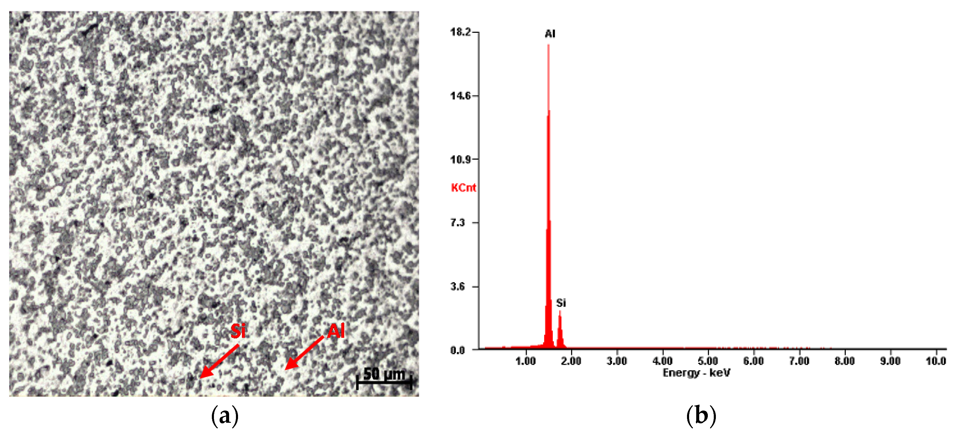
3.2. Microstructural Features of AC and SF Alloys

The optical microstructure of the AC1 alloy is shown in Figure 2a. It consists of eutectic Si needles dispersed randomly throughout the α-Al matrix. The EDX (energy dispersive X-ray) spectrum of the AC1 alloy is shown in Figure 2b. The Al and Si peaks in the spectrum are particularly prominent. As shown in Figure 3a, the SF1 alloy microstructure was composed of evenly dispersed, fine eutectic Si particulates. The EDX spectrum of the SF1 alloy is shown in Figure 3b. Additionally, it was found that the matrix of the SF1 alloy included a 7 vol.% of micron-sized porosity and showed an improved solid solubility of Si. The high fraction of liquid in the spray causes the entrapment of gas in the liquid, which results in the formation of pores in the alloy [26]. However, the amount of porosity was not significantly influenced by the presence of Cu and Si.
The SEM micrograph of the AC2 alloy is shown in Figure 4. The micrograph depicts the random distribution of the eutectic Si phase, the θ-Al2Cu phase, and the Q-Al-Si-Cu phase in the dendritic α-Al matrix. At the grain boundaries of the Al dendrite arms, the intermetallic θ and Q phases were found to be coarse, ranging in size from 50 to 75 μm. Table 4 displays the composition of the AC2 alloy, as determined by EDX analysis at spots 1, 2, 3 and 4 as shown on the microstructure.
Figure 5a depicts the SEM microstructure of the SF2 alloy. The microstructure of the alloy showed fine precipitates of θ-Al2Cu and Q-phases in an equiaxed Al matrix, as well as a uniform, homogeneous distribution of fine eutectic Si particles, with sizes ranging from 3 to 7 μm. The EDS spectra of spots 1, 2 and 3 of Figure 5a are shown in Figure 5b(i,ii,iii) respectively. The EDX analysis of the SF2 alloy has revealed fine eutectic Si, fine precipitates of θ-Al2Cu, and Q-Al74Si9Cu10 phases.
Table 5 displays the composition of the phases. After being hot pressed, the microstructure of the SF2 alloy (Figure 5a) showed eutectic Si and θ phase fragmentation. Additionally, an increase in the volume percentage of the Si phases, a decrease in porosity, and a homogeneous Al-matrix were observed. The fine θ and Q-intermetallic compounds began to precipitate at room temperature as a result of the alloy’s rapid cooling during the atomization and deposition process, which maintained all of the solute in a supersaturated state.

3.3. Hardness

Table 6 displays the micro-hardness values of the AC and SF alloys. In comparison to AC alloys, the results show a considerable increase in the microhardness of the SF alloys. The hardness of the SF1 alloy is 36% greater than that of the AC1 alloy, while the hardness of the SF2 alloy is 33% higher than that of the AC2 alloy. The SF2 is invariably 41% harder than that of the AC1 alloy. The small and hard Si particles, which are uniformly dispersed throughout the Al matrix and that resist localized deformation when the indentation is applied, may be the cause for the high hardness of the spray deposited alloys. The plastic deformation was significantly hampered by the fine eutectic Si phase. The high hardness of the SF2 alloy may be attributed to the fine precipitation of the hard Al2Cu intermetallic phase, distributed uniformly throughout the Al matrix, and a higher volume fraction of eutectic Si, which causes an obstruction in the indentation and raises the hardness [23]. Additionally, the SF process, being a rapid solidification process, has produced more fine precipitates and a hardening effect, which may have contributed to the resulting increased hardness by adding another barrier to the dislocation motion [27].

3.4. Wear Characteristics of AC and SF Alloys

3.4.1. Variation of Wear Rate with Load at Constant Sliding Velocity

The wear rates of both the AC and SF alloys are shown in Figure 6a–d. The alloys were tested for wear at sliding velocities of 1, 2, 2.5, and 3 ms−1, with a sliding distance of 2000 m and a load range of 10–40 N. The results show that the wear rate increases for all alloys as the load is increased, regardless of the type of alloy or sliding velocity. Additionally, it was observed that AC alloys consistently exhibit a higher wear rate than that of the SF alloys. Among the tested alloys, the SF2 alloy has the lowest wear rate, while the AC1 alloy has the highest wear rate across the whole range of applied loads and sliding velocities.
During wear testing, the long eutectic Si needles tend to break more frequently than the tiny Si particles. This is due to an increase in the alloy’s shear stress as the load increases, which results in easier fracturing of the eutectic Si and deformation of the matrix around it. The size of the eutectic Si may influence the stress concentration caused by deformation, with the interface between Si needles and the α-Al matrix being more susceptible to this effect than the interface between the tiny Si particles and the α-Al matrix. In the present study, this was observed, as coarse eutectic Si fractured easily, leading to the decreased wear resistance of the AC alloys. However, in spray deposition, the eutectic Si is more finely divided and evenly dispersed throughout the α-Al matrix. The wear resistance of AC2 alloy is higher than that of AC1 alloy, and SF2 alloy has a higher wear resistance than the SF1 alloy. This is because of the presence of the θ phase in the ternary alloy.
The strengthening effect of the θ phase on the α-Al matrix lowers the possibility of the Si needles peeling off from the matrix, decreasing the wear rate. The secondary processed SF2 alloy has a better wear resistance than does the AC2 alloy. This is because of the uniform distribution of the refined eutectic Si and the fine precipitates of the θ-Al2Cu intermetallic phase in the α-Al matrix. The Si and θ phases in the alloy have been further finely refined by hot compaction, decreasing the wear rate of the alloy [24]. The wear rate of the AC and SF alloys is low at a low load (10 N) and a low sliding velocity (1.0 ms−1), with no appreciable variation between the alloys (Figure 6a). There will be less contact between the mating surfaces, and at a low contact pressure, the interface temperature is adequate to produce metal oxide film, which will be removed from the pin surface during sliding. Therefore, oxidative wear was responsible for the separation of the oxidized film between the mating surfaces and the removal of oxides from the interface. The clear sign of a change in the wear behavior was the rise in wear rate as the applied load increased (from 10 to 20 N). The slope of the wear rate versus the applied load has been observed to increase at higher loads (greater than 20 N). This demonstrates that the wear process has switched from mild oxidative metallic wear to delamination pure metallic wear. At a high load, the sliding surface is subjected to high shear stress, which causes cracks and spreads beneath the plastically deformed surface, potentially eventually causing the alloy to delaminate from the surface. This underlying wear process causes the wear rate to increase with the load [28]. For both the SF and AC alloys, the wear rates increased at a 40 N load.

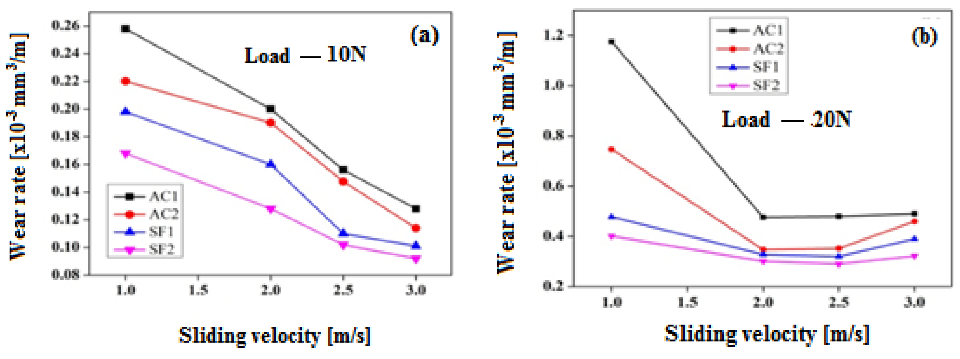
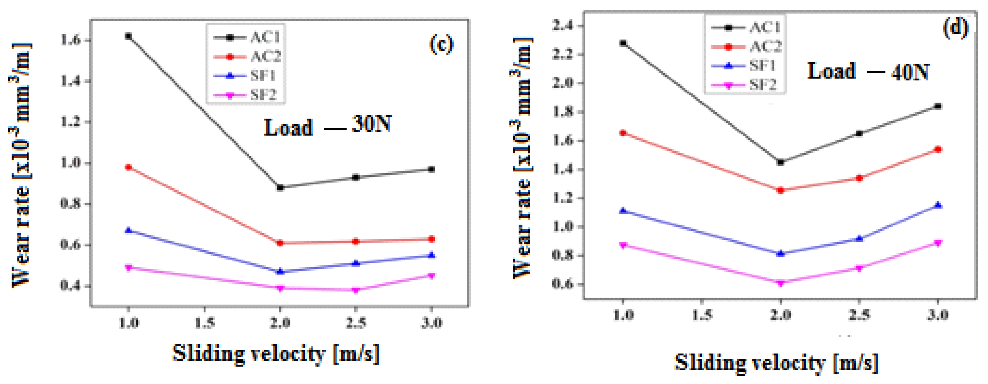
3.4.2. Variation of Wear Rate with Sliding Velocity at a Constant Applied Load

Understanding how the wear rate changes with sliding velocity at a constant load is crucial (refer to Figure 7a–d). At a low load of 10 N, the wear rate decreased as the sliding velocity increased (Figure 7a). Initially, the wear rate was high at a low sliding velocity of 1.0 ms−1. The lowest wear rate was found at 2.0 ms−1 for loads of 20 and 30 N, and the wear rate increased somewhat at higher sliding velocities (Figure 7b,c). However, at a high load of 40 N, the lowest measured wear rate was observed at a sliding velocity of 2.0 ms−1, and beyond 2.0 ms−1, the wear rate significantly increased (Figure 7d). Due to the friction force, a metal oxide layer forms on the pin surface, which then gets removed during the sliding process. Therefore, at low loads, only oxidative wear takes place. At a higher load of 40 N, adhesive wear takes over, where severe plastic deformation of the surface occurs. This causes a higher interface temperature, which then heats up the worn surface and softens the matrix. Furthermore, the worn surface experiences greater penetration and plastic deformation. As a result, both the AC and SF alloys experienced mixed adhesive and abrasive wear at higher loads. As per the study in Ref. [29], it has been observed that the wear rate decreases as the sliding speed increases up to a critical sliding velocity (2.0 ms−1). However, as the sliding speed increases beyond 2.0 ms−1, the wear rate starts to increase. This happens because the reduced surface contact between the pin and disc initially leads to lower wear rate, but the increase in sliding velocity raises the strain rate, improves the flow strength, and increases the flow rates, which eventually increases the wear rate [30]. Moreover, at higher sliding velocities (between 2 and 3 ms−1), the interface temperature increases due to the rise in friction heat, which makes the alloy softer. This leads to more surface contact, resulting in a higher wear rate [31].
During the SF process, the rapid solidification of alloys led to the development of fine eutectic Si, an increase in the volume fraction of the Si phase, and an increase in the solid solubility of Si in the matrix. This process reduced the stress concentration at the interface between the fine and spherical Si phase and the equiaxed Al matrix, which lowers the likelihood of the formation of subsurface cracks. Additionally, the strong interface bond strength with the matrix might improve the wear resistance of the SF alloys. The Cu addition improved the thermal stability of the Al-Si alloys by generating a hard θ-Al2Cu intermetallic compound in the Al matrix. This resulted in an increase in the transition period for both the SF and AC alloys, leading to mild to severe wear rate. In the SF2 alloy, the development of fine θ-Al2Cu intermetallic precipitates was coherent with the soft Al-matrix, which increased the hardness and wear resistance by resisting the dislocation motion. However, the presence of an extremely hard, coarse, and brittle θ-Al2Cu intermetallic phase, as well as the needle-like eutectic Si phase, in the α-Al matrix resulted in a high wear rate in the AC2 alloy. This faceted structure of intermetallic and Si phases existed as discrete particles that had a relatively weak bond with the matrix and served as stress raisers. The eutectic Si and hard intermetallic phases were also anticipated to have the potential for crack nucleation [32].

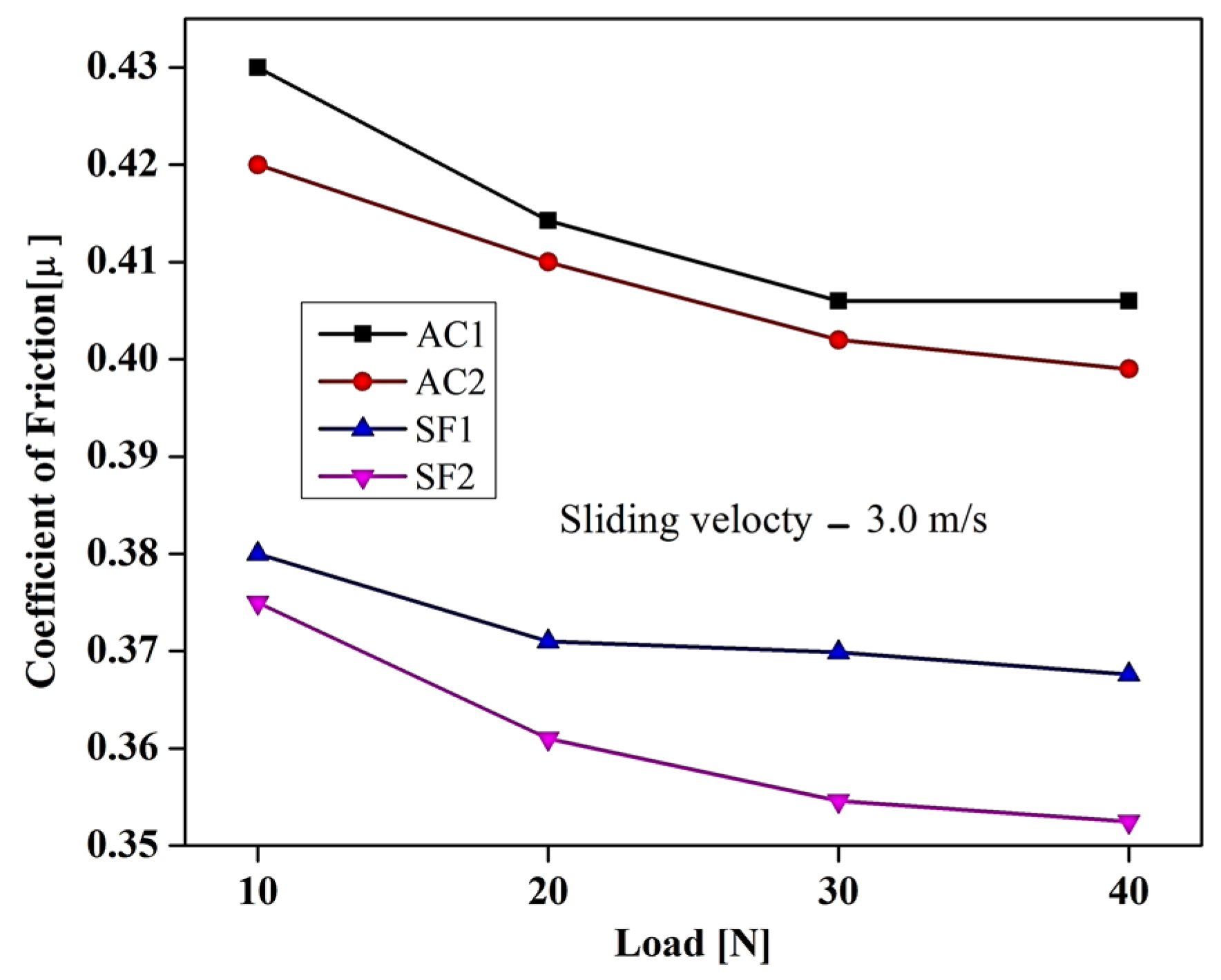
3.4.3. Variation of Friction Coefficient with Load at Constant Sliding Velocity

In Figure 8, the relationship between the coefficient of friction (µ) and the applied load at a sliding velocity of 3.0 ms−1 is presented. It was observed that the µ remained almost steady, with a slight decrease over time as the load increased. The results indicate that regardless of the composition, the SF alloys had a lower µ than did the AC alloys. The SF2 alloy in particular had the lowest µ. At a load of 10 N, the SF1 and SF2 alloys exhibited 7% and 4% less µ, respectively, compared to the AC alloys. At a high load of 40 N, the µ of the SF1 and SF2 alloys was 9% and 6% less than that of the AC1 andAC2 alloys, respectively. When the load is low, there is no metal-to-metal contact between the pin and counter surface. Instead, the behavior is influenced by the oxidation process and the adhesion of small protrusions on the contacting surfaces. As the load increases, the µ decreases slightly, which may occur because of metallic contact between the counter face and the pin. This contact leaves no room for imperfections and locks the surface contact area. The slight variation in the µ at higher loads may be attributed to the fact that all alloys contain more aluminum than the alloying elements. At higher loads, the aluminum matrix in the specimens and the counter face come in contact with each other, which determines the effective coefficient of friction.

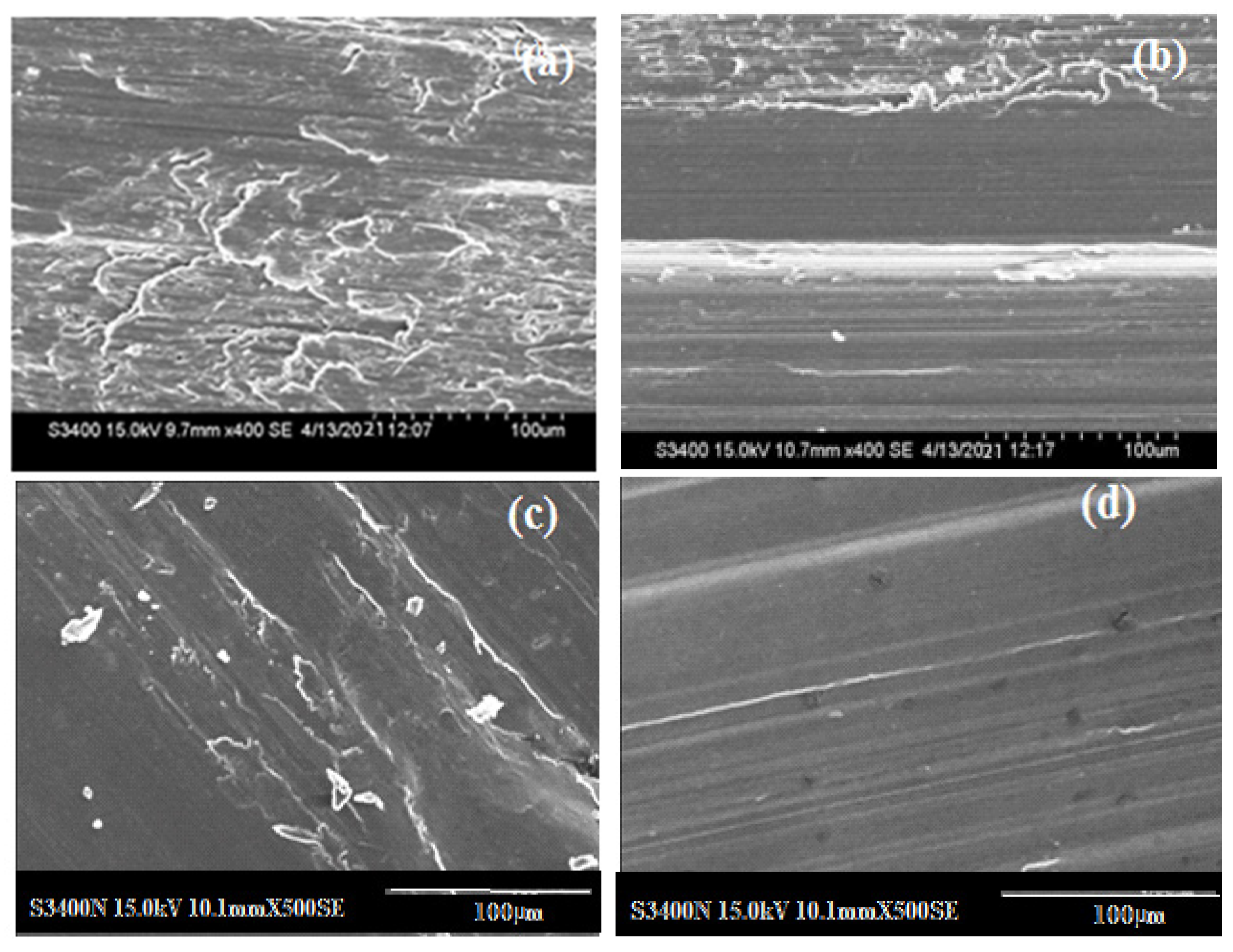
3.5. Topographical Features of Worn Surfaces

The worn surfaces of AC and SF alloys at a 40 N load and a sliding velocity of 3.0 ms−1 are as shown in Figure 9. The topography of the worn surfaces indicates that the binary alloys have suffered more damage than the ternary alloys. The worn surface of the AC1 alloy showed several features, including oriented overlapping flaky structures, wear scars, craters, the crass plastic flow of metal, metallic fracture of the ridges, and edge cracking (Figure 9a). The damaged surface also revealed evident signs of plastic deformation, along with adhesive wear. On the other hand, the AC2 alloy, as shown in Figure 9b, shows wide parallel grooves, compacted oxide patches, and a few discontinuous abrasive grooves on its worn surface. During the wear testing, the sliding of a soft pin surface against a hard disc caused two types of abrasive wear. The first type occurred when the pin penetrated the disc and created continuous parallel grooves. The second type occurred when hard intermetallic phases, such as Si and Al2Cu, were introduced between the sliding surfaces. This type of wear caused the formation of surface cavities due to debris detachment, which indicated delimitative wear on the surface layers. As a result, cracks were formed below the surface layers and grew until they joined together, forming plate-shaped particles that detached from the wear surface. In Figure 9c, it is observed that the worn surface of the SF1 alloy displayed a homogenous wear pattern. The surface was smooth, with fine abrasion grooves, a few small dimples, and some scoring marks that extended from end to end. Additionally, the surface showed white patches, indicating the early stages of oxide formation. On the other hand, in Figure 9d, we can see the worn surface of the SF2 alloy, which had small, homogeneous, and continuous grooves. The surface was smooth, with fine scoring marks, and it had no pits or dimples, indicating a low wear-rate [24].

4. Conclusions

The following conclusions may be drawn from the present study on AC and SF alloys:
  • The microstructure of the SF1 alloy consists of eutectic Si particles ranging from 3 to 7 µm, which are uniformly distributed in the Al-matrix. The SF2 alloy exhibited a uniform distribution of eutectic Si, Al2Cu, and Al-Si-Cu intermetallic phases in the equiaxed Al-matrix.
  • The micro hardness of the SF2 alloy has been improved by 8, 34, and 41% compared to that of the SF1, AC2, and AC1 alloys, respectively.
  • The SF2 alloy exhibits superior wear resistance to that of the SF1 and AC alloys under varying load and sliding velocity conditions. This improvement was attributed to the fine and uniform distribution of the Si and intermetallic phases and to the increased solid solubility. Specifically, at a 40 N load and a 1 ms−1 sliding velocity, the wear resistance of the SF2 alloy is 23, 47, and 62% higher than that of the SF1, AC2, and AC1 alloys, respectively. Similarly, when sliding at 3 ms−1, the wear resistance of the SF2 alloy is 21, 42and 52% higher than that of the SF1, AC2, and AC1 alloys, respectively.
  • The primary wear mechanism for the AC alloys under dry sliding conditions involved abrasion and adhesion, and for the SF alloys, it involved oxidation and abrasion. An increased load resulted in more wear due to the increased depth of penetration. However, at 40 N, for all sliding velocities, the AC alloys exhibited considerably higher wear loss throughout the sliding distance compared to that observed for the SF alloys. This was attributed to the softening of the wear pin at the high load, which accelerated both abrasive and adhesive wear at a 3.0 ms−1 sliding velocity.

Author Contributions

D.M.G.—obtained the mechanical, wear, phases of chemical compositions, microstructure, and hardness results and performed data processing; J.H., R.V.K. and K.R.—helped with the collection of data from the scientific literature review, organized the results obtained from the scientific community, and contributed to the discussion of the selected results; D.M.G., J.H., R.V.K., K.R. and D.G.P.—contributed to result interpretation and manuscript writing. All authors have read and agreed to the published version of the manuscript.

Funding

This research received no external funding.

Data Availability Statement

The data presented in this study are available within the article.

Acknowledgments

The authors gratefully acknowledge the financial support for this work from the Vision Group on Science and Technology (VGST), Government of Karnataka, Bengaluru, under the scheme VGST/K-FIST (LEVEL–I)/GRD-885.2. We would also like to express a sincere acknowledgement to Fundação para a Ciência e a Tecnologia (FCT), with Portuguese Government funds through the CQM Base Fund—UIDB/00674/2020 (DOI: 10.54499/UIDB/00674/2020) and the Programmatic Fund—UIDP/00674/2020 (DOI 10.54499/UIDP/00674/2020), and to the ARDITI-Agência Regional para o Desenvolvimento da Investigação Tecnologia e Inovação, through funds from Região Autónoma da Madeira-Governo Regional.

Conflicts of Interest

The authors declare no conflicts of interest.

Abbreviations

AC—As-cast; SF—spray forming/spray formed; SEM—scanning electron microscopy; µ—coefficient of friction; EDS—energy dispersive spectroscopy; VHN—Vickers hardness number.

References

  1. Awotunde, M.A.; Adegbenjo, A.O.; Obadele, B.A.; Okoro, M.; Shongwe, B.M.; Olubambi, P.A. Influence of sintering methods on the mechanical properties of aluminium nano composites reinforced with carbonaceous compounds: A review. J. Mater. Res. Technol. 2019, 8, 2432. [Google Scholar] [CrossRef]
  2. Md Ali, A.; Omar, M.Z.; Hashim, H.; Salleh, M.S.; Mohamed, I.F. Recent development in graphene-reinforced aluminium matrix composite: A review. Rev. Adv. Mater. Sci. 2021, 60, 801. [Google Scholar] [CrossRef]
  3. Abbasipour, B.; Niroumand, B.; Vaghefi, S.M.M.; Abedi, M. Tribological behavior of A356− CNT nanocomposites fabricated by various casting techniques. Trans. Nonferr. Metal. Soc. 2019, 29, 1993–2004. [Google Scholar] [CrossRef]
  4. Zhuo, X.; Zhang, Q.; Liu, H.; Hu, Z.; Zhang, P.; Jiang, J.; Ma, A.; Wu, Y. Enhanced tensile strength and ductility of an Al-6Si-3Cu alloy processed by room temperature rolling. J. Alloys Compd. 2022, 899, 163321. [Google Scholar] [CrossRef]
  5. Wu, Y.; Liu, C.; Liao, H.; Jiang, J.; Ma, A. Joint effect of micro-sized Si particles and nano-sized dispersoids on the flow behavior and dynamic recrystallization of near-eutectic Al–Si based alloys during hot compression. J. Alloys Compd. 2021, 856, 158072. [Google Scholar] [CrossRef]
  6. Liu, S.; Zhang, X.; Peng, H.L.; Han, X.; Yang, H.Y.; Li, T.T.; Zhu, L.; Zhang, S.; Qiu, F.; Bai, Z.H.; et al. In situ nanocrystals manipulate solidification behavior and microstructures of hypereutectic Al–Si alloys by Zr-based amorphous alloys. J. Mater. Res. Technol. 2020, 9, 4644. [Google Scholar] [CrossRef]
  7. Rahman, A.A.; Salleh, M.S.; Othman, I.S.; Yahaya, S.H.; Al-Zubaidi, S.S.; Zulkifli, K. Investigation of mechanical & wear characteristics of t6 heat treated thixoformed aluminium alloy composite. J. Adv. Manuf. Technol. 2020, 14, 1. [Google Scholar]
  8. Lantmann, R.V.; Mariante, A.M.S.; Pinheiro, T.V.; da Costa, E.M.; dos Santos, C.A. Microstructure, Hardness, and Linear Reciprocating Sliding Wear Response of Directionally Solidified Al–(2.5, 3.5, 4.5)Cu–(0.25, 0.50)Cr Alloys. Metals 2023, 13, 1178. [Google Scholar] [CrossRef]
  9. Mostafa, A.; Alshabatat, N. Microstructural, Mechanical and Wear Properties of Al–1.3%Si Alloy as Compared to Hypo/Hyper–Eutectic Compositions in Al–Si Alloy System. Crystals 2022, 12, 719. [Google Scholar] [CrossRef]
  10. Nama, H.A.H.A.; Esen, İ.; Ahlatcı, H.; Karakurt, V. Effect of Aging Heat Treatment on Wear Behavior and Microstructure Characterization of Newly Developed Al7075+Ti Alloys. Materials 2023, 16, 4413. [Google Scholar] [CrossRef]
  11. Kumar, P.; Wani, M.F. Friction and Wear Behaviour of hypereutectic Al-Si Alloy/Steel Tribopair under Dry and Lubricated Conditions. J. Tribologi. 2017, 15, 21. [Google Scholar]
  12. Jain, S.; Patel, M.; Kumar, V.; Samal, S. Effect of Si on phase equilibria, mechanical properties and tribological behaviour of Al-Cu alloy. Silicon 2023, 15, 1807–1820. [Google Scholar] [CrossRef]
  13. Alshmri, F.; Atkinson, H.V.; Hainsworth, S.V.; Haidon, C. Dry sliding wear of aluminium-high silicon hypereutectic alloys. Wear 2014, 313. [Google Scholar] [CrossRef]
  14. de Souza Baptista, L.A.; Paradelaa, K.G.; Ferreira, I. Amauri Garcia and Alexandre Furtado Ferreira. Mater. Res. Technol. 2019, 8, 1515. [Google Scholar] [CrossRef]
  15. Zheng, Y.; Xiao, W.; Ge, S.; Zhao, W.; Hanada, S.; Ma, C. Effects of Cu content and Cu/Mg ratio on the microstructure and mechanical properties of Al–Si–Cu–Mg alloys. J. Alloys Compd. 2019, 649, 291. [Google Scholar] [CrossRef]
  16. Timelli, G.; Fabrizi, A.; Vezzù, S.; De Mori, A. Design of Wear-Resistant Diecast AlSi9Cu3(Fe) Alloys for High-Temperature Components. Metals 2020, 10, 55. [Google Scholar] [CrossRef]
  17. Zeren, M.; Karakulak, E.; Gümüş, S. Influence of Cu addition on microstructure and hardness of near-eutectic Al-Si-xCu-alloys. Transactions 2011, 21, 1698–1702. [Google Scholar] [CrossRef]
  18. Alavandi, M.R.; Haider, J.; Goudar, D.M. Investigation of the influence of Ni and Cu additions on the wear behavior of spray formed Al-15Si alloy at elevated temperature. Silicon 2023, 15, 5963–5980. [Google Scholar] [CrossRef]
  19. Chen, W.C.; Wu, C.T.; Bor, H.Y.; Lee, S.L. Effects of Cu Content on Thermal Stability and Wear Behavior of Al-12.5 Si-1.0 Mg Alloy. J. Mater. Eng. Perform. 2013, 22, 3854. [Google Scholar] [CrossRef]
  20. Tash, M.M.; Mahmoud, E.R.I. Development of in-Situ Al-Si/CuAl2 Metal Matrix Composites: Microstructure, Hardness, and Wear Behavior. Materials 2016, 9, 442. [Google Scholar] [CrossRef] [PubMed]
  21. Shetty, R.; Gurupur, P.R.; Hindi, J.; Hegde, A.; Naik, N.; Ali, M.S.S.; Patil, I.S.; Nayak, M. Processing, Mechanical Characterization, and Electric Discharge Machining of Stir Cast and Spray Forming-Based Al-Si Alloy Reinforced with ZrO2 Particulate Composites. J. Compos. Sci. 2022, 6, 323. [Google Scholar] [CrossRef]
  22. Lee, E.; Mishra, B. Effect of solidification cooling rate on mechanical properties and microstructure of Al-Si-Mn-Mg alloy. Mater. Trans. 2017, 58, 1624–1627. [Google Scholar] [CrossRef]
  23. Patrick, S.G. Solidification in Spray Forming. Metallurg. Mater. Trans. A 2017, 38, 1520–1529. [Google Scholar] [CrossRef]
  24. Goudar, D.M.; Raju, K.; Srivastava, V.C.; Rudrakshi, G.B. Effect of copper and iron on the wear properties of spray formed Al–28Si alloy. Mater. Des. 2013, 51, 383. [Google Scholar] [CrossRef]
  25. Raju, K. Effect of Processing Techniques on the Microstructure & Wear Characteristics of Al-Si Alloys. Ph. D. Thesis, IIT(BHU), Varanasi, India, 2009. [Google Scholar]
  26. Li, H.; Cao, F.; Guo, S.; Jia, Y.; Zhang, D.; Liu, Z.; Wang, P.; Scudino, S.; Sun, J. Effects of Mg and Cu on microstructures and properties of spray-deposited Al-Zn-Mg-Cu alloys. J. Alloys Compd. 2017, 719, 89. [Google Scholar] [CrossRef]
  27. Cai, W.D.; Lavernia, W.J. Low pressure spray forming of 2024 aluminium alloy. Mat. Sci. Eng. A 1997, 8, 226–228. [Google Scholar]
  28. Lavernia, E.J.; Grant, N.J.; Ando, T. Rapidly Solidified Materials; Lee, P.W., Carbonara, R.S., Ohio, Eds.; American Society for Metals: Metals Park, OH, USA, 1986; p. 29. ISBN 978-0871702241. [Google Scholar]
  29. Gwidon, W.S. Wear—Materials, Mechanisms and Practice; John Wiley & Sons Ltd.: Chichester, UK, 2006; ISBN 978-0-470-01628-2 (HB). [Google Scholar]
  30. Lin, L.; Zhao, Y.; Hua, C.; Schlarb, A.K. Effects of the velocity sequences on the friction and wear performance of PEEK-based materials. Tribol. Lett. 2021, 69, 68. [Google Scholar] [CrossRef]
  31. Greenwood, J.A. Metal transfer and wearFront. Mech. Eng. 2020, 6, 62. [Google Scholar] [CrossRef]
  32. Bidmeshki, C.; Abouei, V.; Saghafian, H.; Shabestari, S.G.; Noghani, M.T. Effect of Mn addition on Fe-rich intermetallics morphology and dry sliding wear investigation of hypereutectic Al-17.5% Si alloys. J. Mater. Res. Technol. 2016, 5, 250. [Google Scholar] [CrossRef]
Figure 1. Flow diagram depicting the details of spray forming of the Al-12.6Si alloy.
Jcs 08 00088 g001
Figure 2. AC1 alloy (a) optical microstructure; (b) EDX spectrum.
Jcs 08 00088 g002
Figure 3. SF1 alloy (a) optical microstructure; (b) EDX spectrum.
Jcs 08 00088 g003
Figure 4. SEM microstructure of the AC2 alloy.
Jcs 08 00088 g004
Figure 5. SF2 alloy’s (a) SEM microstructure; (b) EDX spectrum.
Jcs 08 00088 g005
Figure 6. The variation in the wear rate of the AC and SF alloys as a function of load and sliding velocity (a) 1.0 ms−1; (b) 2.0 ms−1; (c) 2.5 ms−1; and (d) 3.0 ms−1.
Jcs 08 00088 g006
Figure 7. Variation of wear rate with sliding velocity at a load of (a) 10 N; (b) 20 N; (c) 30 N; (d) 40 N.
Jcs 08 00088 g007aJcs 08 00088 g007b
Figure 8. Coefficient of friction versus applied load at a sliding velocity of 3.0 ms−1.
Jcs 08 00088 g008
Figure 9. SEM micrographs of worn surfaces of (a) AC1, (b) AC2, (c) SF1 and (d) SF2 alloys.
Jcs 08 00088 g009
Table 1. The details of the composition of the experimental alloys (wt.%).
AlloySiFeMnMgCuAl
Al-12.6Si (AC1)12.60. 30.060.240.04Bal.
Al-12.6Si-2Cu (AC2)12.60. 40.020.142.06Bal.
Table 2. Details of process parameters for spray forming.
VariableValue
Melt superheat150 °C
Melt rate2.8 kg/min
Gas pressure0.55 MPa
Diameter of nozzle4.0 mm
Deposition distance400 mm
Table 3. Porosity values of spray-formed alloys.
DetailsSF1 AlloySF2 Alloy
Theoretical density (g/cm3)2.652.65
Density before hot pressing (g/cm3)2.172.33
Density after hot pressing (g/cm3)2.462.64
Porosity before hot pressing (%)1816
Porosity after hot pressing (%)75
Table 4. Phase composition of the AC ternary alloy obtained by EDX analysis.
EDX SpotsPhaseAl-KFe-KSi-KCu-K
Spot 1Q-Al74Si9Cu10661825
Spot 2θ-Al2Cu670.0231
Spot 3α-Al990.20.8 0
Spot 4Si10.099 0
Table 5. Phase composition of SF2 alloy obtained by EDX analysis.
EDX SpotsPhaseAl-KSi-KFe-KCu-K
Spot 1—SiAl48Si51475012
Spot 2—Q-phaseAl93Si6Cu1.990715
Spot 3—α(Al)Al92Si193511
Table 6. Hardness values of the AC and SF alloys.
AlloyHardness (VHN)
AC143 ± 4.1
AC248 ± 3.2
SF167 ± 5.1
SF273 ± 4.5
Disclaimer/Publisher’s Note: The statements, opinions and data contained in all publications are solely those of the individual author(s) and contributor(s) and not of MDPI and/or the editor(s). MDPI and/or the editor(s) disclaim responsibility for any injury to people or property resulting from any ideas, methods, instructions or products referred to in the content.

