1. Introduction
The history of the birth of aerated concrete dates back to 1923, when the Swedish architect Axel Eriksson developed a technology for hardening blocks in autoclaves using hot steam and started the industrial production of products from the so-called aerated concrete. In Poland, the first experimental production of aerated concrete was launched in 1949, and industrial production began in July 1951. This year was a breakthrough in wall masonry technology, and aerated concrete has become one of the most popular materials for constructing structural walls in single-family housing due to the low specific weight of aerated concrete and because it allows for reducing the consumption of raw materials used for the supporting structure of the building. At the same time, it is possible to increase the number of floors of the same height by reducing the thickness of the ceilings or increasing the concrete class [
1,
2,
3,
4].
The term autoclaving is related to the process taking place in hermetically sealed autoclaves heated with fuel. There are two types of materials resulting from hydrothermal treatment: autoclaved sand-lime bricks and autoclaved concrete. Both in the case of AAC and silicates, the basic substrates used during their production are lime, sand and water (cement is also added to cellular concrete). The use of lightweight concrete, i.e., cellular concrete, is particularly important in the era of so-called development and ecological sustainable construction, which has its origin in the American continent. The production of aerated concrete is also based on two technologies: sand technology and ash technology (
Table 1).
Naturalness and environmental friendliness means the content of harmful substances in the raw material. This is also important due to modifications of construction materials, including waste materials. All building materials of mineral origin contain natural radioactive elements, of which the following are important due to the level of natural ionizing background radiation in the residential environment: potassium K-40, elements of the uranium–radium series and thorium series, radioactivity coefficients f
1 and f
2 and the radiation dose [
6,
7]. The chart below shows the levels of radioactive elements in sample construction materials. The best materials turn out to be aerated concrete and silicate bricks. In Poland, a systematic study of natural radioactivity of building products, including cellular concrete, has been carried out since 1980 (
Table 2) [
1].
Furthermore, cellular concrete poses no health risk to people permanently residing in rooms made of this material. Under simulated tropical climate conditions, the concrete has demonstrated complete resistance to bacteria, mold and fungi [
1].
The first supporter of changes and conscious development in every industry sector was Prof. Herman Daly (expert, eco-economist of the World Bank (World Bank Economist) [
9,
10,
11]. Aerated concrete (light autoclaved concrete) has a compressive strength of 2–6 MPa [
1]. The tests included aerated concrete modified with high-impact polystyrene, commonly known as HIPS [
12,
13]. HIPS high-impact polystyrene is a polymer thermoplastic, which is obtained by block-suspension polymerization of styrene with the addition of synthetic rubber. As a result of polymerization, fine particles of polybutadiene remain in the polystyrene male, changing its physical and mechanical properties [
14].
Autoclaved aerated concrete (
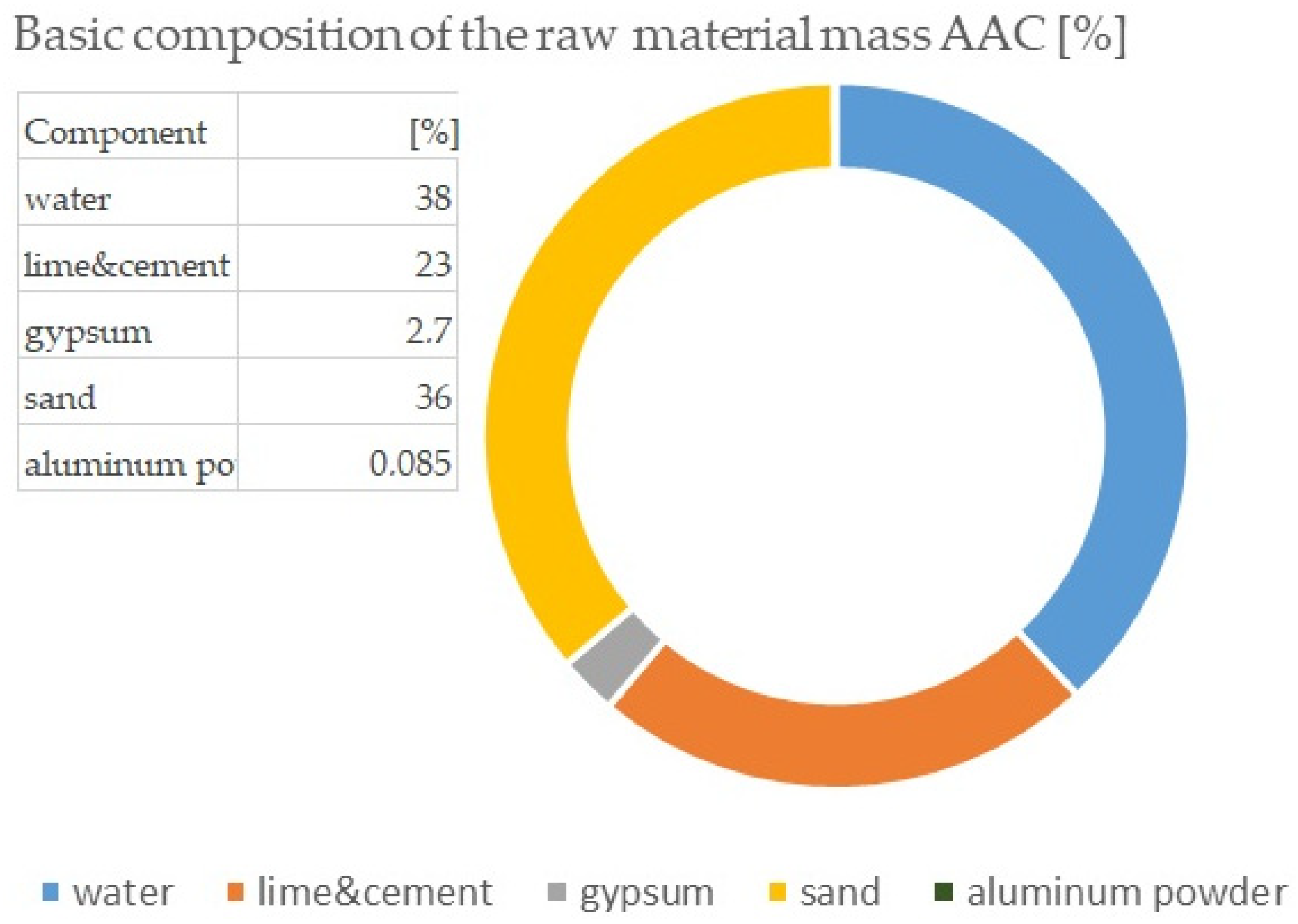
Figure 1) is a universal material known around the world. Over the years, many AAC production technologies have been developed, which use widely available raw materials available in a given country to obtain it, although they are usually sand, cement, calcium carbonate, gypsum, aluminum powder or aluminum paste, and as a blowing agent, water. Due to all the reactions occurring in the process of producing autoclaved aerated concrete, the raw materials used for production should consist mainly of calcium oxides CaO and silicon dioxide SiO
2 (
Figure 2). Aerated cellular concrete is a very porous material. Its specific texture is obtained using a blowing agent, and aluminum powders are most often used for this purpose and are fed into production in the form of a water suspension [
15,
16].
Table 1 shows the results of the elemental composition of aerated concrete (XRF analysis) of two samples: RD1—ACC concrete (
Figure 1) and RD2—ACC concrete with HIPS. Formula (1) shows the course of chemical reactions occurring in the hydration process and production of aerated concrete. The analysis included four samples: R1 (traditional aerated concrete) and aerated concrete with the addition of HIPS: R2, R3, R4 [
1]. Due to the fact that this is a continuation of research on the porosity of ACC concrete modified with waste material and for economic reasons, only samples R1—traditional—and R2—modified with HIPS (10%)—are included in the presented article [
16].
Table 3 shows the first differences in the elemental structure of traditional and modified HIPS autoclaved concrete. However, due to its temperature resistance, HIPS acts as a mass modifier, i.e., an additive, and mainly affects the physical and mechanical properties of the tested material.
Aerated concrete is a highly porous material and, therefore, has good thermal insulation properties, although its strength is not high, but it is sufficient for the construction of single-family buildings (standard 2–6 MPa). After weighing the ingredients of the raw material, mixing and then pouring the concrete mixture into the molds, a series of chemical reactions begin, leading to the formation of a concrete block. The most important of them is the reaction of the aluminum powder, causing the mass to rise. A necessary condition for this reaction to occur is to ensure a sufficiently high pH of the mixture, which is achieved by the formation of calcium hydroxide Ca(OH)
2 in the process of slaking quicklime, as well as in the process of hydration of the cement components: alite C
3S and belite β-C
2S [
16,
17,
18,
19,
20]. Typically, autoclaved materials produce tobermorite as the dominant phase and according to Matsui and all C-S-H, hydroxylellestadite and katoite were clearly observed as intermediates [
19]. Modifications of the raw material mass affect the porous structure of the basic material and its phase transformations. Phase transformations are related to the so-called hardening of the binder, i.e., the formation of a crystal structure. C-S-H this phase is responsible for 70–80% of concrete strength. It is an amorphous phase that crystallizes over the years (concretes from the times of the Roman Empire crystallize to this day). At the moment of crystallization of the C-S-H phase, its specific surface changes (decreases) creating free spaces in the pores, which allows, for example, water to interfere with the concrete structure, which in turn leads to the destruction of the concrete structure (or other building materials). In autoclaved materials, apart from the amorphous C-S-H phase, a large percentage of the tobermorite phase is present. Toberomrite (C-S-H I (tobermorite) and C-S-H II (jennite) are hydrated calcium silicates with a crystalline structure (formed as a result of high temperature and/or pressure in the C-S-H phase [
1,
20]. Acceleration of the formation of tobermorite under the influence of the addition of Al is clearly observed. However, the addition of Al has no effect on the dissolution rate of quartz. In the system containing Al, two paths were also observed, via C-S-H and katoite. These results suggest that the structure of the initially formed C-S-H is important for subsequent tobermorite formation reactions [
20]. Due to the low value of compressive strength and the need to recycle waste materials, cellular concrete was modified with an HIPS substrate. The construction sector has a significant impact on environmental costs; this part of human activity contributes almost 36% to the generated waste [
21,
22].
The subject of the research are materials formed as a result of hydrothermal treatment, in this case, cellular concretes, both traditional and modified with plastics (HIPS). An aspect of the research is the analysis of the porous structure of cellular concretes using computed tomography and the analysis of the phase structure of cellular concretes modified with HIPS—high-impact polystyrene [
12,
23,
24]. Due to the excessive use of natural resources and ongoing climate change, further technological and material construction restrictions are being introduced regarding both the design and construction of building partitions. In many cases, the analysis of building partitions and joints in terms of construction, material and manufacturing technology issues does not raise any objections at the design stage. However, knowledge of the thermal–humidity (physical) parameters related to the exchange of heat and moisture allows you to avoid many design and construction defects and ensure appropriate parameters of the interior microclimate during use (appropriate temperature, humidity and cleanliness of the internal air) [
25]. Using waste for energy recovery and material recycling helps address the global waste challenge and enables circular economy solutions [
26]. Compressive strength plays the most important role in construction materials, because the construction material should carry the load that will rest on it (ceilings, roof trusses and roof covering). Currently, an important parameter is the thermal insulation properties of building materials [
27].
The strength of construction materials is directly related to their porosity. Important components of the concrete structure are the air pores created by aeration and the air voids created during mixing and placing concrete. Assessment of the distribution, size and shape of pores has a decisive impact, among others, on the inference of the durability of concrete. As a result of the action of the air-entraining agent, large-sized air pores are created from 10 to 1250 μm (optimally < 300 μm). In addition to those mentioned, there are pores in the concrete structure (large pores > 500 μm), created for technological reasons (e.g., excess mixing water), and capillary and gel pores. Pores accidentally formed as a result of an inappropriate selection of ingredients or inappropriate technology of mixing and placing the concrete mixture are harmful to the strength and tightness of the concrete and its frost resistance. Analysis of the air void system in hardened concrete allows you to determine the expected frost resistance of the material. Assessment of the effectiveness of the aeration treatment is made on the basis of the results of diagnostic tests. The basic method of examining the structure of concrete is a qualitative image analysis of its structure, followed by computer image analysis, leading to quantitative results. One of the modern methods used to analyze the pore skeleton is tomographic analysis (micro-CT). Computed tomography (CT analysis) is a type of X-ray spectroscopy that allows us to obtain tomographic images (cross-sections) of the examined object and then presents its spatial image (3D) from many flat shots (2D) taken in different positions [
13]. Tomographic images contain information about the location and absorbing features of the object and are further used to reconstruct spatial data. Any difference in the material inside an object, any change in its density or pores, can be imaged and measured [
28].
Conventional CT maintained a strong position in life science, low-resolution high-energy CT became widespread in industrial quality control, and micro-CT has enjoyed a boost in interest from the materials science research community in the past decade. The key reasons behind this are the versatile, nondestructive nature of micro-CT as a characterization method, also offering in situ and in operando possibilities, and the fact that micro-CT has become indispensable in developing and verifying computational material models as well [
29].
Guangyu Lei and his team used computed tomography to analyze concrete porosity in the context of strength. In their article, they wrote that due to the plasticity of concrete, its compressive strength and durability, it is widely used in construction, but it is susceptible to static loads that change slowly and dynamic loads that change quickly, which thus change the way and the risk of destroying the structure of this material. Also, Raphael J.M. and his research team [
30] described that the dynamic strength of concrete is about 30% higher than the static strength, and the dynamic tensile strength is about 10% higher than the dynamic compressive strength. The computer tomography method, as a non-destructive method, allowed for the determination of changes occurring in concrete under the influence of the loads to which the structure is exposed [
31].
Computed tomography (CT) analysis is a non-destructive technique based on X-ray absorption, allowing for the visualization of the internal microstructure of the material. The field of application is very wide. It is a technology known in medicine due to its great advantages, but also very useful in other fields. Computed tomography is used in paleontology to study the internal structure of the bones of ancient hominids. In addition, this technology is used by engineers to analyze the microstructure of materials. This technology is very useful for the study of, e.g., new and modern concretes and those reinforced with fibers and waste materials [
32]. The tests were supplemented with an analysis using a scanning electron microscope and mercury porosimetry [
11].
The presented article is a conference article which is a continuation of the research contained in the article entitled “Insulated Autoclaved Cellular Concretes and Improvement of their Mechanical and Hydrothermal Properties”, which primarily covers the possibility of using computed tomography to determine the skeleton of porous cellular concrete (which is a low-strength concrete of 2–6 MPa, depending on the class and quality of the ingredients), in order to properly select potential modification with waste materials, which are aimed at increasing its strength and improving resistance to loads acting on the structure [
33].
2. Materials and Methods
The basic material was autoclaved aerated concrete, while the mass modifier was a filler in the form of HIPS. The tests were carried out based on the standard PN-EN 771-4 for masonry elements made of ACC concrete “Requirements for masonry elements—Part 4: Masonry elements made of autoclaved aerated concrete”. Other tests performed included: calorimetry, microstructure using a scanning electron microscope (SEM) and porosity analysis using computed tomography (
Table 4). Porosity analysis using micro-CT was compared with the mercury porosimeter examination included in the previous research part of aerated concrete samples.
The tests were carried out on cubic samples (
Figure 3) with a cubic diameter and sides of 100 mm, produced in semi-industrial conditions at the AAC plant. Concrete, variant 500, was produced using slow-setting technology silicate technology (SW), which involves the production of a suspension of ground quartz sand and water with quicklime and unground cement as a binder. Individual ingredients, i.e., lime, gypsum, dosed gradually by mixing with sand and additional water. Blowing and surfactant substances were prepared in the form of a powder suspension. The composition of the mass was as follows:
- ⇨
sand and gypsum together = approximately 72% of the product weight;
- ⇨
cement and lime = about 20%;
- ⇨
water = 7%.
At this stage, the appropriate amount of additives was added. Percentage of additives in relation to sand and gypsum in individual samples were 10%, 20% and 30% HIPS. After mixing the ingredients, the product produced was placed in tripartite forms. There were forms stored for three hours in pre-ripening chambers at 60 °C. During this process, the samples achieved sufficient compressive strength for removal from the mold and placed in autoclaves for hydrothermal treatment for about 13 h at 191 °C and steam pressure 1.2 MPa [
10,
11].
The HIPS modifier, i.e., high-impact polysterene, is a modification of polystyrene (PS), which is created by adding butadiene rubber. Due to its properties, HIPS is used in advertising, the food industry and industry. Due to the need to recycle waste materials and search for methods of their disposal, HIPS was used in autoclaved materials, i.e., aerated concrete (AAC—autoclaved aerated concrete/ACC—autoclaved cellular concrete) [
19,
20]. The table (
Table 5) below presents the basic properties of high-impact polystyrene (HIPS).
Samples R1 (traditional) and R2 (modified 10% HIPS) were analyzed due to the lack of chemical interactions. Additionally, the following analyses were included in the work:
- -
Physico-mechanical properties (
Table 6);
- -
XRF analysis—elemental composition;
- -
Analysis of the microstructure using a scanning electron microscope (SEM);
- -
Analysis of porosity of materials resulting from hydrothermal treatment: computed tomography method.
Micro-CT analysis was performed with a Nikon XT H 225 ST CT scanner (day of production: November 2018, UK). The CT scan was conducted with a reflection lamp (reflection target). The maximum capacity of this lamp is 225 kV and 225 W. The scan was made without a filter at 180 kV and 139 µA current. The exposure time was 250 ms. In total, 4476 projections were made and assembled into a 3D model. Each projection was generated with 4 frames per projection. The size of the voxel, i.e., the resolution, was 15 μm. All parameters were selected experimentally to ensure the best image quality. During the CT scan, the pores were determined using the porosity/inclusions analysis tool in VG Studio Max [
11]. Porosity research was performed using a QUANTACHROME ULTRAPYC 1200e helium pycnometer (Micromeritics Instrument Corporation, Norcross, GA, USA) on irregularly shaped samples weighing approximately 10–25 g. The helium pycnometer used in this test is a fully automated piece of equipment [
11,
20].
The photos presented in the article were taken on three kind of scanning electron microscope analyses (QuantaFEG, FEI Company, Hillsboro, OR, USA) [
11].
3. Results
The tests were carried out using fluorescence X-ray analysis, mercury porosimetry, CT computed tomography and SEM analysis. Fluorescence X-ray analysis was performed to check the chemical composition of the sample undergoing modification. The analyses were based on two samples, R1 and R2. The weight of samples RD1 and RD2 was 2 g, and the chemical formula was: C
38H
76N
2O
2, which means that the chemical composition was not disturbed. Computed tomography and measurements of external and internal geometry were performed using the device Nikon XT H 225 ST computed tomography. The industrial CT scanner was designed for non-surface analysis and visualization studies that provide insight inside the material being examined. The test is especially designed for specimens that are too large or heavy for other systems with a similar measurement range. The system can be equipped with three types of sources: reflective 225 kV, transmissive 180 kV, and rotary 225 kV. Micro-CT analysis enabled measurements of the external and internal geometry of AAC with HIPS. The tests showed the presence of pores with a size of 0.1 ÷ 100 μm, and the volume of voids in the material was estimated at approximately 50% (RD1 52.53%) and around 47% for ACC with HIPS (RD2 47.33%) [
1], while the average porosity of three samples, R2, R3, R4, was 52.52% [
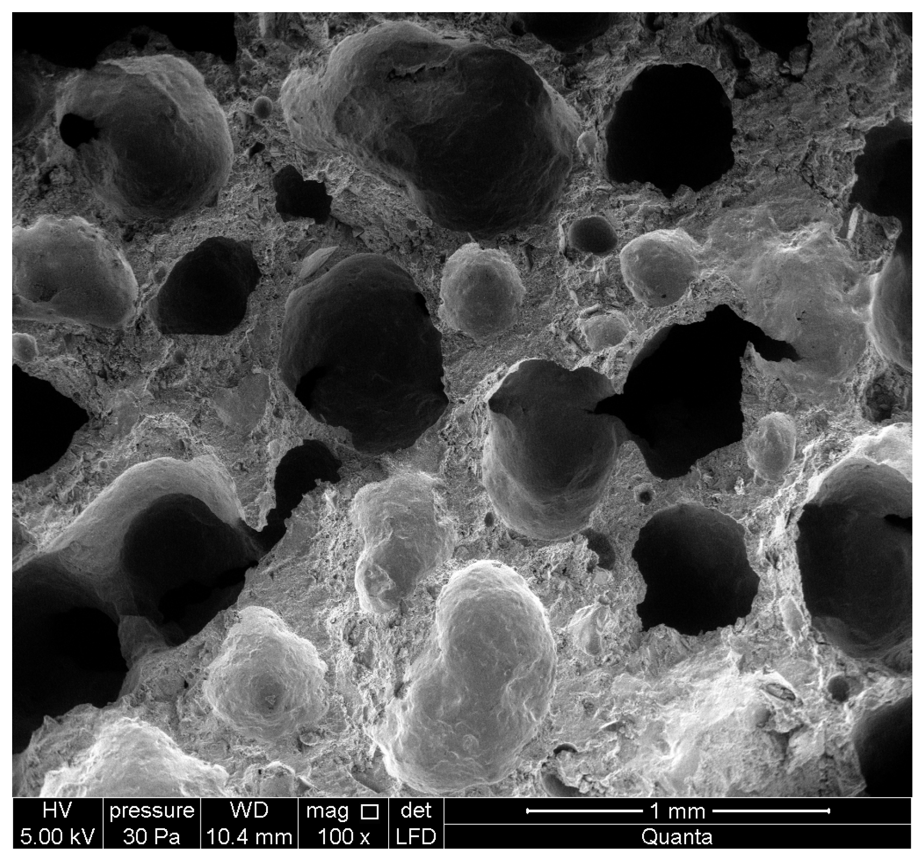
1]. The photos (
Figure 4,
Figure 5,
Figure 6 and
Figure 7) were taken using an SEM microscope (FEI Company). In aerated concretes, similarly to autoclaved bricks due to hydrothermal conditions, the C-S-H phase and crystalline tobermorite (
Figure 4 and
Figure 5) are formed, often called the C-S-H (I) phase. Photo
Figure 6 shows an image of the porosity of aerated concrete, while
Figure 7 shows the EDS spectrum, i.e., analysis of the elemental composition of ACC concrete.
Tobermorite takes the form of sheets and is a phase formed at a temperature higher than 70 °C with a low binder content. A higher binder content favors the formation and crystallization of the C-S-H phase towards jennite, i.e., C-S-H (II) [
1,
7].
Measuring the rate and amount of heat released using an isothermal calorimeter is a tool for assessing the hydration kinetics of cement composites, slurries, mortars and concretes, especially since research indicates that there is a strong correlation between heat hydration and compressive strength after 28 days of hardening of Portland cement [
24]. The use of modifiers in the form of industrial waste or processed plastics, despite potential ecological and economic benefits, must be carried out with comprehensive research in a long-term general perspective, i.e., variability in the physicochemical properties of the waste, and the influence of the modifier on hydration processes and on properties of the raw material mass as the final, hardened material intended for exploitation. This type of research is helpful, among others, in predicting the long-term properties of a composite.
Calorimetry and thermal analysis (
Figure 14) are used in virtually every one of the above-mentioned directions, mainly in comparative studies of hydration and its kinetics and the resulting products depending on the composition of the binder and its fineness and ratio water/cement, temperatures, etc. Isothermal calorimetry allows you to track the development of the heat of hydration (J/g) as well as the heat release rate (J/g/h) of cement materials as a function of time. Isothermal condition allow you to maintain a constant temperature during the test. An advantage of this method is the high precision of the measuring instrument compared to other semi-adiabatic or adiabatic methods [
25]. The binder hydration process consists of five stages: a rapid initial period, an induction period, a period of increasing the reaction rate, and a delay and deceleration stage. The calorimetric measurement results for samples R1 and R2 with the modifier show that the hydration process in both cases is gradual and even. The addition of HIPS does not affect changes in the binder hydration process.
Density tests for aerated concrete samples were carried out using a QUANTACHROME ULTRAPYC 1200e helium pycnometer on samples with an irregular shape and weighing approximately 10–25 g.
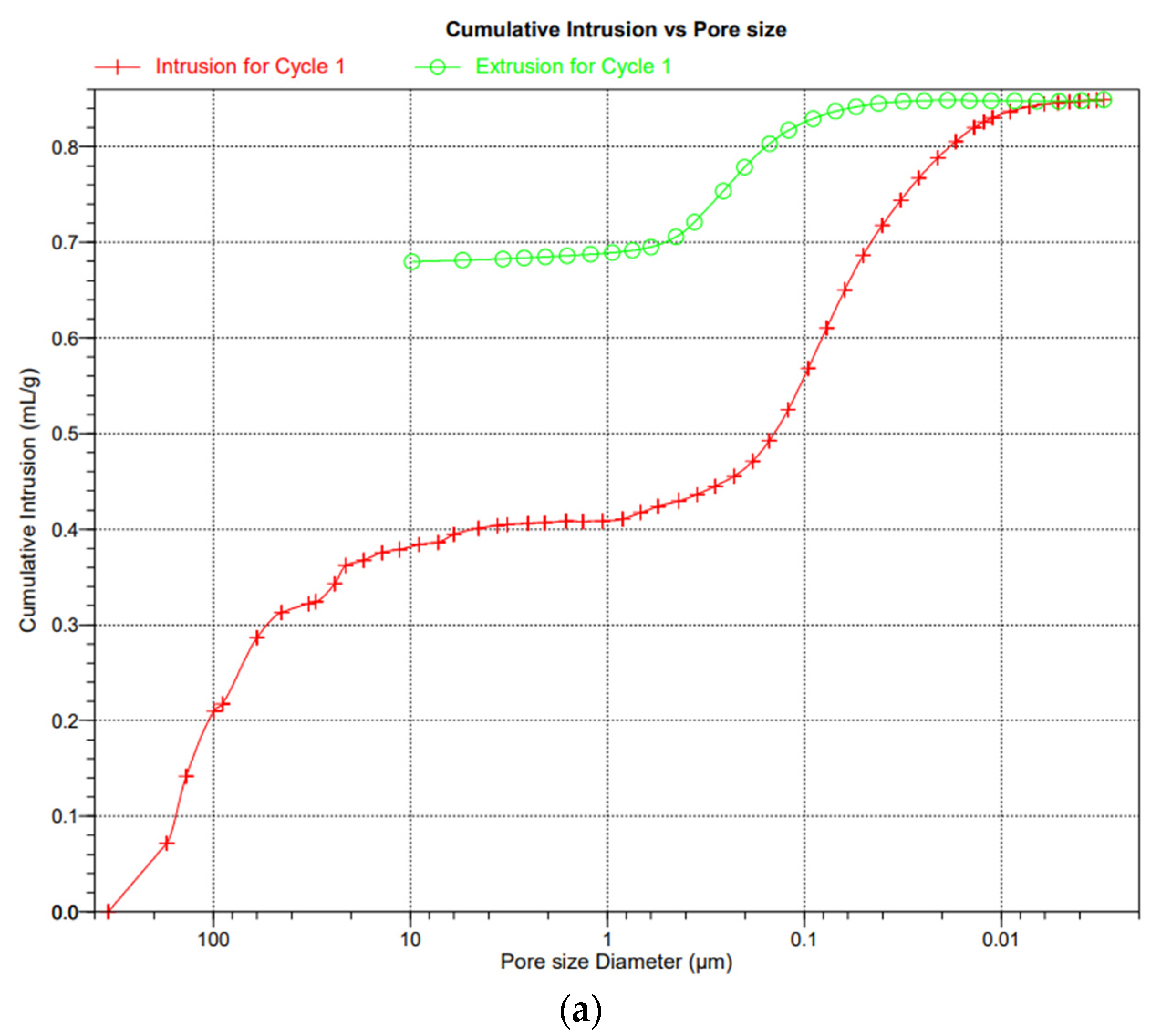
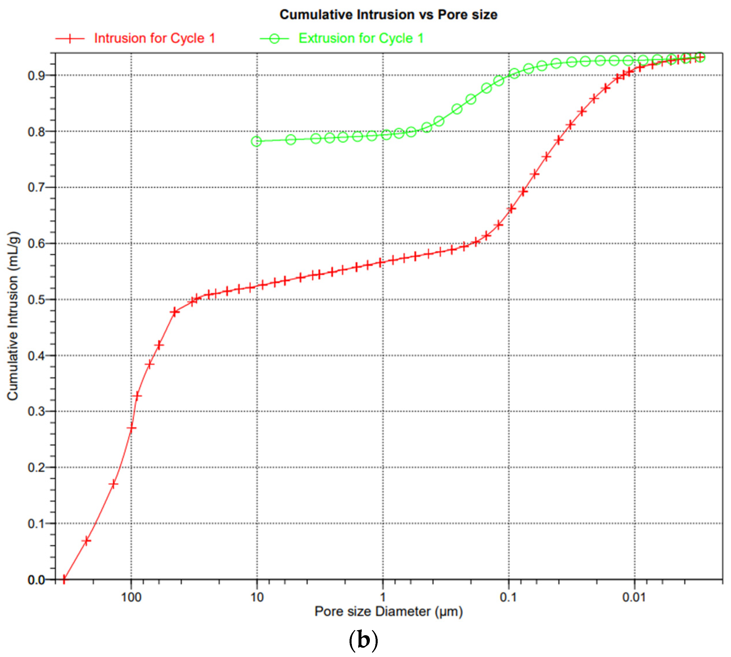
The graphs in
Figure 15a,b show a similar course of the curves, so the use of an additive in the form of plastic waste has a positive effect, especially since the strength of the modified material increased to 4.70 MPa from the initial 3.35.
Graphs
Figure 16 and
Figure 17 show the diameter and size distribution and arrangement of pores in traditional aerated concrete (R1—green curve) and modified HIPS (R2—red curve, R3—purple curve, R4—blue curve). As can be seen from the graphs, the curves have similar arrangements and pore arrangements. The porosity and connection of the base material, i.e., sand and binder with HIPS, are also influenced by technological factors, i.e., mixing and pressing of the raw material, and this may also lead to anomalies. The charts come from the publication in which the discussion and research on the porosity and properties of HIPS-modified aerated concrete began [
1].
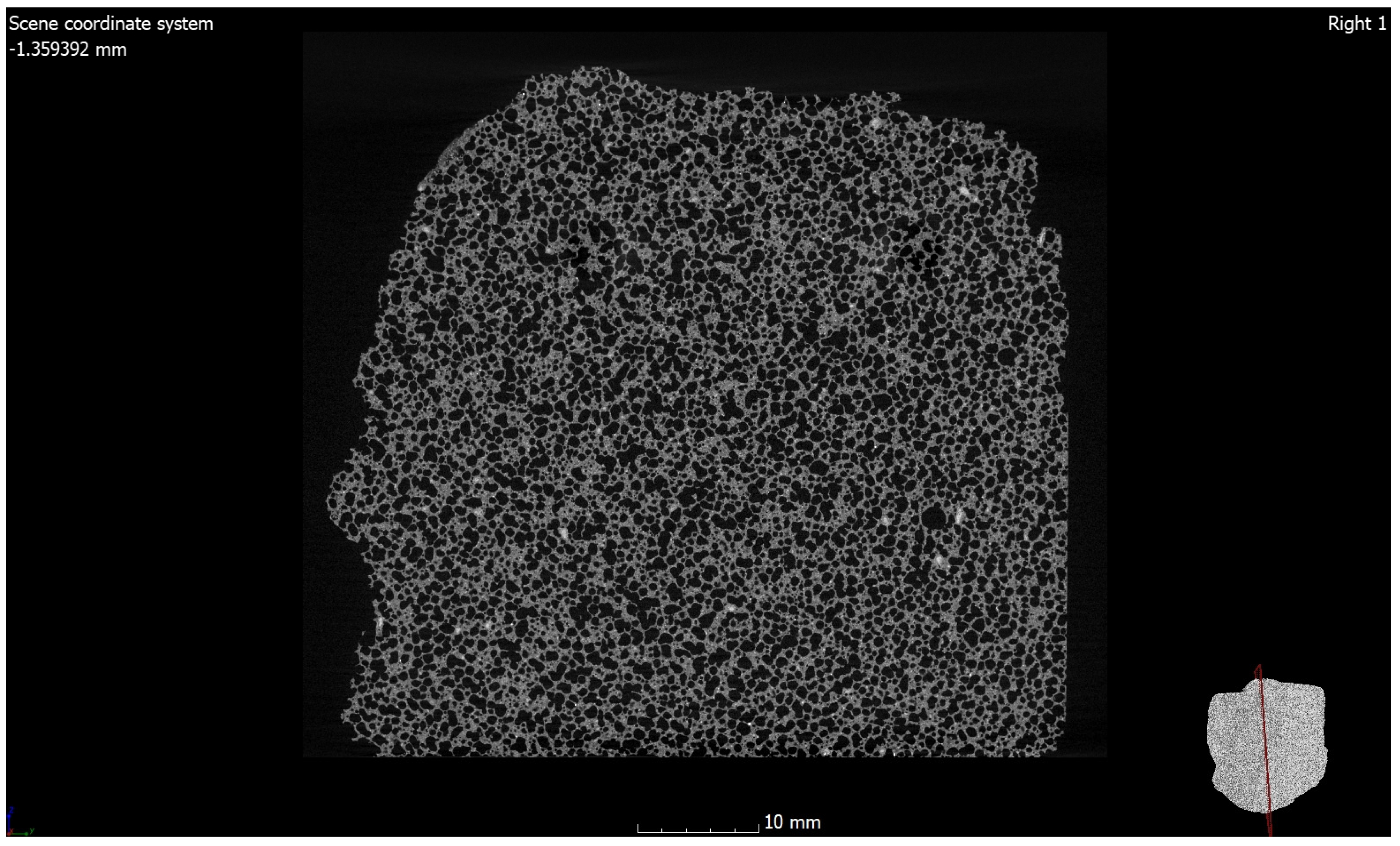
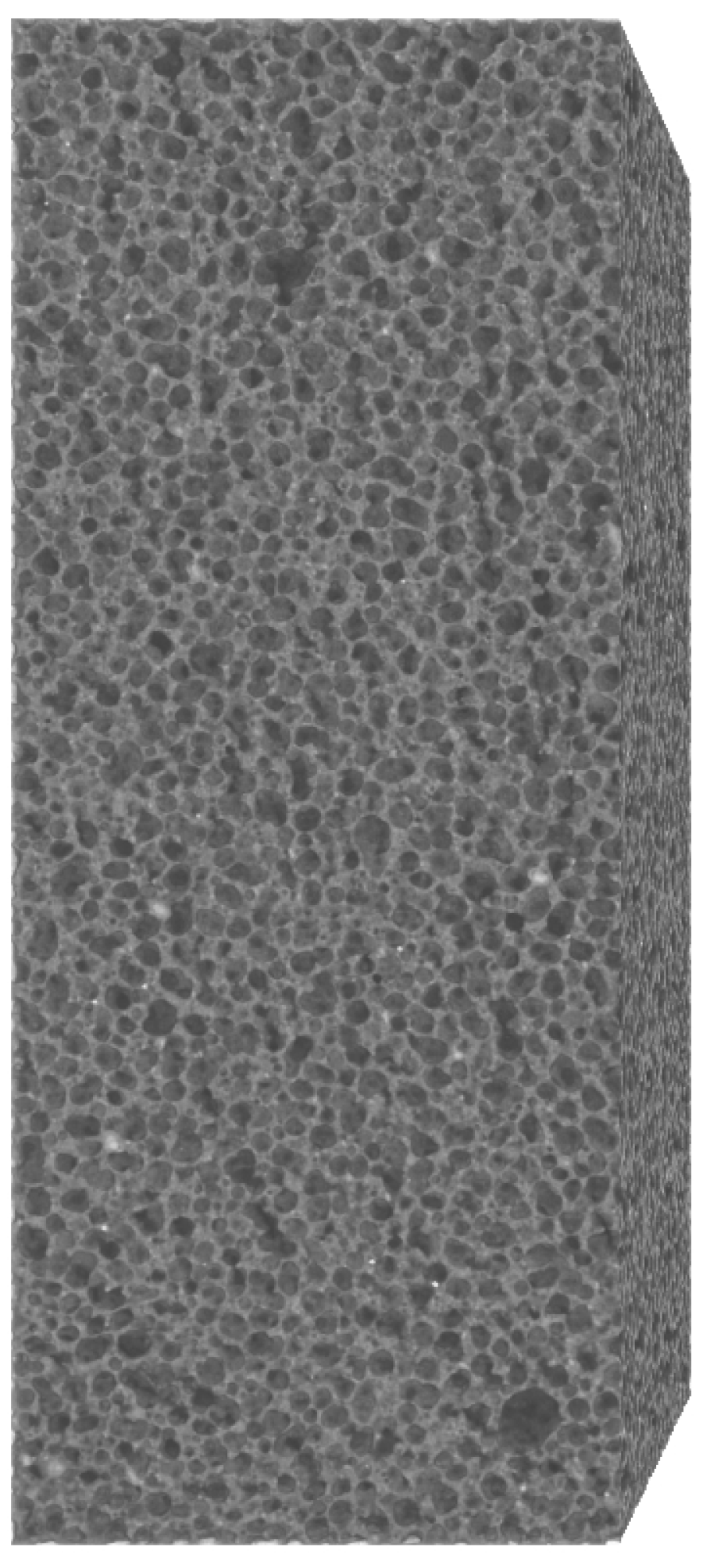
Photographs
Figure 18,
Figure 19,
Figure 20,
Figure 21,
Figure 22,
Figure 23,
Figure 24 and
Figure 25 show images from a computed tomography scanner, respectively:
Figure 6,
Figure 7,
Figure 8,
Figure 9,
Figure 10,
Figure 11 and
Figure 12 show the ACC (AAC) sample, and
Figure 13 and
Figure 14 show the ACC (AAC) with HIPS.
Table 7 shows the results of computed tomography porosity and the strength of samples RD1 and RD2.
The photos in
Figure 21,
Figure 22 and
Figure 23 show the shapes of closed and open pores in ACC concrete with HIPS. Photo
Figure 21 shows an image of the basic material (raw material mass). The photo
Figure 22 shows an image of the microstructure of the material with pores (red and blue colors are closed and open pores—total amount) and the basic material (raw material—gray). Photo
Figure 23 show an image of the pore skeleton without raw material.
4. Discussion and Conclusions
There are several methods for measuring porosity, including mercury porosimetry, the Archimedes method, and one of the newer methods considered to be non-destructive, i.e., computed tomography. Because of this method, it is possible to analyze the material at various time intervals and control changes in the microstructure and structure of the material, as well as possible changes in porosity occurring during the natural use of the material (pores may be destroyed and the number of closed and open pores in the material may change).
The most important study that we wanted to present was the analysis of porosity using computed tomography to illustrate the content of open and closed pores in the modified material, which is aerated concrete. Computed tomography and measurements of external and internal geometry were performed using the device Nikon XT H 225 ST computed tomograph. The results from the content of air voids in the autoclaved concrete sample were on average 52.53% for sample RD2 with HIPS.
A beneficial research aspect would be further analysis of the results and re-checking of porosity in the next 12, 24 and 36 months due to the fact that the amorphous phases present in the structure of the material crystallize under the influence of external factors, e.g., temperature.
The Archimedes method [
34] will be presented in an article reviewing various porosity testing methods for traditional and modified aerated concrete and determining the differences and accuracy of porosity measurements and the costs associated with the use of individual methods.


