
A Review on the Recent Trends in Forming Composite Joints Using Spot Welding Variants


1
School of Civil and Mechanical Engineering, Curtin University, Bentley, WA 6102, Australia
2
Engineering Institute of Technology, West Perth, WA 6005, Australia
*
Authors to whom correspondence should be addressed.
J. Compos. Sci. 2024, 8(4), 155; https://doi.org/10.3390/jcs8040155
Submission received: 8 March 2024
/
Revised: 12 April 2024
/
Accepted: 17 April 2024
/
Published: 19 April 2024
(This article belongs to the Special Issue Metal Composites, Volume II)
Abstract
:Traditional resistance spot welding (RSW) has been unsuccessful in forming quality composite joints between steel– or aluminum–polymer-based composites. This has led to the development of spot welding variants such as friction stir spot welding (FFSW), ultrasonic spot welding (USW), and laser spot welding (LSW). The paper reviewed the differences in the bonding mechanisms, spot weld characteristics, and challenges involved in using these spot welding variants. Variants of RSW use series electrode arrangement, co-axial electrodes, metallic inserts, interlayers, or external energy to produce composite joints. FFSW and USW use nanoparticles, interlayers, or energy directors to create composite spot welds. Mechanical interlocking is the common composite joint mechanism for all variants. Each spot welding variant has different sets of weld parameters and distinct spot weld morphologies. FFSW is the most expensive variant but is commonly used for composite spot weld joints. USW has a shorter welding cycle compared to RSW and FFSW but can only be used for small components. LSW is faster than the other variants, but limited work was found on its use in composite spot weld joining. The use of interlayers in FFSW and USW to form composite joints is a potential research area recommended in this review.
1. Introduction
In the past decade, composite materials’ applications in transportation, medical equipment, sports equipment, and electronics have increased tremendously. Industries that were historically depended mainly on metals, because of properties such as their high strength, malleability, and ductility, to manufacture products have shifted to composite materials due to their lighter weight, enhanced strength and durability, high performance, and reduced carbon emissions [1,2]. In cars, a weight reduction of 10% reduced their fuel consumption by 3–7% with identical performance [3]. Global international aviation’s CO2 emissions are being forecasted by the International Civil Aviation Organisation (ICAO) to grow by 300–700% by 2050, and aircraft with composite architectures are expected to contribute to a 15% to 20% CO2 reduction by 2050 [4].
In multi-material design (MMD), composite materials are joined together or joined with metallic materials. This is a strategy that has been employed especially in the automotive and aviation industries which involves the integration of different materials to create lightweight structure designs with improved crashworthiness and reduced CO2 emissions [5,6]. Figure 1 shows the Mach-II lightweight vehicle Body in White (BiW) based on a multi-material design. Materials that are commonly used as lightweight materials are light alloys such as aluminum and magnesium, high-speed steel (HSS), and composites [5,7,8,9]. Common joining technologies in multi-material joining are fusion bonding or welding (fusion welding and solid-state welding), mechanical fasteners (bolting and riveting), and adhesive bonding [10], as illustrated in Figure 2.
Temporary joints which require the disassembling and assembling of components use mechanical fasteners. As mechanical fasteners require holes to be drilled, these joints are prone to stress concentrations, which lead to reduced strength. The bolts and rivets further add to the product weight, affecting lightweight design [12,13,14,15]. For permanent joints, either adhesive bonding or welding is used. Adhesive bonding involves extensive treatment of the faying surfaces and depends on environmental factors, the application temperature, the curing time, and the type of adhesive, and there is no universal adhesive to be used for all applications [16,17,18,19]. However, adhesive-bonded joints show a higher joint stiffness, higher shear strength, and better uniform load distribution compared to mechanically fastened joints or welded joints [20,21,22].
The other permanent joint option is welding, which can be divided into fusion welding and solid-state welding. Fusion welding, for example, resistance spot welding (RSW), arc welding (AW), and Resistance Seam Welding (RSSEW), involves the faying surfaces of base metals being fused through heating them to their melting points so that they coalesce during welding. Solid-state welding, such as Friction Welding (FW) and ultrasonic spot welding (USW), involves joining the faying surfaces of base metals without heating them to their melting points. There are other welding processes that do not fall into either of the above categories, namely Laser Beam Welding (LBW) and Induction Welding (IW). Unlike joining using mechanical fasteners and adhesive bonding, welding has a limited ability in joining dissimilar metals and metal–polymer combinations. This is due to the joining mechanism involved, i.e., heating or melting workpieces with differences in their thermal conductivity and coefficients of thermal expansion [23]. Furthermore, during the solidification of the weld joints, intermetallic compounds (IMCs) that are brittle, their porosities, and dendritic recrystallization will affect the integrity of the weld quality [24]. Even though mechanical fasteners and adhesive bonding are suitable for dissimilar and composite materials [18], the welding process, despite the above-mentioned limitations, is more suitable for process automation and faster process.
Spot-welded joints are the most common joints used in automotive industries. An automotive BiW generally will have around 2000–5000 spot welds [25,26]. Traditionally, in automotive BiWs, where they have been predominantly built using steel sheets, the resistance spot welding (RSW) process has been the preferred choice due to its inherent characteristics, such as its low cost, as no filler is required for this process, unlike the arc welding process; fast operation; and ease of being automated using robots [27,28,29]. However, when the concept of lightweight vehicles was introduced and multi-material design was incorporated, aluminum, magnesium, and carbon-fiber-reinforced polymers (CFRPs) were spot-welded with steel. RSW uses a material’s electrical resistance to generate heat at the faying surfaces of the metals to be joined. Non-ferrous metals such as aluminum, copper, and magnesium have very high thermal and electrical conductivities compared to steel; therefore, concentrating the heat at the faying surfaces for metal melting to happen is difficult. Hence, joining these materials with steel using RSW has been challenging [30,31,32]. Welding aluminum with steel to form a dissimilar joint causes electrode deterioration and high energy consumption [33]. RSW has not been able to join CFRPs with metal, as the former are insulators [34].
Considering the limitations of traditional RSW in joining composite materials via spot welds, the process has been modified, or new variants of the process have been developed. Alternatively, solid-state welding processes, such as friction stir spot welding (FSSW) and ultrasonic spot welding (USW), and advanced welding processes, such as laser spot welding (LSW), have been reported to successfully spot-weld dissimilar materials to form composite/hybrid joints. This review paper will review recent studies on the different variants of spot welding processes, RSW, FSSW, USW, and LSW, used to form composite joints based on the following:
- (a)
- The welding mechanism,
- (b)
- The weld characteristics,
- (c)
- The advantages and drawbacks of the processes.
To the best knowledge of the authors, such a comprehensive, scientific, and organized study on different types of spot welding processes for joining composite materials has not been published. With this review paper, detailed, organized, and up-to-date information on different spot welding techniques will be made available to researchers and industries. The review also intends to provide researchers with new directions of research areas that will contribute to the successful joining of composite materials with good-quality spot welds.
2. Welding Mechanism
2.1. Resistance Spot Welding (RSW)
Resistance spot welding (RSW) was invented in 1886 by Elihu Thomson. The process involves overlapping metal sheets being joined at their interface via spot welds. The sheets to be welded are clamped together using two water-cooled copper electrodes with a clamping force, as shown in Figure 3, during the squeeze cycle. The current then flows from the top electrode to the bottom electrode through the metal sheets. As the sheet interface has a higher resistance to the current flow, localized heating will be generated to melt the metals at the faying surfaces during the weld cycle. The melted metal, upon solidification during the hold cycle, under electrode pressure, and with the current turned off, will join the metal sheets with a spot weld. Figure 3 shows the spot welding process and an example of a spot-welded automotive body part.
The above arrangement is not capable of establishing a proper MMD joint when one of the faying surfaces involves a composite such as a CFRP. Therefore, the welding process is modified as given below:
2.1.1. Changes in the Process Setup
Contrary to the traditional RSW setup, two electrodes (+ve and −ve electrodes) were placed in series on the metal side, as in Figure 4, to form a composite spot weld joint between austenitic stainless steel (SUS304) and carbon-fiber-reinforced thermoplastic (CFRTP) [35]. The joints were produced by current flowing only on the metal side. This current generated heat that melted the CFRTP at the faying surfaces through heat conduction, thus producing a joint between SUS304 and the CFRP. The joint constituents depend on the materials joined. The bonding mechanism involves van der Waal forces and the hydrogen bonds formed between the metal oxide and the polar functional groups of the CFRP. Surface treatment of the stainless steel enhanced the joint strength. It was reported that SUS304 and the polyphenylene-sulphide-based CFRP (PPS) did not produce a bond, as the CFRP (PPS) is nonpolar, and only van der Waal forces were formed at the faying surface [35].
The co-axially arranged electrode setup, as in Figure 4, has also been used to form metal–polymer spot-welded composite joints, where the electrodes placed on the metal side comprised an outer cylindrical hollow electrode and an inner electrode with DIN EN ISO 5821 F1 geometry [34,36,37]. Current flowed from the inner electrode to the outer electrode, and the metal was heated. The heat was conducted to the polymer, causing localized melting in the polymer. This generated bonding with the metal under the force exerted by the electrodes. Table 1 summarizes the work that has used co-axial electrodes to spot-weld composite joints.
2.1.2. Use of Interlayers and Metal Inserts
Another variant of RSW is Resistance Element Welding (REW), developed to produce multi-material spot welds by including a third material in the form of a metal insert (element) between the two materials to be joined, as shown in Figure 5. A hole is created in the top material to position the insert. This technique, invented by Volkswagen AG, used conventional DC spot welding machines. REW is a process that integrates the principles of thermal and mechanical bonding between the insert and the bottom material. The ‘force and form-locking’ establishes a joint between the insert and the top material [38]. Interlayers such as zinc, nickel, and Al-Mg alloys are used to improve the weldability of composite materials with the use of RSW [39]. Interlayers in the form of thin films or powder are placed on the faying surface of the materials to be spot-welded, as shown in Figure 5. Limited work, however, was found on the use of interlayers to spot-weld metal–composite joints compared to work on the spot welding of metal–metal dissimilar joints with the use of interlayers. Using interlayers in metal–metal joints avoids the development of brittle intermetallic compounds (IMCs) and improves the weld strength, especially in aluminum–steel and aluminum–magnesium joints [39]. The joints are formed either through mechanical interlocking [40] or diffusion–reaction [41,42] mechanisms. The use of interlayers and metal inserts for composite spot weld joints is presented in Table 2.
2.1.3. Other RSW Variants
Other variants such as magnetic, shunt current, and induction heat-assisted resistance spot welding are presented in Figure 6, where additional energy is applied externally. Magnetically assisted resistance spot welding (MA-RSW) uses a magnetic field from two permanent magnets that are attached to both the top and bottom electrodes to create an electromagnetic stirring (EMS) force. The EMS force controls the molten metal flow in the joint area, hence enlarging the nugget diameter compared to that of the nuggets formed in RSW. Using MA-RSW to spot-weld silicon carbide with 2024 aluminum (SiCp/Al) expands the weld lobe when welding SiCp/Al composites [50]. This improves the joint strength compared to the use of RSW for the same welding current.
Shunt current-assisted resistance spot welding (SCA-RSW) and induction heat-assisted resistance spot welding (IHA-RSW) have been used to spot-weld LITECOR® with DP600 steel [51,52]. SCA-RSW involves the welding current flowing from the top electrode to the bottom electrode and passing through an Al alloy shunt element, hence bypassing the polymer material in the LITECOR®. The heat from the shunting element is then transferred to the metallic sheet of the LITECOR®, causing the polymer to be heated, and a weld joint is formed under the electrode force. IHA-RSW involves an induction coil being wound around the bottom electrode. The current flowing through the induction coil will generate a magnetic field around the coil. Based on Lenz’s law, the magnetic field will produce an eddy current in the bottom electrode. The eddy current will flow to the steel, heat the steel, and, via conduction, melt the LITECOR® and form a spot weld joint under the electrode pressure.
Variants of RSW that use Joule heating to form spot welds in composite joints involve either a change in the electrode arrangement or the electrode design [34,35,36,37], the use of separate metallic elements at the faying surfaces [43,44,45,46,47,48,53], or the use of additional elements, such as permanent magnets, induction coils, and shunt tools, for heat generation and transfer [50,51,52].
2.2. Friction Stir Spot Welding (FSSW)
Friction stir welding (FSW) was developed in 1991 by the Welding Institute to solve the problem associated with joining aluminum and its alloys [54]. Friction stir spot welding (FSSW) is a variant of FSW used to form spot welds. Unlike RSW, where heating is produced due to the material’s resistance to the current flow, in FSSW, heat is produced due to the friction created between the material and a rotating tool. Mazda Motor Corporation developed FSSW in 1993 [55] to replace mass mechanical fastening processes such as riveting and to join dissimilar materials that were unable to be spot-welded using RSW. A schematic diagram of FFSW is given in Figure 7, where there are three steps: (i) plunging—the rotating tool is forced into the material until the tool shoulder touches the overlapping top material, (ii) stirring—the tool achieves a predetermined depth into the workpiece and maintains rotation in the workpiece. Frictional heat is generated and the material closest to the tool is heated, softened, and forms a solid-state spot weld. Finally, (iii) the tool is retracted from the material. Because of the tool design, the spot weld will have a keyhole in the middle, which reduces the strength of the joint significantly [56]. Another variant of FFSW was developed by Helmholtz Zentrum Geesthacht, Germany, in 2004, which is known as refill FSSW, to eliminate the keyhole in the joints. The tool design for refill FSSW is complex, as it is made of three components: a stationary clamp, a rotating sleeve, and a probe. The process has four steps, as illustrated in Figure 7: (i) the tool with all three components touches the surface of the top material, and the clamp presses the workpieces together; (ii) plunge—the sleeve rotates into the workpiece while the probe rotates away from the workpiece; (iii) due to frictional heat, the material will soften and flow upwards into the sleeve. The sleeve then retracts, the plasticized material is forced by the probe to refill the hole left by the sleeve, and (iv) the tool is retracted.
Use of Nanoparticles and Interlayers in FSSW Composite Joints
The use of nanoparticles and interlayers at the joint area, similar to Figure 5, to create composite joints using FSSW is presented in Table 3.
Table 3 shows oxide-ceramics-based nanoparticles improved the composite spot-welded joints’ strength by impeding grain growth. Polymer-based interlayers formed chemical bonding and mechanical interlocking with the metals to increase the strength of the joints. Limited work, however, was reported on the use of interlayers for metal–polymer FSSW compared to the use of interlayers in metal–metal FSSW. In metal FSSW, the interlayers are metals, and the common interlayer is zinc [72,73,74,75,76,77].
2.3. Ultrasonic Spot Welding (USW)
Ultrasonic welding is a type of spot welding process. It is a type of solid-state welding developed in the 1940s to 1950s. The materials to be joined are positioned on an anvil and held using the normal clamping force exerted by a sonotrode. Shear vibration with a high frequency and a low amplitude is used to deform and shear the surface asperities between the two faying surfaces. This creates a contact area between the materials and friction between the faying surfaces to be joined and generates a high temperature due to severe plastic deformation, and a spot weld is created due to dynamic recrystallization [78]. The heat generated depends on the surface roughness and friction coefficients of both mating surfaces [79]. This type of spot welding process is widely used in lithium-ion batteries in electronics and electric vehicles (EVs), with the process being used to connect cell terminals and bus bars [80]. Ultrasonic spot welding can be divided into two types, ultrasonic plastic welding and ultrasonic metal welding, as shown in Figure 8 [10]. Ultrasonic metal welding is used for composite joints where metal is one of the materials and involves vibration in the transverse direction (parallel to the weld area) and the heat created due to friction of the surfaces without the melting of the materials. Ultrasonic plastic welding is used for polymer composite joints, and the vibrations are longitudinal (perpendicular) to the weld area and involve the melting of the polymer to form the weld joints.
2.3.1. USW Process Variants
High-pressure–amplitude-ratio ultrasonic spot welding (H-USW) was used to spot-weld a thermoplastic carbon-fiber-reinforced epoxy with a low glass temperature (Tg) by twisting the carbon fibers and polymer at the interface and strengthening the bond between the polymeric layers [81]. The ultrasonic spot weld setup, called differential ultrasonic spot (DUS) welding, used a sonotrode with a bigger diameter than that of the anvil to create ultrasonic spot welds without the use of an energy director (ED). The work concluded that the DUS setup created bigger spot welds with a greater strength compared to spot welds made using a pointed weld tip when the process was used to spot-weld polyetherimide (PEI) [82,83]. Thermal profile analysis at the weld interface also showed that the heating at the interface was due to interfacial friction, and the maximum temperature was related to the duration of ultrasonic vibration. Numerical analysis of the temperature distribution during DUS welding concluded that the spot welding process involved two types of heating: (a) initially, frictional heating to soften the weld interface, and (b) secondly, viscoelastic heating for decomposition of the composite matrix [84]. Using a multi-row ultrasonic spot welding configuration to replace mechanical fasteners in joining composite joints was studied [85,86,87]. The multi-row spot-welded joints’ load-carrying capability was only about 10% less than the load-carrying capability of the mechanically fastened joints. The multi-row spot-welded joints were also found to have a higher stiffness compared to the mechanical joints. The loading capability of the spot-welded joints was improved by increasing the distance between the rows in double rows, but as the load was not uniformly distributed among the rows, it was not beneficial to increase the number of rows to more than 3.
2.3.2. Use of Interlayers and Energy Directors in USW Composite Joints
Energy directors (EDs) have been used to concentrate the heating at a certain spot at sheet interfaces to form polymer-based composite joints. EDs generate localized heating through frictional and viscoelastic heating [88]. The common ED shapes are triangular ED, semi-cylindrical ED, rectangular ED, and trapezoidal ED [89]. The use of interlayers and energy directors in USW of composite joints is presented in Table 4.
The energy directors and interlayers used in composite spot weld joints are polymer- or polymer-composite-based. Mechanical interlocking is the main joining mechanism in metal–polymer composite joints [92]. Less work on the use of polymer interlayers for metal–polymer composites was found, even though the use of interlayers in USW of dissimilar metals has been widely reported. Some of the interlayers reported in USW of dissimilar metals are silver (Ag) [98], copper (Cu) [99,100,101], aluminum (Al) [102,103,104,105,106,107], zinc (Zn) [108,109,110], and brass [111], which is the only alloy-based interlayer.
2.4. Laser Spot Welding (LSW)
Laser spot welding (LSW) is a process that uses a laser beam to join two material surfaces at a single spot. The laser beam targets a small spot and transfers energy to melt and fuse the material surfaces. Unlike RSW, FFSW, and USW, LSW is a non-contact welding process with a narrow heat-affected zone [112]. Common lasers that are used are Nd:YAG pulsed lasers, fiber lasers, and CO2 lasers. Figure 9 shows a diagram of the laser spot welding process.
LSW has been used to form composite spot weld joints between polyethylene terephthalate glycol (PETG) polymers and Macor glass ceramic. The heat from the laser beam melts the glass ceramic and the ceramic solidifies while forming bubbles due to nucleation to form crystals. Microstructural changes are made only to the ceramic while the heat transmitted from the ceramic to the polymer melts the polymer to form the composite joint [112]. The use of LSW in joining copper with single-walled carbon nanotubes (SWCNTs) involved the use of a laser beam to melt the copper. The molten copper mixed with the solution-based SWCNTs and solidified to form joints with the dispersed SWCNTs [113]. The SWCNT nanocomposites were embedded, before welding, into the copper using the laser Surface Implanting (LSI) process. The pure copper’s spot weld strength was found to be lower than the spot weld strength of the copper–SWCNT.
Limited work on LSW of composite joints has been observed. Hence, this review studied LSW of similar/dissimilar metals and continuous laser welding (LW) of dissimilar materials to form composite joints, as given in Table 5, to gain a basic understanding of the composite joint mechanism with LSW. Two types of laser beam heating methods are used for the composite joining process between metals and polymers, named the Laser Assisted Metal and Polymer (LAMP) process: transmission laser heating and conduction laser heating. Transmission laser heating involves the beam passing through the polymer and heating the interface, while conduction heating involves the laser being targeted to the metal and heat being transmitted from the metal to the polymer via conduction. Both heating processes are illustrated in Figure 10.
There is no reported work on LSW of metal–polymer composite joints. Table 5 shows in laser welding, composite joints are formed through chemical bonding and mechanical interlocking. Limited work was found on the use of interlayers in laser welding, with polycarbonate being the sole polymer used as the interlayer. LSW of dissimilar metal joints involves mechanical interlocking due to the formed microstructures and intermetallic compounds after solidification.
3. Weld Characteristics
3.1. RSW Weld Characteristics
The welding parameters for RSW are current, time, and electrode force. A higher current and longer weld time have been recommended to achieve an acceptable weld nugget diameter [49]. There is a positive correlation of the molten zone depth with the welding current and time and a negative correlation with the weld force [37]. The conventional resistance spot welding (RSW) spot weld morphology for metal–metal joints consists of three distinct regions, the fusion zone (FZ), the heat-affected zone (HAZ), and the base metals (BMs), as shown in Figure 11. The FZ is the weld nugget that is produced due to the melting and re-solidification of the base metals. The HAZ is the area that does not melt but undergoes microstructural changes due to the heat at the adjacent FZ. In RSW of metal–polymer composite joints, as heat flows from the metal to the polymer due to the thermal conduction in a series electrode arrangement and coaxially arranged electrodes, the molten region or the FZ is observed on the polymer side, as in Figure 12. The spot weld morphology for series electrodes also shows the extrusion of the top metal sheet into the lower polymer sheet, as in Figure 13, due to the electrode’s indentation on the metal side. For coaxial electrodes, the FZ is in between the inner and outer electrodes; hence, the spot welds in Figure 13 did not have the conventional lens shape shown in Figure 11. Unlike the weld nuggets in metal–metal joints, which are created through melting and solidification, metal–polymer weld nuggets are formed due mechanical interlocking or chemical bonding.
3.2. FSSW Weld Characteristics
FSSW’s welding parameters are tool rotational speed, plunge rate, plunge depth, and dwell time. The rotational speed of the tool is the most significant parameter in FSSW governing the strength of the composite weld joints [128,129,130,131,132,133]. Joining pressure is the second parameter to influence the strength of the joints [129]. Stirring/dwell time was found to be the least significant in controlling the joint strength [130]. The disagreement in the parametric studies on FFSW is due to (a) the use of a different range of parameters, (b) differences in the tool dimensions, (c) the investigation of different polymer composites with different melting temperatures and glass temperatures, and d) the differences in the temperatures produced in the process [134]. FSSW’s weld morphology is divided into three distinct regions, the stir zone (SZ), the thermomechanical affected zone (TMAZ), and the heat-affected zone (HAZ), as seen in Figure 15. The stir zone is the spot weld nugget which is produced by the stirring action of the rotating tool that bonds the two sheets together. The stirring generates the heat that changes the microstructure into fine equiaxed grains. The TMAZ is the zone that is thermally affected by the heat and the rotating tool and will have more elongated and larger grains compared to the SZ.
In the joining of aluminum Al with the CFRTP, the tool plunge creates a keyhole on the aluminum side, and a joint is formed due to the mechanical interlocking of the melted CFRTP with the Al alloy, as shown in Figure 16 [136,137]. The materials are mixed due to the stirring in the stir zone [131]. Figure 17 shows the bond that is formed via the mechanical interlocking between the aluminum and the CFRP, with the aluminum protruding into the carbon fiber–polyphenylene sulfide (CF-PPS).
As for FSSW made with interlayers, the interlayer materials form intimate bonds with the base materials, with traces of the interlayer material found in the base materials. In some microstructures, hooks have been observed at the metal–polymer interlayer interface, and hooks have been identified as the areas where microcracks start forming [68]. The bonding of the metal and the polymer interlayer occurs via micromechanical interlocking. In the case of FFSW with nanoparticles, the nanoparticles bond with the base materials in the interior and middle of the stir zone, as shown in Figure 18.
3.3. USW Weld Characteristics
The process parameters for USW are welding force, vibration amplitude, frequency, and vibration time. A low welding force and a high vibration amplitude are recommended for aluminum and carbon fiber (CF)/PA6 composite joints [140,141]. The welding energy, welding force, and vibration amplitude have significant effects on the composite joint’s maximum shear load, while the effect of the hold time is insignificant [142]. Figure 19 shows the weld morphology between CF/epoxy and Al with a PA6 film in between both sheets at a lower energy level. A similar observation was also reported in the joining of CFRP with steel [91].
3.4. LSW Weld Characteristics
LSW’s process parameters are laser power, pulse duration, and laser beam diameter. The optimal laser peak power should be at 68–70%, as a lower power will create weaker joints and a higher peak power will cause the decomposition of the PMMA and the formation of bubbles at the interface [115]. The laser pulse duration has the most significant effect on the joint strength, followed by the laser peak power and welding speed [120,126,143]. In LSW, the formation of bubbles in polymers or polymer-based composites has been attributed to the spot weld formation between the metal and polymer, as shown in Figure 20. The bubbles that are formed at the interface bond with the metal through the pyrolysis process [144]. Mechanical interlocking was formed between the metal and polymer resin through their mixture with each other at the interface [145,146].
4. Advantages and Drawbacks of the Processes
These variants of RSW have shown the ability to spot-weld composite joints. The inserts and interlayers used in RSW variants need to be resistive materials so that current can flow through these heating elements to generate heat. The metallic heating elements, however, might be relatively heavy, promote corrosion, or create residual stress that creates cracks in the joints [147]. Magnetically assisted RSW (MA-RSW) produced spot welds with a higher tensile strength compared to conventional RSW; hence, it has been proposed to integrate it with a welding gun [148]. The shunt current-assisted RSW (SCA-RSW) and induction heat-assisted RSW (IHA-RSW) techniques have the risk of overheating the polymer core in LITECOR®. SCA-RSW was also found to not be suitable for automation while IHA-RSW, even though it is more effective in transferring heat to the weld zone than SCA-RSW, requires the proper placement of materials to be welded on the induction coil to prevent overheating of the polymer [51].
A comparative study between using FSSW and RSW to join aluminum alloys has reported that with the optimum welding parameters, FFSW joints had a higher tensile shear strength compared to the strength of the joints made using RSW [149]. FFSW has recently replaced RSW in the automotive industries to join Al alloys, steel alloys, and polymer composites. Refill FFSW, even though it gives an improved weld strength compared to FFSW, is considered an expensive and complex process, as the tool has three separate components that need to be controlled [150]. In FFSW, the reduced weld strength is mainly due to weld thinning, keyhole defects, and hook defects [151,152]. Other variations in the FFSW techniques reported for joining metal–polymer composite joints are threaded hole friction stir spot welding (THFSSW) [153,154], static shoulder friction stir spot welding (SSFSSW), and pinless friction stir spot welding (PFSSW) [151,155]. Studies on RSW, FSSW, PFSSW, and THFSSW (at times referred to as pre-hole FSSW (PHFSSW)) have shown that FFSW gives a better weld strength and has more flexibility in joining aluminum alloys and polymer composites yet is far more expensive compared to RSW, as shown in Figure 21 below.
USW can be used for mass production because of its high ability for automation. Recently, there has been a shift in the interest in using FSSW and high-power USW to replace RSW. However, only small components can be spot-welded using USW due to limits in the power of the machines. Different clamping is required for different components, and this increases the production cost and inconvenience when it is used in manufacturing [146]. Compared to RSW and FSSW, USW has even shorter welding cycles, less energy consumption, and higher efficiency [86,141]. LSW and RSW are very similar in process, as both processes involve the heating and melting of the materials at the sheet interface. However, RSW uses an electrode to apply pressure at the sheet interface, while LSW uses a laser beam without any application of pressure at the interface. LSW was found to be 5 times faster in generating spot welds compared to RSW and can be easily automated. Comparison between micro-RSW’s and micro-LSW’s abilities to join thin foils of Inconel and thick steel showed that the achieved strength of a good weld using micro-LSW was higher than the strength of a good weld obtained using micro-RSW [126]. The absence of a subgrain region at the weld interface caused the HAZ in laser welding to be much smaller than the HAZ in RSW. Furthermore, as the number of high-angle grain boundaries (HAGB) was higher (90.89%) in LSW compared to RSW, and with HAGB providing a greater obstacle to dislocation gliding, the laser-welded joints had greater weld strengths compared to the resistance-spot-welded joints under good welding conditions. As much as LSW is favorable for welding the hard-to-reach sections of automotive or aircraft body parts, the welding is limited by the optical properties of the materials. For example, in glass-fiber-reinforced thermoplastic (GFRTP), depending on the glass fibers’ length and orientation, the fibers can scatter the laser beam and reduce the amount of radiation available for the melting of the matrix [157]. Table 6 shows a comparison between the reviewed spot welding processes.
This review has shown that within a period of 10 years (2013–2023), only a small number of publications have reported work on joining composite materials or forming composite joints using spot welding processes compared to the number of publications on the joining of similar and dissimilar metals within the same period. Figure 22 shows a comparison of the number of publications reviewed in the review paper. More work seems to be concentrated on FFSW and USW, as solid-state welding has shown the proven ability to join composite materials with vast differences in their material properties successfully compared to fusion welding. The use of interlayers, including energy directors (EDs), in RSW, FFSW, and USW seems to constitute almost 50% of the total work reported.
5. Recommendations for Future Work
This review intended to identify new areas of study in the use of spot welding to form composite joints. Even though joining composite materials and non-ferrous alloys such as aluminum and magnesium has been challenging using RSW, the review found electrode modifications and the use of interlayers allowed composite joints to be successfully spot-welded using RSW. The review also revealed that unlike the use of interlayers in RSW of dissimilar metals, limited work was reported on the use of interlayers to form composite joints using RSW. One-sided RSW is a newly developed process, developed for joining metal–polymer materials in the automotive industries. Coaxial one-sided resistance spot welding has been used for Al-CFRP and lower-carbon steel–thermoplastic PA6 joints [34,36,37,158,159,160], and there are still prospects for studying other combinations, such as stainless steel–thermoplastic and magnesium–CFRP. Ren et al. [159] stated that further studies are required on co-axial electrode material combinations, as only the SUS404-CuCr combination for columns and cylinders has been used in all the reported work on coaxial one-sided resistance spot welding. Due to the limited reported work on the use of auxiliary joining elements such as inserts in REW and interlayers for RSW of metal–composites, these are also areas that have scope for future investigations. Dharaiya et al. [161] have also raised concerns that the use of interlayers in RSW increases the weight of the BiW and affects the production cost and proposed studies identify the critical locations on the BiW where interlayers should be used, rather than the entire BiW.
FSSW and USW are solid-state spot welding processes that have potential for the spot welding of composite joints and have been extensively researched. Some of the potential research areas in FFSW and USW are:
- (a)
- The review on FSSW found that work on the use of interlayers in metal–polymer or metal–composite spot weld joints is quite limited compared to the work on the use of metal interlayers in dissimilar metal joints. CFRP is the interlayer that has been used in most of the experimental studies. Limited work has been seen on the use of thermoplastics such as nylon and polyethylene. Furthermore, most of the interlayer-related studies have only used aluminum, and no work has been undertaken on joining magnesium with composites or high-strength steel with composites.
- (b)
- FFSW is a more suitable process for spot-welding composite joints compared to RSW, but as seen in Figure 21, FFSW is a more costly process than RSW. Even though other variants of FFSW have been introduced in recent years, especially refill FFSW, limited work was found on process improvement for this spot welding process. An area in FFSW that will require further investigation, especially in joining composite materials, is efficient tool design and the optimum tool profile.
- (c)
- The majority of the work reviewed on FFSW and USW for metal–polymers and metal–composites has been purely experimental. There is still a lot of opportunity in finite element analysis (FEA) studies using 2D and 3D models, especially in analyzing the temperature gradient and stress distribution in the composite weld area during solid-state spot welding, especially with the use of interlayers and energy directors.
- (d)
- Energy directors play a huge role in concentrating the heat in the weld area during USW. Even though there has been work reported on the use of different types of EDs in composite spot weld joints, limited work or no work was found on the use of EDs for metal–thermoset joints.
- (e)
- Another area of study that has research potential is fatigue failure analysis of the spot welds created using FSSW and USW. All the experimental work reviewed in the review for both FSSW and USW used static loading to analyze the spot weld strength.
The reviewed work on LSW has found that only two works have been reported on laser spot welding of metal–polymers and metal–composites to date. Most of the laser welding work reported on composite joints, as reviewed in Table 5, involves seam welding. Limited work has been reported on the use of interlayers in LSW; hence, this is a potential research area in the future.
6. Conclusions
This paper reviewed the hybrid or composite spot weld joints made using RSW, FFSW, USW, and LSW to address multi-material design in automotive and aircraft structures. The formation of spot weld joints between metal–polymer or metal–polymer-based composites using different spot welding process variants included different combinations of welding parameters, variations in the machine setup and welding processes, the use of metallic and non-metallic elements at the joining interface, and different bonding mechanisms. The use of elements such as metal inserts, nanoparticles, interlayers, and energy directors has shown that, apart from being able to join dissimilar materials together without causing any polymeric degradation and material damage, these elements have improved the spot weld strength either by impeding grain growth or due to mechanical interlocking mechanisms and chemical bonding. Mechanical interlocking occurs mainly due to the plastic deformation of the metal sheet, which enters the polymer/composite region, creating an anchoring effect (macro mechanical interlocking). Mechanical interlocking also forms due to the molten polymers penetrating the microcavities on the metal sheets (micromechanical interlocking). Mechanical interlocking is the common hybrid bonding mechanism in RSW, FFSW, USW, and LSW. FFSW and USW are the variants that have shown a superior ability to produce composite joints. The former, however, is an expensive process due to the complexity of the tool design, and the latter is only suitable for small components and will potentially increase the manufacturing costs due to the need for different clamping. The review identified the use of elements such as interlayers and energy directors in hybrid/composite spot weld joints has been, however, limited compared to the use of these elements in dissimilar metal spot weld joints. Finally, future studies related to spot welding composite joints using these spot welding variants were recommended.
Author Contributions
Conceptualization, writing-original draft preparation, A.A.; writing—review and editing, A.P. All authors have read and agreed to the published version of the manuscript.
Funding
This research received no external funding.
Data Availability Statement
Not applicable.
Conflicts of Interest
The authors declare no conflicts of interest.
References
- Chatzimichali, A.P.; Potter, K.D. From composite material technologies to composite products: A cross-sectorial reflection on technology transitions and production capability. Transl. Mater. Res. 2015, 2, 26001. [Google Scholar] [CrossRef]
- Kim, H.C.; Wallington, T.J. Life-Cycle Energy and Greenhouse Gas Emission Benefits of Lightweighting in Automobiles: Review and Harmonization. Environ. Sci. Technol. 2013, 47, 6089–6097. [Google Scholar] [CrossRef]
- Modaresi, R.; Pauliuk, S.; Løvik, A.N.; Müller, D.B. Global Carbon Benefits of Material Substitution in Passenger Cars until 2050 and the Impact on the Steel and Aluminum Industries. Environ. Sci. Technol. 2014, 48, 10776–10784. [Google Scholar] [CrossRef]
- Bachmann, J.; Hidalgo, C.; Bricout, S. Environmental analysis of innovative sustainable composites with potential use in aviation sector—A life cycle assessment review. Sci. China Technol. Sci. 2017, 60, 1301–1317. [Google Scholar] [CrossRef]
- Blanco, D.; Rubio, E.M.; Lorente-Pedreille, R.M.; Sáenz-Nuño, M.A. Lightweight Structural Materials in Open Access: Latest Trends. Materials 2021, 14, 6577. [Google Scholar] [CrossRef]
- Chen, Y.; Cheng, X.; Fu, K. Multi-material design of a vehicle body considering crashworthiness safety and social effects. Int. J. Crashworthiness 2019, 25, 517–526. [Google Scholar] [CrossRef]
- Zhang, W.; Xu, J. Advanced lightweight materials for Automobiles: A review. Mater. Des. 2022, 221, 110994. [Google Scholar] [CrossRef]
- Sateesh, N.; Subbiah, R.; Nookaraju, B.; Nagaraju, D.S. Achieving safety and weight reduction in automobiles with the application of composite material. Mater. Today Proc. 2022, 62, 4469–4472. [Google Scholar] [CrossRef]
- Czerwinski, F. Current Trends in Automotive Lightweighting Strategies and Materials. Materials 2021, 14, 6631. [Google Scholar] [CrossRef]
- Bhudolia, S.K.; Gohel, G.; Leong, K.F.; Islam, A. Advances in Ultrasonic Welding of Thermoplastic Composites: A Review. Materials 2020, 13, 1284. [Google Scholar] [CrossRef]
- Taub, A.; De Moor, E.; Luo, A.; Matlock, D.K.; Speer, J.G.; Vaidya, U. Materials for Automotive Lightweighting. Annu. Rev. Mater. Res. 2019, 49, 327–359. [Google Scholar] [CrossRef]
- Lionetto, F.; Balle, F.; Maffezzoli, A. Hybrid ultrasonic spot welding of aluminum to carbon fiber reinforced epoxy composites. J. Mater. Process. Technol. 2017, 247, 289–295. [Google Scholar] [CrossRef]
- Cheng, X.; Wang, S.; Zhang, J.; Huang, W.; Cheng, Y.; Zhang, J. Effect of damage on failure mode of multi-bolt composite joints using failure envelope method. Compos. Struct. 2017, 160, 8–15. [Google Scholar] [CrossRef]
- Choi, J.-I.; Hasheminia, S.M.; Chun, H.-J.; Park, J.-C.; Chang, H.S. Failure load prediction of composite bolted joint with clamping force. Compos. Struct. 2018, 189, 247–255. [Google Scholar] [CrossRef]
- Huang, Y.; Meng, X.; Xie, Y.; Wan, L.; Lv, Z.; Cao, J.; Feng, J. Friction stir welding/processing of polymers and polymer matrix composites. Compos. Part A Appl. Sci. Manuf. 2018, 105, 235–257. [Google Scholar] [CrossRef]
- Goushegir, S.; dos Santos, J.; Amancio-Filho, S. Friction Spot Joining of aluminum AA2024/carbon-fiber reinforced poly(phenylene sulfide) composite single lap joints: Microstructure and mechanical performance. Mater. Des. 2014, 54, 196–206. [Google Scholar] [CrossRef]
- Jeevi, G.; Nayak, S.K.; Kader, M.A. Review on adhesive joints and their application in hybrid composite structures. J. Adhes. Sci. Technol. 2019, 33, 1497–1520. [Google Scholar] [CrossRef]
- Maggiore, S.; Banea, M.D.; Stagnaro, P.; Luciano, G. A Review of Structural Adhesive Joints in Hybrid Joining Processes. Polymers 2021, 13, 3961. [Google Scholar] [CrossRef]
- Lambiase, F.; Scipioni, S.I.; Lee, C.-J.; Ko, D.-C.; Liu, F. A State-of-the-Art Review on Advanced Joining Processes for Metal-Composite and Metal-Polymer Hybrid Structures. Materials 2021, 14, 1890. [Google Scholar] [CrossRef]
- Antelo, J.; Akhavan-Safar, A.; Carbas, R.; Marques, E.; Goyal, R.; da Silva, L. Replacing welding with adhesive bonding: An industrial case study. Int. J. Adhes. Adhes. 2021, 113, 103064. [Google Scholar] [CrossRef]
- Ufferman, B.; Abke, T.; Barker, M.; Vivek, A.; Daehn, G.S. Mechanical properties of joints in 5052 aluminum made with adhesive bonding and mechanical fasteners. Int. J. Adhes. Adhes. 2018, 83, 96–102. [Google Scholar] [CrossRef]
- Braga, D.F.; Maciel, R.; Bergmann, L.; da Silva, L.F.; Infante, V.; dos Santos, J.F.; Moreira, P.M. Fatigue performance of hybrid overlap friction stir welding and adhesive bonding of an Al-Mg-Cu alloy. Fatigue Fract. Eng. Mater. Struct. 2018, 42, 1262–1270. [Google Scholar] [CrossRef]
- Esteves, J.V.; Goushegir, S.M.; dos Santos, J.F.; Canto, L.B.; Hage, E., Jr.; Amancio-Filho, S.T. Friction spot joining of aluminum AA6181-T4 and carbon fiber-reinforced poly(phenylene sulfide): Effects of process parameters on the microstructure and mechanical strength. Mater. Des. 2015, 66, 437–445. [Google Scholar] [CrossRef]
- Buffa, G.; Fratini, L.; La Commare, U.; Römisch, D.; Wiesenmayer, S.; Wituschek, S.; Merklein, M. Joining by forming technologies: Current solutions and future trends. Int. J. Mater. Form. 2022, 15, 27. [Google Scholar] [CrossRef]
- Paulraj, C.; Raj, V.J. An intelligent model for defect prediction in spot welding. Turk. J. Comput. Math. Educ. 2021, 12, 3991–4002. [Google Scholar]
- Pouranvari, M.; Marashi, S.P.H. Critical review of automotive steels spot welding: Process, structure and properties. Sci. Technol. Weld. Join. 2013, 18, 361–403. [Google Scholar] [CrossRef]
- Wan, Z.; Wang, H.-P.; Wang, M.; Carlson, B.E.; Sigler, D.R. Numerical simulation of resistance spot welding of Al to zinc-coated steel with improved representation of contact interactions. Int. J. Heat Mass Transf. 2016, 101, 749–763. [Google Scholar] [CrossRef]
- Shi, L.; Kang, J.; Sigler, D.R.; Haselhuhn, A.S.; Carlson, B.E. Microstructure and fatigue behavior of novel Multi-Ring Domed resistance spot welds for thin X626-T4 aluminum sheets. Int. J. Fatigue 2018, 119, 185–194. [Google Scholar] [CrossRef]
- Zhang, Y.; Li, Y.; Luo, Z.; Yuan, T.; Bi, J.; Wang, Z.M.; Wang, Z.P.; Chao, Y.J. Feasibility study of dissimilar joining of aluminum alloy 5052 to pure copper via thermo-compensated resistance spot welding. Mater. Des. 2016, 106, 235–246. [Google Scholar] [CrossRef]
- Ni, Z.L.; Yang, J.J.; Hao, Y.X.; Chen, L.F.; Li, S.; Wang, X.X.; Ye, F.X. Ultrasonic spot welding of aluminum to copper: A review. Int. J. Adv. Manuf. Technol. 2020, 107, 585–606. [Google Scholar] [CrossRef]
- Chen, N.; Wang, H.-P.; Wang, M.; Carlson, B.E.; Sigler, D.R. Schedule and electrode design for resistance spot weld bonding Al to steels. J. Am. Acad. Dermatol. 2018, 265, 158–172. [Google Scholar] [CrossRef]
- Manladan, S.; Zhang, Y.; Ramesh, S.; Cai, Y.; Luo, Z.; Ao, S.; Arslan, A. Resistance element weld-bonding and resistance spot weld-bonding of Mg alloy/austenitic stainless steel. J. Manuf. Process. 2019, 48, 12–30. [Google Scholar] [CrossRef]
- Peng, H.; Jiang, X.Q.; Chen, D.L. Ultrasonic Spot Welding of an Aluminum Alloy for Automotive Applications. Mater. Sci. Forum 2018, 941, 735–740. [Google Scholar] [CrossRef]
- Ren, S.; Ma, Y.; Saeki, S.; Iwamoto, Y.; Chen, C.; Ma, N. Fracture mechanism and strength evaluation of Al5052/CFRP joint produced by coaxial one-side resistance spot welding. Compos. Struct. 2020, 252, 112766. [Google Scholar] [CrossRef]
- Nagatsuka, K.; Xiao, B.; Wu, L.; Nakata, K.; Saeki, S.; Kitamoto, Y.; Iwamoto, Y. Resistance spot welding of metal/carbon-fibre-reinforced plastics and applying silane coupling treatment. Sci. Technol. Weld. Join. 2018, 23, 181–186. [Google Scholar] [CrossRef]
- Szallies, K.; Bielenin, M.; Schricker, K.; Bergmann, J.P.; Neudel, C. Single-side resistance spot joining of polymer-metal hybrid structures. Weld. World 2019, 63, 1145–1152. [Google Scholar] [CrossRef]
- Ren, S.; Ma, Y.; Saeki, S.; Iwamoto, Y.; Ma, N. Numerical analysis on coaxial one-side resistance spot welding of Al5052 and CFRP dissimilar materials. Mater. Des. 2019, 188, 108442. [Google Scholar] [CrossRef]
- Shim, J.Y.; Park, M.W.; Kim, I.S. An Overview of Resistance Element Welding with Focus on Mechanical and Microstructure Joint and Optimization in Automotive Metal Joints. J. Weld. Join. 2023, 41, 37–48. [Google Scholar] [CrossRef]
- Das, T.; Paul, J. Interlayers in Resistance Spot-Welded Lap Joints: A Critical Review. Met. Microstruct. Anal. 2021, 10, 3–24. [Google Scholar] [CrossRef]
- Lara, B.; Giorjao, R.; Ramirez, A. Resistance spot welding of printed interlayers to join Al–Fe sheets. Sci. Technol. Weld. Join. 2022, 28, 18–26. [Google Scholar] [CrossRef]
- Taufiqurrahman, I.; Ahmad, A.; Mustapha, M.; Ginta, T.L.; Haryoko, L.A.F.; Shozib, I.A. The effect of welding current and electrode force on the heat input, weld diameter, and physical and mechanical properties of SS316L/Ti6Al4V dissimilar resistance spot welding with aluminum interlayer. Materials 2021, 14, 1129. [Google Scholar] [CrossRef]
- Xu, C.; Peng, C. Effect of Al interlayer on resistance spot welding of MB3/Ti6Al4V. Mater. Res. Express 2019, 6, 1165. [Google Scholar] [CrossRef]
- Holtschke, N.; Jüttner, S. Joining lightweight components by short-time resistance spot welding. Weld. World 2016, 61, 413–421. [Google Scholar] [CrossRef]
- Shokati, A.A.; Zhou, N.Y.; Wen, J.Z. Dissimilar joining of carbon/carbon composites to Ti6Al4V using reactive resistance spot welding. J. Alloys Compd. 2018, 772, 418–428. [Google Scholar] [CrossRef]
- Troschitz, J.; Vorderbrüggen, J.; Kupfer, R.; Gude, M.; Meschut, G. Joining of thermoplastic composites with metals using resistance element welding. Appl. Sci. 2020, 10, 7251. [Google Scholar] [CrossRef]
- Calado, F.N.; Pragana, J.P.M.; Bragança, I.M.F.; Silva, C.M.A.; Martins, P.A.F. Resistance element welding of sandwich laminates with hidden inserts. Int. J. Adv. Manuf. Technol. 2021, 118, 1565–1575. [Google Scholar] [CrossRef]
- Schmal, C.; Meschut, G. Process characteristics and influences of production-related disturbances in resistance element welding of hybrid materials with steel cover sheets and polymer core. Weld. World 2020, 64, 437–448. [Google Scholar] [CrossRef]
- Roth, S.; Hezler, A.; Pampus, O.; Coutandin, S.; Fleischer, J. Influence of the process parameter of resistance spot welding and the geometry of weldable load introducing elements for FRP/metal joints on the heat input. J. Adv. Join. Process. 2020, 2, 100032. [Google Scholar] [CrossRef]
- Roth, S.; Nieschlag, J.; Mehner, M.; Coutandin, S.; Fleischer, J. Modelling of the temperature distribution of spot-weldable composite/metal joints. J. Adv. Join. Process. 2021, 4, 100066. [Google Scholar] [CrossRef]
- Qi, L.; Li, Z.; Zhang, Q.; Wu, W.; Huang, N.; Li, Y. Electromagnetic stirring control for resistance spot welding of SiCp/Al composites. J. Manuf. Process. 2021, 68, 1271–1279. [Google Scholar] [CrossRef]
- Kustroń, P.; Korzeniowski, M.; Piwowarczyk, T.; Sokołowski, P. Development of Resistance Spot Welding Processes of Metal–Plastic Composites. Materials 2021, 14, 3233. [Google Scholar] [CrossRef] [PubMed]
- Tanco, J.S.; Nielsen, C.V.; Chergui, A.; Zhang, W.; Bay, N. Weld nugget formation in resistance spot welding of new lightweight sandwich material. Int. J. Adv. Manuf. Technol. 2015, 80, 1137–1147. [Google Scholar] [CrossRef]
- Meschut, G.; Hahn, O.; Janzen, V.; Olfermann, T. Innovative joining technologies for multi-material structures. Weld. World 2013, 58, 65–75. [Google Scholar] [CrossRef]
- Vijendra, B.; Sharma, A. Induction heated tool assisted friction-stir welding (i-FSW): A novel hybrid process for joining of thermoplastics. J. Manuf. Process. 2015, 20, 234–244. [Google Scholar] [CrossRef]
- Yang, X.W.; Fu, T.; Li, W.Y. Friction Stir Spot Welding: A Review on Joint Macro- and Microstructure, Property, and Process Modelling. Adv. Mater. Sci. Eng. 2014, 2014, 697170. [Google Scholar] [CrossRef]
- Gonçalves, J.; dos Santos, J.; Canto, L.; Amancio-Filho, S. Friction spot welding of carbon fiber-reinforced polyamide 66 laminate. Mater. Lett. 2015, 159, 506–509. [Google Scholar] [CrossRef]
- Yamin, M.; Awang, M.; Suhuddin, U.; Sallih, N.; Klusemann, B.; dos Santos, J. Mechanical performance optimization of similar thin AA 7075-T6 sheets produced by refill friction stir spot welding. Mater. Und Werkst. 2020, 51, 830–835. [Google Scholar] [CrossRef]
- Bagheri, B.; Alizadeh, M.; Mirsalehi, S.E.; Shamsipur, A.; Abdollahzadeh, A. The effect of rotational speed and dwell time on Al/SiC/Cu composite made by friction stir spot welding. Weld. World 2022, 66, 2333–2350. [Google Scholar] [CrossRef]
- Abdollahzadeh, A.; Bagheri, B.; Shamsipur, A. Development of Al/Cu/SiC bimetallic nano-composite by friction stir spot welding. Mater. Manuf. Process. 2022, 38, 1416–1425. [Google Scholar] [CrossRef]
- Tebyani, S.F.; Dehghani, K. Effects of SiC nanopowders on the mechanical properties and microstructure of interstitial free steel joined via friction stir spot welding. Mater. Des. 2016, 90, 660–668. [Google Scholar] [CrossRef]
- Hong, S.-T.; Das, H.; Oh, H.-S.; Alam Al Nasim, M.N.E.; Chun, D.-M. Combination of nano-particle deposition system and friction stir spot welding for fabrication of carbon/aluminum metal matrix composite joints of dissimilar aluminum alloys. CIRP Ann. 2017, 66, 261–264. [Google Scholar] [CrossRef]
- Jeon, C.-S.; Jeong, Y.-H.; Hong, S.-T.; Hasan, T.; Tien, H.N.; Hur, S.-H.; Kwon, Y.-J. Mechanical properties of graphite/aluminum metal matrix composite joints by friction stir spot welding. J. Mech. Sci. Technol. 2014, 28, 499–504. [Google Scholar] [CrossRef]
- Suresh, S.; Venkatesan, K.; Natarajan, E.; Rajesh, S. Influence of tool rotational speed on the properties of friction stir spot welded AA7075-T6/Al2O3 composite joint. Mater. Today Proc. 2019, 27, 62–67. [Google Scholar] [CrossRef]
- Enami, M.; Farahani, M.; Farhang, M. Novel study on keyhole less friction stir spot welding of Al 2024 reinforced with alumina nanopowder. Int. J. Adv. Manuf. Technol. 2018, 101, 3093–3106. [Google Scholar] [CrossRef]
- Hassanifard, S.; Ghiasvand, A.; Varvani-Farahani, A. Fatigue Response of Aluminum 7075-T6 Joints through Inclusion of Al2O3 Particles to the Weld Nugget Zone during Friction Stir Spot Welding. J. Mater. Eng. Perform. 2021, 31, 1781–1790. [Google Scholar] [CrossRef]
- Sadeghi, B.; Abbasi, H.; Atapour, M.; Shafiee, S.; Cavaliere, P.; Marfavi, Z. Friction stir spot welding of TiO2 nanoparticle-reinforced interstitial free steel. J. Mater. Sci. 2020, 55, 12458–12475. [Google Scholar] [CrossRef]
- Xue, C.; Han, S.; Jiang, C.; Wu, L.; Wang, Q.; Xue, P.; Ni, D.; Xiao, B.; Ma, Z. Achieving high strength friction lap spot joints of carbon fiber reinforced thermosetting composite to aluminum alloy with additional thermoplastic interlayer. Thin-Walled Struct. 2023, 193, 111239. [Google Scholar] [CrossRef]
- Nasir, T.; Kalaf, O.; Asmael, M.; Zeeshan, Q.; Safaei, B.; Hussain, G.; Motallebzadeh, A. The experimental study of CFRP interlayer of dissimilar joint AA7075-T651/Ti-6Al-4V alloys by friction stir spot welding on mechanical and microstructural properties. Nanotechnol. Rev. 2021, 10, 401–413. [Google Scholar] [CrossRef]
- Khan, A.; Liu, F.; Dong, P. Joining of metal and non-polar polypropylene composite through a simple functional group seeding layer. J. Manuf. Process. 2023, 85, 90–100. [Google Scholar] [CrossRef]
- Kalaf, O.; Nasir, T.; Asmael, M.; Safaei, B.; Zeeshan, Q.; Motallebzadeh, A.; Hussain, G. Friction stir spot welding of AA5052 with additional carbon fiber-reinforced polymer composite interlayer. Nanotechnol. Rev. 2021, 10, 201–209. [Google Scholar] [CrossRef]
- Rana, P.K.; Narayanan, R.G.; Kailas, S.V. Friction stir spot welding of AA5052-H32/HDPE/AA5052-H32 sandwich sheets at varying plunge speeds. Thin-Walled Struct. 2019, 138, 415–429. [Google Scholar] [CrossRef]
- Shahrabadi, A.; Ezatpour, H.; Paidar, M. Protrusion friction stir spot welding of dissimilar joints of 6061 aluminum alloy/Copper sheets with Zn interlayer. Mater. Lett. 2022, 328, 133107. [Google Scholar] [CrossRef]
- Xu, R.; Ni, D.; Yang, Q.; Liu, C.; Ma, Z. Pinless Friction Stir Spot Welding of Mg–3Al–1Zn Alloy with Zn Interlayer. J. Mater. Sci. Technol. 2016, 32, 76–88. [Google Scholar] [CrossRef]
- Zhou, X.; Chen, Y.; Li, S.; Huang, Y.; Hao, K.; Peng, P. Friction stir spot welding-brazing of Al and hot-dip aluminized Ti alloy with zn interlayer. Metals 2018, 8, 922. [Google Scholar] [CrossRef]
- Saputra, L.A.; Muhayat, N.; Triyono, T. Effect of Zn Interlayer Particles on Mechanical Properties and Microstructure of Friction Stir Spot Welding Aluminum Alloy. MATEC Web Conf. 2018, 218, 04005. [Google Scholar] [CrossRef]
- Noor, A.; Muhayat, N.; Triyono. Effect of rotational speed and dwell time on physical and mechanical properties of friction stir spot welding aluminium 1100 with Zn powder interlayer addition. Mek. Maj. Ilm. Mek. 2019, 18, 35039. [Google Scholar] [CrossRef]
- Boucherit, A.; Abdi, S.; Aissani, M.; Mehdi, B.; Abib, K.; Badji, R. Weldability, microstructure, and residual stress in Al/Cu and Cu/Al friction stir spot weld joints with Zn interlayer. Int. J. Adv. Manuf. Technol. 2020, 111, 1553–1569. [Google Scholar] [CrossRef]
- Wang, T.; Sinha, S.; Komarasamy, M.; Shukla, S.; Williams, S.; Mishra, R.S. Ultrasonic spot welding of dissimilar Al 6022 and Al 7075 alloys. J. Am. Acad. Dermatol. 2019, 278, 116460. [Google Scholar] [CrossRef]
- Kiss, Z.; Temesi, T.; Bitay, E.; Bárány, T.; Czigány, T. Ultrasonic welding of all-polypropylene composites. J. Appl. Polym. Sci. 2019, 137, 48799. [Google Scholar] [CrossRef]
- Aufa, A.; Daud, M.Y.M.; Hassan, M.Z.; Mohammad, R.; Aziz, S.A.; Suhot, M.A. Ultrasonic spot welding for joining dissimilar metals and composite materials. Mater. Today Proc. 2023. [Google Scholar] [CrossRef]
- Qin, Z.; Zhou, L.; Liu, S.; Meng, X.; Li, J.; Xie, Y.; Song, X.; Zhang, H.; Huang, Y. High Pressure–Amplitude Ratio Ultrasonic Spot Welding of Thermoplastic Carbon Fiber-Reinforced Epoxy. Adv. Eng. Mater. 2021, 24, 202100706. [Google Scholar] [CrossRef]
- Tutunjian, S.; Eroglu, O.; Dannemann, M.; Modler, N.; Fischer, F. A numerical analysis of an energy directing method through friction heating during the ultrasonic welding of thermoplastic composites. J. Thermoplast. Compos. Mater. 2020, 33, 1569–1587. [Google Scholar] [CrossRef]
- Barkley, K.M.; Arner, J.S.; Pike, T.A.; Diwakar, P.; Birrenkott, C.M. Correlation of surface and interfacial temperature during differential ultrasonic spot welding. J. Adv. Join. Process. 2023, 7, 100142. [Google Scholar] [CrossRef]
- Tutunjian, S.; Dannemann, M.; Modler, N.; Kucher, M.; Fellermayer, A. A Numerical Analysis of the Temporal and Spatial Temperature Development during the Ultrasonic Spot Welding of Fibre-Reinforced Thermoplastics. J. Manuf. Mater. Process 2020, 4, 30. [Google Scholar] [CrossRef]
- Zhao, T.; Rans, C.; Villegas, I.F.; Benedictus, R. On sequential ultrasonic spot welding as an alternative to mechanical fastening in thermoplastic composite assemblies: A study on single-column multi-row single-lap shear joints. Compos. Part A Appl. Sci. Manuf. 2019, 120, 1–11. [Google Scholar] [CrossRef]
- Zhao, T.; Palardy, G.; Villegas, I.F.; Rans, C.; Martinez, M.; Benedictus, R. Mechanical behaviour of thermoplastic composites spot-welded and mechanically fastened joints: A preliminary comparison. Compos. Part B Eng. 2017, 112, 224–234. [Google Scholar] [CrossRef]
- Zhao, T.; Broek, C.; Palardy, G.; Villegas, I.F.; Benedictus, R. Towards robust sequential ultrasonic spot welding of thermoplastic composites: Welding process control strategy for consistent weld quality. Compos. Part A Appl. Sci. Manuf. 2018, 109, 355–367. [Google Scholar] [CrossRef]
- Tsiangou, E.; de Freitas, S.T.; Villegas, I.F.; Benedictus, R. Investigation on energy director-less ultrasonic welding of polyetherimide (PEI)- to epoxy-based composites. Compos. Part B Eng. 2019, 173, 107014. [Google Scholar] [CrossRef]
- Li, H.; Chen, C.; Yi, R.; Li, Y.; Wu, J. Ultrasonic welding of fiber-reinforced thermoplastic composites: A review. Int. J. Adv. Manuf. Technol. 2022, 120, 29–57. [Google Scholar] [CrossRef]
- Lionetto, F.; Mele, C.; Leo, P.; D’Ostuni, S.; Balle, F.; Maffezzoli, A. Ultrasonic spot welding of carbon fiber reinforced epoxy composites to aluminum: Mechanical and electrochemical characterization. Compos. Part B Eng. 2018, 144, 134–142. [Google Scholar] [CrossRef]
- Wang, T.; Yasuda, K.; Nishikawa, H. Study on the SPCC and CFRTP Hybrid Joint Performance Produced with Additional Nylon-6 Interlayer by Ultrasonic Plastic Welding. Polymers 2022, 14, 5235. [Google Scholar] [CrossRef] [PubMed]
- Conte, U.F.D.; Villegas, I.F.; Tachon, J. Ultrasonic plastic welding of CF/PA6 composites to aluminium: Process and mechanical performance of welded joints. J. Compos. Mater. 2019, 53, 2607–2621. [Google Scholar] [CrossRef]
- Zhao, T.; Zhao, Q.; Wu, W.; Xi, L.; Li, Y.; Wan, Z.; Villegas, I.F.; Benedictus, R. Enhancing weld attributes in ultrasonic spot welding of carbon fibre-reinforced thermoplastic composites: Effect of sonotrode configurations and process control. Compos. Part B Eng. 2021, 211, 108648. [Google Scholar] [CrossRef]
- Alexenko, V.O.; Panin, S.V.; Stepanov, D.Y.; Byakov, A.V.; Bogdanov, A.A.; Buslovich, D.G.; Panin, K.S.; Tian, D. Ultrasonic Welding of PEEK Plates with CF Fabric Reinforcement—The Optimization of the Process by Neural Network Simulation. Materials 2023, 16, 2115. [Google Scholar] [CrossRef] [PubMed]
- Villegas, I.F.; Grande, B.V.; Bersee, H.; Benedictus, R. A comparative evaluation between flat and traditional energy directors for ultrasonic welding of CF/PPS thermoplastic composites. Compos. Interfaces 2015, 22, 717–729. [Google Scholar] [CrossRef]
- Palardy, G.; Villegas, I.F. On the effect of flat energy directors thickness on heat generation during ultrasonic welding of thermoplastic composites. Compos. Interfaces 2016, 24, 203–214. [Google Scholar] [CrossRef]
- Tao, W.; Su, X.; Wang, H.; Zhang, Z.; Li, H.; Chen, J. Influence mechanism of welding time and energy director to the thermoplastic composite joints by ultrasonic welding. J. Manuf. Process. 2018, 37, 196–202. [Google Scholar] [CrossRef]
- Peng, H.; Chen, D.; Bai, X.; Wang, P.; Li, D.; Jiang, X. Microstructure and mechanical properties of Mg-to-Al dissimilar welded joints with an Ag interlayer using ultrasonic spot welding. J. Magnes. Alloys 2020, 8, 552–563. [Google Scholar] [CrossRef]
- Ao, S.; Cheng, M.; Zhang, W.; Oliveira, J.; Manladan, S.; Zeng, Z.; Luo, Z. Microstructure and mechanical properties of dissimilar NiTi and 304 stainless steel joints produced by ultrasonic welding. Ultrasonics 2022, 121, 106684. [Google Scholar] [CrossRef]
- Zhang, W.; Ao, S.; Oliveira, J.P.; Zeng, Z.; Huang, Y.; Luo, Z. Microstructural characterization and mechanical behavior of niti shape memory alloys ultrasonic joints using cu interlayer. Materials 2018, 11, 1830. [Google Scholar] [CrossRef]
- Ao, S.S.; Zhang, W.; Li, C.J.; Oliveira, J.P.; Zeng, Z.; Luo, Z. Variable-parameter NiTi ultrasonic spot welding with Cu interlayer. Mater. Manuf. Process. 2020, 36, 599–607. [Google Scholar] [CrossRef]
- Ni, Z.; Ye, F. Weldability and mechanical properties of ultrasonic joining of aluminum to copper alloy with an interlayer. Mater. Lett. 2016, 182, 19–22. [Google Scholar] [CrossRef]
- Ni, Z.; Zhao, H.; Mi, P.; Ye, F. Microstructure and mechanical performances of ultrasonic spot welded Al/Cu joints with Al 2219 alloy particle interlayer. Mater. Des. 2016, 92, 779–786. [Google Scholar] [CrossRef]
- Ni, Z.; Yang, J.; Gao, Z.; Hao, Y.; Chen, L.; Ye, F. Joint formation in ultrasonic spot welding of aluminum to copper and the effect of particle interlayer. J. Manuf. Process. 2020, 50, 57–67. [Google Scholar] [CrossRef]
- Li, C.; Ao, S.; Oliveira, J.; Cheng, M.; Zeng, Z.; Cui, H.; Luo, Z. Ultrasonic spot welded NiTi joints using an aluminum interlayer: Microstructure and mechanical behavior. J. Manuf. Process. 2020, 56, 1201–1210. [Google Scholar] [CrossRef]
- Xie, J.; Chen, Y.; Yin, L.; Zhang, T.; Wang, S.; Wang, L. Microstructure and mechanical properties of ultrasonic spot welding TiNi/Ti6Al4V dissimilar materials using pure Al coating. J. Manuf. Process. 2021, 64, 473–480. [Google Scholar] [CrossRef]
- Zhang, H.M.; Chao, Y.J.; Luo, Z. Effect of interlayer on microstructure and mechanical properties of Al–Ti ultrasonic welds. Sci. Technol. Weld. Join. 2017, 22, 79–86. [Google Scholar] [CrossRef]
- Pati, P.R.; Satpathy, M.P.; Nanda, B.K.; Routara, B.C.; Pattanaik, A. Dissimilar joining of Al/SS sheets with interlayers by ultrasonic spot Welding: Microstructure and mechanical properties. Mater. Today Proc. 2020, 26, 1757–1760. [Google Scholar] [CrossRef]
- Balasundaram, R.; Patel, V.; Bhole, S.; Chen, D. Effect of zinc interlayer on ultrasonic spot welded aluminum-to-copper joints. Mater. Sci. Eng. A Struct. Mater. Prop. Microstruct. Process 2014, 607, 277–286. [Google Scholar] [CrossRef]
- Li, C.; Ao, S.; Wang, A.; Wei, Q.; Wu, M.; Luo, Z. Mechanical Behavior and Microstructure of Ultrasonic-Spot-Welded Al/Cu Dissimilar Joints with Zn Interlayer. Trans. Tianjin Univ. 2019, 26, 305–313. [Google Scholar] [CrossRef]
- Satpathy, M.P.; Kumar, A.; Sahoo, S.K. Effect of Brass Interlayer Sheet on Microstructure and Joint Performance of Ultrasonic Spot-Welded Copper-Steel Joints. J. Mater. Eng. Perform. 2017, 26, 3254–3262. [Google Scholar] [CrossRef]
- Tamrin, K.F.; Nukman, Y.; Sheikh, N.A. Laser Spot Welding of Thermoplastic and Ceramic: An Experimental Investigation. Mater. Manuf. Process. 2014, 30, 1138–1145. [Google Scholar] [CrossRef]
- Tu, J.F.; Rajule, N.; Mun, S.D. Laser spot welding and electric contact points using copper/single-walled carbon nanotube nanocomposite synthesized by laser surface implanting. J. Compos. Sci. 2021, 5, 87. [Google Scholar] [CrossRef]
- Meiabadi, M.S.S.M.; Kazerooni, A.; Moradi, M.; Torkamany, M.J. Laser assisted joining of St12 to polycarbonate: Experimental study and numerical simulation. Optik 2019, 208, 164151. [Google Scholar] [CrossRef]
- Fernandes, F.A.O.; Pinto, J.P.; Vilarinho, B.; Pereira, A.B. Laser Direct Joining of Steel to Polymethylmethacrylate: The Influence of Process Parameters and Surface Mechanical Pre-Treatment on the Joint Strength and Quality. Materials 2022, 15, 5081. [Google Scholar] [CrossRef]
- Schricker, K.; Alhomsi, M.; Bergmann, J.P. Thermal efficiency in laser-assisted joining of polymer–metal composites. Materials 2020, 13, 4875. [Google Scholar] [CrossRef]
- Lambiase, F.; Genna, S. Laser-assisted direct joining of AISI304 stainless steel with polycarbonate sheets: Thermal analysis, mechanical characterization, and bonds morphology. Opt. Laser Technol. 2017, 88, 205–214. [Google Scholar] [CrossRef]
- Lambiase, F.; Genna, S. Experimental analysis of laser assisted joining of Al-Mg aluminium alloy with Polyetheretherketone (PEEK). Int. J. Adhes. Adhes. 2018, 84, 265–274. [Google Scholar] [CrossRef]
- Ma, Y.; Bridges, D.; Yu, Y.; Han, J.; Li, H.; Hu, A. Joining of carbon fiber reinforced plastic to aluminum alloy by reactive multilayer films and low power semiconductor laser heating. Appl. Sci. 2019, 9, 319. [Google Scholar] [CrossRef]
- Huang, Y.; Gao, X.; Ma, B.; Liu, G.; Zhang, N.; Zhang, Y.; You, D. Optimization of weld strength for laser welding of steel to PMMA using Taguchi design method. Opt. Laser Technol. 2021, 136, 106726. [Google Scholar] [CrossRef]
- Hussein, F.I.; Akman, E.; Oztoprak, B.G.; Gunes, M.; Gundogdu, O.; Kacar, E.; Hajim, K.; Demir, A. Evaluation of PMMA joining to stainless steel 304 using pulsed Nd:YAG laser. Opt. Laser Technol. 2013, 49, 143–152. [Google Scholar] [CrossRef]
- Lin, J.; Zhang, J.; Min, J.; Sun, C.; Yang, S. Laser-assisted conduction joining of carbon fiber reinforced sheet molding compound to dual-phase steel by a polycarbonate interlayer. Opt. Laser Technol. 2020, 133, 106561. [Google Scholar] [CrossRef]
- Pardal, G.; Meco, S.; Dunn, A.; Williams, S.; Ganguly, S.; Hand, D.P.; Wlodarczyk, K.L. Laser spot welding of laser textured steel to aluminium. J. Mater. Process. Technol. 2017, 241, 24–35. [Google Scholar] [CrossRef]
- Chen, N.; Wan, Z.; Wang, H.-P.; Li, J.; Solomon, J.; Carlson, B.E. Effect of Al Si coating on laser spot welding of press hardened steel and process improvement with annular stirring. Mater. Des. 2020, 195, 108986. [Google Scholar] [CrossRef]
- Deng, S.; Yuan, R.; Tang, X.; Lu, F. Migration behavior of IMC layer in twin-spot laser welding-brazing of aluminum to steel. Mater. Des. 2020, 188, 108489. [Google Scholar] [CrossRef]
- Kumar, N.; Dhara, S.; Masters, I.; Das, A. Substituting Resistance Spot Welding with Flexible Laser Spot Welding to Join Ultra-Thin Foil of Inconel 718 to Thick 410 Steel. Materials 2022, 15, 3405. [Google Scholar] [CrossRef] [PubMed]
- Xu, H.; Fang, X. Resistance insert spot welding: A new joining method for thermoplastic FRP–steel component. Weld. World 2023, 67, 1733–1752. [Google Scholar] [CrossRef]
- Singh, J.; Singh, R.; Kumar, R.; Rahman, M.; Ramakrishna, S. PLA-PEKK-HAp-CS composite scaffold joining with friction stir spot welding. J. Thermoplast. Compos. Mater. 2019, 34, 745–764. [Google Scholar] [CrossRef]
- Goushegir, S.; dos Santos, J.; Amancio-Filho, S. Influence of process parameters on mechanical performance and bonding area of AA2024/carbon-fiber-reinforced poly(phenylene sulfide) friction spot single lap joints. Mater. Des. 2015, 83, 431–442. [Google Scholar] [CrossRef]
- Kumar, R.; Singh, R.; Ahuja, I.; Fortunato, A. Thermo-mechanical investigations for the joining of thermoplastic composite structures via friction stir spot welding. Compos. Struct. 2020, 253, 112772. [Google Scholar] [CrossRef]
- Pandey, A.K.; Nayak, K.C.; Mahapatra, S. Characterization of friction stir spot welding between copper and poly-methyl-methacrylate (PMMA) sheet. Mater. Today Commun. 2019, 19, 131–139. [Google Scholar] [CrossRef]
- Taşdemir, M.; Bilici, M.K.; Kurt, M. Relation between Friction Stir Spot Welding Parameters and Mechanical Properties of High Density Polyethylene/Glass Spheres Polymer Composites. Mater. Sci. Forum 2016, 860, 49–52. [Google Scholar] [CrossRef]
- Schäfer, H.; Blaga, L.; Stöver, E.; Klusemann, B. Refill friction stir spot welding of thermoplastic composites: Case study on Carbon-fiber-reinforced polyphenylene sulfide. Thin-Walled Struct. 2023, 191, 111037. [Google Scholar] [CrossRef]
- Lambiase, F.; Derazkola, H.A.; Simchi, A. Friction Stir Welding and Friction Spot Stir Welding Processes of Polymers—State of the Art. Materials 2020, 13, 2291. [Google Scholar] [CrossRef]
- Shen, Z.; Ding, Y.; Gerlich, A.P. Advances in friction stir spot welding. Crit. Rev. Solid State Mater. Sci. 2019, 45, 457–534. [Google Scholar] [CrossRef]
- Ota, E.; Matsuda, T.; Shoji, H.; Ogura, T.; Miyasaka, F.; Sano, T.; Ohata, M.; Hirose, A. Friction stir spot welding of aluminum and carbon fiber reinforced thermoplastic using hybrid surface treatment improving interfacial properties. Mater. Des. 2021, 212, 110221. [Google Scholar] [CrossRef]
- Ma, N.; Geng, P.; Ma, Y.; Shimakawa, K.; Choi, J.-W.; Aoki, Y.; Fujii, H. Thermo-mechanical modeling and analysis of friction spot joining of Al alloy and carbon fiber-reinforced polymer. J. Mater. Res. Technol. 2021, 12, 1777–1793. [Google Scholar] [CrossRef]
- Li, H.; Liu, X.-S.; Zhang, Y.; Yuan, T.; Hodúlová, E.; Šimeková, B.; Bober, M.; Senkara, J.; Li, Z.-X. Influence of the rotation speed on the interface microstructure and joining quality of aluminum alloy 6061/CF-PPS joints produced by refill friction stir spot welding. Weld. World 2022, 66, 923–933. [Google Scholar] [CrossRef]
- Kurabe, Y.; Miyashita, Y.; Hori, H. Joining process and strength in PVC friction stir spot welding with fabricating composite material at welding area. Weld. Int. 2017, 31, 354–362. [Google Scholar] [CrossRef]
- Liu, Z.; Li, Y.; Wang, Y.; Epureanu, B.I.; Banu, M. Nonlinear friction behavior in ultrasonic welding of aluminum alloy to carbon fiber reinforced PA6 composite. J. Am. Acad. Dermatol. 2021, 296, 117230. [Google Scholar] [CrossRef]
- Rajalingam, P.; Rajakumar, S.; Balasubramanian, V.; Kavitha, S.; Selvan, M.R.M. Exploratory study on the effect of amplitude on ultrasonic spot welding of aerospace materials. Mater. Today Proc. 2020, 45, 799–803. [Google Scholar] [CrossRef]
- Li, Y.; Lee, T.H.; Banu, M.; Hu, S.J. An integrated process-performance model of ultrasonic composite welding based on finite element and artificial neural network. J. Manuf. Process. 2020, 56, 1374–1380. [Google Scholar] [CrossRef]
- Lambiase, F.; Genna, S.; Kant, R. A procedure for calibration and validation of FE modelling of laser-assisted metal to polymer direct joining. Opt. Laser Technol. 2018, 98, 363–372. [Google Scholar] [CrossRef]
- Huang, Y.; Gao, X.; Ma, B.; Zhang, Y. Interface formation and bonding mechanisms of laser welding of pmma plastic and 304 austenitic stainless steel. Metals 2021, 11, 1495. [Google Scholar] [CrossRef]
- Zou, P.; Zhang, H.; Lei, M.; Cheng, D.; Huang, S.; Yang, F. Interfacial Microstructure and Formation of Direct Laser Welded CFRP/Ti-6Al-4V Joint. Metals 2021, 11, 1398. [Google Scholar] [CrossRef]
- Jiao, J.; Xu, J.; Jing, C.; Sheng, L.; Ru, H.; Xia, H. Laser welding process and strength enhancement of carbon fiber reinforced thermoplastic composites and metals dissimilar joint: A review. Chin. J. Aeronaut. 2023, 36, 13–31. [Google Scholar] [CrossRef]
- Russello, M.; Catalanotti, G.; Hawkins, S.; Falzon, B. Resistance welding of carbon fibre reinforced PEKK by means of CNT webs. J. Compos. Mater. 2022, 57, 79–94. [Google Scholar] [CrossRef]
- Li, Y.B.; Li, D.L.; Lin, Z.Q.; David, S.A.; Feng, Z.; Tang, W. Review: Magnetically assisted resistance spot welding. Sci. Technol. Weld. Join. 2016, 21, 59–74. [Google Scholar] [CrossRef]
- Karthikeyan, R.; Balasubramaian, V. Optimization of Electrical Resistance Spot Welding and Comparison with Friction Stir Spot Welding of AA2024-T3 Aluminum Alloy Joints. Mater. Today Proc. 2017, 4, 1762–1771. [Google Scholar] [CrossRef]
- Sioutis, I.; Tserpes, K.; Tsiangou, E.; Boutin, H.; Allègre, F.; Blaga, L. Experimental evaluation of Refill friction Stir spot Welds (RFSSW) as crack arrest features in co-consolidated thermoplastic laminates. Compos. Struct. 2023, 309, 116754. [Google Scholar] [CrossRef]
- Bolouri, A.; Fotouhi, M.; Moseley, W. A New Design for Friction Stir Spot Joining of Al Alloys and Carbon Fiber-Reinforced Composites. J. Mater. Eng. Perform. 2020, 29, 4913–4921. [Google Scholar] [CrossRef]
- Ahmed, M.M.Z.; Seleman, M.M.E.-S.; Fydrych, D.; Çam, G. Friction Stir Welding of Aluminum in the Aerospace Industry: The Current Progress and State-of-the-Art Review. Materials 2023, 16, 2971. [Google Scholar] [CrossRef] [PubMed]
- Paidar, M.; Ojo, O.O.; Moghanian, A.; Pabandi, H.K.; Elsa, M. Pre-threaded hole friction stir spot welding of AA2219/PP-C30S sheets. J. Am. Acad. Dermatol. 2019, 273, 116272. [Google Scholar] [CrossRef]
- Pabandi, H.K.; Movahedi, M.; Kokabi, A.H. A new refill friction spot welding process for aluminum/polymer composite hybrid structures. Compos. Struct. 2017, 174, 59–69. [Google Scholar] [CrossRef]
- Yan, Y.; Shen, Y.; Hou, W.; Li, J. Friction stir spot welding thin acrylonitrile butadiene styrene sheets using pinless tool. Int. J. Adv. Manuf. Technol. 2018, 97, 2749–2755. [Google Scholar] [CrossRef]
- Lunetto, V.; De Maddis, M.; Spena, P.R. Pre-hole friction stir spot welding of dual-phase steels and comparison with resistance spot welding, conventional and pinless friction stir spot welding. Int. J. Adv. Manuf. Technol. 2023, 129, 2333–2349. [Google Scholar] [CrossRef]
- Birtha, J.; Marschik, C.; Kobler, E.; Straka, K.; Steinbichler, G.; Schlecht, S.; Zwicklhuber, P. Optimizing the Process of Spot Welding of Polycarbonate-Matrix-Based Unidirectional (UD) Thermoplastic Composite Tapes. Polymers 2023, 15, 2182. [Google Scholar] [CrossRef]
- Ren, S.; Ma, Y.; Ma, N. Development of FEA-ANN-Integrated Approach for Process Optimization of Coaxial One-Side Resistance Spot Welding of Al5052 and CFRP. J. Manuf. Sci. Eng. 2021, 144, 011004-3. [Google Scholar] [CrossRef]
- Ren, S.; Ma, Y.; Ma, N.; Saeki, S.; Iwamoto, Y. 3-D modelling of the coaxial one-side resistance spot welding of AL5052/CFRP dissimilar material. J. Manuf. Process. 2021, 68, 940–950. [Google Scholar] [CrossRef]
- Ren, S.; Ma, Y.; Ma, N.; Chen, Q.; Wu, H. Digital Twin for the Transient Temperature Prediction During Coaxial One-Side Resistance Spot Welding of Al5052/CFRP. J. Manuf. Sci. Eng. 2022, 144, 031015-1. [Google Scholar] [CrossRef]
- Dharaiya, V.; Panchal, A.; Acharya, G.D. Investigating feasibility of interlayers in Resistance Spot Welding of low-carbon steel sheets. SN Appl. Sci. 2021, 3, 749. [Google Scholar] [CrossRef]
Figure 1.
Vehicle Body in White (BiW) using multi-material design (MMD) [11].
Figure 1.
Vehicle Body in White (BiW) using multi-material design (MMD) [11].

Figure 2.
Multi-material joining methods.

Figure 3.
(a) Spot welding process and (b) spot welds on automotive part.


Figure 6.
(a) Magnetically assisted resistance spot welding (MA-RSW), (b) shunt current-assisted resistance spot welding (SCA-RSW), and (c) induction heat-assisted resistance spot welding (IHA-RSW) [50,51].

Figure 7.
(a) Friction stir spot welding (FSSW) process [55] and (b) refill friction stir spot welding (refill FSSW) process [57].

Figure 8.
(a) Ultrasonic plastic welding and (b) ultrasonic metal welding [10].
Figure 8.
(a) Ultrasonic plastic welding and (b) ultrasonic metal welding [10].

Figure 9.
Diagram of laser spot welding process [112].
Figure 9.
Diagram of laser spot welding process [112].

Figure 10.
LAMP joining mechanism [114].
Figure 10.
LAMP joining mechanism [114].

Figure 11.
The microstructure of spot weld for metal–metal joint [26].
Figure 11.
The microstructure of spot weld for metal–metal joint [26].

Figure 12.
Heat flow comparison between (a) metal–metal joint and (b) metal–polymer joint [37].
Figure 12.
Heat flow comparison between (a) metal–metal joint and (b) metal–polymer joint [37].

Figure 13.
(a) Electrode indentation on the metal side [35] and (b) weld formed in between inner and outer electrodes [36].

Figure 14.
Validation of spot weld simulation generated using metal inserts shows a joint between the insert and metal sheet [45].
Figure 14.
Validation of spot weld simulation generated using metal inserts shows a joint between the insert and metal sheet [45].

Figure 15.
Macrograph showing various microstructural zones of conventional FSSW: (a) transverse cross-section, (b) base metal, (c) microstructural features in the SZ, TMAZ, and HAZ [135].
Figure 15.
Macrograph showing various microstructural zones of conventional FSSW: (a) transverse cross-section, (b) base metal, (c) microstructural features in the SZ, TMAZ, and HAZ [135].

Figure 16.
FSSW aluminum–carbon fiber thermoplastic composite weld joint morphology [136].
Figure 16.
FSSW aluminum–carbon fiber thermoplastic composite weld joint morphology [136].

Figure 17.
Refill FSSW aluminum–carbon fiber thermoplastic composite weld joint morphology [138].
Figure 17.
Refill FSSW aluminum–carbon fiber thermoplastic composite weld joint morphology [138].

Figure 18.
(a) Cross-section of FSSW PVC joint with SiC particles in the middle section of SZ (red circle) and (b) cross-section of FSSW PVC joint without SiC particles [139].
Figure 18.
(a) Cross-section of FSSW PVC joint with SiC particles in the middle section of SZ (red circle) and (b) cross-section of FSSW PVC joint without SiC particles [139].

Figure 19.
(a) PA6 interlayer was observed between CF/epoxy and aluminum; (b) mechanical interlocking between CF/epoxy and aluminum [90]; (c) PA6 interlayer was observed between CF/epoxy and steel; and (d) mechanical interlocking between CF/epoxy and steel [91].

Figure 20.
(a) Laser welding of titanium alloy–CFRP with weld area expanding from titanium to CFRP with molten zone at the interface [145] and (b) laser welding aluminum alloy–PA with melt zone on PA side [116].

Figure 21.
Comparison between FSSW, RSW, and variants of FSSW [156].
Figure 21.
Comparison between FSSW, RSW, and variants of FSSW [156].

Figure 22.
Comparison of the number of published works using different variants of spot welding processes.
Figure 22.
Comparison of the number of published works using different variants of spot welding processes.


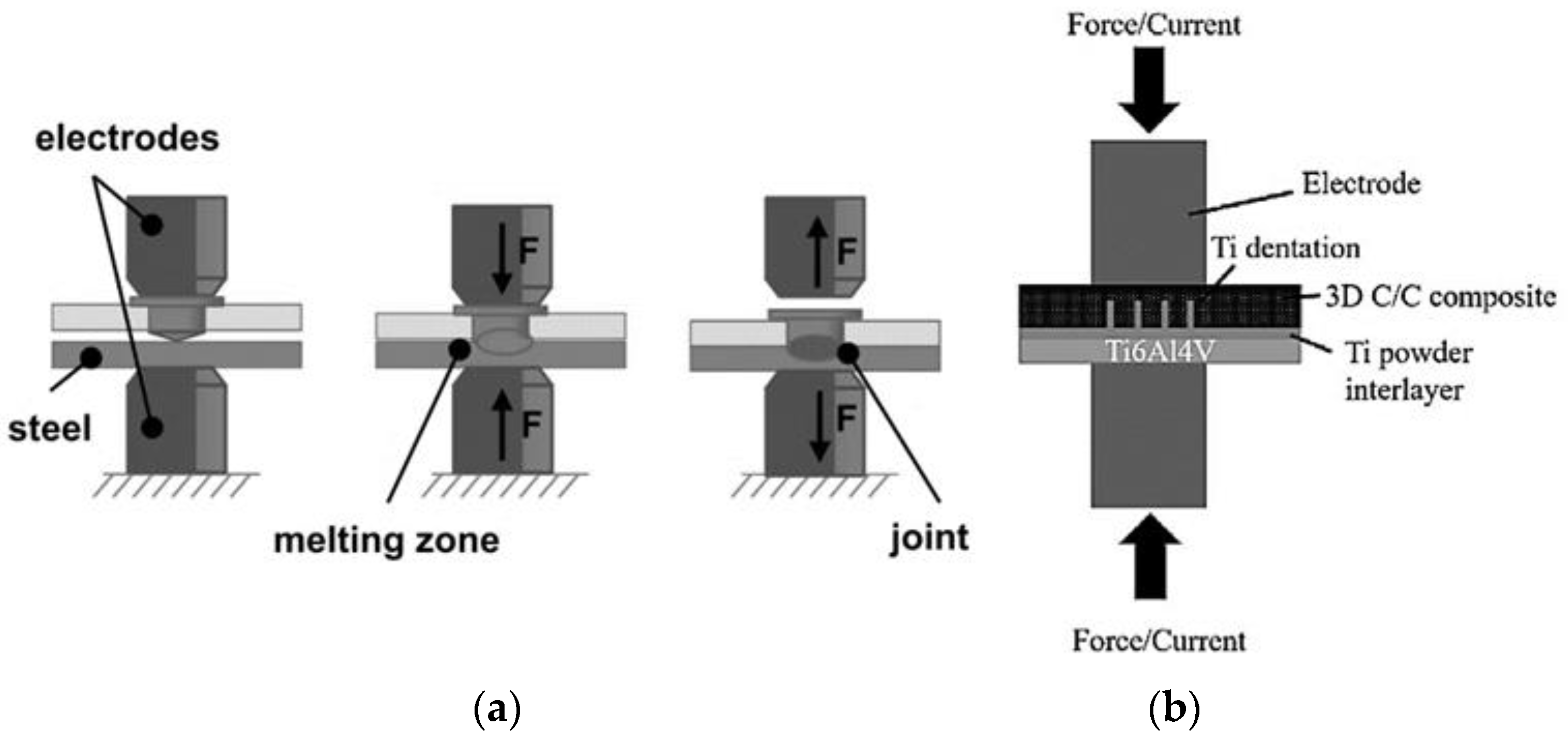
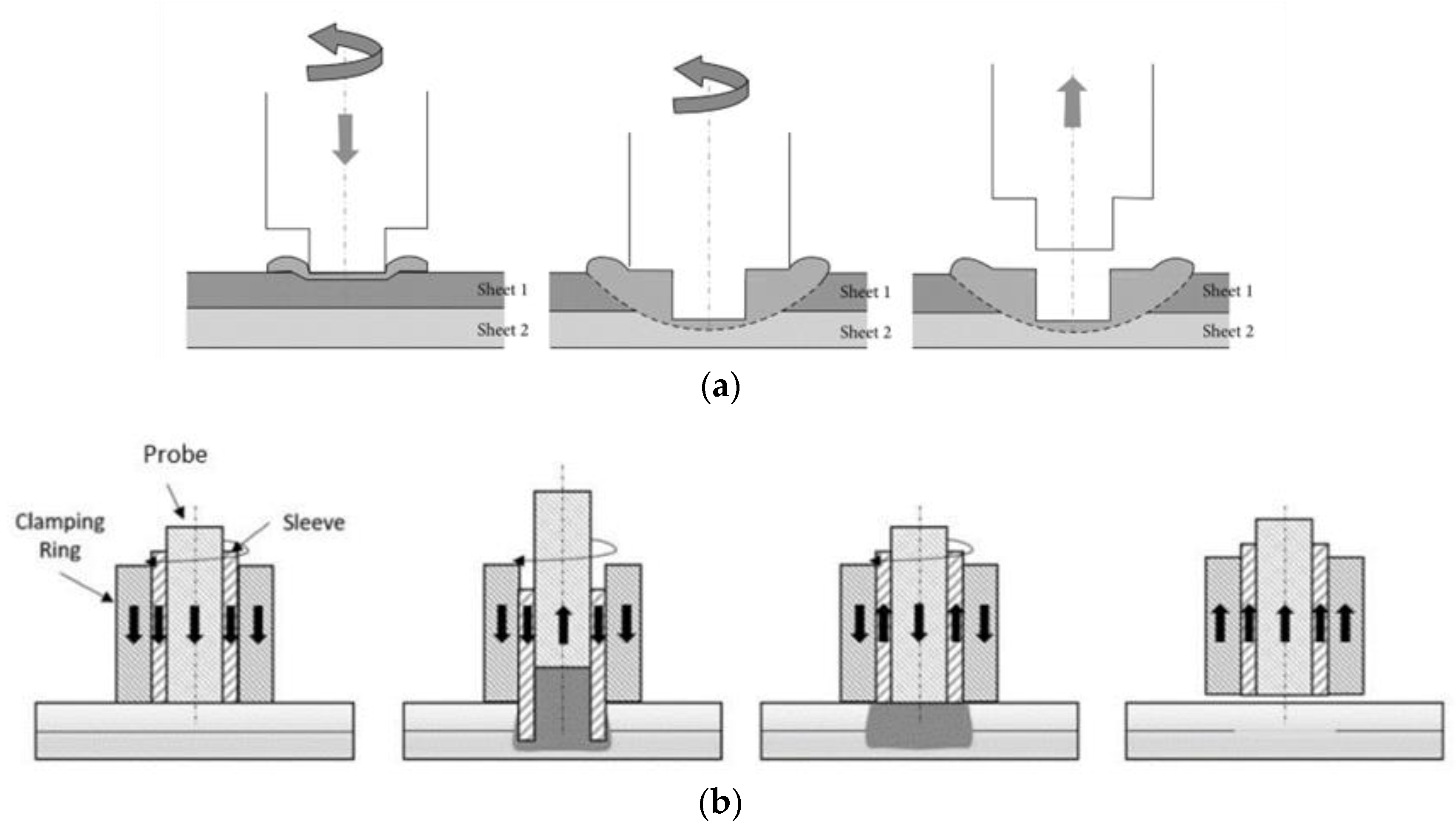
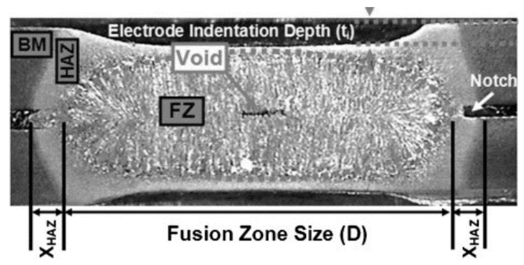
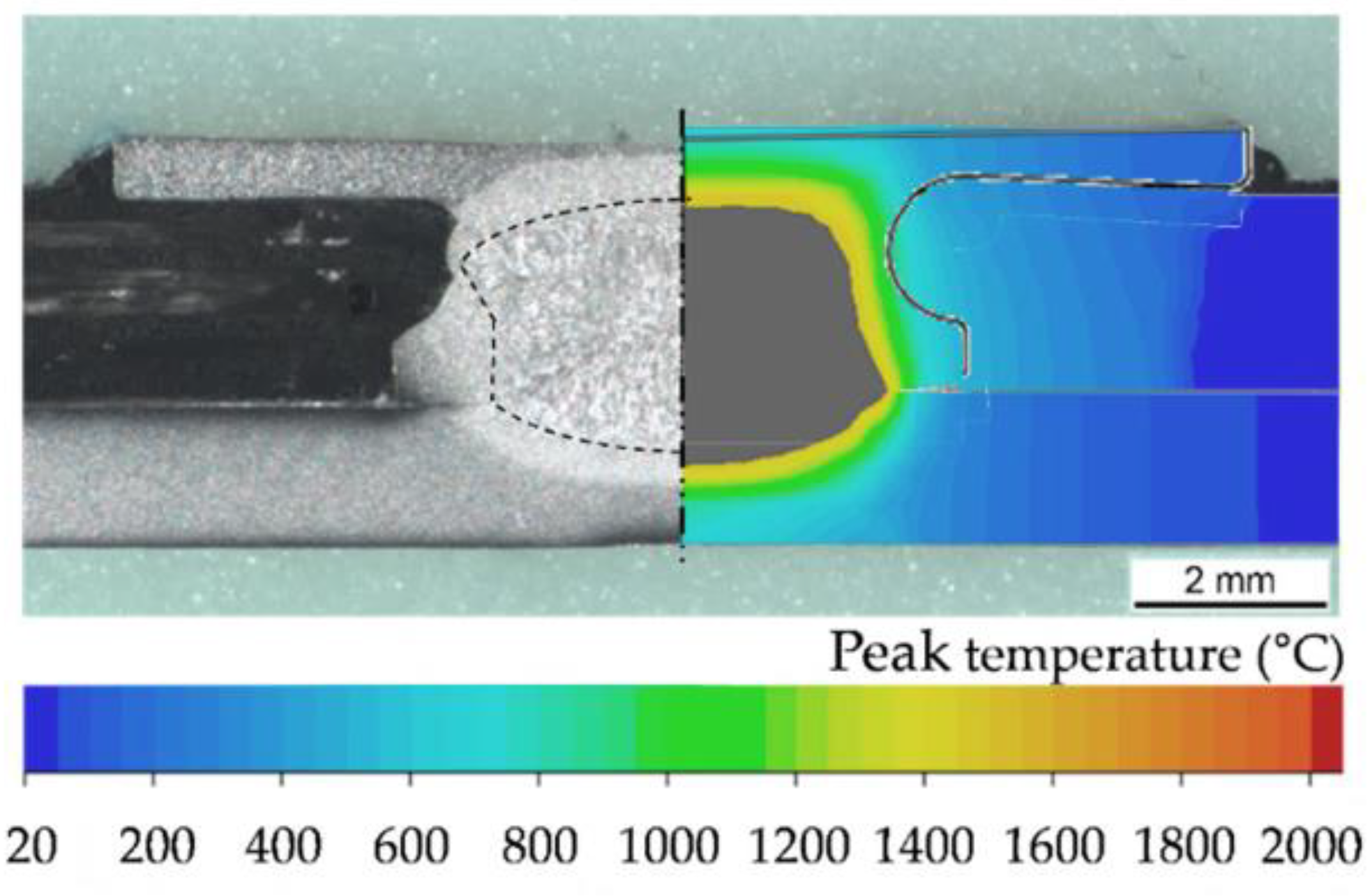
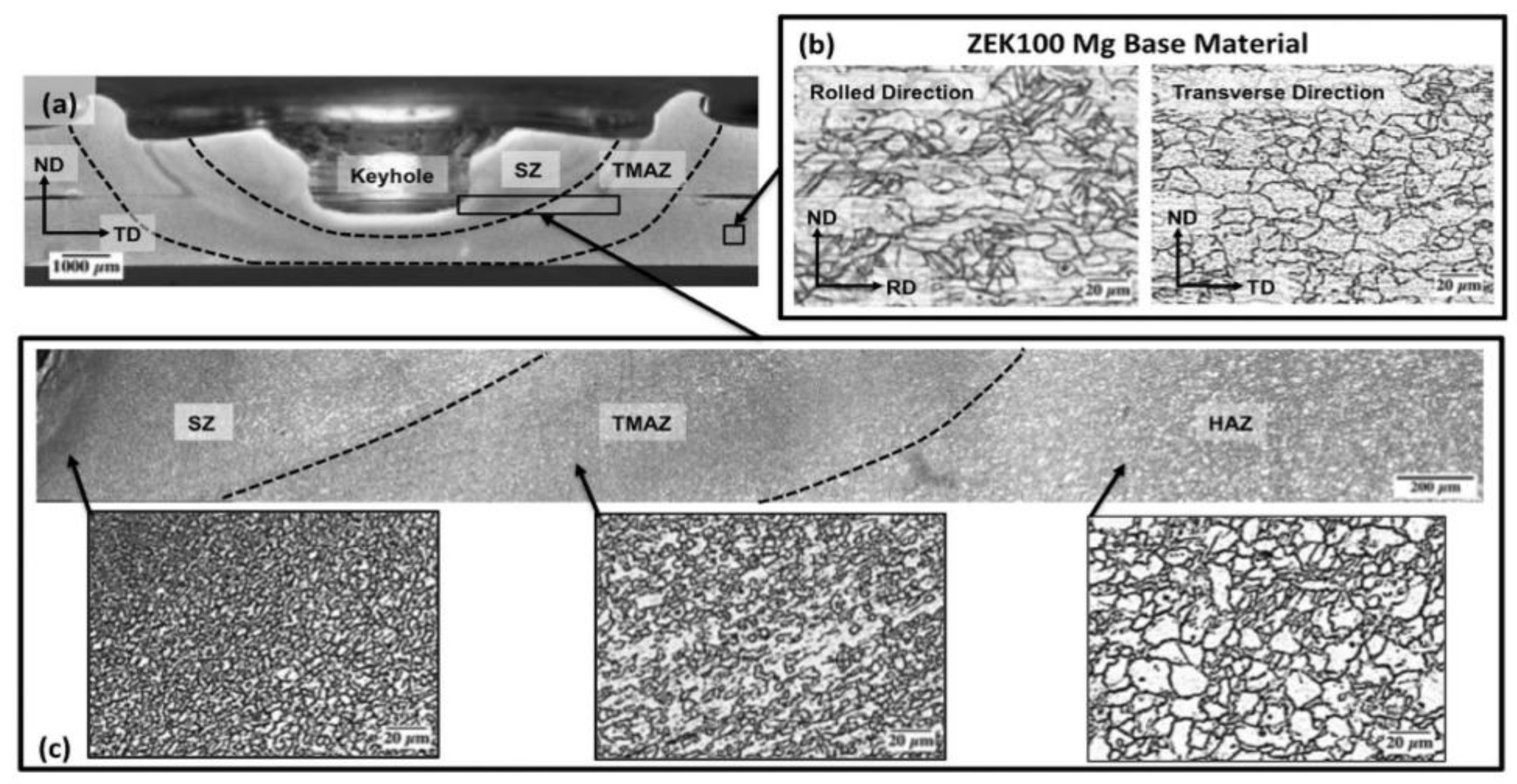
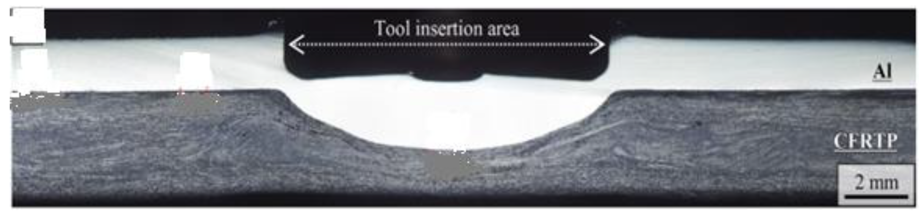
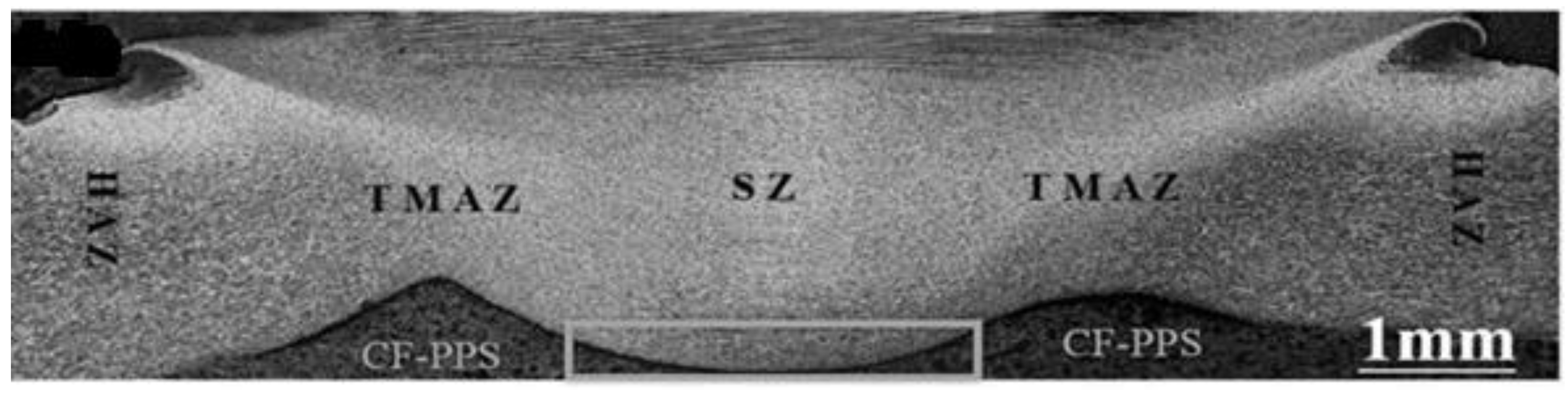
Table 1.
Use of co-axially arranged spot welding electrodes.
| Reference | Electrode Materials | Materials Joined | Results |
|---|---|---|---|
| Ren et al. [34] | CuCr for the inner electrode and SuS304 for the outer electrode | Surface-treated Al5052 (silane coupling agent) –CFRP |
|
| Szallies et al. [36] | CuCr1Zr for inner and outer electrodes | Low carbon steel (DX56)–thermoplastic (PA 6.6) and aluminum (EN AW 6016)–thermoplastics (PA 6 GF47) |
|
| Ren et al. [37] | CuCr for the inner electrode and SuS304 for the outer electrode | Surface-treated Al5052 (silane coupling agent) –CFRP |
|
Table 2.
Use of metal inserts and interlayers with RSW.
| Reference | Type of Interlayer/Metal Inserts | Materials Joined | Results |
|---|---|---|---|
| Shokati et al. [44] | Titanium (Ti) powder interlayer | Carbon–carbon C/C composite (2D and 3D) with Ti-6Al-4V alloy |
|
| Troschitz et al. [45] | Soft structural steel (S235JR) insert | Glass-fiber-reinforced polypropylene (GF/PP) and HC340LA steel |
|
| Holtschke and Jutner [43] | Boron-alloyed heat-treated steel 20MnB4 insert | LITECOR® with ultra-high-strength steel (UHSS) 22MnB LITECOR® is a steel/polymer/steel sandwich material that is referred to as SPS | The welding mechanism was the melting and solidification at the insert–steel interface, and there was no heat-related damage to the LITECOR®. |
| Calado et al. [46] | AISI304 stainless steel insert | LITECOR® with LITECOR® |
|
| Schmal and Meschut [47] | 20MnB4 coated with a ZnFe coating insert | LITECOR® with press-hardened 22MnB5 with an AlSi150 surface |
|
| Roth et al. [48,49] | D04 steel and stainless steel 304 inserts | Steel–fiber-reinforced polymer |
|
Table 3.
Use of nanoparticles and interlayers in FSSW.
| Reference | Nanoparticle/Interlayer | Materials Joined | Results |
|---|---|---|---|
| Bagheri et al. [58] Abdollahzadeh et al. [59] | Silicon carbide (SiC) nanoparticles | Al 2024–pure copper C11000 Al 5083–pure copper C11000 |
|
| Tebyani and Dehghani [60] | Silicon carbide (SiC) nanoparticles | IF steel–IF steel |
|
| Hong et al. [61] Jeon et al. [62] | Graphite nanoparticles | Aluminum 552-H32–aluminum 6061-T4 Aluminum 5052-H32–aluminum 5052-H32 |
|
| Suresh et al. [63] Enami et al. [64] Hassnifard et al. [65] | Aluminum oxide (Al2O3) nanoparticles | Aluminum 7076-T6–aluminum 7076-T6 Aluminum AA2024-T3–aluminum AA2024-T3 Aluminum 7075-T6–aluminum 7075-T6 |
|
| Sadeghi et al. [66] | Titanium oxide nanoparticles (TiO2) | IF steel-IF steel |
|
| Xue et al. [67] | Thermoplastic polyamide (PA6) interlayer | Aluminum 5182–carbon-fiber-reinforced bismaleimide (CF-BMI) |
|
| Nasir et al. [68] | Carbon-fiber-reinforced polymer (CFRP) interlayer | Aluminum alloy 7075-T651 and titanium alloy Ti-6Al-4V. |
|
| Khan et al. [69] | Polyamide PA interlayer | Aluminum alloy AA6061–PP-glass-fiber-reinforced polymer (GFRP-PP) |
|
| Kalaf et al. [70] | Carbon-fiber-reinforced polymer (CFRP) interlayer | Aluminum alloy AA5052–aluminum alloy AA5052 |
|
| Rana et al. [71] | High-density polyethylene (HDPE) interlayer | Aluminum alloy AA5052-H32–aluminum alloy AA5052-H32 |
|
Table 4.
Use of energy directors and interlayers in USW for composite joints.
| References | Energy Director (ED)/Interlayer (IL) | Materials Joined | Results |
|---|---|---|---|
| Lionetto et al. [12,90] | Polyamide 6 (PA 6) IL | Aluminum AA5754–carbon fiber (CF)/epoxy |
|
| Wang et al. [91] | Nylon-6 (PA 6) IL | Rolled cold steel (SPCC) –carbon-fiber-reinforced thermoplastic (CFRTP) |
|
| Conte et al. [92] | Polyamide 6 (PA 6) IL | Aluminum–carbon-fiber-reinforced polymer (CFRP) |
|
| Zhao et al. [93] | Polyphenylene sulfide (PPS) ED | Carbon-fiber-reinforced polyphenylene sulfide (CF/PPS)-(CF/PPS) | The bigger-diameter sonotrode increased the heating rate, reduced the weld time due to the higher heating rate, and produced a bigger weld area. This further led to a higher ultimate failure load compared to that of the sonotrode with the lowest diameter. |
| Alexenko et al. [94] | PEEK ED with carbon fiber fabric (CFF) prepreg | Polyether ether ketone PEEK-PEEK | Bonding was formed due to the complete squeezing-out of the ED and prepreg due to frictional heating, and it adhered to the PEEK material. |
| Tsiangou et al. [88] | Polyetherimide (PEI) ED + an integrated PEI IL on the CF/epoxy | Carbon fiber (CF)/PEI–CF/epoxy |
|
| Villegas et al. [95] | Polyphenylene sulfide (PPS) ED | Carbon fiber polyphenylene sulfide (CF/PPS)–CF/PPS |
|
| Palardy et al. [96] | Polyetherimide (PEI) ED | Carbon fiber/polyetherimide (CF/PEI)–CF/PEI |
|
| Tao et al. [97] | Polyetheretherketone (PEEK) ED | Carbon-fiber-reinforced polyetheretherketone (CF/PEEK)—CF/PEEK |
|
| Kiss et al. [79] | Polypropylene (PP) ED | Polypropylene (PP)-PP |
|
Table 5.
Laser welding (LW) and laser spot welding (LSW) of metal–polymer and metal–metal joints.
| Laser Welding of Metal–Polymer Composite Joints | |||
| Reference | Laser Type/Heating Method | Materials Joined | Results |
| Fernandes et al. [115] | Nd:YAG pulse/conduction laser heating | Polymethylmethacrylate (PMMA)-S235 galvanized steel |
|
| Schricker et al. [116] | Diode laser/conduction laser heating | Polyamide (PA 6, PA6.6) and polypropylene–high alloyed steel AISI304 and aluminum alloy AA6082 |
|
| Lambiase and Genna [117] | Diode laser/transmission laser heating | Polycarbonate (PC)–stainless steel AISI304 |
|
| Lambiase and Genna [118] | Diode laser/conduction laser heating | AA5053 aluminum alloy–polyetheretherketone (PEEK) |
|
| Ma et al. [119] | Diode laser/conduction laser heating | Carbon-fiber-reinforced polymer (CFRP)–aluminum with polycarbonate (PC) interlayer |
|
| Huang et al. [120] | Nd:YAG pulse/conduction laser heating | Polymethylmethacrylate (PMMA)–stainless steel AISI304 |
|
| Hussein et al. [121] | Nd: AG pulse/conduction laser heating and transmission laser heating | Polymethylmethacrylate (PMMA)–stainless steel 304 |
|
| Meiabadi et al. [114] | Nd:YAG pulse/conduction laser heating | AISI1008 low-carbon steel–polycarbonate (PC) |
|
| Lin et al. [122] | Fiber laser/conduction laser heating | Steel (DP590)–thermoset carbon-fiber-reinforced material with polycarbonate (PC) interlayer |
|
| Laser Spot Welding of Metal–Metal Dissimilar/Similar Joints | |||
| Reference | Laser Type/Heating Method | Materials Joined | Results |
| Pardal et al. [123] | Fiber laser/conduction laser heating | Aluminum alloy 5083–mild steel, Grade CR4 |
|
| Chen et al. [124] | Disc laser/conduction laser heating | Press-hardened steel (22MnB5)–press-hardened steel (22MnB5) with an Al-Si coating |
|
| Shengjie et al. [125] | Fiber laser/conduction laser heating | Dual-phase (DP)steel DP590–aluminum alloy AA7075 |
|
| Kumar et al. [126] | Fiber laser/conduction laser heating | Inconel 718–steel 410 |
|
Table 6.
Comparison between RSW, FFSW, LSW, and USW in terms of joining state, tool used for welding, source of heating, and materials commonly joined.
Table 6.
Comparison between RSW, FFSW, LSW, and USW in terms of joining state, tool used for welding, source of heating, and materials commonly joined.
| Process | Joint State | Welding Tool | Source of Heating | Material |
|---|---|---|---|---|
| RSW | Fusion | Electrode | Resistance | Mainly ferrous and nonferrous metals |
| FSSW | Solid-state | Pin/pinless rotating tool | Friction | Metal + polymer composites |
| USW | Solid-state | Sonotrode | Friction | Metal + polymer composites |
| LSW | Fusion | - | Laser beam | Metal + polymer composites |
Disclaimer/Publisher’s Note: The statements, opinions and data contained in all publications are solely those of the individual author(s) and contributor(s) and not of MDPI and/or the editor(s). MDPI and/or the editor(s) disclaim responsibility for any injury to people or property resulting from any ideas, methods, instructions or products referred to in the content. |
© 2024 by the authors. Licensee MDPI, Basel, Switzerland. This article is an open access article distributed under the terms and conditions of the Creative Commons Attribution (CC BY) license (https://creativecommons.org/licenses/by/4.0/).
Share and Cite
MDPI and ACS Style
Arumugam, A.; Pramanik, A. A Review on the Recent Trends in Forming Composite Joints Using Spot Welding Variants. J. Compos. Sci. 2024, 8, 155. https://doi.org/10.3390/jcs8040155
AMA Style
Arumugam A, Pramanik A. A Review on the Recent Trends in Forming Composite Joints Using Spot Welding Variants. Journal of Composites Science. 2024; 8(4):155. https://doi.org/10.3390/jcs8040155
Chicago/Turabian StyleArumugam, Aravinthan, and Alokesh Pramanik. 2024. "A Review on the Recent Trends in Forming Composite Joints Using Spot Welding Variants" Journal of Composites Science 8, no. 4: 155. https://doi.org/10.3390/jcs8040155