Article

Effect of Chitin Nanocrystal Deacetylation on a Nature-Mimicking Interface in Carbon Fiber Composites

by
Abdellatif M. Abdel-Mohsen
1,
Rasha M. Abdel-Rahman
1,
Lukáš Kalina
2,
Vishakha Vishakha
3,
Ludmila Kaprálková
1,
Pavel Němeček
1,
Josef Jančář
2,3 and
Ivan Kelnar
1,*
1
Institute of Macromolecular Chemistry, Czech Academy of Sciences, Heyrovského nám. 2, 162 00 Praha, Czech Republic
2
Materials Research Center, Faculty of Chemistry, Brno University of Technology, Purkyňova 464/118, 612 00 Brno, Czech Republic
3
CEITEC-Central European Institute of Technology, Brno University of Technology, Purkyňova 656/123, 612 00 Brno, Czech Republic
*
Author to whom correspondence should be addressed.
J. Compos. Sci. 2024, 8(5), 163; https://doi.org/10.3390/jcs8050163
Submission received: 31 January 2024 / Revised: 15 April 2024 / Accepted: 23 April 2024 / Published: 26 April 2024
(This article belongs to the Special Issue Carbon Fiber Composites, Volume III)

Abstract

:
The formation of a rigid, tough interface based on a nacre-like structure in carbon fiber (CF) composites is a promising way to eliminate low delamination resistance. An effective method of coating CFs is electrophoretic deposition (EPD), which, in the case of dissimilar components like graphene oxide (GO) and polymeric glue, usually requires chemical bonding/strong interactions. In this work, we focus on chitin nanocrystals (ChNCs), leading to an excellent mechanical performance of artificial nacre, where favorable interactions and bonding with GO are controlled by degrees of deacetylation (5, 15, and 30%). We prepared coatings based on GO/ChNC adducts with 95/5, 90/10, 50/50, and 25/75 ratios using optimized EPD conditions (pH, concentration, voltage, and time). The prepared materials were characterized using FTIR, TEM, XPS, SEM, DLS, and XRD. SEM evaluation indicates the formation of a homogeneous interlayer, which has a fair potential for chemical bonding with the epoxy matrix. Short-beam testing of epoxy matrix composites indicates that the coating does not decrease stiffness and has a relatively low dependence on composition. Therefore, all coatings are promising for a detailed study of delamination resistance using laminate samples. Moreover, facile EPD from the water solution/suspension has a fair potential for industrial applications.

1. Introduction

It is now well accepted that combinations of carbon nanoplatelets (CN) with small amounts of various polymers [1,2,3] and polysaccharides [4] may form nature-mimicking materials with unique compact structures and impressive mechanical parameters, which can exceed those of nacre, that is, the natural ‘gold standard’ of strong, tough material [5,6].
It was recently demonstrated that analogous materials with unique performance (deformation mechanism) can be obtained by combining CN with suitable organic anisotropic nanoparticles, mostly nanofibrils/whiskers. An example is a system containing reduced graphene oxide (GO) and covalently linked cellulose nanofibrils (CNC) [7] with a typical composition for nacres (80–97% GO), some other nanoplatelet/CNC combinations [7,8,9,10,11,12] or the nanofibrillated cellulose/CN/diblock protein system [13]. Other high-performance nature-mimicking materials are based on different silk fibroin/GO combinations [14,15].
So far, only one study has reported the application of chitin nanocrystals (ChNCs) in a system combining silk nanofibril, hydroxyapatite nanocrystals, and ChNCs [16]. These results are consistent with the fact that nacre is a ternary composite consisting of aragonite platelets, nanofibrillar chitin, and protein [5]. In this respect, considering the prime importance of interactions/linking between components [7,10], we can consider the promising potential of nanosized polar amino-functionalized ChNCs with a favorable aspect ratio (AR) to form GO-based nacre analogs. Furthermore, ChNC preparation is easier than nanofibrillated cellulose, with further benefits in using waste material [17,18].
ChNCs, mostly prepared from chitin, is a rigid crystalline nanofiber with Young’s modulus at 40–80 GPa. It comprises repeating units of glucosamine and N-acetylglucosamine that contain reactive groups, i.e., amines. Thus, chitin has more significant potential for chemical modifications than cellulose. Chitin nanocrystals can be produced in a relatively wide range of lengths, diameters, charge densities, types of charge, and crystallinity through various top-down procedures [17,18,19,20].
In the area of fibrous composites, different nanoparticles, mainly CN and CNT, are applied to modify the interface as a single coating. This includes electrophoretic deposition (EPD) [21,22] and carbon vapor deposition [23], components of sizing [24], or even direct linking to CF to form hierarchical hairy fibers [25,26,27].
In the case of cellulose nanocrystals (CNC) and microfibrils [28,29,30] or silane-modified CNC [30], various dip coatings of glass fibers and carbon fibers (CFs) are reported, while aramid fibers were coated with aramid microfibers by EPD [30,31] or by the dip coating of the aramid microfibers/graphene combination [32]. This modification of the fiber surface provides the benefit of enhanced roughness, increasing frictional adhesion components, and higher interphase modulus. At the same time, an important deficiency of composites with low resistance against impact-delamination [33] (interlaminar cracking) can be eliminated by a tough, usually low-modulus interface [34] due to an increase in impact energy release. However, this leads to a significant reduction in stiffness [35].
Fair mechanical properties, including increased interlaminar shear strength (ILSS), were found with a more rigid coating by CNC [28,29]. At the same time, the solution by various methods that improve the toughness of the matrix brings processing limitations and a reduction in resistance against fiber buckling [36]. On the basis of the above facts, we consider the important role of the tough, rigid interfaces using nature-mimicking nacre-like structures. So far, rigid-soft structures based on carbon nanotubes (CNTs) modified with the poly(ethylene glycol)methylether [37] and CNT/polyetherimide combination [37] have been reported. However, unlike the comparable effect on a single coating using neat GO or CNT [38] to enhance interfacial properties, the ability of tubular nanoelements to form effective complex structures with polymers and excellent mechanical properties is limited. In the case of 2D platelets, the potential to create effective ordered nacre-mimicking “brick and mortar” structures and, thus, a rigid, tough interface is more marked [5,38].
So far, only some layer-by-layer deposition of alternating polymer/nanoparticle (NP) layers has been reported. Examples are layers of polydopamine (PDA)/GO [39,40], PDA/polyhedral silsesquioxane (POSS) [41], or PDA/NiOH platelets [42]. The grafting of nanoparticles to the deposited polymeric layer [43] has also been reported.
Recently, we prepared CF coatings using nacre-like interlayers by EPD of PDA-coated GO or some polymer-grafted GO combinations, showing an excellent ability to enhance ILSS without loss of stiffness [37]. To control the composition of EPD coatings in the two-component system, the grafting of an aminated polymer to GO or borate-mediated interactions/bonding of hydroxyl-containing poly(vinylalcohol) and carboxymethylcellulose was necessary. Therefore, this study is aimed at highlighting the potential of alternative nacre-like coatings of carbon fibers based on GO with attached chitin nanocrystals (GO/ChNC adducts) to upgrade epoxy/fiber composites together with a thorough study of the effect of ChNCs parameters and adduct composition on the electrophoretic deposition of the multiscale rigid tough hierarchical interphase.

2. Experimental Part

2.1. Materials

Epoxy resin LG700 based on diglycidyl ether of bisphenol A (DGEBA) + hardener HG737 (GRM Systems, s.r.o.). Chitin flakes, 1-ethyl-3-(3-dimethylaminopropyl) carbodiimide hydrochloride (EDC), and N-hydroxysuccinimide (NHS) were purchased from Sigma Aldrich (Praha, Czech Republic); graphite flakes were from (Graphite Týn, Týn nad, Vltavou, Czech Republic); and the carbon fiber (CF) roving yarn filament Torayca T700SC 12 k was from GRM Systems, s.r.o. (Olomouc, Czech Republic).

2.2. Preparation of Graphene Oxide (GO)

The modified Hummer’s method [44] was used; briefly, 95 mL of concentrated sulfuric acid and 2 g of NaNO3 were added to 4 g of graphite flakes in an ice bath. In total, 12 g of KMnO4 was slowly added, and the mixture was stored at 35 °C for 100 min. Then, 184 mL of water was added while the temperature increased to ~95 °C. After 15 min, 420 mL of water with 5 mL of 30% H2O2 was added. The residue was washed with a mixture of water, 35% HCl, and ethanol by centrifugation. The oxygen content was ~40%, as evaluated using elemental analysis. The final ~2% water suspension was delaminated using a Bandelin 200 W sonicator with 30% amplitude for 15 min.

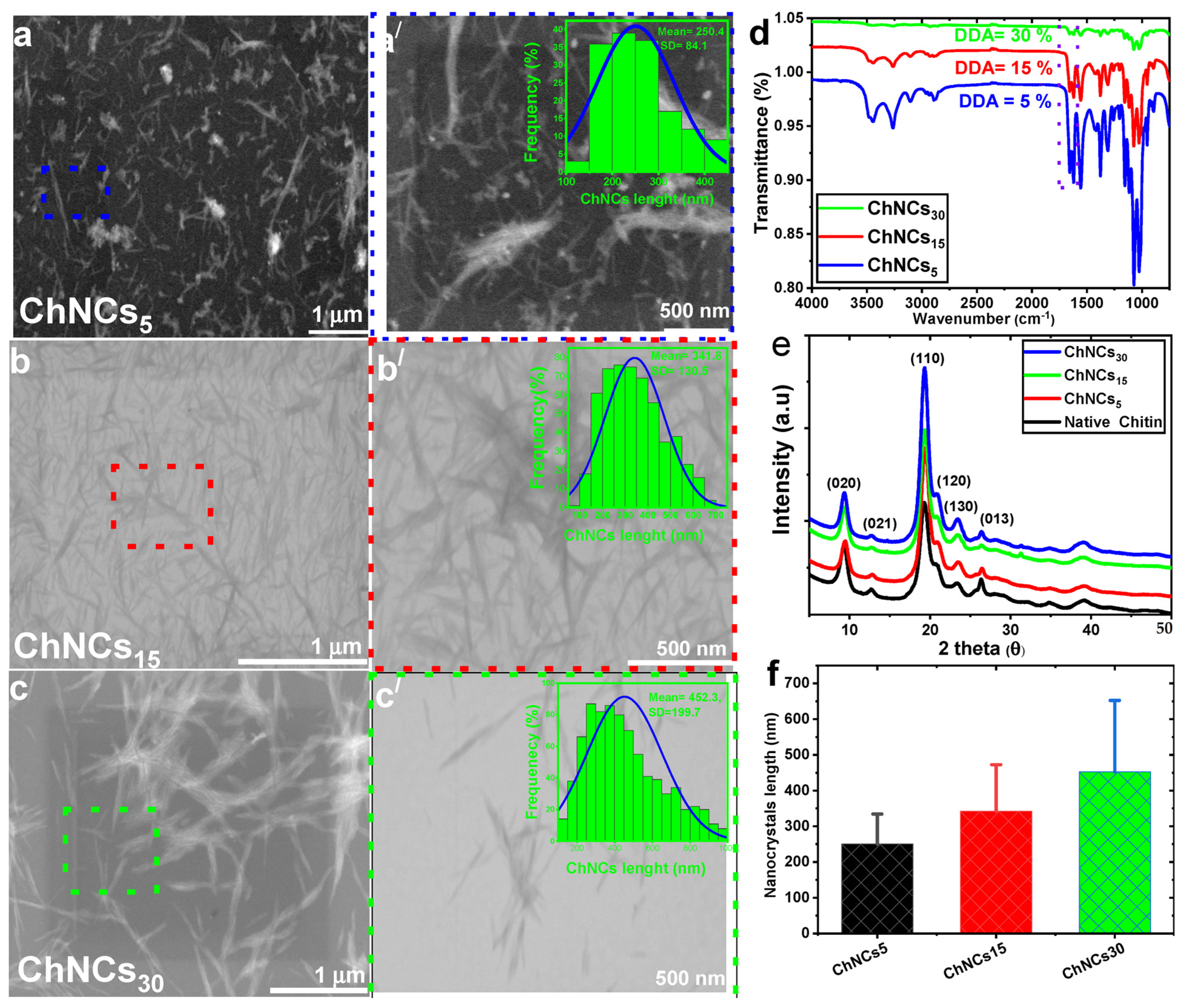
2.3. Preparation of Chitin Nanocrystals (ChNCs)

Chitin nanocrystals (ChNC) with different degrees of deacetylation (DDA) were prepared according to our previous works [18,45]. Briefly, chitin nanocrystals were synthesized by an acid hydrolysis process using HCl (5 M) for 6 h at 90 °C, and the solid-to-medium-solution ratio was approximately (1/100). The nanocrystals were obtained after centrifugation at 7500 rpm for 30 min at room temperature. ChNCs were dialyzed using a cellulose membrane cut (12–14 KDa) for one week at room temperature using deionized water, which changed every 12 h until the pH reached 4.5. ChNCs were stored at 4 °C in a refrigerator until further use. The DDA of ChNCs was 5, 15, and 30% DDA from 13C-CP/MAS NMR [18], respectively. The degree of deacetylation was also confirmed by FTIR spectroscopy in combination with XRD [45]; see Figure S1a,b.

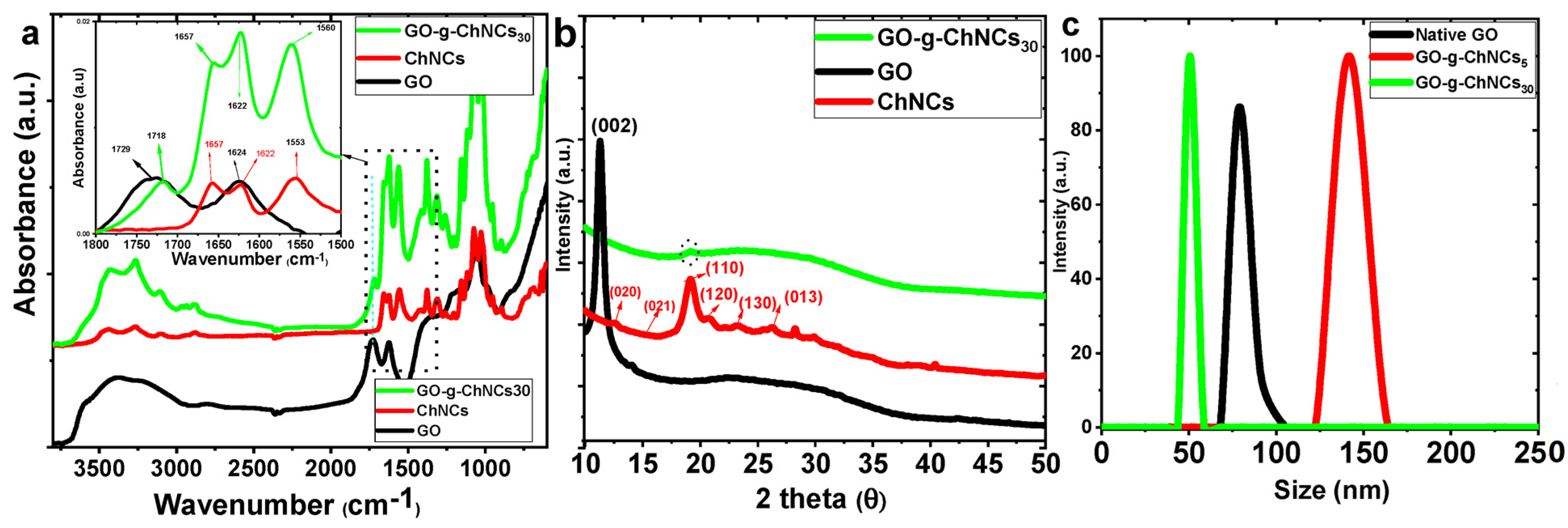
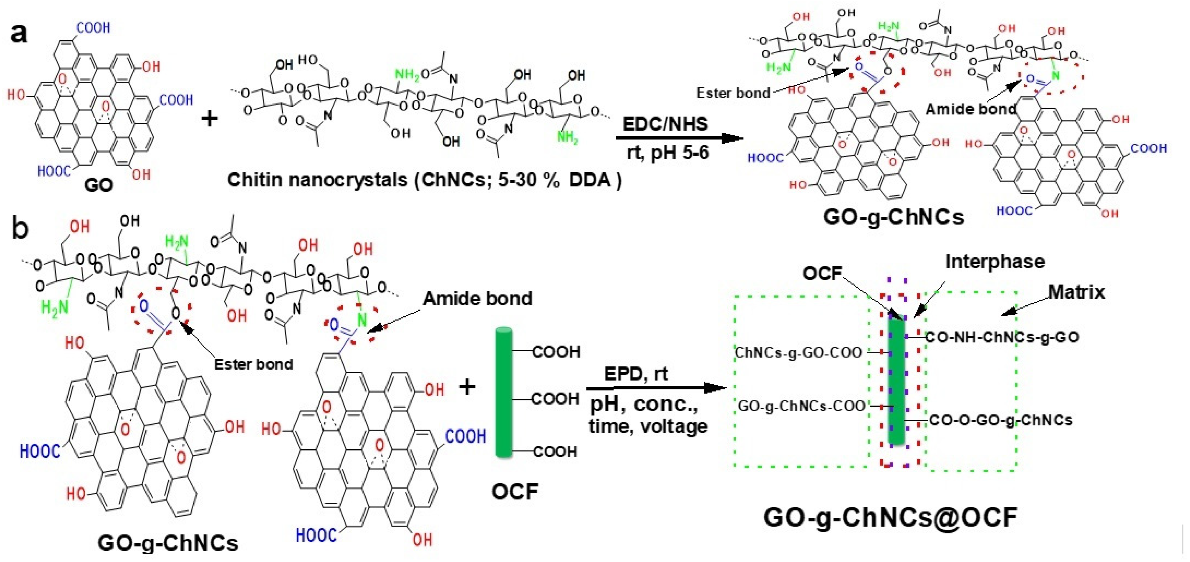
2.4. GO/ChNC Adduct Synthesis

A certain amount (0.5%) of GO was dispersed in deionized water. Then, 50/25 mM of EDC/NHS was added to the GO while stirring for 2 h at room temperature to activate the carboxylic and epoxide groups of the GO. ChNCs with different degrees of deacetylation (5, 15, 30% DDA) were added to the GO suspension drop by drop with stirring for 5 h at room temperature to obtain the GO/ChNC adduct. The prepared materials were coded according to DDA (GO/ChNCs5, GO/ChNCs15, and GO/ChNCs30 adducts). The materials obtained were dialyzed for 3 days at rt using deionized water.

2.5. Electrophoretic Coating

Oxidized carbon fibers (OCFs), prepared with nitric acid at 22 °C for 120 h according to our previous work [46], were fixed between two stainless steel electrodes with a distance of ~10 mm. Electrophoretic deposition (EPD) proceeded according to the details in Table 1, also showing the composition of the respective adducts. The applied voltage was 5, 10, and 20 V, respectively, and three concentrations of GO/ChNC adducts (5, 10, and 15 mg/mL) were applied. Moreover, coating was performed at various pHs (3.5, 7.5, and 11) and times of 10 and 20 min. After washing and drying, the composite bar was prepared (see Section 2.5). According to the literature, surface oxidation of CF has a negligible effect on the mechanical parameters of CF [47].

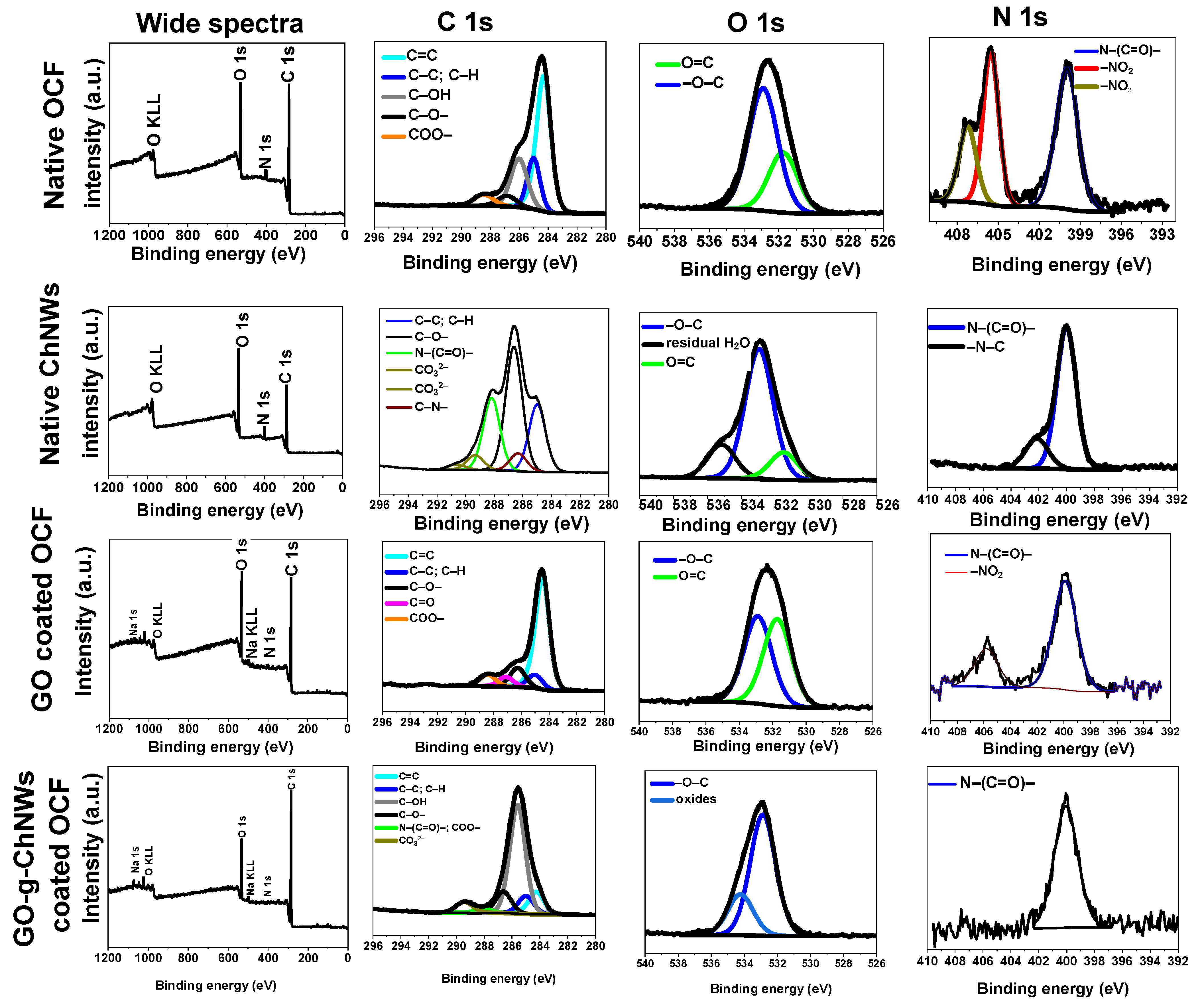
2.6. Characterization of OCF Coated with a GO/CHNC Adduct

Attenuated total reflectance Fourier transform infrared spectroscopy (ATR-FTIR) was carried out using a Bruker Vertex V70 FTIR spectrometer and a Bruker Platinum ATR accessory (Bruker GmbH, Ettlingen, Germany) with a single reflection diamond crystal mount (Bruker Optik GmbH, Ettlingen, Germany). Samples were clamped directly against the diamond crystal using the platinum ATR sample clamp mechanism, ensuring consistent pressure per sample. Spectra were collected in the wavenumber region 3900–650 cm−1. Four data sets per sample were recorded, adding 128 interferograms per set. Spectra were measured at a resolution of 4.0 cm−1, and 128 background scans per sample were collected. The averaged spectra per sample were generated using the Bruker OPUS version 7.2 software, where all spectra were corrected for ATR.
Short-beam strength (SBS), also called interlaminar shear strength (ILSS), if applied to laminate samples, was determined according to ASTM D2344/D2344M using beam samples 3 × 6 × 18 mm. These samples were cut from unidirectional composites prepared by the manual impregnation/mixing of a bundle of a weighed amount of CF (0.52 g) with epoxy in a silicone mold. The dimension of mold was 3 × 6 × 60 mm; the length of CF was ~60 mm. The three-point short-beam bending test (span length 12 mm, span length to thickness ratio of 4) was performed with Instron 5800 apparatus using 1 mm/min crosshead speed. The morphology of native GO, ChNC, and GO/ChNC adduct with different DDA (%) was visualized by transmission electron microscopy (TEM). The experiment was carried out with a Tecnai G2 spirit 12 electron microscope (FEI, Brno, Czech Republic). The surface of the fibers and fracture surfaces was observed using a scanning electron microscope (SEM) using a, Maia apparatus(FEI, Brno, Czech Republic) at 3 kV.
The rheological characterization of water suspensions (5 mg/mL) of native GO, ChNCs, and the GO/ChNC adduct was conducted at room temperature using the ARES G2 Rheometer (TA Instruments, New Castle, IN, USA). Parallel plates with cone/plate geometry (cone angle of 2°, diameter of 40 mm) were used. Frequency sweep measurements were made in the range from 0.05 to 100 rad/s at a 1% strain amplitude.
The X-ray photoelectron spectroscopy (XPS) of oxidized CF (OCF), neat ChNW, GO, and coated OCF was carried out with the Kratos Analytical Axis Ultra DLD system (Kratos Analytical, Manchester UK) using a monochromatic Al Kα (hν = 1486.7 eV) operating at 75 W (5 mA, 15 kV). Spectra were obtained using an analysis area of ~300 × 700 µm. The Kratos charge neutralizer system was used for all analyses. The high-resolution spectra were measured with 0.1 eV step size and 20 eV pass energy. The instrument base pressure was 2·10–8 Pa. Spectra were analyzed using the CasaXPS software (version 2.3.15) by applying a Gaussian–Lawrence line shape for fitting and the ORIGIN 2016 software.
X-ray diffraction patterns were collected using a D-8 Advance diffractometer (Bruker AXS, Karlsruhe Germany) with a Bragg–Brentano (θ-θ) goniometer (radius 217.5 mm) equipped with a secondary beam curved graphite monochromator and Na (Tl) I scintillation detector. The generator was operated at 40 kV and 30 mA.

3. Results and Discussions

3.1. Effect of DDA on GO/ChNC Adduct Formation

The degree of deacetylation (%) affected the morphology of the ChNCs, as is clear from (Figure 1a–c), showing the STEM of the ChNCs with different DDAs. At a lower DDA %, ChNCs show high aggregation with short crystal length (Figure 1a,f); when increasing the DDA from 15 to 30%, the nanocrystals are slightly longer compared to 5 DDA (Figure 1b,c,f). Figure 1d shows the FTIR of ChNCs with different DDAs. The peak intensity ratio between the amino-to-acetamide groups increased with an increase in the amino group content from 5 to 30 DDA. Figure 1e shows the XRD of native chitin and ChNC within different DDAs (5, 15, 30%). From XRD, all the pristine chitin and ChNCs with different DDAs exhibited six diffraction peaks at 2θ = 9.5°, 12.8°, 19.2°, 20.71°, 23.4° and 26.4°, indexed as (020), (021), (110), (120), (130) and (013), respectively (Figure 1e), suggesting the crystalline structure of the α-chitin [18,48,49]. From Figure 1e, DDA did not significantly affect the crystallization of the ChNCs.
Our preliminary results indicate that different charge densities and mobility/dimensions of both GO and ChNCs practically exclude the control of electrophoretic deposition (EPD) of these two-component systems, similar to other GO/polymer combinations [46]. Therefore, mutual bonding between components, using their functionality enabled by EDC/NHS, was applied to prepare the GO/ChNC adduct. When optimizing the EDC/GO/ChNCs/NHS ratio, amide and ester bonds between GO and ChNCs were created (Scheme 1a).
From Figure 2, it follows that the formation of a GO/ChNC polyelectrolyte complex and crosslinking reduced absorption for the OH and NH/NH2 stretching vibration peaks. Furthermore, a new peak in the 1718 cm–1 region showed the esterification reaction between the –COOH of graphene oxide (GO) and –OH of ChNCs. The band in the spectrum of native GO at 1729 cm–1 was naturally broad due to the presence of various types of “carbonyls” and was sharper after the ester bond formed after grafting with ChNCs30 (Figure 2a). The strong ionic interaction between carboxylic/epoxide GO and amino/hydroxyl ChNCs in the presence of an EDC/NHS crosslinker agent (Figure 2a) caused the peak intensity of the free amino groups at 1553 cm−1 to weaken.
Figure 2b shows the XRD patterns of the GO, ChNCs30, and GO/ChNC adduct30. The diffraction peak of GO appeared at 2θ = 11.5°, which was associated with the characteristic peak (001 plane) of the interlayer structure of the GO nanosheets [50,51,52]. The ChNCs30 diffraction peaks exhibited six diffraction peaks at 2θ = 9.5°, 12.8°, 19.2°, 20.71°, 23.4° and 26.4°, indexed as (020), (021), (110), (120), (130) and (013), respectively. GO grafted with ChNCs30 showed only broader diffraction peaks at 2θ = 20–30°, attributed to the presence of GO and ChNCs. Chitin nanocrystals are considered to be intercalated in the layered GO nanosheets.
Figure 2c shows the DLS of the native GO, GO/ChNCs5 adduct, and GO/ChNCs30 adduct. The size distribution of the native GO was about 90 nm, whereas, for the GO/ChNCs5 adduct, it decreased to 55 nm. At higher DDAs, the size distribution of the adduct was about 150 nm. This corresponds to the size of the ChNCs increasing with increased DDA from 5 to 30% (Figure 1).
Interestingly, the rheological characterization of water suspensions (Figure S2a) indicates substantially improved viscosity for adducts compared to both constituents, with the highest value for adducts containing 75% ChNC. This indicates the important effect of the adduct composition on its size, shape, and interactions.
Figure 3 shows fine ChNCs (Figure 3a,b) and a very thin layer of GO with a smooth surface (Figure 3c,d). The GO/ChNC adduct showed a layered structure with a larger thickness against GO, indicating adduct formation (Figure 3e,f).
From the XPS analysis of the adduct composition (Figure 4), it follows that only C, O, and N were detected from the broad spectra of oxidized carbon fibers (OCF). OCF C 1 showed different binding energies of –C=C, –C–C, –C–OH, –C–O, –COO, at 284.26 284.96, 286.03, 286.9 and 288.2. Ev. From the C 1s and O 1s data, we can confirm that due to the nitric acid used to oxidize the carbon fiber, a partial nitration reaction was observed in N 1 (Figure 4). The broad XPS spectrum of native ChNCs showed expected signals for C, O, and N. The C 1s of native ChNCs showed that the binding energy of 289.33 and 290.62 belongs to the carbonate region. The C 1s spectrum showed the bonds of carbon with nitrogen. The binding energies of 289.33 and 290.62 belong to the region of carbonyl groups coordinated with water molecules. The binding energy at 288.18 relates to amide bonds, and 286.32 is connected to C–N bonds (primary amino groups). The O 1s of native ChNCs were observed only at 532.9 and 531.5 eV in relation to the –C–O and –C=O groups in the chemical structure. Partially deacetylated ChNCs show two binding energies at 400.01 and 402.14 that correspond to amide (N–C=O) and positively charged nitrogen (Figure 4).
From the wide spectrum of native graphene oxide, as shown in the figure above, only O and C are observed. C 1s of GO@OCF show carbon in the hybridization state sp3 (285 eV) and sp2 (284.5 eV). The peak of carbon in the sp2 state indicates a strong asymmetry, as expected, with a high proportion of C–O bonds. The different binding energies at 284.5, 286.67, 288.24, and 285 eV correspond to C=C, C–O, COOH, and C–C/C–H, respectively.
Oxidized carbon fibers coated with native graphene oxide (GO@OCF) are shown in Figure 4. As expected from the wide-spectrum data, C, O, and Na peaks were observed. The presence of a sodium hydroxide peak was due to the neutralization of OCF with NaOH after the oxidation step, which resulted in a salt form (–COONa). The C 1s spectrum shows carbon in two hybridization states as in the native GO spectrum. However, the contribution of C–O bonds decreases in comparison to that of pure GO. The spectrum contains the bonds C=O and ester groups. A new ester group appeared in the C 1s spectrum of GO@OCF at 288.42 eV, belonging to carbon in the ester groups, due to the esterification reaction between GO and OCF. The intensity of C-O groups of GO@OCF was decreased compared to native GO due to the interaction between OCF and GO.
From the wide spectrum of GO/ChNC adduct@OCF, only C, O, and N peaks appeared, and these peaks were peaks for Na as well. C 1s of GO/ChNC adduct@OCF show different binding energies at 284.24, 285, 285.6, 286.62, 288.07, 289.41 corresponding to C=C, C–C/CH, C–OH, C–O–, N–C=O–/COO– and carbon binding with water molecules. From the C 1s spectrum, we could conclude that an esterification/amidation reaction could occur between the functional group of the GO/ChNC adduct and groups of OCF. From the N 1s spectrum of the GO/ChNC adduct@OCF, only the N–C=O peak appeared, and no C–N peak appeared for free amino groups of partially deacetylated ChNCs. From both C 1 and O 1 of GO/ChNC adduct@OCF, both esterification and amidation reactions could occur between the GO/ChNC adduct and OCF (Figure 4). Unfortunately, the high complexity of the whole system [46] did not allow for the precise calculation of the GO/ChNC ratio. To conclude, both XPS and FTIR indicated interactions/bonding between components in the GO/ChNC adduct.

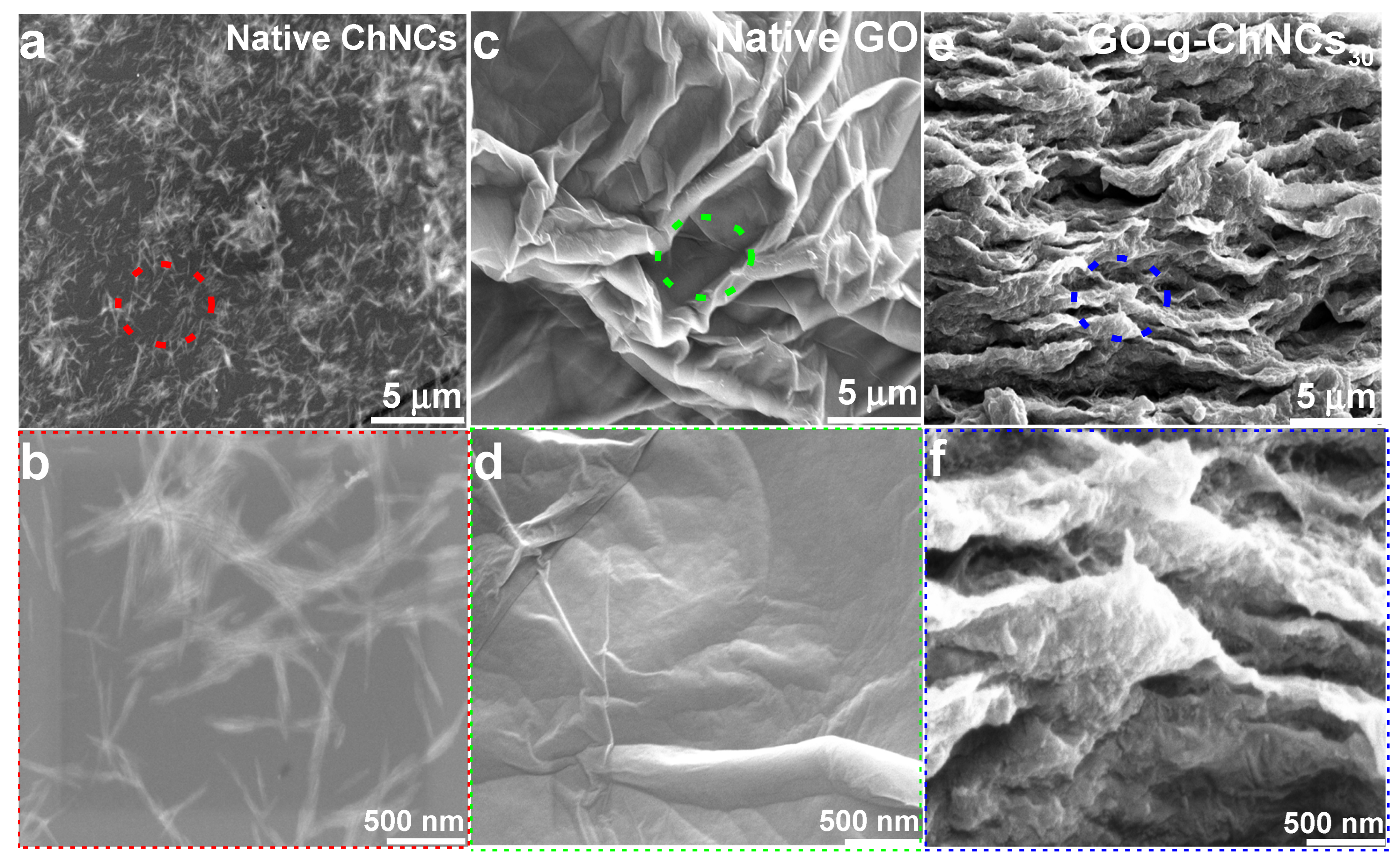
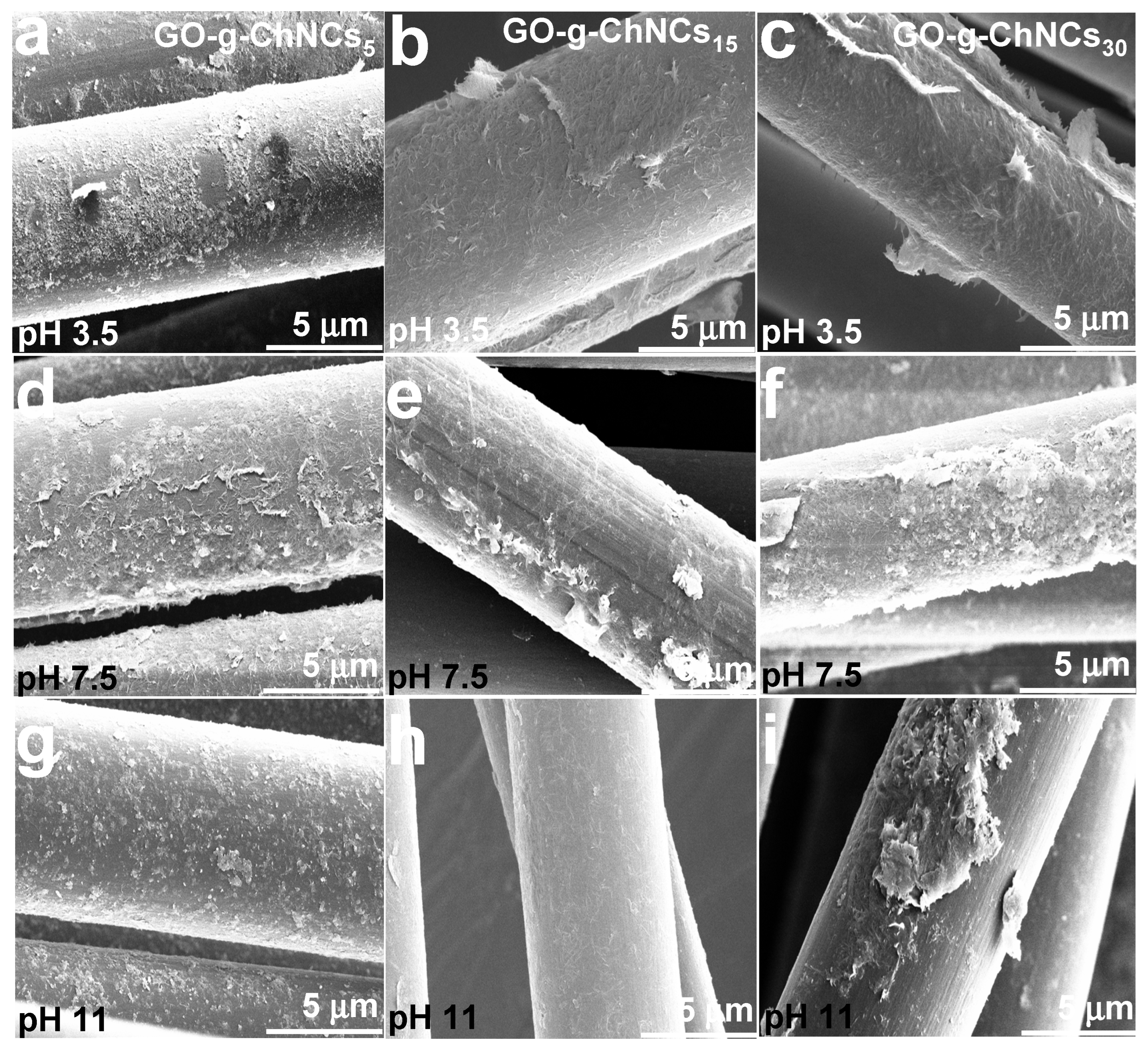
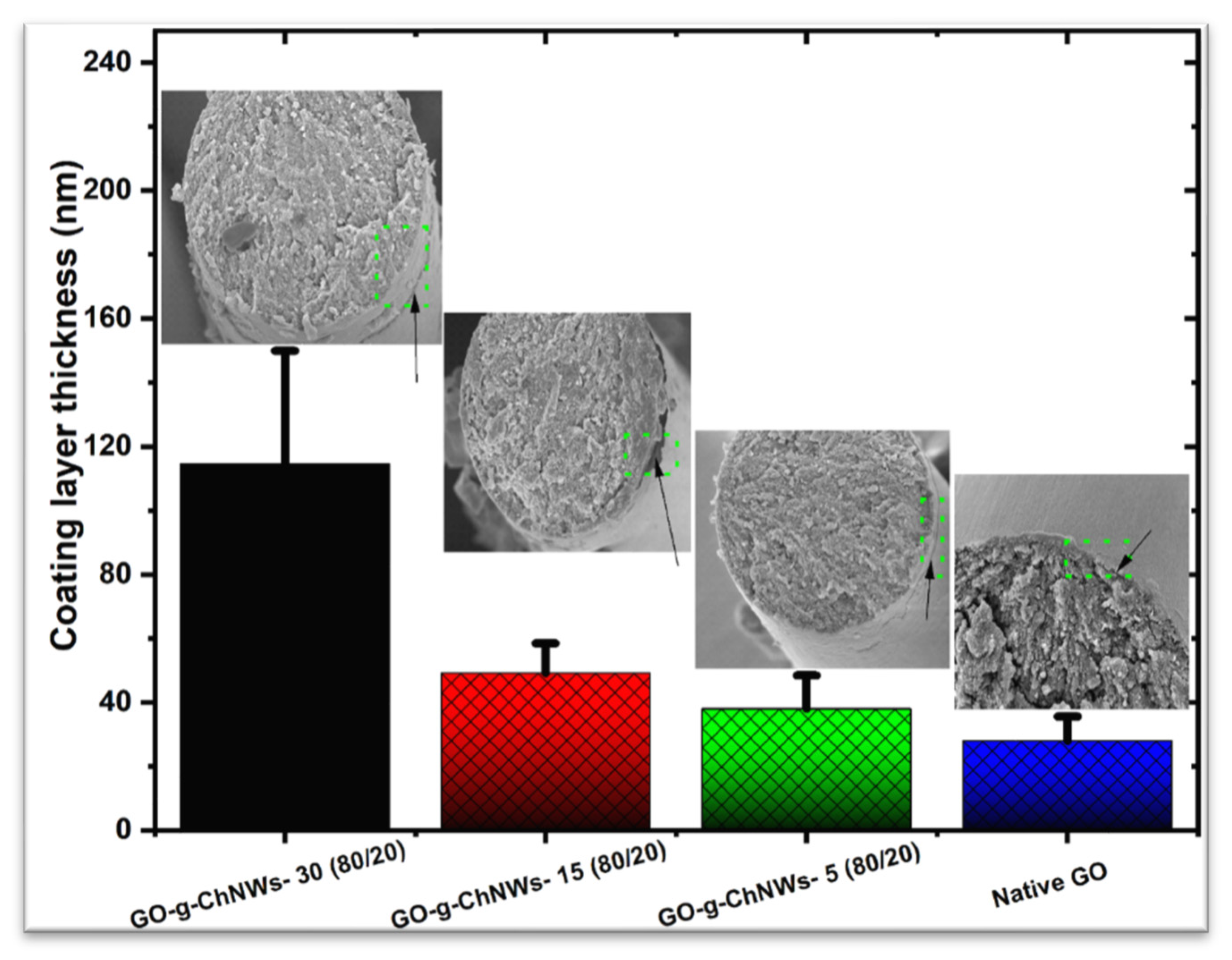
3.2. Effect of the GO/ChNC Adduct Composition and EPD Variations on the Structure of the Coating

The systematic evaluation of the degree of ChNC/GO interactions/bonding on the OCF coating was combined with variations in the EPD conditions to obtain complete information about this process, which, up to now, has not been studied. Figure 5, Figures S3 and S4 follow the marked effect of pH, voltage, and GO/ChNC adduct concentration on the homogeneity and thickness of the coating. Figure 5 shows the important effect of pH; at a lower pH, the OCF was coated with compact homogeneous layers using adducts of all DDAs (Figure 5a–c). At neutral pH, the compact layer of the adducts showed a small aggregation on the OCF surface, which was different for respective DDAs (Figure 5d–f). At pH 11, the thickness of the coating was small compared to pH 3.4, with high aggregation on the OCF surface, mainly for 5 and 30% DDA (Figure 5g–i).
The most homogeneous coating for the GO/ChNC15 adduct at all pHs (Figure 5b,e,h) confirmed the effect of DDA on the structure of the adduct. This fact was also indirectly indicated by the rheology of the water suspensions as well; the differences in G’ of the adducts with different DDAs can be observed (5, 30%, Figure S2b).
Due to the relatively large size of the adducts and the expected high charge density together with the related slower assembly/ordering, unlike the GO-g-polymer chain or polydopamine-coated GO, the best deposition occurred at a lower voltage [46]. As we can see, the lower applied voltage (5 V) led to more homogeneous and compact layers of the GO/ChNC adduct (Figure S3) compared to the highly applied voltage (20 V). Figure S4 shows the effect of adduct concentration on the homogeneity of the OCF coating. As we can see, at lower concentrations, the coating had a heterogeneous distribution on the fiber surface up to (1 mg/mL). A more compact and homogeneous layer was obtained on the OCF surface at higher adduct concentrations.
From Figure 6, it follows that the effect of DDA and, thus, the structure, size, and charge density of the adduct strongly influenced the thickness of the EPD layer; its growing tendency with DDA can be observed, marking its most considerable thickness for 30% DDA with about 120–160 nm.

3.3. Short-Beam Testing (SBS)

Based on the systematic evaluation of EPD conditions on the homogeneity and composition of the coating (see above), we used fibers with the most ‘compact’ coating, i.e., prepared using the GO/ChNC adduct with a concentration of 5 mg/mL, pH ~3.5, voltage of 5 V, and coating time of 10 min for the preparation of the composite short-beam samples. The GO/ChNC ratios were 95/5, 90/10, 80/20, and 50/50, which were used with different DDAs of ChNCs (5, 15, 30%), respectively. The thickness of the coating ranged between 40 and 120 nm (Figure 6); due to the very low effect of the coating thickness in this range on composite parameters, indicated both experimentally and by FEA modeling in our previous paper [46], we did not focus on achieving an identical coating size for the respective adducts in this study. Here, it is important to note that the testing of beam samples made from a ‘bundle’ of fibers, unlike those from plies (laminate samples), has low relevancy to interlaminar shear strength (ILSS). The main purpose of this test was to evaluate the possible unfavorable effect of the coating on basic mechanical properties, which is a limiting factor in most existing solutions using tough coatings [34,53]. At the same time, the first results of a laminate plate made from 30 layers of carbon cloth with an interlayer based on the EPD of (relatively rigid) polydopamine PDA-coated GO indicate a positive effect on delamination resistance. Therefore, we can expect a similar performance for the system studied.
Figure 7 and Table 2 show the results of the SBS testing following the relatively marked effect of DDA of ChNC on the modulus with a strong dependence on the GO/ChNCs ratio, which is reflected in various trends for each composition. In the case of nacre-like composition, that is, 95/5 and 90/10 GO/ChNCs ratios, we can see the most marked modulus increase against the samples with GO-coated fibers. Therefore, with all DDAs, we can undoubtedly expect the formation of favorable brick-and-mortar structures, as reported by others in the case of planar samples (films) [1,3,4,6]. Interestingly, in the case of the 95/5 composition, the modulus decreased with DDA, whereas with the 90/10 ratio, it slightly increased.
For 80/20 and 50/50 GO/ChNC ratios, we can see more marked modulus variations with DDA, that is, the maximal value (exceeding GO) at 15% DDA and 30% DDA, respectively. Especially in the case of 50/50 adducts, the relatively higher content of ChNC amines at the interface with a higher potential for bonding with the matrix may be of importance. This is confirmed by the most marked matrix layer attached to the OCF, which is also coated with the GO/ChNCs30 90/10 adduct (Figure 8). At the same time, the effect of DDA on the short-beam strength (SBS) was less pronounced, with values comparable to those of the GO coating. Slightly higher values against GO were found for 95/5 and 90/10 interlayers containing ChNCs with 15% DDA. This also indicates a similar brick-and-mortar structure. Figure 6 further follows practically no effect of DDA for an 80/20 ratio, while a slight enhancement with 30% DDA for a 50/50 ratio may correspond to the highest potential for bonding with the epoxy matrix (Figure 7). The short-beam testing results indicate that all coating types do not cause an unbearable decrease in composite parameters, so they can be used for further research focused on revealing their effect on delamination resistance using planar multilayered laminates.
Finally, from the observation of fracture surfaces of composites with OCF coated with GO and GO/ChNC 90/10 adducts (Figure 8), there follows practically no matrix presented on the surface of GO-coated OCF whereas the relatively marked matrix layer on GO/ChNC adducts with coated OCF indicate the expected bonding of ChNW amines to the epoxy matrix. An increase in the size and thickness of the attached matrix fragments with ChNC with higher DDAs and, thus, the content of primary amines corresponds to the higher reactivity of primary amines with epoxy groups of the epoxy resin in comparison to secondary amines [54]. At the same time, practically no correspondence of this bonding to SBS strength indicated that the effect of the EPD coating on strength dominated.

4. Conclusions

Chitin nanocrystals (ChNCs) with different DDAs were prepared and used for the preparation of adducts with graphene oxide (GO) at different GO/ChNCs ratios. Their structure was confirmed using different techniques, such as FTIR, XRD, XPS, and DLS. The results indicate that the formation of the GO/ChNC adduct enables an effective electrophoretic coating of the OCFs to form a rigid, tough interface. We have revealed crucial parameters controlling the EPD and homogeneity of the coatings (pH, concentration, voltage) with comparable mechanical parameters, which were also confirmed by the negligible effect of such an interface on the SBS and the modulus of composites. We expect that especially coating with a nacre-like composition, i.e., using the GO/ChNC adduct with a 95/5 and 90/10 ratio, can provide a rigid, tough interface with fair potential to increase delamination resistance; moreover, the low effect of coating composition on mechanical properties of the composite allows its optimization in the case of laminates.

Supplementary Materials

The following supporting information can be downloaded at: https://www.mdpi.com/article/10.3390/jcs8050163/s1, Figure S1: (a) FTIR and (b) XRD of ChNCs with different degree of deacetylation; Figure S2: Rheological characterization of water suspensions (5 mg/mL) of single components and adducts; Figure S3: Effects of voltage and DDA percentages on OCF coating efficiency Conditions: 10 min; 5 mg; pH 3.5, rt.; Figure S4: Effect of concentration of GO/ChNCs30 adduct suspension on OCF coating structure Conditions: 10 min, 5 V, DDA 30%, pH 3.5, different concentration of GO-g-ChNCs (0.01 to 15 mg/mL)., rt.

Author Contributions

Conceptualization, I.K.; Formal analysis, A.M.A.-M. and L.K. (Ludmila Kaprálková); Investigation, A.M.A.-M., R.M.A.-R., L.K. (Lukáš Kalina), V.V., L.K. (Ludmila Kaprálková) and P.N.; Writing—original draft, I.K. and J.J.; Supervision, J.J.; Funding acquisition, I.K. All authors have read and agreed to the published version of the manuscript.

Funding

This work was funded by the Ministry of Education Youth and Sports of the Czech Republic (Grant LUAUS 23004).

Data Availability Statement

The data presented in this study are available in this article.

Conflicts of Interest

The authors declare no conflict of interest.

References

  1. Zhang, Y.; Gong, S.; Zhang, Q.; Ming, P.; Wan, S.; Peng, J.; Jiang, L.; Cheng, Q. Graphene-based artificial nacre nanocomposites. Chem. Soc. Rev. 2016, 45, 2378–2395. [Google Scholar] [CrossRef] [PubMed]
  2. Bonderer, L.J.; Studart, A.R.; Gauckler, L.J. Bioinspired Design and Assembly of Platelet Reinforced Polymer Films. Science 2008, 319, 1069–1073. [Google Scholar] [CrossRef]
  3. Wegst, U.G.K.; Bai, H.; Saiz, E.; Tomsia, A.P.; Ritchie, R.O. Bioinspired structural materials. Nat. Mater. 2015, 14, 23–36. [Google Scholar] [CrossRef] [PubMed]
  4. Wan, S.; Peng, J.; Li, Y.; Hu, H.; Jiang, L.; Cheng, Q. Use of Synergistic Interactions to Fabricate Strong, Tough, and Conductive Artificial Nacre Based on Graphene Oxide and Chitosan. ACS Nano 2015, 9, 9830–9836. [Google Scholar] [CrossRef]
  5. Wang, R.Z.; Suo, Z.; Evans, A.G.; Yao, N.; Aksay, I.A. Deformation mechanisms in nacre. J. Mater. Res. 2001, 16, 2485–2493. [Google Scholar] [CrossRef]
  6. Chen, K.; Tang, X.; Yue, Y.; Zhao, H.; Guo, L. Strong and Tough Layered Nanocomposites with Buried Interfaces. ACS Nano 2016, 10, 4816–4827. [Google Scholar] [CrossRef] [PubMed]
  7. Duan, J.; Gong, S.; Gao, Y.; Xie, X.; Jiang, L.; Cheng, Q. Bioinspired Ternary Artificial Nacre Nanocomposites Based on Reduced Graphene Oxide and Nanofibrillar Cellulose. ACS Appl. Mater. Interfaces 2016, 8, 10545–10550. [Google Scholar] [CrossRef]
  8. Yao, K.; Huang, S.; Tang, H.; Xu, Y.; Buntkowsky, G.; Berglund, L.A.; Zhou, Q. Bioinspired Interface Engineering for Moisture Resistance in Nacre-Mimetic Cellulose Nanofibrils/Clay Nanocomposites. ACS Appl. Mater. Interfaces 2017, 9, 20169–20178. [Google Scholar] [CrossRef]
  9. Li, M.; Wang, X.; Zhao, R.; Miao, Y.; Liu, Z. A novel graphene-based micro/nano architecture with high strength and conductivity inspired by multiple creatures. Sci. Rep. 2021, 11, 1387. [Google Scholar] [CrossRef]
  10. Xiong, R.; Kim, H.S.; Zhang, L.; Korolovych, V.F.; Zhang, S.; Yingling, Y.G.; Tsukruk, V.V. Wrapping Nanocellulose Nets around Graphene Oxide Sheets. Angew. Chem. Int. Ed. 2018, 57, 8508–8513. [Google Scholar] [CrossRef]
  11. Liu, Y.; Yu, S.-H.; Bergström, L. Transparent and Flexible Nacre-Like Hybrid Films of Aminoclays and Carboxylated Cellulose Nanofibrils. Adv. Funct. Mater. 2018, 28, 1703277. [Google Scholar] [CrossRef]
  12. Xu, D.; Wang, S.; Berglund, L.A.; Zhou, Q. Surface Charges Control the Structure and Properties of Layered Nanocomposite of Cellulose Nanofibrils and Clay Platelets. ACS Appl. Mater. Interfaces 2021, 13, 4463–4472. [Google Scholar] [CrossRef] [PubMed]
  13. Laaksonen, P.; Walther, A.; Malho, J.-M.; Kainlauri, M.; Ikkala, O.; Linder, M.B. Genetic Engineering of Biomimetic Nanocomposites: Diblock Proteins, Graphene, and Nanofibrillated Cellulose. Angew. Chem. Int. Ed. 2011, 50, 8688–8691. [Google Scholar] [CrossRef] [PubMed]
  14. Huang, L.; Li, C.; Yuan, W.; Shi, G. Strong composite films with layered structures prepared by casting silk fibroin–graphene oxide hydrogels. Nanoscale 2013, 5, 3780–3786. [Google Scholar] [CrossRef] [PubMed]
  15. Li, M.; Xiong, P.; Mo, M.; Cheng, Y.; Zheng, Y. Electrophoretic-deposited novel ternary silk fibroin/graphene oxide/hydroxyapatite nanocomposite coatings on titanium substrate for orthopedic applications. Front. Mater. Sci. 2016, 10, 270–280. [Google Scholar] [CrossRef]
  16. Zhang, W.; Zheng, K.; Ren, J.; Fan, Y.; Ling, S. Strong, ductile and lightweight bionanocomposites constructed by bioinspired hierarchical assembly. Compos. Commun. 2020, 17, 97–103. [Google Scholar] [CrossRef]
  17. Tran, T.H.; Nguyen, H.-L.; Hwang, D.S.; Lee, J.Y.; Cha, H.G.; Koo, J.M.; Hwang, S.Y.; Park, J.; Oh, D.X. Five different chitin nanomaterials from identical source with different advantageous functions and performances. Carbohydr. Polym. 2019, 205, 392–400. [Google Scholar] [CrossRef] [PubMed]
  18. Abdelrahman, R.; Abdel-Mohsen, A.; Zboncak, M.; Frankova, J.; Lepcio, P.; Kobera, L.; Steinhart, M.; Pavlinak, D.; Spotaz, Z.; Sklenářévá, R.; et al. Hyaluronan biofilms reinforced with partially deacetylated chitin nanowhiskers: Extraction, fabrication, in-vitro and antibacterial properties of advanced nanocomposites. Carbohydr. Polym. 2020, 235, 115951. [Google Scholar] [CrossRef] [PubMed]
  19. Kelnar, I.; Kovářová, J.; Tishchenko, G.; Kaprálková, L.; Pavlová, E.; Carezzi, F.; Morganti, P. Chitosan/Chitin nanowhiskers composites: Effect of plasticisers on the mechanical behaviour. J. Polym. Res. 2015, 22, 5. [Google Scholar] [CrossRef]
  20. Uddin, A.J.; Fujie, M.; Sembo, S.; Gotoh, Y. Outstanding reinforcing effect of highly oriented chitin whiskers in PVA nanocomposites. Carbohydr. Polym. 2012, 87, 799–805. [Google Scholar] [CrossRef]
  21. Wang, C.; Li, J.; Sun, S.; Li, X.; Zhao, F.; Jiang, B.; Huang, Y. Electrophoretic deposition of graphene oxide on continuous carbon fibers for reinforcement of both tensile and interfacial strength. Compos. Sci. Technol. 2016, 135, 46–53. [Google Scholar] [CrossRef]
  22. Jiang, J.; Yao, X.; Xu, C.; Su, Y.; Zhou, L.; Deng, C. Influence of electrochemical oxidation of carbon fiber on the mechanical properties of carbon fiber/graphene oxide/epoxy composites. Compos. Part A Appl. Sci. Manuf. 2017, 95, 248–256. [Google Scholar] [CrossRef]
  23. Wang, C.; Li, Y.; Tong, L.; Song, Q.; Li, K.; Li, J.; Peng, Q.; He, X.; Wang, R.; Jiao, W.; et al. The role of grafting force and surface wettability in interfacial enhancement of carbon nanotube/carbon fiber hierarchical composites. Carbon 2014, 69, 239–246. [Google Scholar] [CrossRef]
  24. Zhang, Q.; Jiang, D.; Liu, L.; Huang, Y.; Long, J.; Wu, G.; Wu, Z.; Umar, A.; Guo, J.; Zhang, X.; et al. Effects of Graphene Oxide Modified Sizing Agents on Interfacial Properties of Carbon Fibers/Epoxy Composites. J. Nanosci. Nanotechnol. 2015, 15, 9807–9811. [Google Scholar] [CrossRef] [PubMed]
  25. Zhang, R.L.; Gao, B.; Ma, Q.H.; Zhang, J.; Cui, H.Z.; Liu, L. Directly grafting graphene oxide onto carbon fiber and the effect on the mechanical properties of carbon fiber composites. Mater. Des. 2016, 93, 364–369. [Google Scholar] [CrossRef]
  26. Qian, H.; Greenhalgh, E.S.; Shaffer, M.S.P.; Bismarck, A. Carbon nanotube-based hierarchical composites: A review. J. Mater. Chem. 2010, 20, 4751–4762. [Google Scholar] [CrossRef]
  27. Li, Y.; Peng, Q.; He, X.; Hu, P.; Wang, C.; Shang, Y.; Wang, R.; Jiao, W.; Lv, H. Synthesis and characterization of a new hierarchical reinforcement by chemically grafting graphene oxide onto carbon fibers. J. Mater. Chem. 2012, 22, 18748–18752. [Google Scholar] [CrossRef]
  28. Asadi, A.; Miller, M.; Moon, R.J.; Kalaitzidou, K. Improving the interfacial and mechanical properties of short glass fiber/epoxy composites by coating the glass fibers with cellulose nanocrystals. Express Polym. Lett. 2016, 10, 587–597. [Google Scholar] [CrossRef]
  29. Uribe, B.E.B.; Chiromito, E.M.S.; Carvalho, A.J.F.; Tarpani, J.R. Low-cost, environmentally friendly route for producing CFRP laminates with microfibrillated cellulose interphase. Express Polym. Lett. 2017, 11, 47–59. [Google Scholar] [CrossRef]
  30. Reale Batista, M.D.; Drzal, L.T. Carbon fiber/epoxy matrix composite interphases modified with cellulose nanocrystals. Compos. Sci. Technol. 2018, 164, 274–281. [Google Scholar] [CrossRef]
  31. Lee, J.U.; Park, B.; Kim, B.-S.; Bae, D.-R.; Lee, W. Electrophoretic deposition of aramid nanofibers on carbon fibers for highly enhanced interfacial adhesion at low content. Compos. Part A Appl. Sci. Manuf. 2016, 84, 482–489. [Google Scholar] [CrossRef]
  32. Zhang, B.; Lian, T.; Shao, X.; Tian, M.; Ning, N.; Zhang, L.; Wang, W. Surface Coating of Aramid Fiber by a Graphene/Aramid Nanofiber Hybrid Material to Enhance Interfacial Adhesion with Rubber Matrix. Ind. Eng. Chem. Res. 2021, 60, 2472–2480. [Google Scholar] [CrossRef]
  33. Wisnom, M.R. The role of delamination in failure of fibre-reinforced composites. Philos. Trans. R. Soc. A Math. Phys. Eng. Sci. 2012, 370, 1850–1870. [Google Scholar] [CrossRef] [PubMed]
  34. Gerard, J.-F. Characterization and role of an elastomeric interphase on carbon fibers reinforcing an epoxy matrix. Polym. Eng. Sci. 1988, 28, 568–577. [Google Scholar] [CrossRef]
  35. Agarwal, B.D.; Bansal, R.K. Effect of an interfacial layer on the properties of fibrous composites: A theoretical analysis. J. Fiber Sci. Technol. 1979, 12, 149–158. [Google Scholar] [CrossRef]
  36. Lee, S.; Ryu, S. Theoretical study of the effective modulus of a composite considering the orientation distribution of the fillers and the weakened interface. Eur. J. Mech. A/Solids 2018, 72, 79–89. [Google Scholar] [CrossRef]
  37. Kausar, A.; Siddiq, M. Epoxy composites reinforced with multi-walled carbon nanotube/poly(ethylene glycol)methylether-coated aramid fiber. J. Polym. Eng. 2016, 36, 465–471. [Google Scholar] [CrossRef]
  38. Yao, X.; Gao, X.; Jiang, J.; Xu, C.; Deng, C.; Wang, J. Comparison of carbon nanotubes and graphene oxide coated carbon fiber for improving the interfacial properties of carbon fiber/epoxy composites. Compos. B Eng. 2018, 132, 170–177. [Google Scholar] [CrossRef]
  39. Wang, P.; Yang, J.; Liu, W.; Tang, X.-Z.; Zhao, K.; Lu, X.; Xu, S. Tunable crack propagation behavior in carbon fiber reinforced plastic laminates with polydopamine and graphene oxide treated fibers. Mater. Des. 2017, 113, 68–75. [Google Scholar] [CrossRef]
  40. De Luca, F.; Sernicola, G.; Shaffer, M.S.P.; Bismarck, A. “Brick-and-Mortar” Nanostructured Interphase for Glass-Fiber-Reinforced Polymer Composites. ACS Appl. Mater. Interfaces 2018, 10, 7352–7361. [Google Scholar] [CrossRef]
  41. Yang, X.; Du, H.; Li, S.; Wang, Z.; Shao, L. Codepositing Mussel-Inspired Nanohybrids onto One-Dimensional Fibers under “Green” Conditions for Significantly Enhanced Surface/Interfacial Properties. ACS Sustain. Chem. Eng. 2018, 6, 4412–4420. [Google Scholar] [CrossRef]
  42. Jin, L.; Zhang, M.; Shang, L.; Liu, L.; Li, M.; Ao, Y. A nature-inspired interface design strategy of carbon fiber composites by growing brick-and-mortar structure on carbon fiber. Compos. Sci. Technol. 2020, 200, 108382. [Google Scholar] [CrossRef]
  43. Wang, J.; Zhou, S.; Huang, J.; Zhao, G.; Liu, Y. Interfacial modification of basalt fiber filling composites with graphene oxide and polydopamine for enhanced mechanical and tribological properties. RSC Adv. 2018, 8, 12222–12231. [Google Scholar] [CrossRef]
  44. Marcano, D.C.; Kosynkin, D.V.; Berlin, J.M.; Sinitskii, A.; Sun, Z.; Slesarev, A.; Alemany, L.B.; Lu, W.; Tour, J.M. Improved Synthesis of Graphene Oxide. ACS Nano 2010, 4, 4806–4814. [Google Scholar] [CrossRef]
  45. Kelnar, I.; Kaprálková, L.; Němeček, P.; Dybal, J.; Abdel-Rahman, R.M.; Vyroubalová, M.; Nevoralová, M.; Abdel-Mohsen, A.M. The Effects of the Deacetylation of Chitin Nanowhiskers on the Performance of PCL/PLA Bio-Nanocomposites. Polymers 2023, 15, 3071. [Google Scholar] [CrossRef]
  46. Kelnar, I.; Kaprálková, L.; Němeček, P.; Janata, M.; Dybal, J.; Svoboda, J.; Padovec, Z.; Abdel-Mohsen, A. Nature-mimicking rigid tough interface in fibrous composites: Effect of polymer/GO combination. Mater. Today Commun. 2022, 33, 104883. [Google Scholar] [CrossRef]
  47. Wu, Q.; Yang, X.; Ye, Z.; Deng, H.; Zhu, J. Dopamine-dependent graphene oxide modification and its effects on interfacial adhesion of carbon fiber composites. Surf. Interfaces 2022, 31, 102086. [Google Scholar] [CrossRef]
  48. Abdel-Mohsen, A.; Abdel-Rahman, R.; Kubena, I.; Kobera, L.; Spotz, Z.; Zboncak, M.; Prikryl, R.; Brus, J.; Jancar, J. Chitosan-glucan complex hollow fibers reinforced collagen wound dressing embedded with aloe vera. Part I: Preparation and characterization. Carbohydr. Polym. 2020, 230, 115708. [Google Scholar] [CrossRef]
  49. Aly, A.S.; Abdel-Mohsen, A.M.; Hrdina, R.; Abou-Okeil, A. Preparation and Characterization of Polyethylene Glycol/Dimethyl Siloxane Adduct and Its Utilization as Finishing Agent for Cotton Fabric. J. Nat. Fibers 2011, 8, 176–188. [Google Scholar] [CrossRef]
  50. Lin, Z.; Ma, Y.; Hu, C.; Zhang, Q. Molecular intercalated graphene oxide with finely controllable interlayer spacing for fast dye separation, Colloids Surf. A: Physicochem. Eng. Asp. 2023, 677, 132437. [Google Scholar] [CrossRef]
  51. Dong, S.; Wang, B.; Liu, D.; He, M.; Chen, M.; Zhao, J.; Jin, W. Tailoring the interlayer channel structure of graphene oxide membrane with conjugated cationic dyes for butanol dehydration. Sep. Purif. Technol. 2023, 325, 124728. [Google Scholar] [CrossRef]
  52. Xu, W.L.; Fang, C.; Zhou, F.; Song, Z.; Liu, Q.; Qiao, R.; Yu, M. Self-Assembly: A Facile Way of Forming Ultrathin, High-Performance Graphene Oxide Membranes for Water Purification. Nano Lett. 2017, 17, 2928–2933. [Google Scholar] [CrossRef]
  53. Zheng, N.; Huang, Y.; Liu, H.-Y.; Gao, J.; Mai, Y.-W. Improvement of interlaminar fracture toughness in carbon fiber/epoxy composites with carbon nanotubes/polysulfone interleaves. Compos. Sci. Technol. 2017, 140, 8–15. [Google Scholar] [CrossRef]
  54. Riccardi, C.C.; Adabbo, H.E.; Williams, R.J.J. Curing reaction of epoxy resins with diamines. J. Appl. Polym. Sci. 1984, 29, 2481–2492. [Google Scholar] [CrossRef]
Figure 1. Representative STEM ((ac,a’c’)), FTIR (d), XRD (e), and his-tograms (f) of ChNCs (see subfigures inside (a’c’) with different DDAs (5, 15, 30%). The dashed areas are magnified in (a’c’).
Jcs 08 00163 g001
Scheme 1. Proposed chemical bonding and interaction between GO and the ChNC and the coating of OCF using the GO/ChNC adduct. (a) Linking GO with ChNCs using EDC/NHS as the crosslinker and catalyst, respectively; (b) the coating of OCF using the GO/ChNC adduct (GO/ChNC adduct@OCF).
Jcs 08 00163 sch001
Figure 2. FTIR (a), XRD (b), and DLS (c) of native components and their adducts.
Jcs 08 00163 g002
Figure 3. Representative SEM images of native ChNCs (a), the GO (c) and GO/ChNCs30 (e) adduct after freeze-drying. Dashed areas are magnified in figures below (b,d,f).
Jcs 08 00163 g003
Figure 4. XPS of OCF, ChNCs, and OCF coated by the GO and GO/ChNCs30 adduct The EPD conditions were as follows: adduct concentration at 5 mg/mL, time of 10 min, voltage at 5 V, pH 3.5 and temperature at 23 °C.
Jcs 08 00163 g004
Figure 5. SEM images showing the effects of pH and DDA percentages on the OCF coating efficiency using the GO/ChNC adduct. EPD proceeded at 23 °C with voltage at 5 V; the adduct concentration was 5 mg/mL, and coating time was 20 min.
Jcs 08 00163 g005
Figure 6. Effects of the DDA of ChNCs on the coating thickness of the GO/ChNC adduct with an 80/20 composition. The EPD conditions were an adduct concentration of 5 mg/mL, time of 10 min, voltage of 5 V, pH 3.5, and temperature of 23 °C.
Jcs 08 00163 g006
Figure 7. Three-point short-beam bending test of composite samples. (ad) Show the effect of CF coating with GO-g-ChNCs with different GO/ChNC ratios on the modulus, (eh) show the analogous effect on SBS (numbers in brackets inside of charts indicate the GO/ChNCs ratio in the GO-g-ChNCs-based coating of CF). Coating conditions: pH ~3.5, voltage 5 V, time 10 min, adduct content of 5 mg/mL.
Jcs 08 00163 g007
Figure 8. SEM of fractured composite with OCF coated with native GO (a,b); the GO/ChNCs5 adduct (c,d); GO/ChNCs15 adduct (e,f) and GO/ChNCs30 adduct (g,h). GO-ChNCs30 (90/10 GO/ChNC ratio in all cases). The dashed areas are magnified in the figures in right.
Jcs 08 00163 g008
Table 1. Composition of GO/ChNC adducts used for CF coating.
NumberGO
(% wt)
ChNCs
(% wt)
DDA of ChNCs *
(%)
Abbreviation
19555GO/ChNCs5 adduct
290105GO/ChNCs5 adduct
380205GO/ChNCs5 adduct
450505GO/ChNCs5 adduct
595515GO/ChNCs15 adduct
6901015GO/ChNCs15 adduct
7802015GO/ChNCs15 adduct
8505015GO/ChNCs15 adduct
995530GO/ChNCs30 adduct
10901030GO/ChNCs30 adduct
11802030GO/ChNCs30 adduct
12505030GO/ChNCs30 adduct
* degree of ChNCs deacetylation.
Table 2. Effect of coating composition on modulus and SBS strength of composite bars. Coating conditions: pH ~3.5, voltage 5 V, time 10 min, adduct content of of 5 mg/mL.
AdductGO
(% wt)
ChNCs
(% wt)
DDA *
(%)
Modulus
(MPa)
SBS
(MPa)
GO100--6640 ± 95051.8 ± 1.1
GO/ChNCs5 95558460 ± 45047.8 ± 1.5
GO/ChNCs15 955158000 ± 5052.2 ± 1.5
GO/ChNCs30 955307750 ± 25047.4 ± 2.0
GO/ChNCs5 901058490 ± 12046.7 ± 4.0
GO/ChNCs15 9010158400 ± 24052.4 ± 2.5
GO/ChNCs30 9010309100 ± 46047.5 ± 1.5
GO/ChNCs5 802057100 ± 15051.8 ± 1.5
GO/ChNCs15 8020158930 ± 85051.9 ± 1.0
GO/ChNCs30 8020306900 ± 10052.1 ± 4.5
GO/ChNCs5 505057250 ± 55053.2 ± 1.0
GO/ChNCs15 5050156750 ± 10054.9 ± 1.0
GO/ChNCs30 5050307890 ± 12057.2 ± 3.0
* degree of ChNCs deacetylation.
Disclaimer/Publisher’s Note: The statements, opinions and data contained in all publications are solely those of the individual author(s) and contributor(s) and not of MDPI and/or the editor(s). MDPI and/or the editor(s) disclaim responsibility for any injury to people or property resulting from any ideas, methods, instructions or products referred to in the content.

