Water Driven Soft Actuator

Department of Informatics, Graduate School of Informatics and Engineering, The University of Electro-Communications, 1-5-1, Chofugaoka, Chofu-shi, Tokyo, 182-8585, Japan
Appl. Syst. Innov. 2018, 1(4), 41; https://doi.org/10.3390/asi1040041
Submission received: 6 September 2018
/
Revised: 11 October 2018
/
Accepted: 17 October 2018
/
Published: 22 October 2018
Abstract
:In this paper, a water driven soft actuator is introduced. Soft actuators driven by various external stimuli, such as air pressure, temperature, pH, electric field, and light have been reported in the past. Although they are very attractive, they often require hard external devices for driving and the response speeds are often slow. The developed water driven actuator was with sodium polyacrylate wrapped by stretchable meshed nylon. Through some experiments, it was confirmed that swell and shrink phenomena of the developed device occur depending on the fluid flow. The phenomena could be found when adequate quantity of sodium polyacrylate was inside of the nylon. The amount of sodium polyacrylate that is required for the phenomenon was investigated. Through the experiments, it was confirmed that the displacement and the response speed of the swell and shrink were large and fast, respectively, in spite of its simple implementation.
1. Introduction
Soft actuators and soft robots are actively studied due to its safety and flexibility in recent years [1]. There are many studies on soft robots aiming to be used in real environments. Soft robots have useful features that are used in real environments, such as high compatibility and safety with the environment [2,3]. Soft robots can enter a narrow space where a hard robot cannot enter as they have flexible structures and can change its own shape due to their softness [4]. It is also hard to damage even if it receives a strong impact, such as falling unlike hard robots [5]. Soft actuators and soft robots are expected to be used in various situations. There are many approaches to achieve soft actuators.
An approach to achieve soft actuation is to employ air pressure. Pneumatic actuator is a well-known actuator using the mechanical constraints. McKibben actuator is an old example of this approach [6,7]. It is composed of rubber tube and non-stretchable mesh and shrinks about 25%. It is used in various scenes, such as worm-like robot [8], quadruped robot [9], humanoid [10,11], and infant robot [12], due to its safeness. Some soft robots are also driven by jamming and pneumatic actuator [13,14]. Soft actuators driven by water pressure are also reported [15]. The response speeds of these actuators are relatively fast. However, these soft actuators require hard pumps as the external equipment to be controlled and these hard devices prevent the robot from becoming completely soft.
Some soft actuators using chemical reaction are also reported. There are many kinds of soft actuators that swell and shrink with various stimuli from external environments. They are categorized as stimuli-responsive polymers (or composite) and they become increasingly important. They are driven by various stimuli, such as temperature [16,17,18], pH [19,20], electric field [21], and light [22]. These types of actuators can swell and shrink depending on the external stimuli without using mechanical parts, such as motors, drive shafts, gears, battery, and so on. We can find many mechanically deformable materials that are composed of stimuli-responsive polymers. The survey on stimuli-responsive polymers on actuation shows some examples [23], such as self-folding liquid crystal elastomer-based actuators, carbon-based nanomaterials, nafion-based actuators, and so on. It categorized them into liquid crystal elastomer-based actuators, dielectric-elastomer-based actuators and ionic-polymer-based actuators. The developed soft actuator is composed of the particle of sodium polyacrylate and nylon pouch. Although sodium polyacrylate is an ionic-polymer and inside the device, the actuation of the device is due to the mechanical structure of the actuator. The proposed actuator is very simple and has some good points compared to existing actuators. The actuator is a kind of water driven soft actuator, and swells and shrinks depending on the amount of the water flow. In spite of its simple implementation, the response time of swell and shrink is very fast like mechanical approaches. The device is a fully soft actuator with safe and human-friendly materials, unlike some soft actuators with dangerous materials. It is expected that passive scale changeable spiles depending on the water flow and actuators for robots driven by the sea tide and rain are potential applications of the proposed devices. The rests of the paper are organized as follows. In Section 2, the chemical feature of the sodium polyacrylate is briefly explained and the design of the proposed actuator is introduced. The mechanism of the swell and shrink of the proposed actuator is also discussed. In Section 3, some of the experimental results are shown to clarify the response speed, the duration rate and the force of the proposed actuator. Conclusions follow in Section 4.
2. Materials and Methods
2.1. Theoretical Analysis
This section gives the feature of sodium polyacrylate and the mechanism of its high water absorption. Its chemical formula is described, as follows:
![Asi 01 00041 i001]()

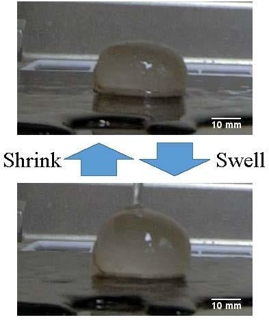
The high water absorption of sodium polyacrylate is due to having a hydrophilic carboxyl group. Figure 1 shows the swell mechanism of sodium polyacrylate. As shown in Figure 1, sodium polyacrylate captures numerous water molecules in the network structure when it is immersed in water. It is a superabsorbent polymer. Some experiments were conducted to check its feature. It could be confirmed that it has the ability to absorb more than 100 times its mass in water. Sodium polyacrylate is known as safe human-friendly material and is widely used for various applications, such as disposable diaper, ice pack, lotion, and gardening. Although the absorption ability of the sodium polyacrylate is very high, the swell is basically irreversible. In other words, once the sodium polyacrylate catches the water, it keeps the water well and it does not release the water normally. Although the feature is good for current applications such as disposable diaper and gardening, it is not suitable for actuators to be used repeatedly. To solve the problem, a developed soft actuator was with particles of sodium polyacrilate wrapped by stretchable meshed nylon. Its design is very simple. Figure 2 shows the fundamental design of the proposed actuator. Unlike normal use of sodium polyacrilate, wet sodium polyacrilate was used for the actuator. Hence, the displacement of the proposed device is not due to that from dry sodium polyacrilate to wet sodium polyacrilate. Figure 3 shows the examples of the motion of the developed device. As shown in Figure 3, the device swells and shrinks depending on the water flow. Unlike normal situation, the process is reversible, that is, the reaction occurs cyclically depending on the water flow. It is considered that this phenomenon is due to the physical constraints of nylon. Here, the mechanism of actuation of the proposed actuator is described. Figure 4 shows the response comparison depending on the quantity of sodium polyacrilate. As shown in Figure 4, the swell and shrink response occur only when the quantity of sodium polyacrilate is adequate. In this case, the quantity of sodium polyacrilate was 16 g in a 3 cm × 3 cm nylon bag. The phenomena do not occur not only when there is little sodium polyacrilate in the nylon but also when there is an excessive quantity of sodium polyacrilate in the nylon.
In this case, the quantity of sodium polyacrilate was 30 g in 3 cm × 3 cm nylon bag (for movies, see Supplementary Information). Empirically, the actuator does not work very well when the nylon is strongly pulled by the sodium polyacrilate. Figure 5 shows the internal structure of the proposed device. As shown in Figure 5, the particles of sodium polyacrylate are fulfilled in the nylon. The quantity of sodium polyacrilate is adequate; they catch the water or keep it among the particles. As the result, the actuator swells. If the quantity of the sodium polyacrilate is very small, the water caught by the sodium polyacrilate also becomes small. The water goes through and the device does not swell. If the quantity of the sodium polyacrilate is too large, as the nylon also expands, the pressure from the nylon also becomes big. The water absorption of sodium polyacrilate is reduced by the pressure, and it becomes difficult for the water to infiltrate the nylon. As the result, the device does not swell. Some parameters are defined to consider the mechanism physically. In Figure 6, P0 represents the atmosphere pressure. Pwater represents the hydraulic pressure. When the water flow starts, Pwater, is from the outside to the inside, while it decreases or becomes from the inside to the outside as the device swells. Psodium is the pressure of the sodium polyacrylate. It is a passive pressure due to the water from the outside. When the water can go outside easier than entering the sodium polyacrylate, the swell of the device stops. Pnylon is the pressure of the nylon. As we used a stretchable nylon, Pnylon is small when the bag does not expand very well. However, when the quantity of the sodium polyacrilate is too large, its effect cannot be ignored. The volume swells stops when all the pressures balances, as follows:
Let Vin and Vout be the volume of the incoming water and the outflowing water per unit time, respectively. The volume difference ΔV is obtained, as follows:
Vout becomes big depending on the swell of the actuator, while Vin is constant when the water flow is constant. Let V0 be the initial volume of the proposed device. The device keeps the water when its volume is V0 due to the feature of sodium polyacrylate. Therefore, Vout can be described as a linear approximation, as follows:
where α is a proportionality constant. Hence, the relation between the time and the volume as a linear time-invariant system and the differential equation can be obtained, as follows:
As the results, V can be described as follows:
where and C2 are constants of integration. Let Veq be the maximal volume when the device is equilibrium condition. When t = 0, the device does not swell. Hence, V(0) = V0. When the device is in equilibrium condition, the volume of the device reaches Veq. Hence, V(∞) = Veq. As the results, the following equation can be obtained.
Hence, the relation between the time and the volume difference should be as shown in Figure 7.
On the other hand, Vout becomes small depending on the shrink of the actuator, while Vin is 0 when the water stops. Hence, the differential equation can be obtained, as follows:
where α is a proportionality constant. It can be solved by the same logic as the swell case. V can be described, as follows:
ere C3 and C4 are constants of integration. When we set the state of the equilibrium condition to t = 0, V(0) = Veq. After sufficient time, the volume of the device returns to V0. Hence,
The time constant τ can be set when a linear time-invariant system is considered. When the water flows to the device, the time constant is described, as follows:
On the other hand, when the water stops, it is described, as follows:
Therefore, the relations between the time and the volume are as shown in Figure 7.
2.2. Experimental Setup
Figure 8 shows the parameters measured by the experiment. hbefore and hafter are defined as the height when the water stops and the height when the water flows, respectively. ∆h is defined as the height difference between hbefore and hafter. To investigate the feature of the proposed device, hbefore change and hafter change, depending on the mass of the sodium polyacrylate, were measured to find the adequate design of the proposed device. The rising time tr and the falling time tf were also measured respectively to clarify the response speed of the proposed actuator. Three types of nylon pouches were prepared. Their sizes were 10 mm × 10 mm, 30 mm × 30 mm, and 50 mm × 50 mm nylon pouch, respectively. Sodium poly-acrylate was injected into them. The nylon was cut from the ladies stockings made by Dinos Cecile Co., Ltd., Tokyo, Japan. The general Young modulus of the nylon is 2–4 GPa [24]. It was sewn into a rectangle after injecting sodium poly-acrylate. The diameter of the particle of the sodium polyacrylate was from 150 to 710 μm. Swell and shrink of the proposed actuator were observed and recorded using a camera (CASIO Corp. EX-ZR1800, Shibuya-ku, Tokyo, Japan).
3. Results
3.1. Experimental Results on Displacement and Response Speed of the Soft Actuator
In the experiment, the displacement is measured depending on the quantity of the sodium polyacrylate. The flowing water was set to 15 mL/s. Before the experiment, the actuator was dipped in water for five minutes. Although it is difficult to say that the device reaches equilibrium state of swelling, the swell rate after five minutes becomes much smaller than that when the device was just put in water. Figure 9, Figure 10 and Figure 11 show the relation between the mass of the sodium polyacrylate in the nylon and the height of the actuator when 1 cm × 1 cm, 3 cm × 3 cm, and 5 cm × 5 cm nylon bags, respectively. The weight of sodium polyacrilate represents the weight of wet sodium polyacrilate through the paper. In Figure 9, the heights before and after pouring water were equal when the mass of the proposed actuator was 0.1, 1.1 and 1.5 g. As shown in Figure 9, Figure 10 and Figure 11, a similar tendency could be found in spite of using different size of actuators. The height difference ∆h is very small when the mass of the sodium polyacrylate is very small and very large. For example, when the mass is around 10 to 20 g in 3 cm × 3 cm, the swell and shrink become large. The displacement rate is around 40% to 50%. The time constant were also measured to check the response speed. The water was poured on the actuator and the movement of the actuator was measured by using image analysis. The time constant was around 0.03 to 0.07 s in both cases. The response speed is very fast when compared to typical soft actuators (for movies, see Supplementary Information).
3.2. Experimental Results on Water Flow and Force of the Soft Actuator
Some experiments were conducted to check the relation between the water flow and the force. 3 cm × 3 cm the nylon bag were prepared and sodium polyacrilate was injected. The quantity of sodium polyacrilate in 3 cm × 3 cm the nylon bag was set to 16 g. The actuator was placed against a wall. A tension gauge was placed against it. In the experiments, the water flow was changed and the force depending the water flow was checked. Figure 12 shows the relation between the water flow and the force. As shown in Figure 12, the force basically increased when the water flow increased. Demonstration experiments were also conducted to show the potential of the proposed actuator. In this experiment, the actuator was set against a wall and a 100 g object was placed against it. The quantity of sodium polyacrilate was 16 g in 3 cm × 3 cm the nylon bag. Figure 13 shows the demonstration in which the actuator moves the 100 g object. It moves about 5 mm, which corresponds to the displacement of the actuator. To clarify that the work is due to the developed actuator, the results of comparison experiment is also shown. In the comparison experiment, the device was taken out and the water was just poured to the place where the device was set. Although we changed the strength of the water flow, the object did not move, as shown in Figure 14 (for movies, see Supplementary Information).
3.3. Experimental Results on Water Flow and Path through the Soft Actuator
Another concept of usage of the proposed device was shown in this section. Figure 15 shows the concept of this application. The supposed application is a kind of scale changeable spile. As shown in Figure 15, the device is set inside the tube in the current scenario. To fix it, the mesh to keep the device will also be set. When the amount of water flow is low, the device does not swell very much and it is expected that the water goes through the tube. On the other hand, when the amount of water flow is high, the device swells and it becomes like a spile in the tube. As the results, it is expected that the water does not go through the tube. Some experiments were conducted to check whether this application is possible. The hold with 3 cm radius hole was set on its top and the hole was covered with mesh. Then, the circular nylon bag with radius 3 cm and with 9 g sodium polyacrilate was set on the hole covered with mesh. The experiments were to check how much the water went into the hold depending on the water flow. Through the experiments, the water hardly entered the hold (≤10 mL/min) when the amount of the water flow is high, while the water entered the hold (100 mL/min) when the amount of the water flow is low. Figure 16 shows the examples of the experiments. As shown in Figure 16, in both cases, the hole was covered with the device. However, the water went into the hold through the interspace when the amount of the water flow was low, while the water could not go into the hold when the amount of the water flow was high, as the device swelled and the interspace was blocked (for movies, see Supplementary Information). It was also confirmed that the water was hard to pass through the proposed device through the experiment. The results support the possibility that the proposed device can be applied to scale changeable spiles.
4. Conclusions
In this paper, a simple water driven soft actuator was introduced. Although the device design is very simple, the displacement is around 40% to 50%. The time constants were within 0.1 s.
The displacement and response speed are large and fast when compared to typical soft actuators. The force of the actuator is measured and a demonstration was shown to clarify that the proposed device can move the object as an actuator. Another scenario of the proposed device as a scale changeable spile was also shown and simple experimental results were given. The constituent material of the proposed actuator is safe and high affinity for humans as it is composed only of the sodium polyacrylate and nylon. The cost required for that actuator is less than 10 cents per an actuator. It is a very inexpensive actuator when compared to other actuators. Through the experiments, The feature and the potential of the actuator could be confirmed. I would like to study more deeply about the applications as scale changeable spiles depending on the water flow. I also would like to develop robots that are driven by the sea tide and rain for future. Theoretical analyses of the proposed actuator should also be done for further studies.
Supplementary Materials
The following are available online at https://www.mdpi.com/2571-5577/1/4/41/s1, Video S1: Movie-adequate.avi, Video S2: Movie-none.avi, Video S3: Movie-excessive.avi, Video S4: Movie-demonstration.avi, Video S5: Movie-demonstration2.avi, Video S6: Movie-spile1.avi, Video S7: Movie-spile2.avi.
Funding
This research received no external funding.
Conflicts of Interest
The author declares no conflict of interest.
References
- Kim, S.; Laschi, C.; Trimmer, B. Soft robotics: A bioinspired evolution in robotics. Trends Biotechnol. 2013, 31, 287–294. [Google Scholar] [CrossRef] [PubMed]
- Jayaram, K.; Full, R.J. Cockroaches traverse crevices, crawl rapidly in confined spaces, and inspire a soft, legged robot. PNAS 2016, 113, E950–E957. [Google Scholar] [CrossRef] [PubMed]
- Brown, E.; Rodenberg, N.; Amend, J.; Mozeika, A.; Steltz, E.; Zakin, M.R.; Lipson, H.; Jaeger, H.M. Universal robotic gripper based on the jamming of granular material. PNAS 2010, 107, 18809–18814. [Google Scholar] [CrossRef] [Green Version]
- Hawkes, E.W.; Blumenschein, L.H.; Greer, J.D.; Okamura, A.M. A soft robot that navigates its environment through growth. Sci. Rob. 2017, 2. [Google Scholar] [CrossRef]
- Nishikawa, Y.; Matsumoto, M. Lightweight indestructible soft robot. IEEJ Trans. Electr. Electr. Eng. 2018, 13, 652–653. [Google Scholar] [CrossRef]
- Tondu, B.; Lopez, P. Modeling and control of McKibben artificial muscle robot actuators. IEEE Control Syst. 2000, 20, 15–38. [Google Scholar] [CrossRef]
- Tondu, B. Modelling of the McKibben artificial muscle: A review. J. Intell. Mater. Syst. Struct. 2012, 23, 225–253. [Google Scholar] [CrossRef]
- Boxerbaum, A.; Chiel, H.J.; Quinn, R.D. A New Theory and Methods for Creating Peristaltic Motion in a Robotic Platform. In Proceedings of the IEEE International Conference on Robotics and Automation, Anchorage, AK, USA, 3–8 May 2010; pp. 1221–1227. [Google Scholar] [CrossRef]
- Rosendo, A.; Nakatsu, S.; Narioka, K.; Hosoda, K. Pneupard: A biomimetic musculoskeletal approach for a feline-inspired quadruped robot. In Proceedings of the IEEE/RSJ International Conference on Intelligent Robots and Systems, Tokyo, Japan, 3–7 November 2013; pp. 1452–1457. [Google Scholar] [CrossRef]
- Niiyama, R.; Nagakubo, A.; Kuniyoshi, Y. Mowgli: A Bipedal Jumping and Landing Robot with an Artificial Musculoskeletal System. In Proceedings of the IEEE/RSJ International Conference on Intelligent Robots and Systems, Roma, Italy, 10–14 April 2007; pp. 2546–2551. [Google Scholar] [CrossRef]
- Niiyama, R.; Nishikawa, S.; Kuniyoshi, Y. Athlete Robot with Applied Human Muscle Activation Patterns for Bipedal Running. In Proceedings of the IEEE-RAS International Conference on Humanoid Robots, Nashville, TN, USA, 6–8 December 2010; pp. 498–503. [Google Scholar]
- Norioka, K.; Hosoda, K. Motor Development of an Pneumatic Musculoskeletal Infant Robot. In Proceedings of the IEEE International Conference on Robotics and Automation, Shanghai, China, 9–13 May 2011; pp. 963–968. [Google Scholar] [CrossRef]
- Steltz, E.; Mozeika, A.; Rodenberg, N.; Brown, E.; Jaeger, H.M. JSEL: Jamming Skin Enabled Locomotion. In Proceedings of the IEEE/RSJ International Conference on Intelligent Robots and Systems, St. Louis, MO, USA, 11–15 October 2009; pp. 5672–5677. [Google Scholar] [CrossRef]
- Shepherd, R.F.; Ilievski, F.; Choi, W.; Morin, S.A.; Stokes, A.A.; Mazzeo, A.D.; Chen, X.; Wang, M.; Whitesides, G.M. Multigait soft robot. PNAS 2011, 108, 20400–20403. [Google Scholar] [CrossRef] [PubMed] [Green Version]
- Tolley, M.T.; Shepherd, R.F.; Karpelson, M.; Bartlett, N.W.; Galloway, K.C.; Wehner, M.; Nunes, R.; Whitesides, G.M.; Wood, R.J. An untethered jumping soft robot. In Proceedings of the IEEE/RSJ International Conference on Intelligent Robots and Systems, Chicago, IL, USA, 14–18 September 2014; pp. 561–566. [Google Scholar] [CrossRef]
- Li, S.; Daniel, M.V.; Rus, D.; Wood, R.J. Fluid-driven origami-inspired artificial muscles. PNAS 2017. [Google Scholar] [CrossRef] [PubMed]
- Yamagiwa, K.; Katoh, M.; Yoshida, M.; Ohkawa, A.; Ichijo, H. Temperature-Swing Column Adsorption of Nonionic Surfactant with Poly(vinylmethylether) Gel. J. Chem. Eng. Jpn. 2001, 34, 1317–1320. [Google Scholar] [CrossRef]
- Kim, Y.S.; Liu, M.; Ishida, Y.; Ebina, Y.; Osada, M.; Sasaki, T.; Hikima, T.; Takata, M.; Aida, T. Thermoresponsive actuation enabled by permittivity switching in an electrostatically anisotropic hydrogel. Nat. Mater. 2015, 14, 1002–1007. [Google Scholar] [CrossRef] [PubMed]
- Brannon-Peppas, L.; Peppas, N.A. Dynamic and equilibrium swelling behaviour of pH-sensitive hydrogels containing 2-hydroxyethyl methacrylate. Biomaterials 1990, 11, 635–644. [Google Scholar] [CrossRef]
- Fundueanu, G.; Constantin, M.; Bucatariu, S.; Ascenzi, P. pH/thermo-responsive poly(N-isopropylacrylamide-co-maleic acid) hydrogel with a sensor and an actuator for biomedical applications. Polymer 2017, 110, 177–186. [Google Scholar] [CrossRef]
- Osada, Y.; Okazaki, H.; Hori, H. A polymer gel with electrically driven mobility. Nature 1992, 355, 242–244. [Google Scholar] [CrossRef]
- Yu, Y.; Nakano, M.; Ikeda, T. Photomechanics: Directed bending of a polymer film by light. Nature 2003, 425, 145. [Google Scholar] [CrossRef] [PubMed]
- Zhang, Q.M.; Serpe, M.J. Stimuli-Responsive Polymers for Actuation. Chemphyschem 2017. [Google Scholar] [CrossRef] [PubMed]
- Available online: https://www.engineeringtoolbox.com/ (accessed on 9 October 2018).
Figure 1.
Water absorption mechanism of sodium polyacrylate.
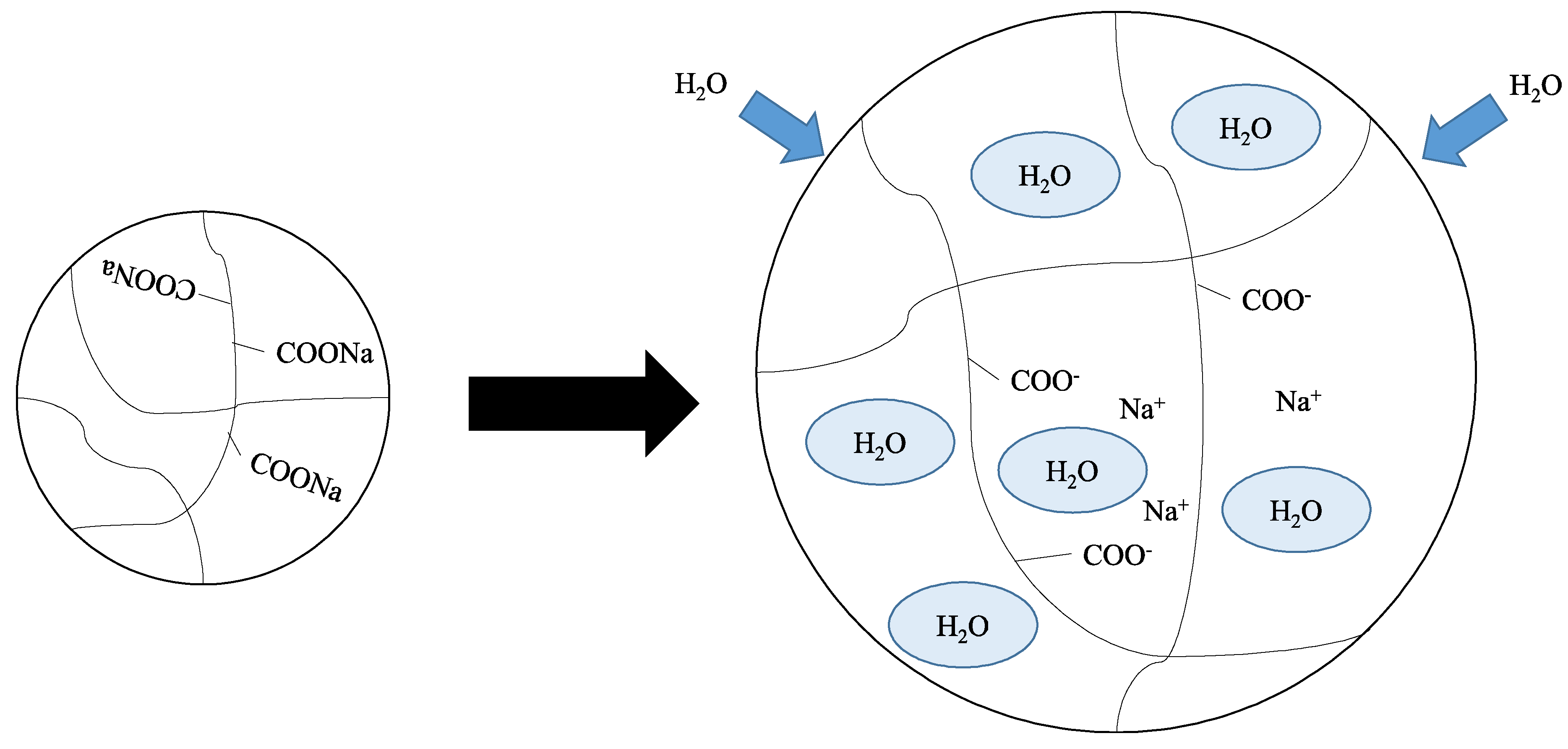
Figure 2.
A basic design of water driven soft actuator; The sodium polyacrylate is wrapped by the stretchable meshed nylon. If the quantity of the sodium polyacrylate is adequate, the device can swell and shrink depending on the water flow.
Figure 2.
A basic design of water driven soft actuator; The sodium polyacrylate is wrapped by the stretchable meshed nylon. If the quantity of the sodium polyacrylate is adequate, the device can swell and shrink depending on the water flow.

Figure 3.
Example of the proposed actuator when the water flows to the device and stops.

Figure 4.
Response comparison depending on the quantity of sodium polyacrilate (for movies, see Supplementary Information).
Figure 4.
Response comparison depending on the quantity of sodium polyacrilate (for movies, see Supplementary Information).

Figure 5.
Internal structure of actuator.
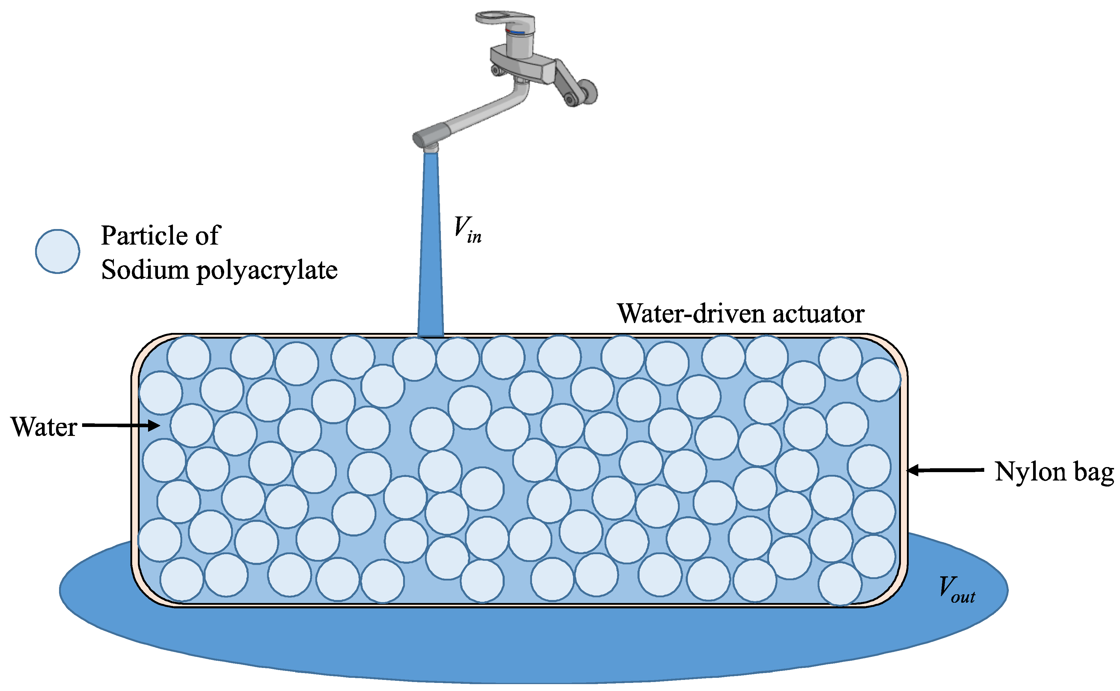
Figure 6.
Basic concept of the actuation mechanism of the proposed actuator.

Figure 7.
Relation between the time and V modeled by a linear time-invariant system when the actuator swells and shrinks, respectively. (a) Relation between the time and V when the actuator swells; (b) Relation between the time and V when the actuator shrinks.
Figure 7.
Relation between the time and V modeled by a linear time-invariant system when the actuator swells and shrinks, respectively. (a) Relation between the time and V when the actuator swells; (b) Relation between the time and V when the actuator shrinks.
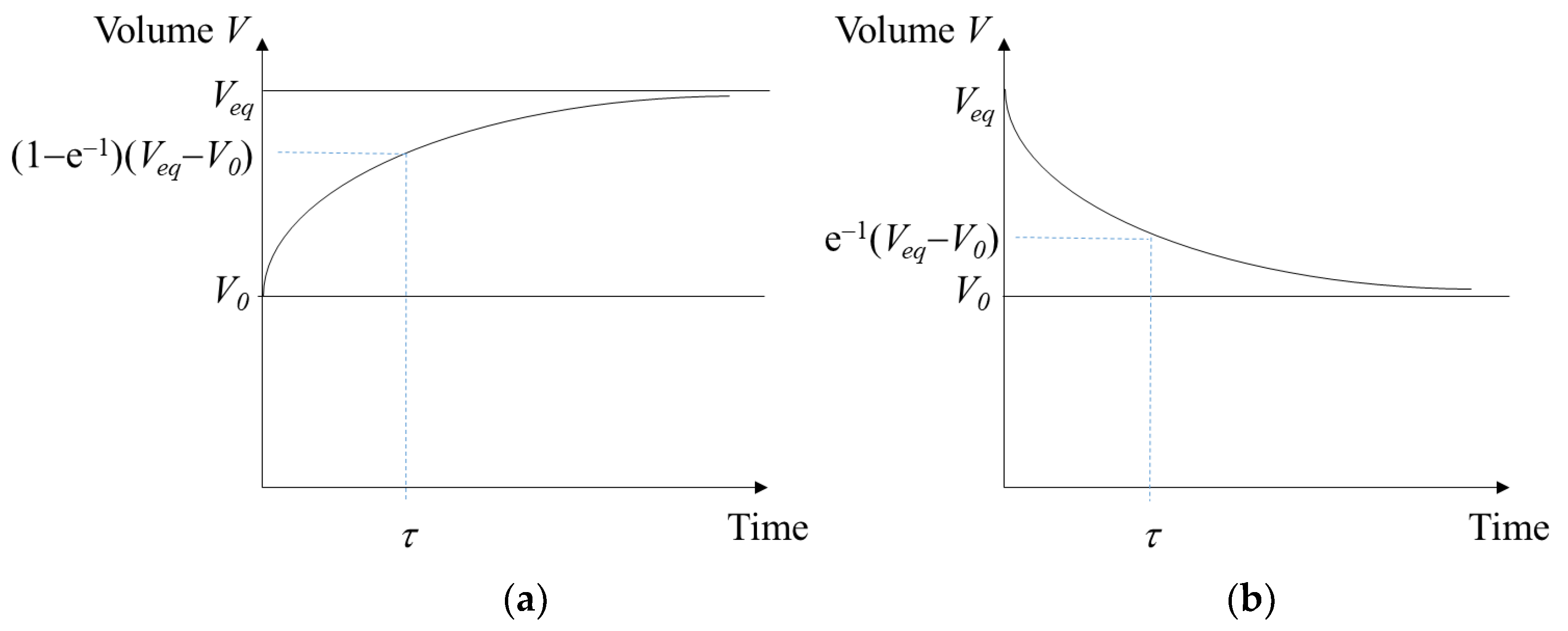
Figure 8.
Fundamental parameter of the proposed actuator to be measured in the experiments.

Figure 9.
Fundamental parameter of the proposed actuator to be measured in the experiments when 1 cm × 1 cm nylon bag was used.
Figure 9.
Fundamental parameter of the proposed actuator to be measured in the experiments when 1 cm × 1 cm nylon bag was used.

Figure 10.
Fundamental parameter of the proposed actuator to be measured in the experiments when 3 cm × 3 cm nylon bag was used.
Figure 10.
Fundamental parameter of the proposed actuator to be measured in the experiments when 3 cm × 3 cm nylon bag was used.

Figure 11.
Fundamental parameter of the proposed actuator to be measured in the experiments when 5 cm × 5 cm nylon bag was used.
Figure 11.
Fundamental parameter of the proposed actuator to be measured in the experiments when 5 cm × 5 cm nylon bag was used.
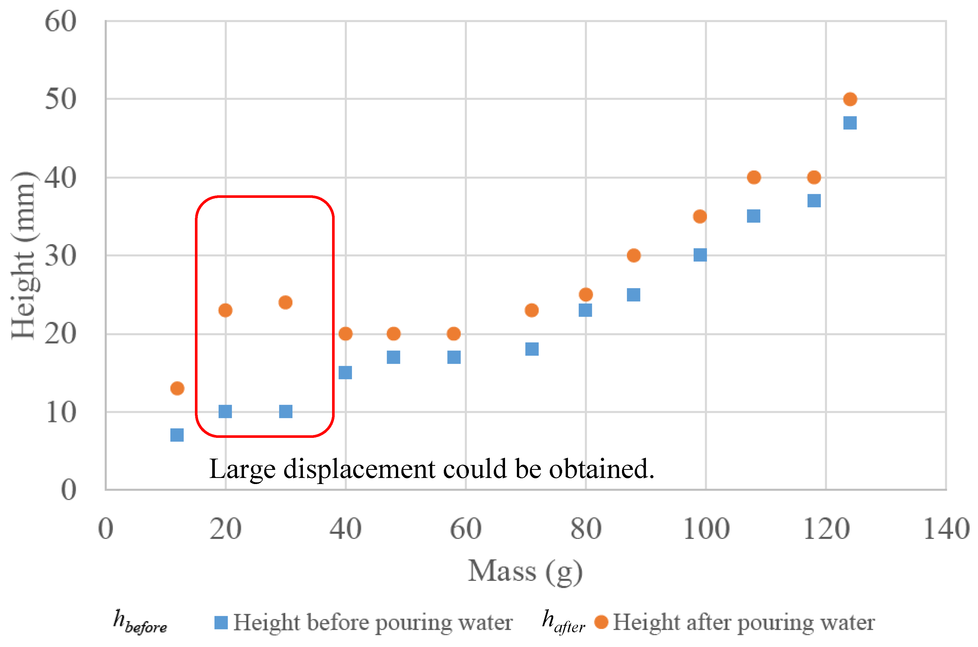
Figure 12.
Fundamental parameter of the proposed actuator to be measured in the experiments when 3 cm × 3 cm nylon bag was used. The quantity of sodium polyacrilate was set to 16 g.
Figure 12.
Fundamental parameter of the proposed actuator to be measured in the experiments when 3 cm × 3 cm nylon bag was used. The quantity of sodium polyacrilate was set to 16 g.

Figure 13.
Demonstration in which an actuator moves a 100 g object (for movies, see Supplementary Information).
Figure 13.
Demonstration in which an actuator moves a 100 g object (for movies, see Supplementary Information).

Figure 14.
Demonstration in which the water does not move a 100 g object (for movies, see Supplementary Information).
Figure 14.
Demonstration in which the water does not move a 100 g object (for movies, see Supplementary Information).

Figure 15.
Another application of the proposed device as a scale changeable spile.

Figure 16.
Another application of the proposed device as a scale changeable spile (for movies, see Supplementary Information).
Figure 16.
Another application of the proposed device as a scale changeable spile (for movies, see Supplementary Information).

© 2018 by the author. Licensee MDPI, Basel, Switzerland. This article is an open access article distributed under the terms and conditions of the Creative Commons Attribution (CC BY) license (http://creativecommons.org/licenses/by/4.0/).
Share and Cite
MDPI and ACS Style
Matsumoto, M. Water Driven Soft Actuator. Appl. Syst. Innov. 2018, 1, 41. https://doi.org/10.3390/asi1040041
AMA Style
Matsumoto M. Water Driven Soft Actuator. Applied System Innovation. 2018; 1(4):41. https://doi.org/10.3390/asi1040041
Chicago/Turabian StyleMatsumoto, Mitsuharu. 2018. "Water Driven Soft Actuator" Applied System Innovation 1, no. 4: 41. https://doi.org/10.3390/asi1040041