Low-Energy State Electron Beam in a Uniform Channel


Department of Electrical and Computer Engineering, University of New Mexico, Abuquerque, NM 87131-0001, USA
*
Author to whom correspondence should be addressed.
Plasma 2019, 2(2), 222-228; https://doi.org/10.3390/plasma2020016
Submission received: 21 January 2019
/
Revised: 20 May 2019
/
Accepted: 21 May 2019
/
Published: 27 May 2019
(This article belongs to the Special Issue High-Power Microwave and Plasma Interactions)
Abstract
:In our earlier work, we showed that a low-energy state of an electron beam exists in a nonuniform channel between two virtual cathodes in a magnetron with diffraction output, which consists of three uniform sections with increasing radius. A uniform axial magnetic field fills the interaction space. This led to magnetron operation with >90% efficiency when combined with a magnetic mirror field at the output end. In this present paper, we show that a low-energy state of an electron beam can be realized in a uniform channel in which an increasing magnetic field is used in order to create a magnetic mirror at the output end. We consider two cases, one where the injected beam current slightly exceeds the space-charge-limiting current and the other where the injected beam current greatly exceeds the space-charge-limiting current. On the time scale of relevance to planned experiments (∼30 ns), when the injected current slightly exceeds the space-charge-limiting current a stationary virtual cathode forms and when the injected current greatly exceeds the space-charge-limiting current the virtual cathode oscillates back and forth.
1. Introduction
In our earlier work using the MAGIC particle-in-cell (PIC) code [1], we showed that a low-energy state of an electron beam exists in a nonuniform channel between two virtual cathodes (VCs) in a magnetron with diffraction output (MDO), which consists of three uniform sections (Figure 1) with increasing radius [2,3]. A uniform axial magnetic field fills the interaction space. The first VC (VC1) occurs when the electron beam with radius cm propagates from a tubular cathode along a strong longitudinal magnetic field into a tube with radius cm, exceeding the space-charge-limited current in the larger radius tube with radius cm. The second virtual cathode (VC2) occurs as the electron beam exits the tube with radius and enters a larger radius tube with radius cm. The formation of a potential well with voltage , which is analogous to the low-energy state of electrons, is very useful to achieve high electronic efficiency in an MDO. This led to the operation of an MDO with efficiency >90% in PIC simulations, a record for a high power microwave (HPM) source [4].
This earlier result motivated us to consider whether such a low-energy state of electrons can occur in a uniform channel. In order to form such a low-energy state of electrons, the participation of reflected electrons or oppositely moving electrons (two-stream motion) is necessary. Electron reflections can take place for a uniform tube as well. First, instead of VC1 in the uniform tube, a thin-walled tubular cathode can be employed because Fedosov’s [5,6] current is realized in the uniform channel. Fedosov’s current is given by
where , , m is the electron mass, e is the electron charge, c is the light speed, is the cathode radius (1.0 cm), is the anode radius, is the anode potential, and is the relativistic Lorentz factor corresponding to the anode potential. An electron beam with a low-energy state has Lorentz factor [7], where and v is the total electron velocity.
In addition, instead of VC2 in a uniform magnetic field, we use an increasing magnetic field distribution , where is the initial axial coordinate of the interaction space, to achieve the magnetic mirror effect.
2. Conditions for Electron Reflection in a Uniform Channel
Consider a uniform-radius channel. The radius of the tubular explosive emission cathode in a uniform magnetic field is cm. Electrons start from the cathode with velocity . Let us show that is also the condition for electron reflection from the downstream magnetic mirror [8]. In order to reflect all electrons the total electron momentum
can be represented as
where , , is the transverse velocity of electrons, , , and is the longitudinal velocity of electrons. According to the adiabatic invariant
as the magnetic field B increases, the transverse momentum increases up to the total momentum
so that the longitudinal momentum decreases to
when all electrons are reflected. Equation (6) or is the condition for reflection of electrons [8]. Let us assume . Then, from Equation (3) it follows that becomes imaginary, which is impossible for motion. The low-energy state of electrons appears between the first VC and the magnetic mirror.
3. Appearance of a VC in a Uniform Channel—Two Cases
In the increasing magnetic field distribution we introduced earlier, a VC appears when the beam current exceeds the axial space-charge-limited current, given by [9]
Equation (7) is the condition for the appearance of a VC and we assume that this condition is also correct for the non-stationary case.
The PIC code ICEPIC [10] was used to perform the simulations presented in this paper. ICEPIC simulations show that when only slightly exceeds , a stationary VC appears with the low-energy state of electrons in the two-stream electron beam between the VC and the magnetic mirror. When considerably exceeds , a VC appears and oscillates back and forth on the time scale of relevance to planned experiments (∼30 ns). We present details below.
We first consider the case when only slightly exceeds . The parameters of the simulations for this case are summarized in Table 1.
Table 2 provides the parameters of the simulations for the case when significantly exceeds .
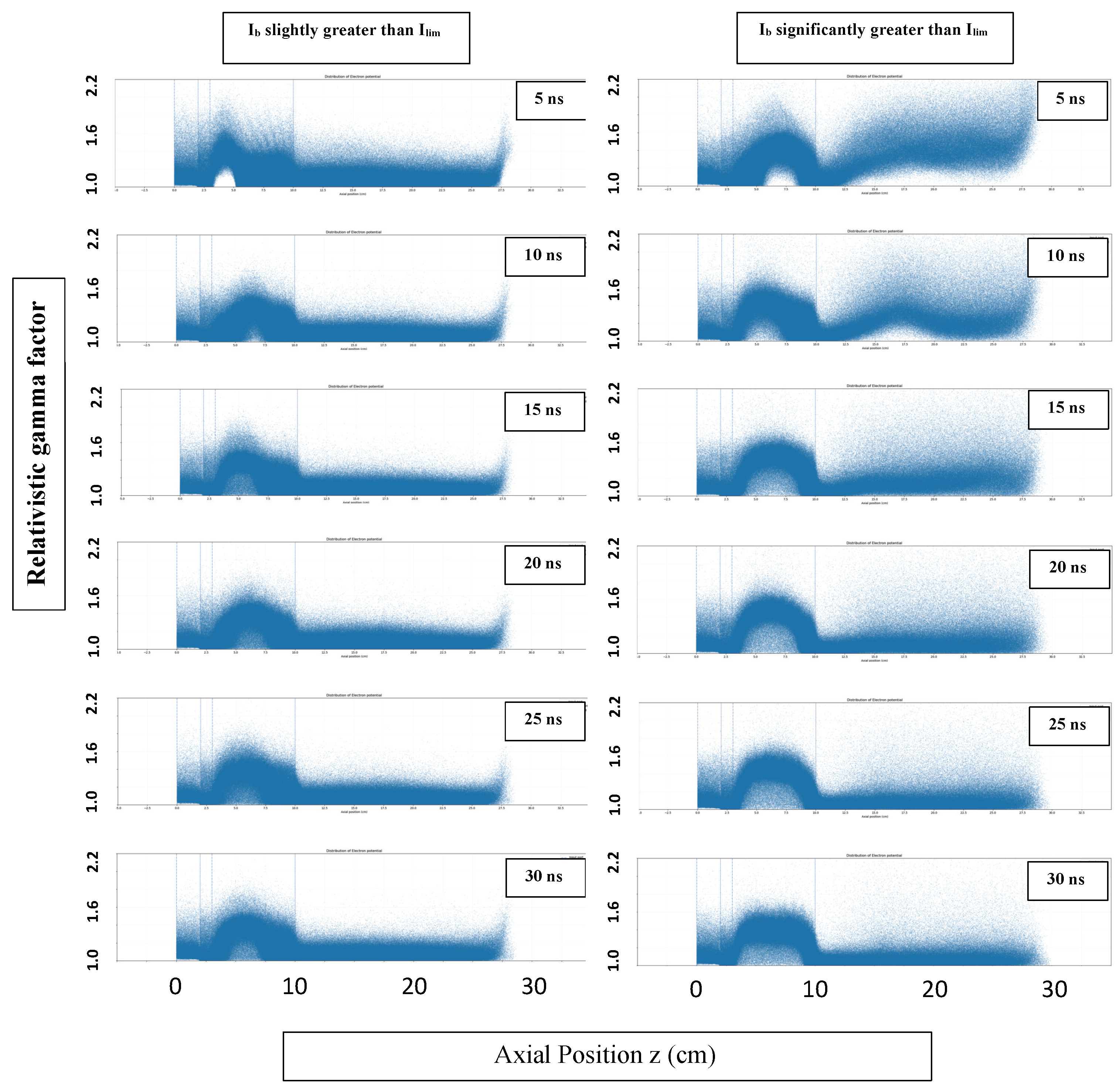
Figure 2 presents a summary of the simulations for the two cases under consideration. The left column shows VC formation in the electron beam in an increasing magnetic field with slightly greater than . The right column shows VC formation in the electron beam in an increasing magnetic field with significantly greater than . The duration of the simulations was 32 ns. Shown are snapshots of as a function of z for the two cases at 5 ns, 10 ns, 15 ns, 20 ns, 25 ns, and 30 ns.
When considerably exceeds , a movable VC appears with the low-energy state electrons after the VC, which confirms the results published earlier in [11]. Explosive electron emission takes place from the cathode, on the surface of which , and then electrons are accelerated in the electric field that is associated with the applied voltage, and then total reflection occurs from the magnetic mirror. In Figure 3, which is an earlier simulation performed using MAGIC, corresponds to electron propagation from the cathode (left) to the VC (right), whereas corresponds to electron propagation in the opposite direction. The left point corresponds to reflection from the immovable physical cathode, whereas the right point corresponds to reflection from the VC, which can be a movable VC. For the movable VC, PIC simulations provide an estimate of the VC velocity, which is about .
The space charge of the electrons that reflect from the mirror and approach the cathode partially suppresses subsequent electron emission, but the continued emission adds additional electrons to the flow that reflects from the physical cathode. Therefore, the electron flow becomes denser and slower in the fixed electric field. The next time this denser flow reflects from the mirror, it will further suppress electron emission at the cathode. This process will continue up until the state when the space charge of the electron flow completely suppresses electron emission from the cathode and the reflection coefficients (from the cathode and the turning point in the mirror) become unity.
4. Discussion and Conclusions
In this study, we used ICEPIC PIC code simulations to analyze the low-energy state of an electron beam in a uniform channel. A uniform axial magnetic field fills the interaction space. An explosive emission cathode is used to generate a thin-walled tubular beam and a magnetic mirror field described by , where is the initial axial coordinate of the interaction space, is used at the output end. Simulation results show that when the beam current slightly exceeds the space-charge-limited current , a stationary VC appears with the low-energy state of electrons in the interaction region between the VC and the magnetic mirror. When the beam current considerably exceeds the space-charge-limited current , a movable VC appears with the low-energy state electrons after the VC on the time scale of relevance to planned experiments (∼30 ns). Electrons reflected from the downstream mirror travel upstream and partially suppress electron emission. The continued electron emission increases the electron density in the flow and this process continues until electron emission is completely suppressed at the cathode and the final low-energy state of the electrons is achieved.
Experiments are planned at the University of New Mexico to first validate the MDO driven by a VC (summer 2019), and then exploit the MDO with VC and magnetic mirror (2020–2021).
Supplementary Materials
The following are available online at https://www.mdpi.com/2571-6182/2/2/16/s1, Video S1: S-band VC r = 1.7 cm (slightly exceeds), Video S2: S-band VC r = 3 cm (significantly exceeds).
Author Contributions
M.F. and E.S. conceived the idea of employing the magnetic mirror effect. M.F. performed the earlier MAGIC simulations. D.A. and A.K. performed the ICEPIC simulations presented here. E.S. leads the group and wrote the paper.
Funding
This research was supported by ONR Grants N00014-16-1-2352 and N00014-19-1-2155.
Acknowledgments
One of the authors (M.F.) wishes to thank M.B. Goykhman, A.V. Gromov, N.F. Kovalev, and A.V. Palitsin (Institute of Applied Physics, Nizhny Novgorod, Russia) for useful discussions.
Conflicts of Interest
The authors declare no conflict of interest.
References
- Goplen, B.; Ludeking, L.; Smithe, D.; Warren, G. User configurable MAGIC code for electromagnetic PIC calculations. Comput. Phys. Commun. 1995, 87, 54–86. [Google Scholar] [CrossRef]
- Fuks, M.; Prasad, S.; Schamiloglu, E. Efficient magnetron with virtual cathode. IEEE Trans. Plasma Sci. 2016, 44, 1298–1302. [Google Scholar] [CrossRef]
- Schamiloglu, E.; Fuks, M.I.; Koronovskii, A.A.; Kurkin, S.A. Efficient Relativistic Magnetron with Lengthy Virtual Cathode Formed using the Magnetic Mirror Effect (Keynote Address). In Proceedings of the IVEC 2017, London, UK, 24–26 April 2017. [Google Scholar]
- Benford, J.; Swegle, J.; Schamiloglu, E. High Power Microwaves, 3rd ed.; CRC Press: Boca Raton, FL, USA, 2016. [Google Scholar]
- Fedosov, A.; Litvinov, E.; Belomyttsev, S.; Bugaev, S. Characteristics of electron beam formed in diodes with magnetic insulation. Sov. Phys. J. 1977, 20, 1367–1368. [Google Scholar] [CrossRef]
- Kovalev, N.F. About stationary states of electron beams in drift space. JTP. 2002, 72, 81–86. [Google Scholar]
- Tsimring, S.E. Electron Beams and Microwave Vacuum Electronics; John Wiley and Sons: New York, NY, USA, 2006. [Google Scholar]
- Chen, F.F. Introduction to Plasma Physics and Controlled Fusion, 3rd ed.; Springer: Basel, Switzerland, 2016. [Google Scholar]
- Brejzman, B.N.; Ryutov, D.D. Powerful relativistic electron beams in a plasma and in a vacuum (theory). Nucl. Fusion 1974, 14, 873–907. [Google Scholar] [CrossRef]
- Peterkin, R.E.; Luginsland, J.W. A Virtual Prototyping Environment for Directed-Energy Concepts. Comput. Sci. Eng. 2002, 4, 42–49. [Google Scholar] [CrossRef]
- Belomyttsev, S.Y.; Grishkov, A.A.; Kitsanov, S.A.; Korovin, S.D.; Polevin, S.D.; Ryzhov, V.V.; Yachnyĭ, A.P. Experimental investigation of electron beam in the squeezed state. Tech. Phys. Lett. 2005, 31, 74–81. [Google Scholar] [CrossRef]
Figure 1.
Top: The magnetron with diffraction output (MDO) interaction region consisting of three uniform drift tubes with . Bottom: Electrons at 2 ns showing the formation of the two virtual cathodes (VCs) (left) and the low-energy state of electrons between the VCs (right) at 4 ns. (From [3].)
Figure 1.
Top: The magnetron with diffraction output (MDO) interaction region consisting of three uniform drift tubes with . Bottom: Electrons at 2 ns showing the formation of the two virtual cathodes (VCs) (left) and the low-energy state of electrons between the VCs (right) at 4 ns. (From [3].)

Figure 2.
VC formation in the electron beam in an increasing magnetic field with slightly greater than (left column) and for the case with significantly greater than (right). The duration of the simulations was 32 ns. Shown are snapshots of as a function of z for the two cases at 5 ns, 10 ns, 15 ns, 20 ns, 25 ns, and 30 ns. (Movies for these two cases are available in the Supplemental Material).

Figure 3.
VC motion leads to decreasing ring diameter when is much greater than . (a) t = 4.5 ns; (b) t = 5.0 ns; (c) t = 5.5 ns; and (d) t = 6.0 ns.
Figure 3.
VC motion leads to decreasing ring diameter when is much greater than . (a) t = 4.5 ns; (b) t = 5.0 ns; (c) t = 5.5 ns; and (d) t = 6.0 ns.


Table 1.
Parameters for the case when only slightly exceeds . The electron beam (cathode) radius is cm, the voltage is 455 kV, and Fedosov’s current is kA.
Table 1.
Parameters for the case when only slightly exceeds . The electron beam (cathode) radius is cm, the voltage is 455 kV, and Fedosov’s current is kA.
| Channel | (cm) | (kA) |
|---|---|---|
| Ch 1 | 1.50 | 9.190 |
| Ch 2 | 1.75 | 6.417 |
Table 2.
Parameters for the case when is significantly greater than . The electron beam (cathode) radius is cm, the voltage is 455 kV, and Fedosov’s current is kA.
Table 2.
Parameters for the case when is significantly greater than . The electron beam (cathode) radius is cm, the voltage is 455 kV, and Fedosov’s current is kA.
| Channel | (cm) | (kA) |
|---|---|---|
| Ch 1 | 1.50 | 9.190 |
| Ch 2 | 3.00 | 3.122 |
© 2019 by the authors. Licensee MDPI, Basel, Switzerland. This article is an open access article distributed under the terms and conditions of the Creative Commons Attribution (CC BY) license (http://creativecommons.org/licenses/by/4.0/).
Share and Cite
MDPI and ACS Style
Fuks, M.; Andreev, D.; Kuskov, A.; Schamiloglu, E. Low-Energy State Electron Beam in a Uniform Channel. Plasma 2019, 2, 222-228. https://doi.org/10.3390/plasma2020016
AMA Style
Fuks M, Andreev D, Kuskov A, Schamiloglu E. Low-Energy State Electron Beam in a Uniform Channel. Plasma. 2019; 2(2):222-228. https://doi.org/10.3390/plasma2020016
Chicago/Turabian StyleFuks, Mikhail, Dmitrii Andreev, Artem Kuskov, and Edl Schamiloglu. 2019. "Low-Energy State Electron Beam in a Uniform Channel" Plasma 2, no. 2: 222-228. https://doi.org/10.3390/plasma2020016