
Flaming Ignition of PMMA, Pine Wood and Pine Needle by External Radiation: Autoignition and Radiant Distance Effect

State Key Laboratory of Fire Science, University of Science and Technology of China, Hefei 230026, China
Fire 2023, 6(4), 163; https://doi.org/10.3390/fire6040163
Submission received: 19 March 2023
/
Revised: 14 April 2023
/
Accepted: 15 April 2023
/
Published: 18 April 2023
(This article belongs to the Special Issue Turbulent Combustion Modelling, Experiment and Simulation)
Abstract
:Flame radiation is one of the important causes of wildland–urban interface (WUI) fires. PMMA, pine needle and pine wood are the most common fuels in WUI fires, but the radiant distance effect on the flaming ignitions as well as the subsequent burning behavior is still poorly understood. This work represents an experiment to investigate the flaming autoignition of PMMA, pine-needle and pine-wood fuel beds with different radiant distances (25 mm–100 mm) under a uniform incident radiant heat flux, 25 kW/m2 The experiment results show that for PMMA and pine wood, they all transition from gas-phase ignition near the cone heater to solid-phase ignition. For pine needle, it has smoldering ignition and smoldering-to-flaming ignition. The relationship between radiant distance and ignition delay time is an approximately inverted u-shape curve, and there exists a critical radiant distance (D = 60 mm) for the minimum ignition delay time. For pine wood and PMMA, when D < 60 mm, there exists a linear relationship between radiant distance, D, and .
1. Introduction
Wildland–urban interface, WUI, refers to the area where forest and communities are adjacent or mixed. In the WUI, vegetation and buildings are scattered and distributed, which leads to complex fuel distribution. Human’s daily activities provide a rich sources of goods, which makes the intersection become a fire-prone area. In addition, in this special environment, once a fire occurs, it is extremely destructive. While burning a large area of vegetation, it may destroy a large number of buildings, destroy the infrastructure in the community, and threaten the lives and property safety of residents. WUI fires generally develop from forest fires, but are more concerned with the igniting of buildings than forest fires [1]. Current studies have shown that flame radiation is a main form of ignition of buildings in the WUI [2]. The thermal radiation from the flame of a large fire can be directly absorbed by the surface of the building, leading to the igniting of the building or igniting the combustibles around the building, thus inducing the building fire. On one hand, pine needles, wood blocks and polymers (such as PMMA) are common fuels, representing cellulosic biofuels and building decoration materials, respectively. On the other hand, pine needle is charring material, pine wood is high-density charring fuel and PMMA is non-charring material. Non-charring materials burn away completely leaving no residue and can be modeled using a theory similar to flammable liquids. In contract, charring materials leave relatively significant amounts of residue when they burn [3].
The ultimate goal of fire research is to reduce fire hazards. Since ignition is the initiation of fire, it is very important to understand how combustible solids ignite and how to reduce the chance of ignition. The ignitability of the common solids were measured by irradiant tests (such as the Cone Calorimeter, ASTM E1354, ISO 5660) in laboratories worldwide. Ignition is normally classified into two ignition modes: piloted ignition and non-piloted ignition (autoignition) [3,4,5,6]. The former ignition mode is prompted with a spark igniter placed above the sample, and the latter is closer to the development of real fire than the former mode and initiated without the acceleration of the igniter. Compared to piloted ignition, the fundamental dynamics and convective flow of autoignition problems are not as well-understood, with only a limited number of studies found in the literature.
Shi et al. [7,8] experimentally tested the autoignition and burning of wood, and non-charring and charring polymer plated in a cone calorimeter. The ignition time, the histories of the plate-surface temperatures and mass loss rate were measured under different heating fluxes. Theoretically, an integral model was derived for calculating the ignition time and mass loss rate of the plate. Tsai et al. [5] indicate that the autoignition process depends not only on PMMA pyrolysis but also on gas-phase reactions, especially for lower heating fluxes. Simeoni et al. [9] quantified the strong influence of the fuel properties and bulk property on the time to ignition and the heat release rate. The influence of the fuel characteristics on the detailed ignition mechanism is not clearly understood and further studies are necessary to clarify this mechanism.
Yang et al. [10] experimentally investigated the ignitability of solid combustibles as a function of distance between the solid and the source. They obtained that the upper initial flame emerges at about 50 mm above the sample surface under a great radiant flux (q > 40 kW/m2) and at D = 100 mm, and about 20 mm above the sample surface for the ones at D = 200 mm. The flame then propagates back to the sample surface. McAllister et al. [11] combined radiant and convective heating with air up to 800 °C to autoignite dry wood rods and disks of varying diameters, lengths, and thicknesses. Ignition of samples occurred in the gas phase just downstream of the solid surface for all rods tested at 600 °C and all disks at 600 and 800 °C, but much closer to the solid for all rods tested at 800 °C. Boonmee et al. [6] observed that flaming autoignition first appeared in the gas phase above the sample surface and propagated back to the sample surface. Thus, the classical autoignition should be the result of a combustion reaction, when a combustible mixture reached a lower flammable limit condition was raised to a ‘critical temperature’ for combustion. Boonmee also experimentally obtained the first appearance of the visible flame relatively close to the glowing surface oxidation due to additional energy from oxidation on the sample surface. Tihay-Felicelli et al. [12] studied the effect of the diameter of dead twigs of Cistus monspeliensis on their autoignition. They obtained that autoignition occurred in the gas phase above the fuel for 99 of the 102 experiments performed, and ignition was due to the glowing of embers for the remaining three experiments, which could be considered a form of piloted ignition.
Kashiwagi [3] conducted radiative ignition experiments on PMMA and red oak using an electric coil heater as a radiant source under autoignition in air. It is postulated that PMMA ignites by the absorption of the incident radiation by the decomposition products in the gas phase, and red oak by a similar absorption at high-incident flux and at medium flux, aided by “high surface temperature” acting as an induced pilot. Hadden et al. [13] experimentally investigated the radiant smoldering and flaming ignition of polyurethane foam under natural flow conditions. They obtained that the gas-phase ignition may be due either to autoignition or piloted ignition at the cone heater which, at high heat fluxes, operates at temperatures exceeding 700 °C. The above “glowing surface/high surface temperature” or “cone heater” in the auto-ignition mode should be the same undisputed piloted source as the igniter in the piloted mode. Some studies investigated the flammability and properties of various composites materials and new polymer nanocomposites materials through the horizontal test of rate of burning and cone calorimeter test [14,15,16]. The findings show that both the rate of burning and the peak heat release rate (PHRR) of nanocomposites are reduced compared to those for polymer composite and virgin polymer. The reason is that for nanocomposites materials, an increased charring capability facilitates a decrease in the generation of flammable gases and combustion heat during burning, thus reducing the flammability and smoke release. Obviously, the classical auto-ignition phenomena are fundamentally more complex than the processes that have been considered thus far, and they have not been explained or studied until now. It is worthwhile radically rethinking the ignition phenomena and ignition mechanism of autoignition.
In addition, the research on forest fires’ ignition of combustible materials by radiation is relatively mature. As for radiation smoldering in WUI fires, the research mainly focuses on the characteristics of thermal radiation generated by fires and the ignition characteristics of combustible materials ignited by flame radiation in WUI fires. Mindykowsk et al. [17] selected representative coastal pine needles and oak leaves from the Mediterranean region as fuels to experimentally study their radiation ignition properties. It was found that the reciprocal of the fuel-bed ignition time, 1/tig, was linearly related to the incident radiant heat flow, realizing the thermal behavior of a thermally thin solid. McAllister et al. [18] conducted experiments to study the thermal behavior of pine needles in a small wind tunnel using infrared heating, and the relationship between ignition time and incident radiant heat flux indicates that the thermal behavior of pine-needle fuel in this experimental setup is between thermally thick and thermally thin.
Others have used numerical simulations [19,20,21,22,23] and a combination of numerical simulations and experiments [24,25,26,27,28] to study the ignition characteristics of forest combustibles under radiant heat. Consalvi et al. [20] conducted a numerical study of pine-needle-fuel-bed ignition assuming that the solid-phase reaction consists of water evaporation, pyrolysis, and char oxidation, and the gas-phase reaction is a secondary global oxidation reaction, and developed and solved the energy conservation equations for the transients in the solid and gas phases. The numerical model predicts the ignition time and the mass loss rate at the moment of ignition in general agreement with the previous experimental results. Tao and Wang. [21] developed a mathematical model for the radiation ignition of wood under windy conditions based on the drying and pyrolysis processes of wood, calculating the ignition delay time and the net energy absorbed by the solid material. They found that the absorbed energy decreases as incident heat flux increases and wind speed decreases, and increases with moisture content. Lamorlette [22] used polynomial heat flow to simulate the radiant heat flow generated by a moving flame front to obtain an analytical solution for the ignition process of solid combustible materials during the action of variable heat flow, and gave the relationship between ignition time and polynomial heat flow. Vermesi et al. [23] developed a one-dimensional numerical model to study the pyrolysis and ignition properties of wood under the action of time-varying heat flow. Experiments were conducted in a conical calorimeter to study the pyrolysis and spontaneous combustion of white-spruce samples in the presence of parabolic radiant heat flow, and the model was validated based on the experimental temperature and mass loss data. By comparing the ignition criteria with those of normal heat flow, it was found that these ignition criteria are no longer applicable to spontaneous combustion under variable-heat flow conditions. Reszka et al. [25] proposed a method to predict the ignition delay time of thermally thick solid fuels under the action of atmospheric and time-varying-heat flow based on the observed relationship between ignition time and the square of the integral of the incident radiant heat flow, and the predicted results were in good agreement with experiments.
In general, most studies focus on the influence of external heat flux and fuel characteristics (charring fuel or no-charring fuel, moisture content, etc.) on the flaming and smoldering ignition limits (ignition time, surface temperature, etc.). A few experiments verify that there exists a relationship between the critical incident heat flux for autoignition and radiant distance [10]. For flaming autoignition, two necessary conditions must be satisfied simultaneously for ignition to occur: (1) sufficient amounts of fuel and oxygen must be available in the gas phase, and (2) the gas-phase temperature must be high enough to initiate and accelerate the gas phase chemical reaction [3]. The difference in autoignition behavior at different distances is explained by the coupled effect of the different gas-phase temperatures and the concentration dilution of the combustible pyrolysis volatiles [10].
In the present work, the flaming ignition of PMMA, pine needle and pine wood is investigated with different radiant distances (25–100 mm) under a uniform external radiation, 25 kW/m2. The difference in the autoignition behavior of charring materials and non-charring materials are analyzed. The objective of this work is to study the effect of radiant distance on the autoignition behavior of these materials. With the experimental investigations, the relationship between the ignition time and the radiant distance and the role of the gas-phase reaction will be obtained. This study can enrich the basic experimental data of the autoignition of different fuels. It provides theoretical support for the safety protection of WUI fires.
2. Materials and Methods
2.1. Experimental Conditions
A schematic of the experimental apparatus is illustrated in Figure 1. A calibrated cone heater, despite the variable radiant distance (D), was used to provide a uniform and constant heat flux of up to 25 kW/m2 over the free surface of the sample, and assist the sample to flaming or smoldering ignition. Here, the radiant distance, (D), ranged from 25 to 80 mm, and is defined as the length between the radiation source and the sample surface. The detail experimental conditions are shown in Table 1.
2.2. Experimental Setup
In the experiment, pine needles (same as the pine needles in Ref. [29], controlled dry bulk density to 46 ± 1 kg/m3), pine wood (359.2 kg/m3) and PMMA (1190 kg/m3) plates were used to characterize the ignition mechanism of discrete porous fuel, charring solid fuel and non-charring solid fuel, respectively. Before each experimental run, the sample was uniformly distributed within a rectangular metal basket (100 × 100 × 30 mm with a mesh area porosity of 63%), which was placed above an insulation board. The mass loss of the sample in each run was recorded with the sampling rate of 1 Hz by a Mettler–Toledo analytical balance (XPE10002S), with a weighing capacity of 10.1 kg and a measuring precision of 0.01 g.
Before testing, the radiant panel was first preheated for 25 min to the prescribed heat flux, which was measured and calibrated using a radiometer. Afterward, the irradiation was shielded using an insulation board that allowed the sample to be placed in the right position. Once the insulation shield was removed, the irradiation started to apply to the sample. It should be noted that all experiments were conducted without forced airflow to minimize ambient cooling and avoid disturbance to the emitted pyrolysis gases. For any given experimental condition, 3–5 repeats were performed to capture the full experimental uncertainty. Ignition was considered not to have occurred if the ignition delay was longer than 900 s. The whole process was recorded using a video camera (Sony FDR-AX60, at 50 fps), placed horizontally to the sample top surface to image the front view. For the flaming autoignition, the ignition delay time (tig) could be easily quantified visually when the flame appeared.
3. Results
The main objective of this experimental work was to identify the possible autoignition phenomena for various fuel beds, and then quantify the ignition delay time as the function of variable radiant distance (D) and fuel condition. The observed phenomena in the current autoignition study are categorized into four types: (1) smoldering ignition; (2) smoldering to flaming induced by a glowing fuel-bed surface; (3) smoldering to flaming induced by the cone; and (4) direct flaming induced by the cone. The self-ignition of volatiles, which usually occurred in [6,10], was not observed. Note that in the present work, a transient flash, unstable flamelet or sustained charring were not recognized as an effective ignition.
3.1. Ignition Phenomena
3.1.1. Non-Charring Fuel (PMMA)
When thermal radiation acted on the PMMA plates, two kinds of ignition phenomena, no ignition and flaming ignition, were observed, as shown in Figure 2. Based on mass loss percentage, there are two clear final states for the fuel bed: burn-out (mass loss percentage ~100%) and no burn (mass loss percentage < 10%), which can distinguish the successful and failed ignition [30]. In the present work, as PMMA was non-charring fuel, smoldering or smoldering-to-flaming transition was not observed. When the cone heater surface temperature is higher than 470 °C, it can induce PMMA ignition, which can be explained by the heating cone-surface ignition. Once exposed to the irradiation, the sample was heated to release some visible smoke. The visible smoke may be the tar droplets (the condensed pyrolysis gases with a high molecular weight) as they mix with cool air [31]. The intensity of the smoke flow first increased, which may even form the gas jet above the sample surface, and then a blue flame would exist under the action of the cone heater. Since the upper part of the gas was closer to the cone heater, the blue flame usually passed from the top down.
Figure 3 is the comparison of the instantaneous mass loss flux (MLR) of PMMA at different radiant distances under a constant heat flow (25 kW/m2). When D < 40 mm, no ignition occurred. Mass-loss-flux curves are approximately straight lines. The rise in the curve at t = 90 s is due to the evaporation of water in fuel. At this time, the flatness of the curve indicates that the reaction speed is slow. When D > 40 mm, obvious flaming ignition can be observed. It should be noted that t = 0 represents the time when PMMA was first exposed to the required thermal radiation intensity rather than the time when it started to ignite. From Figure 3, the ignition process consists of three main stages: (1) thermal inert preheating stage where MLR is maintained at zero; (2) water evaporation stage where MLR rises slowly; and (3) pyrolysis stage where MLR increases sharply which is s. We can see that, in the second stage, the MLR of PMMA is very low, and its mass-flux curve coincides with the mass-flux curve of no-ignition PMMA. Then there is an inflection point on the curve, which indicates that PMMA starts to pyrolysis. The time interval from t = 0 to the inflection point is PMMA’s pyrolysis time, which is similar to previous conclusions in Refs. [5,32]. Radiant distance has an influence on the pyrolysis time of PMMA. Pyrolysis time decreases as radiant distance increases. Although the distance increases the decay of surface-received heat. The farther away the heating cone is, the higher temperature it will have and the more heat it will provide to the fuel according to the experimental setup. In the third stage, MLR curves increase sharply and are, approximately, an oblique line. The MLR histories at different radiant distances are comparatively coincident during the third stage, which means the generation rates of combustible pyrolysis volatiles are also comparatively coincident [10]. Autoignition occurs at the rising period of the MLR curve, which validates the close correlation between ignition and MLR. When the PMMA is ignited, the PMMA begins to decompose, and there is obvious foaming phenomenon on the surface [33]. For different radiant distances, the ignition time is different. When D = 50 mm, 55 mm, and 60 mm, the ignition time tig = 661.44 s, 464.4 s, and 223.36 s. The MLR at the autoignition time decreases as the radiant distance increases. It is, therefore, suggested that the autoignition is controlled by both concentration and the temperature condition of the combustible pyrolysis volatiles [5,31,32]. As PMMA is non-charring fuel, it will burn away completely leaving no residue. After ignition time, the MLR rise continuously until the fuel is burned out, because of the flame propagation from gas phase to solid phase [8,34].
3.1.2. Porous Charring Fuel (Pine Needle)
Pine needle is a kind of porous charring fuel, which has complex ignition behaviors. From the experiment phenomena, there were three kinds of ignition phenomena of the pine needle, shown in Figure 4. The possibility of pine-needle-fuel-bed ignition or heating-cone surface ignition was induced when the heating-cone surface temperature is 430–452 °C. The experiment conditions showed that when D < 40 mm, the cone heater could not ignite the fuel bed; when 40 mm ≤ D < 60 mm, the ignition occurs only after the fuel bed-pyrolysis shows obvious smoldering; when D ≥ 60 mm, no significant smoldering occurred, the ignition position was the cone surface. In our test, blue flames appeared at the top of the cone heater three time, and the others exhibited gas-phase ignition near the lower surface of the cone heater.
Figure 4 shows the ignition phenomena of pine needle at D = 45 mm, D = 50 mm and D = 60 mm. From Figure 4a, a bright glowing spot appeared around the fuel bed at t = 80 s. After we determined the glowing spot was not an instant flash, it means the fuel bed had begun to smolder ignite. At t = 200 s, the smoldering transferred to flaming, as seen in the last picture in Figure 4a. Since the smoldering process was a very slow reaction, the flaming ignition time was longer than all other experimental conditions. In Figure 4b, the fuel bed had first undergone ab obvious smoldering phenomenon, the fuel pyrolysis was obvious, and the fuel bed gradually formed red fire points from both sides. A flash of flame on the cone heater appeared around 92 s, and the flame appeared on the surface of fuel bed at t = 120 s. At the same time, a steady spreading flame from the cone heater downwards appeared. The phenomena indicated that there exist smoldering ignition, gas-phase flaming ignition (heater ignition) and smoldering-to-flaming ignition at D = 50 mm. In Figure 4c, there is an obvious phenomenon of heater ignition, which is similar to the ignition of PMMA. At first, a large amount of smoke was produced, then a blue flame of gas-phase combustion appeared below the heater. A blue flame spread downward until a visible flame appeared on the fuel bed, which is a phenomena similar to Ref. [10].
To further reveal the ignition phenomena, Figure 5 shows a group of MLR histories to investigate the correlation between the difference in autoignition time and location and MLR. From Figure 5, there is no ignition at D = 25 mm. At this time, the core surface temperature was 365 °C (approximately 600 K). During the pyrolysis of pine needles, the reactions involved in this temperature were mainly the evaporation of water and did not involve chemical changes [35], which is reflected in the flat curve. Thus, such a process peaked at 95 s, and the peak mass flux occurred due to drying. The blue line represents the MLR curve when D = 45 mm. Once exposed to the heating cone, an increase could be observed in the mass flux which peaked at 120 s; once the whole sample is charred, the mass flux goes through a sharp drop. There is a second peak at 200 s. The value of the second peak is higher than that of the first peak, as the MLR of flaming is higher than the MLR of smoldering. As mentioned above, the flame appears near the surface of the fuel bed, and the second peak represents smoldering-to-flaming ignition. The black line represents the mass-loss-flux curve when D = 50 mm. There exist smoldering ignition, gas-phase flaming ignition (heater ignition) and smoldering-to-flaming ignition; therefore, there exist three peak distributions of the MLR curve, which is different from the previous studies [17,18]. The detail process at D = 50 mm is that, at first, a large amount of smoke is produced at t = 33 s, which means that the fuel began to pyrolysis, then MLR increases to the first peak at t = 76 s; the value of the first peak is = 7.6 g/m2/s, which is approximately equal to the value of the first peak with D = 45 mm, = 7.9 g/m2/s. This verifies that when D = 50 mm, pine needle is firstly smoldering ignited. It is worth noting that there exist the lowest point for D = 45 mm and D = 50 mm after the smoldering peak, which is indicated by red circles in Figure 5. That is because there exists a radiation blockage or radiation blanketing between the two peaks. That is, when the radiation heat flux of the high-temperature smoke-layer transfer to the surface of the fuel bed was greater than a certain threshold value, the fuel underwent pyrolysis reactions, precipitating combustible gases at relatively low temperatures and accumulating above the fuel bed. These gases absorb and scatter radiation, thus slowing down the pyrolysis reaction and delaying the onset of boom ignition [3].With the increase in combustible-gas concentration, combustible gas is heated continuously and reaches its critical ignition temperature; autoignition occurs at the rising period of MLR. The ignition time is t = 92 s. At this time, a flame appears above the heater cone from Figure 4, which verifies that the ignition occurs in the gas phase. At t = 95 s, the MLR reaches the second peak, = 22.6 g/m2/s. The MLR of flaming ignition is larger than that of smoldering ignition. From t = 95 s to t = 106 s, the curve decreases sharply. The reason is that when a thin char layer forms on the sample surface, the MLR increases with time until it reaches a maximum value. Once the char layer becomes thicker, it blocks the release of pyrolysis products, resulting in a decrease in MLR [6,8,19]. When the thermal wave reaches the back of the sample, the MLR increases again, which is shown in the plot at 106 s. The blue flame spreads downward until a visible flame appeared on the fuel bed. The gas-phase combustion phase can be considered as a piloted ignition source to promote the smoldering to flaming ignition of fuel bed. At t = 200 s, MLR reaches the third peak, = 24.9 g/m2/s, which is larger than the value of second peak. This is the result of the coupling effect of the gas-phase combustion and solid-phase combustion. The red line represents the mass loss flux curve when D = 60 mm. For heater ignition, a sudden increase can be observed at the ignition moment in mass flux, similar to PMMA and pine wood. Once the whole sample is charred, the mass flux goes through a sharp drop, following the self-extinction of flaming fire [29] until the fuel bed burns out. The peak value is 42 g/m2/s. By comparison, the mass flux at the autoignition time increases as the radiant distance increases. It is, therefore, suggested that the autoignitoin is controlled by both concentration and the temperature condition of the combustible pyrolysis volatiles [10,36].
3.1.3. High-Density Charring Fuel (Wood)
Through a series of experimental studies, it is found that after the wood is heated, some of the water is first analyzed out and then, as the temperature rises, the wood reaches the temperature at which the pyrolysis reaction occurs (about 220 °C) and the wood begins to react and emit flammable gases. With the further increase in temperature (about 350 °C), and the transfer of pyrolysis reaction to the interior of the specimen, a large amount of flammable gas will precipitate from the surface of the specimen, as wood is high-density charring fuel [4,7,10]. When the surface temperature of the specimen reaches a specific value, it will ignite the combustible gases accumulated near the surface and achieve a flaming combustion. As the combustion proceeds, the flame feeds a large amount of heat to the solid specimen, which makes its pyrolysis speed up and the combustion rate accelerate, but the mass loss rate is slowed down because the char left on the surface of the fuel bed by the pyrolysis reaction has an obstructing effect on the heat transfer. As the pyrolysis reaction of the inner fuel bed proceeds, the precipitation of the pyrolysis gas and the pressure between the voids make the surface layer of the fuel bed deformed and cracked, so that the heat can be more smoothly introduced into the interior of the specimen, and the smoldering reaction is further intensified. With the end of the pyrolysis reaction of the inner layer of the specimen, the combustion reaction is gradually slowed down, and the flame is slowly extinguished, and only the char on the surface of the specimen is ignited, and the mass loss rate of the fuel bed is basically unchanged.
Figure 6 shows the ignition phenomena of pine wood. Two kinds of ignition phenomena, no ignition and flaming ignition, were observed. Once exposed to the irradiation, the sample was heated to release some visible smoke. The visible smoke may be the tar droplets (the condensed pyrolysis gases with a high molecular weight) as they mix with cool air. The intensity of the smoke flow first increased, an may even have formed the gas jet above the sample surface, and then a blue flame would exist under the action of the cone heater. Since the upper part of the gas was closer to the cone heater, the blue flame usually passed from the top down, which is similar to the ignition of PMMA. However, the difference is that when D = 45 mm, a flash of flame on the cone heater appeared, and then a steady spreading flame from the cone heater downwards appeared, which is similar to the ignition of pine needle at D = 50 mm.
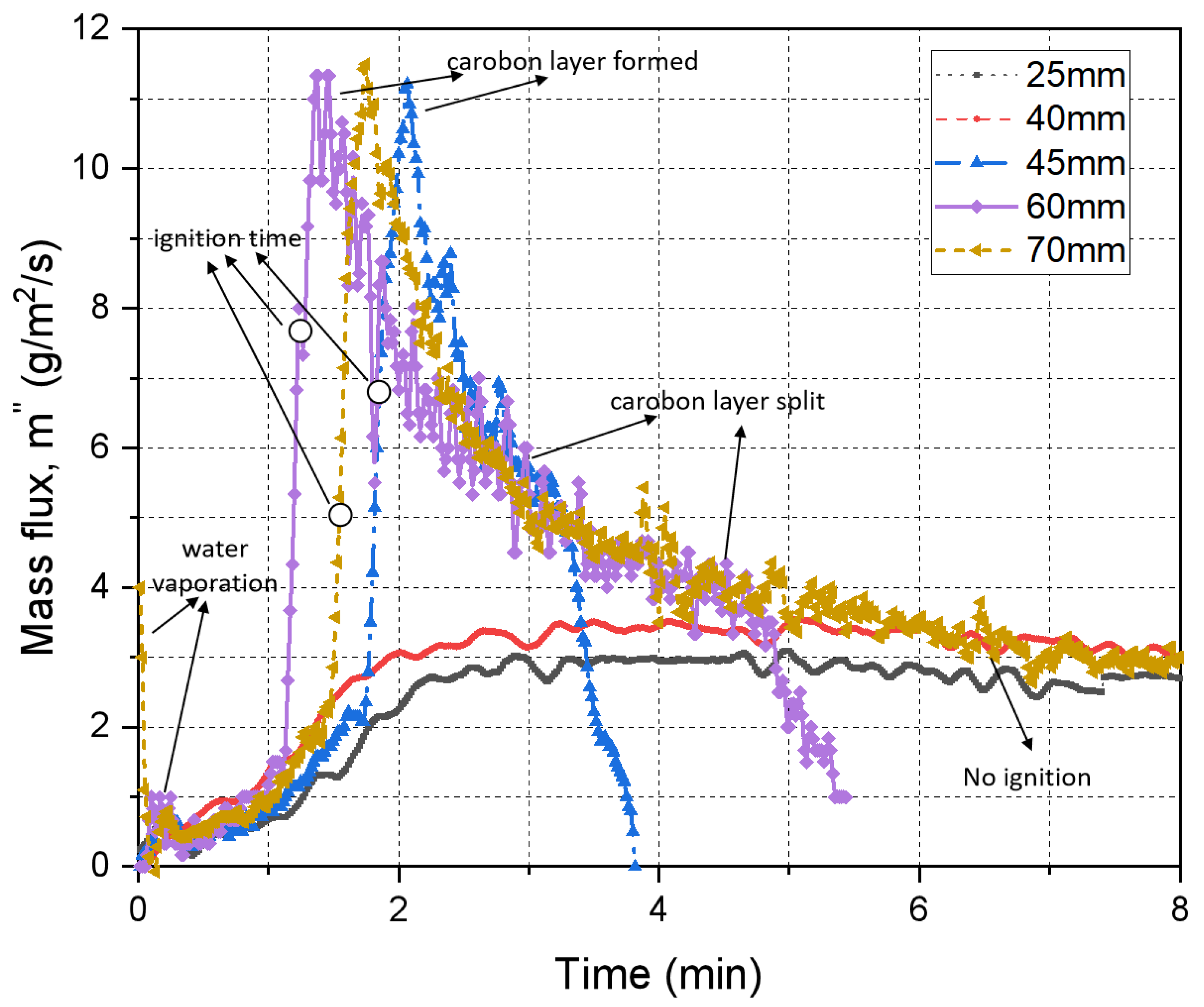
Figure 7 is the comparison of the MLR of pine wood at different radiant distances under low heat flow (25 kw/m2). When D < 40 mm, pine wood cannot be ignited. The rise in the mass flux curve is mainly due to the evaporation of water. When 45 mm ≤ D ≤ 60 mm, the curves trend are similar. There are three peak in the curves. When D = 45 mm, under the action of the applied radiant heat flow, the outer layer of moisture evaporated and MLR reaches the first peak. Then, volatilization occurs on the pine wood and the MLR curve increases sharply. Autoignition occurs during the rising period of the MLR curve. This process lasts about 108 s. After the flaming combustion, the mass loss flux of the pine wood increased. Due to the combustion of volatile compounds and the effect of thermal feedback, the mass loss flux of the wood quickly reached a peak of 11 g/m2/s. At this time, the outer layer of the wood formed a certain thickness of the carbon layer, which prevented the rapid transfer of heat to the interior of the wood, and the temperature rise in the inner layer began to slow down, and the mass loss flux also began to drop sharply. Until about 150 s, the carbon on the outer layer of wood slowly split, heat began to pass through the carbon layer into the inner layer of the wood block, making the decline in mass loss flux slow, and the second peak of mass loss flux appeared at about 190 s. As the bottom temperature slowly approaches the surface temperature, the mass loss flux approaches 0 at the end of the pyrolysis and combustion process of wood. Compare the purple curve and blue curve: the purple curve hits the first peak faster than the blue curve, but the peak value is the same, which means the radiant distance D has an influence on the pyrolysis process of wood. The ignition is close to the pyrolysis peak, and the heating effect is weakened. The second peak of the blue curve is reached earlier than the yellow curve. The value of the blue curve (5 g/m2/s) is higher than the value of the yellow curve (4 g/m2/s).
3.1.4. Fuel Type Influence
Figure 8 shows the comparison of the mass loss fluxes of the different types of fuel at the same distance, D = 60 mm. When D = 60 mm, the ignition mechanism of PMMA, pine needle and pine wood is the same. They are all heater ignition. From the figure, it can be seen that there are significant differences in the mass loss processes of different types of fuels due to different thermal conductivities and densities. The rate of elevation of mass loss flux is significantly fastest for pine needles, followed by pine wood and, finally, PMMA. This is because the thermal conductivity and density of these three fuels are ranked as PMMA > pine wood > pine needle. Therefore, the surface temperature of pine needle increases at the fastest rate among the three fuels, making the pyrolysis and combustion process of pine needle faster.
By comparing the time of the flaming ignition delay, we can see that the fuel type has a great influence on the ignition delay time of the fuel. When D = 60 mm, pine needle has the shortest ignition delay time due to it having the smallest density and lowest thermal conductivity, while PMMA has the longest ignition delay time due to it having the largest density and highest thermal conductivity.
4. Discussion
4.1. The Ignition Limit of Flaming
As 3–5 repeats were performed for any given experimental condition, the ignition probability (Pig) is defined as the ratio of the ignition times (Nig) to number of total repeating runs (Ntot). Thus, Pig = Nig/Ntot. Accordingly, a transition ignition region can be quantified between Pig = 5% and 95% [37]. Here, we define the particle condition at Pig = 50% as the ignition limit [37].
The ignition delay time, tig of sustained flaming was defined as the interval between the acing of thermal radiation (t = 0) and the appearance of the sustainable flame [37,38]. Two different flaming ignition times were found for direct flaming ignition and smoldering-to-flaming transition ignition. From the above analysis of the experimental phenomena, we can conclude that the distance of the fuel bed from the cone heater and the characteristics of the fuel have effects on the ignition delay time of the fuel.
By plotting the ignition time under different radiant distances (D), the propensity for the flaming ignition of the PMMA, pine needle and pine wood can be quantified. Figure 9 shows the ignition delay time of different type of fuels at different radiant distances, D. The error bars show the standard deviations of the values measured from all repeating tests. The ignition delay time decreases as radiant distant increases; firstly, it reaches the minimum value and then increases as the radiant distance increases, which has ever appeared in previous work. More importantly, by decreasing the radiant distance and ignition time, the observed phenomena in the current non-piloted ignition study can be categorized into two regions: (1) flaming autoignition and (2) no ignition. For comparison, a much larger radiant distance (a much higher temperature of heat source) is required to initiate the flaming ignition of PMMA than that of pine wood and than that of pine needle (48 mm vs. 40 mm vs. 35 mm).
Overall, the materials follow a similar trend. There is an approximate hyperbolic relationship between ignition delay time, tig and radiant distance, D, similar to previous work [10]. One marked difference between materials was the range of the ignition delay times. PMMA had a relatively large range of ignition delay time. The ignition delay time of pine needles was between 50 s and 200 s. In the case of pine wood, the range of ignition delay time is so narrow. At the same time, it is also observed that all materials have a critical position of minimum ignition delay time. It can be seen from the experimental results that this position is 60 mm away from the cone heater.
4.2. Radiant Distance Effect on the Flaming Ignition Behaviors
Figure 10, left plots the flaming ignition delay time of PMMA, pine wood and pine needle with different radiant distances. It can be found that the flaming ignition delay time is sensitive to the radiant distance. The experimental results are replotted as against distance, D, in Figure 10, right. This kind of plot has been commonly used for the influence of heat flux on the ignition delay time for both pilot ignition [32] and autoignition [5].
For PMMA, when D < 60 mm, the slope of the experiment line is 0.0029. As D increases, the reaction delay decreases to yield short total ignition times. The gap is relatively small. When D > 60 mm, there is a nonlinear relationship between D and . As D increases, the reaction delay increases to yield long total ignition times. For pine wood, when D < 60 mm, the relationship of radiant distance and ignition delay time is linear. The slop of the experiment line is 0.0012. By comparison, for PMMA, the ignition delay time is more sensitive to the radiant distance, D.
For pine needle, there is a nonlinear relationship between flaming ignition delay time and radiant distance. According to the experimental phenomena and MLR curves, when D < 60 mm, there exist gas-phase flaming ignition, smoldering ignition and smoldering-to-flaming ignition, which are complex processes and have an influence on the ignition delay time. Smoldering ignition is a very slow process, and the MLR of smoldering is significantly lower than that of flaming ignition. The mechanism of smoldering autoignition and smoldering-to-flaming autoignition will be conducted in the future.
5. Conclusions
The autoignition of PMMA, pine needle and pine wood were studied experimentally. The histories of MLR as well as ignition times were measured for various radiant distances. The following conclusions were reached:
- (1)
- The difference in autoignition behaviors at different radiant distances is explained by the coupled effect of the different gas-phase temperatures and the concentration dilution of the combustible pyrolysis volatiles.
- (2)
- The relationship between ignition delay time, tig and distance D is an approximate inverted U-shaped curve. One marked difference between materials was the range of ignition delay time. It is also observed that all materials have a critical position of ignition delay time, where the ignition delay time is shortest. It can be seen from the experimental results that this position is 60 mm away from the cone heater.
- (3)
- For experimental results of PMMA and pine wood, when D ≤ 60 mm, the relationship between and D is linear, and the predicted results are somewhat nonlinear. When D > 60 mm, there is nonlinear relationship between D and . This also provides a theoretical prediction of the critical radiant distance.
Funding
The Fundamental Research Funds for the Central Universities (WK2040000024).
Institutional Review Board Statement
Not applicable.
Informed Consent Statement
Not applicable.
Data Availability Statement
The authors declare that the data supporting the findings of this study are available within the article.
Conflicts of Interest
The authors declare that they have no known competing financial interests or personal relationships that could have appeared to influence the work reported in this paper.
References
- Mell, W.E.; Manzello, S.L.; Maranghides, A.; Butry, D.; Rehm, R.G. The wildland–urban interface fire problem–current approaches and research needs. Int. J. Wildland Fire 2010, 19, 238–251. [Google Scholar] [CrossRef]
- Cohen, J.D. What is the Wildland Fire Threat to Homes? School of Forestry, Northern Arizona University: Flagstaff, AZ, USA, 2000. [Google Scholar]
- Kashiwagi, T. Experimental observation of radiative ignition mechanisms. Combust. Flame 1979, 34, 231–244. [Google Scholar] [CrossRef]
- Simms, D.L.; Law, M. The ignition of wet and dry wood by radiation. Combust. Flame 1967, 11, 377–388. [Google Scholar] [CrossRef]
- Tsai, T.H.; Li, M.J.; Shih, I.Y.; Jih, R.; Wong, S.C. Experimental and numerical study of autoignition and pilot ignition of PMMA plates in a cone calorimeter. Combust. Flame 2001, 124, 466–480. [Google Scholar] [CrossRef]
- Boonmee, N.; Quintiere, J.G. Glowing and flaming autoignition of wood. Proc. Combust. Inst. 2002, 29, 289–296. [Google Scholar] [CrossRef]
- Shi, L.; Chew, M.Y.L. Experimental study of woods under external heat flux by autoignition. J. Therm. Anal. Calorim. 2013, 111, 1399–1407. [Google Scholar] [CrossRef]
- Shi, L.; Chew, M.Y.L. Fire behaviors of polymers under autoignition conditions in a cone calorimeter. Fire Saf. J. 2013, 61, 243–253. [Google Scholar] [CrossRef]
- Simeoni, A.; Thomas, J.C.; Bartoli, P.; Borowieck, P.; Reszka, P.; Colella, F.; Santoni, P.A.; Torero, J.L. Flammability studies for wildland and wildland–urban interface fires applied to pine needles and solid polymers. Fire Saf. J. 2012, 54, 203–217. [Google Scholar] [CrossRef]
- Yang, L.; Zhou, Y.; Wang, Y.; Dai, J.; Deng, Z.; Zhou, X. Autoignition of solid combustibles subjected to a uniform incident heat flux: The effect of distance from the radiation source. Combust. Flame 2011, 158, 1015–1017. [Google Scholar]
- McAllister, S.; Finney, M. Autoignition of wood under combined convective and radiative heating. Proc. Combust. Inst. 2017, 36, 3073–3080. [Google Scholar] [CrossRef]
- Tihay-Felicelli, V.; Santoni, P.A.; Barboni, T.; Leonelli, L. Autoignition of dead shrub twigs: Influence of diameter on ignition. Fire Technol. 2016, 52, 897–929. [Google Scholar] [CrossRef]
- Hadden, R.; Alkatib, A.; Rein, G.; Torero, J.L. Radiant Ignition of Polyurethane Foam: The Effect of Sample Size. Fire Technol. 2014, 50, 673–691. [Google Scholar] [CrossRef]
- Attia, N.F.; Goda, E.S.; Nour, M.A.; Sabaa, M.W.; Hassan, M.A. Novel synthesis of magnesium hydroxide nanoparticles modified with organic phosphate and their effect on the flammability of acrylonitrile-butadiene styrene nanocomposites. Mater. Chem. Phys. 2015, 168, 147–158. [Google Scholar] [CrossRef]
- Huang, G.; Chen, W.; Wu, T.; Guo, H.; Fu, C.; Xue, Y.; Wang, K.; Song, P. Multifunctional graphene-based nano-additives toward high-performance polymer nanocomposites with enhanced mechanical, thermal, flame retardancy and smoke suppressive properties. Chem. Eng. J. 2021, 410, 127590. [Google Scholar] [CrossRef]
- Fang, F.; Song, P.; Ran, S.; Guo, Z.; Wang, H.; Fang, Z. A facile way to prepare phosphorus-nitrogen-functionalized graphene oxide for enhancing the flame retardancy of epoxy resin. Compos. Commun. 2018, 10, 97–102. [Google Scholar] [CrossRef]
- Mindykowski, P.; Fuentes, A.; Consalvi, J.L.; Porterie, B. Piloted ignition of wildland fuels. Fire Saf. J. 2011, 46, 34–40. [Google Scholar] [CrossRef]
- McAllister, S.; Grenfell, I.; Hadlow, A.; Jolly, W.M.; Finney, M.; Cohen, J. Piloted ignition of live forest fuels. Fire Saf. J. 2011, 51, 133–142. [Google Scholar] [CrossRef]
- Porterie, B.; Nicolas, S.; Consalvi, J.L.; Loraud, J.C.; Giroud, F.; Picard, C. Modeling thermal impact of wildland fires on structures in the urban interface. Part 1: Radiative and convective components of flames representative of vegetation fires. Numer. Heat Tranf. A-Appl. 2005, 47, 471–489. [Google Scholar] [CrossRef]
- Consalvi, J.L.; Nmira, F.; Fuentes, A.; Mindykowski, P.; Porterie, B. Numerical study of piloted ignition of forest fuel layer. Proc. Combust. Inst. 2011, 33, 2641–2648. [Google Scholar] [CrossRef]
- Tao, J.; Wang, H. Energy uptake by wood during the ignition under external radiant heat flux. Appl. Therm. Eng. 2017, 124, 294–301. [Google Scholar] [CrossRef]
- Lamorlette, A. Analytical modeling of solid material ignition under a radiant heat flux coming from a spreading fire front. J. Therm. Sci. Eng. Appl. 2014, 6, 044501. [Google Scholar] [CrossRef]
- Vermesi, I.; DiDomizio, M.J.; Richter, F.; Weckman, E.J.; Rein, G. Pyrolysis and spontaneous ignition of wood under transient irradiation: Experiments and a-priori predictions. Fire Saf. J. 2017, 91, 218–225. [Google Scholar] [CrossRef]
- Cohen, J.D. Relating flame radiation to home ignition using modeling and experimental crown fires. Can. J. For. Res. 2004, 34, 1616–1626. [Google Scholar] [CrossRef]
- Reszka, P.; Borowiec, P.; Steinhaus, T.; Torero, J.L. A methodology for the estimation of ignition delay times in forest fire modelling. Combust. Flame 2012, 159, 3652–3657. [Google Scholar] [CrossRef]
- Zárate, L.; Arnaldos, J.; Casal, J. Establishing safety distances for wildland fires. Fire Saf. J. 2008, 43, 565–575. [Google Scholar] [CrossRef]
- Rossi, J.L.; Simeoni, A.; Moretti, B.; Leroy-Cancellieri, V. An analytical model based on radiative heating for the determination of safety distances for wildland fires. Fire Saf. J. 2011, 46, 520–527. [Google Scholar] [CrossRef]
- Billaud, Y.; Kaiss, A.; Consalvi, J.L.; Porterie, B. Monte Carlo estimation of thermal radiation from wildland fires. Int. J. Therm. Sci. 2011, 50, 2–11. [Google Scholar] [CrossRef]
- Wang, S.; Huang, X.; Chen, H.; Liu, N. Interaction between flaming and smouldering in hot-particle ignition of forest fuels and effects of moisture and wind. Int. J. Wildland Fire 2016, 26, 71–81. [Google Scholar] [CrossRef]
- Luche, J.; Rogaume, T.; Richard, F.; Guillaume, E. Characterization of thermal properties and analysis of combustion behavior of PMMA in a cone calorimeter. Fire Saf. J. 2011, 46, 451–461. [Google Scholar] [CrossRef]
- Rhodes, B.T.; Quintiere, J.G. Burning rate and flame heat flux for PMMA in a cone calorimeter. Fire Saf. J. 1996, 26, 221–240. [Google Scholar] [CrossRef]
- Gong, J.; Zhu, Z.; Zhang, M.; Zhai, C.; Wang, X. Piloted ignition of vertical polymethyl methacrylate (PMMA) exposed to power-law increasing radiation. Appl. Therm. Eng. 2022, 217, 118996. [Google Scholar] [CrossRef]
- Pandey, P.; Anbudayanidhi, S.; Mohanty, S.; Nayak, S.K. Flammability and thermal characterization of PMMA/clay nanocomposites and thermal kinetics analysis. Polym. Compos. 2012, 33, 2058–2071. [Google Scholar] [CrossRef]
- Gong, J.; Zhai, C.; Yang, L.; Wang, Z. Ignition of polymers under exponential heat flux considering both surface and in-depth absorptions. Int. J. Therm. Sci. 2020, 151, 106242. [Google Scholar] [CrossRef]
- Chen, T.B.Y.; Yuen, A.C.Y.; Wang, C.; Yeoh, G.H.; Timchenko, V.; Cheung, S.C.; Chan, Q.N.; Yang, W. Predicting the fire spread rate of a sloped pine needle board utilizing pyrolysis modelling with detailed gas-phase combustion. Int. J. Heat Mass Transf. 2018, 125, 310–322. [Google Scholar] [CrossRef]
- Lin, B.X.; Wu, Y.; Xu, M.X.; Chen, Z.G. Experimental investigation on spark ignition and flame propagation of swirling kerosene spray flames. Fuel 2021, 303, 121254. [Google Scholar] [CrossRef]
- Fang, W.; Peng, Z.; Chen, H. Ignition of pine needle fuel bed by the coupled effects of a hot metal particle and thermal radiation. Proc. Combust. Inst. 2021, 38, 5101–5108. [Google Scholar] [CrossRef]
- Thomas, J.C.; Simeoni, A.; Gallagher, M.; Skowronski, N. An experimental study evaluating the burning dynamics of pitch pine needle beds using the FPA. Fire Saf. Sci. 2014, 11, 1406–1419. [Google Scholar] [CrossRef]
Figure 1.
Schematic of experimental setup.

Figure 2.
Timelapse images of flaming ignition of the PMMA (D = 50 mm).

Figure 3.
Time evolution of mass-flux difference in the ignition process of PMMA with different distances, D.
Figure 3.
Time evolution of mass-flux difference in the ignition process of PMMA with different distances, D.

Figure 4.
Timelapse images of ignition phenomena of pine needle: (a) D = 45 mm; (b) D = 50 mm; (c) D = 60 mm.
Figure 4.
Timelapse images of ignition phenomena of pine needle: (a) D = 45 mm; (b) D = 50 mm; (c) D = 60 mm.

Figure 5.
Time evolution of mass-flux difference in the ignition process of pine needle with different distances, D.
Figure 5.
Time evolution of mass-flux difference in the ignition process of pine needle with different distances, D.

Figure 6.
Timelapse images of ignition phenomena of pine wood: (a) D = 45 mm; (b) D = 80 mm.

Figure 7.
Time evolution of mass flux difference in the ignition process of pine wood with different distances, D.
Figure 7.
Time evolution of mass flux difference in the ignition process of pine wood with different distances, D.

Figure 8.
Time evolution of mass flux difference in the ignition process of different fuel types.

Figure 9.
The ignition delay time of different types of fuels.

Figure 10.
Theoretical and experimental ignition times for autoignition, (left) tig against D; (right) against D of different types of fuel: (a) PMMA, (b) pine wood, and (c) pine needle.
Figure 10.
Theoretical and experimental ignition times for autoignition, (left) tig against D; (right) against D of different types of fuel: (a) PMMA, (b) pine wood, and (c) pine needle.


Table 1.
Experimental conditions.
| Type of Heat | Radiation Heat Flux /(kW/m2) | Distance from Heater to Fuel (mm) | Surface Temperature of Cone Center (°C) | Type of Fuel Bed | Density of Fuel Bed (kg/m3) |
|---|---|---|---|---|---|
| Radiation | 25 | 25, 40, 45, 50, 55, 60, 70, 80 | 433, 452, 470, 505, 524, 585, 633 | Pine needle | 46 |
| Pine wood | 359.2 | ||||
| PMM | 1190 |
Disclaimer/Publisher’s Note: The statements, opinions and data contained in all publications are solely those of the individual author(s) and contributor(s) and not of MDPI and/or the editor(s). MDPI and/or the editor(s) disclaim responsibility for any injury to people or property resulting from any ideas, methods, instructions or products referred to in the content. |
© 2023 by the author. Licensee MDPI, Basel, Switzerland. This article is an open access article distributed under the terms and conditions of the Creative Commons Attribution (CC BY) license (https://creativecommons.org/licenses/by/4.0/).
Share and Cite
MDPI and ACS Style
Song, J. Flaming Ignition of PMMA, Pine Wood and Pine Needle by External Radiation: Autoignition and Radiant Distance Effect. Fire 2023, 6, 163. https://doi.org/10.3390/fire6040163
AMA Style
Song J. Flaming Ignition of PMMA, Pine Wood and Pine Needle by External Radiation: Autoignition and Radiant Distance Effect. Fire. 2023; 6(4):163. https://doi.org/10.3390/fire6040163
Chicago/Turabian StyleSong, Jiayun. 2023. "Flaming Ignition of PMMA, Pine Wood and Pine Needle by External Radiation: Autoignition and Radiant Distance Effect" Fire 6, no. 4: 163. https://doi.org/10.3390/fire6040163