
Modeling of Hydrogen Dispersion, Jet Fires and Explosions Caused by Hydrogen Pipeline Leakage
by
 ,
,
Yujie Lin
1,2,3,
Xiaodong Ling
1,2,4,
Anfeng Yu
1,2,3,4,*,
Yi Liu
1,2,3,
Di Liu
1,2,4,
Yazhen Wang
1,2,4,
Qian Wu
1,2,3 and
Yuan Lu
5 1
State Key Laboratory of Chemical Safety, Qingdao 266071, China
2
SINOPEC Research Institute of Safety Engineering Co., Ltd., Qingdao 266071, China
3
National Registration Center for Chemicals, Ministry of Emergency Management, Qingdao 266071, China
4
SINOPEC National Petrochemical Project Risk Assessment Technical Center Co., Ltd., Qingdao 266071, China
5
School of Safety Engineering, Changzhou University, Changzhou 213164, China
*
Author to whom correspondence should be addressed.
Fire 2024, 7(1), 8; https://doi.org/10.3390/fire7010008
Submission received: 2 November 2023
/
Revised: 6 December 2023
/
Accepted: 14 December 2023
/
Published: 23 December 2023
(This article belongs to the Special Issue Flame Radiation)
Abstract
:Accidental hydrogen releases from pipelines pose significant risks, particularly with the expanding deployment of hydrogen infrastructure. Despite this, there has been a lack of thorough investigation into hydrogen leakage from pipelines, especially under complex real-world conditions. This study addresses this gap by modeling hydrogen gas dispersion, jet fires, and explosions based on practical scenarios. Various factors influencing accident consequences, such as leak hole size, wind speed, wind direction, and trench presence, were systematically examined. The findings reveal that both hydrogen dispersion distance and jet flame thermal radiation distance increase with leak hole size and wind speed. Specifically, the longest dispersion and radiation distances occur when the wind direction aligns with the trench, which is 110 m where the hydrogen concentration is 4% and 76 m where the radiation is 15.8 kW/m2 in the case of a 325 mm leak hole and wind under 10 m/s. Meanwhile, pipelines lacking trenching exhibit the shortest distances, 0.17 m and 0.98 m, at a hydrogen concentration of 4% and 15.8 kW/m2 radiation with a leak hole size of 3.25 mm and no wind. Moreover, under relatively higher wind speeds, hydrogen concentration stratification occurs. Notably, the low congestion surrounding the pipeline results in an explosion overpressure too low to cause damage; namely, the highest overpressure is 8 kPa but this lasts less than 0.2 s. This comprehensive numerical study of hydrogen pipeline leakage offers valuable quantitative insights, serving as a vital reference for facility siting and design considerations to eliminate the risk of fire incidents.
1. Introduction
Hydrogen stands out as a clean and renewable resource crucial in the fight against global warming. Hydrogen pipelines serve as a vital component in the industrial chain, offering a cost-effective means of hydrogen transmission [1]. Numerous hydrogen pipelines have been established worldwide, particularly in Europe, America, Asia, and even in China, where pipelines like Jinling–Yangtze, Baling–Changling, and Jiyu-an–Luoyang have been constructed. However, the low density and low ignition energy of hydrogen make leaks from pipelines potentially hazardous, leading to risks including gas dispersion, jet fires, and explosions [2]. Moreover, complicated boundary conditions include variables like wind speed and wind direction, particularly in cases of elevated and buried pipelines, which escalate the risks.
Considerable research efforts have been dedicated to pipeline safety, with a primary focus on hydrogen refueling stations/plants and hydrogen-fuel-cell vehicles. For instance, Gao et al. studied hydrogen dispersion, jet fires, and explosions in a nuclear hydrogen production system [3]. Liang et al. simulated leakage and explosion in renewable hydrogen refueling stations [4]. Some models have been developed for high-pressure hydrogen leakage consequences. For high-pressure hydrogen leakage, Birch et al. introduced a notional nozzle model for hydrogen leakage and dispersion, assuming hydrogen leaking from a virtual nozzle with characteristics mirroring those of a real nozzle [5,6,7]. Wang et al. proposed a simplified model using the specific heat capacity of hydrogen to calculate jet velocity and jet density based on the notional model [8]. Makarov et al. created models predicting unignited releases and pressure peaking phenomena in still air [9]. In the realm of jet fires, Ekoto et al. developed a numerical model for large-scale hydrogen jet fire radiation [10]. Houf proposed models for visible hydrogen jet fires mainly based on the flame’s Froude number [11]. Zhou et al. proposed a theoretical model for hydrogen flame length and heat flux [12]. Regarding hydrogen explosion, the TNO model, BST model, and TNT equivalent model have been applied [13]. Lowesmith et al. conducted a series of large-scale methane/hydrogen mixture explosion experiments, and a modified version of the Shell Global Solutions model was used to describe overpressure, agreeing well with experimental results [14]. Some works have been conducted on the hydrogen pipeline risk assessment method, but no quantitative results were revealed [2]. In addition, case studies of hydrogen pipelines have been conducted. For dispersion, Wilkening conducted computational fluid dynamics (CFD) simulations to analyze hydrogen leakage and dispersion processes under varying wind conditions [6]. For jet fires, Froeling et al. investigated hydrogen jet fire events for hydrogen transported in natural gas transmission pipelines and proposed comprehensive mathematical transformations of the geometric view factor [15]. Other works used the CFD method or PHAST to study fire length, radiation, and fire damage [16,17,18]. Lowesmith conducted large-scale experiments, finding that, compared to natural gas pipelines, pipelines conveying a natural gas/hydrogen mixture presented a slightly lower hazard in terms of thermal dose [19,20]. For explosions, Russo used the TNO model to assess hydrogen pipeline explosion damage to people and buildings [21]. Groethe et al. conducted large-scale deflagration and detonation experiments on hydrogen and air mixtures, helping to validate numerical models [22]. CFD methods, such as FLACS, have been used to simulate vented hydrogen deflagrations [23]. We can conclude that most studies only focused on one or two consequences; no work has been carried out on dispersion, jet fires, and explosions due to hydrogen pipeline leakage.
Furthermore, in practical cases, the impact of complex boundary conditions, such as wind speed and wind direction, on the evolution of gas dispersion, jet fires, and explosions varies between elevated pipelines and buried pipelines. Leak hole size, wind speed, and wind direction play crucial roles in gas leakage and dispersion, significantly influencing incidents. This behavior is notably more intricate and needs to be explored. Hence, it is imperative to conduct a comprehensive modeling study concerning the consequences of hydrogen pipeline leakage, taking into account both elevated and buried pipelines.
In this study, the effects of leak hole size and various boundary conditions, including wind speed, wind direction, and the presence of a trench, on hydrogen gas dispersion, jet fires, and explosions were systematically investigated based on practical cases. A total of 180 cases were studied using computational fluid dynamics (CFD) simulations. The novelty of this work lies in uncovering the influences of leak hole size and boundary conditions, such as wind speed, wind direction, and the presence of a trench, on the hazardous consequences of hydrogen pipeline leaks. Additionally, the dispersion distance and jet flame thermal radiation distance for different scenarios were determined, providing essential insights into hydrogen pipeline facility siting and risk assessment.
2. Numerical Approach
In this study, we employed a computational fluid dynamics (CFD) method, FLACS, to investigate three significant outcomes, which were hydrogen gas dispersion, jet fires, and explosions resulting from accidental releases from hydrogen pipelines. Jet discharge and expansion were simulated using a widely employed pseudo-source model known as the notional-nozzle model, which has been extensively used for modeling hydrocarbon and hydrogen discharges under high-pressure conditions [5,6,7]. This model assumes no mixing of hydrogen with air during the jet expansion, resulting in the determination of the expanded jet (with a leak hole size typically 2–20 times larger than the discharge hole size, depending on the discharge pressure) as the pseudo-source in the simulation. The k-ε model was employed to capture turbulence effects.
For hydrogen combustion modeling, the EDC model assuming an infinite chemical reaction rate was used and the radiation calculation used the discrete transfer radiation (DTM) model [24]. Explosion overpressure was simulated using the Euler model. It is essential to note that FLACS has been validated in real cases including leakage, dispersion, hydrogen jet fires, and hydrogen explosions in previous studies [23,24,25].
2.1. 3-D Models and Boundary Conditions
Figure 1 illustrates the 3D model of a hydrogen pipeline, based on an actual hydrogen pipeline in China, featuring an inner diameter of 325 mm and operating at an absolute pressure of 40 bar; the concentration of the flowing hydrogen is 99.99% and the operation temperature is 323 K. To account for typical operational scenarios, two models were established: one representing leakages in an unconfined open space for elevated pipelines, and the other simulating releases in a trench for pipelines buried or surrounded by obstacles. The trench needs to be considered because when the high-pressure hydrogen pipeline leaks, the momentum of leaking hydrogen impinges on nearby obstacles, forming a trench. It is worth noting that, in assessing the risk of buried pipeline leakages, some studies disregarded the impact of soil on the jet’s momentum, while others incorporated a trench experiment considering the substantial momentum of hydrogen leakage jets [18]. For buried pipelines, a trench with the dimensions of 2.5 m width, 5 m length, and 2 m depth was assumed. Five leak hole sizes were designed, representing 0.01%, 0.1%, 1%, 10%, and 100% leakage areas relative to the pipeline’s cross-sectional area, translating to leak hole sizes of 3.3 mm, 10.3 mm, 32.5 mm, 102.8 mm, and 325 mm. These sizes encompass typical leakages, ranging from pinholes to pipeline ruptures, as defined by the European Gas Pipeline Incident Data Group [26]. To evaluate wind interaction with the trench, two wind directions—parallel and perpendicular to the trench—were considered. The leak direction was set to be vertical considering that the high momentum of hydrogen forms a crater in ground and then the jet is redirected to a vertical direction [27]. The analysis incorporated four typical wind speeds: 0 m/s, 2 m/s, 6 m/s, and 10 m/s, noting that the annual average wind speed is 6 m/s.
2.2. Grid Sensitivity Study and Steady Conditions
Hydrogen gas dispersion was studied using grid sizes of 0.3 m, 0.5 m, and 1 m, with grids stretched towards the far field and refined around the leak hole. Figure 2 illustrates that a grid size of 1 m results in notably shorter dispersion distances compared to 0.5 m and 0.3 m, whereas the outcomes for 0.5 m and 0.3 m grid sizes are very similar. Hence, 0.5 m was chosen as the optimal grid size, balancing accuracy and efficiency. Noting that the main domain of all cases is 300 m 300 m 300 m, the computational grid was set as 0.5 m 0.5 m 0.5 m. For the domain around the leak hole, FLACS automatically generates finer grids and smooths the gap between the finer grids and the set grids (0.5 m 0.5 m). The finer grids are small enough to simulate the smallest leak hole (3.25 mm).
Typical hydrogen gas dispersion plumes are depicted in Figure 3. Red circles and arrows in Figure 3 show that the gas concentrations of hydrogen jets reached steady states within 14 s. Red lines in Figure 3 show that the lengths of the hydrogen jets reached stable states in 14 s as well. In this study, gas concentrations were calculated by averaging over these steady-state durations. For jet flames, characteristics such as far field radiation and temperature were stabilized within 4 s and time-averaged values after stabilization were used in further analysis. Given the swift evolution of explosions, overpressures were monitored every 0.01 s for analysis.
3. Results and Discussion
3.1. Hydrogen Gas Dispersion
For hydrogen gas dispersion, it is crucial to consider its flammability limits, which range from 4% to 75.6% mole fraction, indicating the conditions under which it can lead to jet fires or explosions under ambient conditions. Note that, as shown in Figure 4, the dispersion distances L and the radiation distances Lr for different leak hole sizes are essentially different, illustrating that the present computational grids are capable of simulating leak hole sizes of 3.25–325 mm. In open spaces, significant hydrogen clouds above 75.6% (the upper flammability limit, UFL) are less likely to form. Consequently, in this study, the dispersion distance is defined as the horizontal distance from the leak hole to the point where the hydrogen concentration reaches 4% (lower flammability limit). Figure 4 compares dispersion distances (L) in unconfined open spaces and those with a trench (under two different wind directions); the key findings are:
- L increases significantly with leak hole size (d) due to the higher mass flow rates associated with larger leak holes.
- L moderately increases with wind speed (Uw). Higher wind speeds help gas cloud dilution but also bend the hydrogen plume toward the ground, increasing horizontal dispersion. Notably, when d = 3.3 mm and Uw = 0 m/s, L is the shortest at 0.17 m, equivalent to the hydrogen plume radius. The most hazardous scenario occurs at d = 325 mm and Uw = 10 m/s, resulting in the longest L at 110 m, serving as a conservative reference for hydrogen pipeline design.
- Under the same wind speed, L is the longest when the wind blows towards the longer side of the trench and is the shortest in unconfined cases. In trench scenarios, wind blowing towards the longer side results in a longer wind effect length, reducing wind dilution. Defining L as the ratio of the longest L and the shortest L of the same leak hole size under the same wind speed, the average value for L is 1.1, offering a valuable safety design reference. Notably, these ratios vary with the trench shape, a topic deserving future research.
- At relatively high wind speeds (6 m/s, 10 m/s), hydrogen attaches to the ground, causing concentration stratifications. The red circles in Figure 5 denote hydrogen concentration stratification. The Conada effect and fluid viscosity lead to ground attachment, particularly evident at high wind speeds, which enhance the Conada effect. This stratification poses safety risks due to potential ground-level ignition sources, including friction-induced static electricity and the tendency for flames to develop along the ground post-ignition. This phenomenon necessitates comprehensive exploration in future hydrogen pipeline leakage studies.
3.2. Jet Fire
Jet fires occur when the hydrogen is ignited immediately after the leakage. In Figure 6, the radiation contours of hydrogen jet fires are depicted. The illustration reveals that as wind speed (Uw) increases, the inertial force of the wind (, where represents the density of ambient air) makes the flame bend towards the ground [28]. Consequently, with higher wind speeds, the flame centerline deviates further from the vertical direction. Note that no large-scale vertical hydrogen jet flame under the influence of wind has been reported. However, wind has been considered as an essential factor in many works [13]. The interaction of wind and jet flames is mainly the interaction of the inertial forces brought by the wind and the momentum of high-pressure hydrogen leakage. The inertial force brought by the wind, , can be calculated as [28], where is the area of fire facing the wind, is the ambient density, and is the wind speed. Further simplifying, the vertical jet fire can be understood as two isosceles triangles with the same base. The flame length and flame width can be calculated following previous work [11]. is calculated as 123,311.1 under a wind speed of 10 m/s. The momentum of high-pressure hydrogen leakage () is calculated as , where is the density of jet flow at the leak hole exit, is the gas release rate at the leak hole exit, and d is the leak area. In addition, and can be calculated following Wang’s work based on the notional nozzle model [8]. Therefore, is calculated as 1.89 kg/m3, is calculated as 1158.48 m/s, and M is calculated as 210,243.6 when the leak hole size is 325 mm. The inertial force of wind is unneglectable compared with the momentum of high-pressure hydrogen leakage, which demonstrates that a wind speed of 10 m/s could have an impact on the hydrogen flame. Note that and are calculated with simplified models only to show the influence of wind on the hydrogen flame.
Radiation serves as a fundamental thermal parameter in jet fires and is commonly utilized as a safety assessment criterion. In this study, the discrete transfer radiation (DTM) model was employed for radiation simulation. This model solves radiation distribution within three-dimensional complex geometries by calculating the rays emitted from boundaries and solids within the domain [24]. To trace the rays before they strike a solid surface in each direction within the radiation space, Equation (1) is proposed. Here, represents ray intensity at the entry of the control volume, represents ray intensity at the exit of the control volume, is the extinction coefficient, and S is the source function. It is worth noting that and S remain constant within the interval .
For a finite solid angle , the incident radiative heat flux and emitted flux can be obtained by Equations (2) and (3), where is emissivity and is absorption efficiency, is the polar angle, and is the azimuthal angle. Thus, the net surface heat flux is shown in Equation (4).
For a finite solid angle , the incident radiative heat flux and emitted flux can be determined using Equations (2) and (3), where represents emissivity, is the absorption efficiency, is the polar angle, and is the azimuthal angle. Consequently, the net surface heat flux is expressed as shown in Equation (4).
Furthermore, the energy of a ray passing through a volume n is given by Equation (5), where An represents the area of the surface element from which the ray is emitted.
The divergence of radiative heat flux is calculated by adding the energy source divided by volume, Vn, as in Equation (6). Then, the source function in Equation (1) is obtained with Equation (7) for the isotopically scattering medium, where IB is the black body intensity and is albedo. In addition, the finite solid angle is calculated by angular subdivision as in Equation (8).
The divergence of radiative heat flux is computed by adding the energy source divided by the volume Vn, as shown in Equation (6). Subsequently, the source function in Equation (1) is determined as presented in Equation (7) for an isotopically scattering medium, where IB represents the black body intensity and is the albedo. Additionally, the finite solid angle is calculated through angular subdivision, as described in Equation (8).
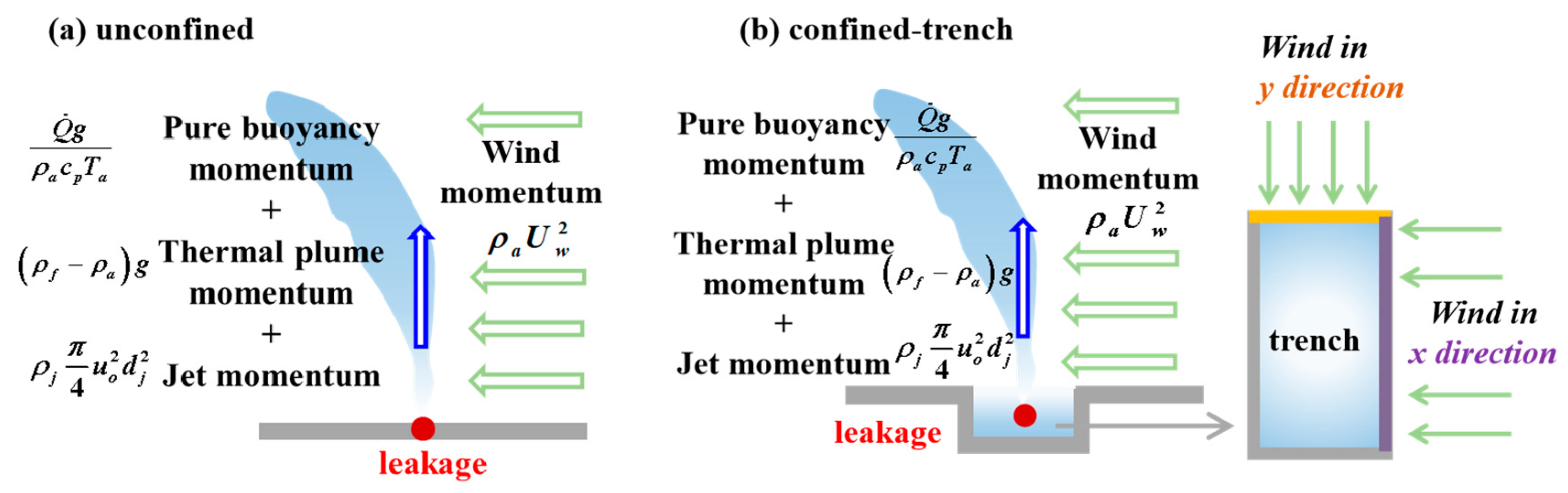
Table 1 outlines various radiation heat flux () criteria for analyzing the thermal behavior of jet fires. Figure 6 displays the radiation heat flux for different leak hole sizes, wind speeds, wind directions, and confined/unconfined spaces as calculated by the DTM model. An illustration of the influential factors on jet fires is presented in Figure 7. The main findings are as follows:
- An increase in leak hole size leads to a greater jet flame thermal radiation distance (Lr). This is attributed to higher mass burning rates for hydrogen, as well as increased jet momentum and pure plume momentum under the assumption of stoichiometric combustion.
- Higher wind speeds result in an increase in Lr. Figure 7 illustrates four types of momentum contributing to the thermal plume: pure buoyancy momentum from the hydrogen plume (, where is the heat release rate (kW), is gravitational acceleration (m/s2), is the ambient density (kg/m3), is the specific heat of air at constant pressure (kJkg−1K−1), and is the ambient temperature (K)), thermal plume momentum from jet fire combustion (, where is the flame density (kg/m3)), jet momentum due to high-pressure leaks (, where is hydrogen density at the leak hole exit (kg/m3), is the hydrogen flow velocity at the leak hole exit (m/s), and is the leak hole diameter (m)), and wind momentum proportional to wind speed [28]. Winds not only bring hydrogen downward but also intensify turbulence and combustion. Higher wind momentum drives the thermal plume in the downwind direction, enhancing combustion and leading to an increase in Lr. For instance, when d = 325 mm, Uw = 10 m/s, and wind blows along the x-direction, Lr is the longest. Conversely, for d = 3.3 mm and Uw =0 m/s in an unconfined open space, Lr is the smallest. The radiation criterion of 15.8 kW/m2 is widely used to denote radiation hazard as the threshold causing 1% fatality and doing no harm to buildings [27]. In present cases, the greatest distance where radiation is 15.8 kW/m2 is 76 m, offering valuable guidelines for safety design.
- In confined trench spaces, Lr is greater when winds blow along the x-direction compared to the y-direction as a result of a larger area being directly influenced by the wind. Overall, for the same leak hole size and wind speed, Lr in unconfined open space is smaller than Lr in confined trench spaces. It is important to note that hydrogen dispersion distribution, crucial in determining jet fire thermal behaviors, also factors into wind speed and direction. The largest ratio of Lr in a confined trench space with wind along the x-direction to Lr in an unconfined open space is 2, serving as a conservative reference for hydrogen pipeline design.
3.3. Explosion
Two critical values, 48.3 kPa and 17 kPa, are widely used as overpressure criteria to assess hydrogen explosions. Additionally, lethal distance/area, denoting the space between the leakage point and the area where pressure equals to 48.3 kPa (causing 100% mortality), is defined. Similarly, harmful distance/area, representing the space between the leakage point and the area where pressure equals 17 kPa (leading to 1% mortality), is established [3]. In this study, explosion simulations were carried out. Leakages with hole sizes of 3.3 mm and 10.3 mm did not result in explosions due to the limited volume of the hydrogen gas cloud and the low congestion.
For leak hole sizes of 32.5 mm, 102.8 mm, and 325 mm, larger leak hole sizes leading to larger-volume hydrogen gas clouds, explosions occurred. In these cases, owing to low congestion, the whole process of explosion lasted for 0.15 s, 0.16 s, and 0.19 s, respectively. During the process, overpressure first increased to the maximum value then decayed to the atmospheric pressure. The maximum overpressure in all cases was 8 kPa. Moreover, the impulse, which is the integral of the duration of the explosion and overpressure, is insufficient to cause damage owing to the low congestion around the hydrogen pipeline investigated in the present work.
Consequently, the likelihood of hydrogen pipeline explosions in low-congestion regions is minimal. It is worth noting that a previous study conducted hydrogen explosion experiments at refueling stations using plastic film enclosures. In empty spaces within the plastic film, the maximum measured overpressure was 7 kPa, which is too low to cause significant damage. This aligns with our findings, indicating that relatively spacious areas pose a low risk of explosion [3]. However, it is important to acknowledge that explosion hazards in hydrogen refueling stations with high congestion are significant due to the added congestion from facilities [3].
In summary, this study provides a comprehensive analysis of hydrogen leaks, considering gas dispersion, jet fires, and explosions, and quantitatively delineates the scope of potential hazards, shedding lights on consequence evolution under complex boundary conditions for hydrogen pipelines. These insights benefit the design and risk assessment of hydrogen pipeline systems.
4. Conclusions
This study investigated the consequences of hydrogen gas dispersion, jet fires, and explosions resulting from hydrogen pipeline leaks. Using practical case simulations with computational fluid dynamics (CFD), the study explored five leak hole sizes, four wind speeds, two wind directions, and both unconfined and confined trench spaces. The main findings are:
- Dispersion distances increase with leak hole size and wind speed. Moreover, the dispersion distance is greater under winds in the x-direction compared to the y-direction, and the dispersion distance in unconfined open spaces is the smallest. The maximum dispersion distance observed was 110 m. Additionally, hydrogen concentration stratifications occur under relatively high wind speeds due to the Conada effect.
- Jet flame thermal radiation distances, calculated using the DTM model, increase with leak hole size and wind speed. The radiation distance is the largest under winds in the x-direction and the smallest in unconfined open spaces. The longest radiation distance where the radiation is 15.8 kW/2 is 76 m.
- Explosion overpressures resulting from larger leak hole sizes in the present simulated pipelines are insufficient to cause damage. Leaks from smaller hole sizes, such as 10 mm or lower, pose minimal explosion hazards.
Author Contributions
Conceptualization, Y.L. (Yujie Lin) and X.L.; methodology, A.Y. and Y.L. (Yi Liu); software, Y.L. (Yujie Lin); validation, D.L. and Y.W.; analysis, Y.L. (Yujie Lin); investigation, Q.W.; resources, Q.W.; data curation, X.L.; writing—original draft preparation, Y.L. (Yujie Lin); writing—review and editing, Y.L. (Yuan Lu) and Y.L. (Yi Liu); visualization, Y.L. (Yujie Lin); supervision, A.Y.; project administration, A.Y.; funding acquisition, Y.L. (Yujie Lin) and X.L. All authors have read and agreed to the published version of the manuscript.
Funding
This research was funded jointly by the National Natural Science Foundation of China, grant numbers 52206190 and 52306171, and the Ministry of Science and Technology of China Petroleum and Chemical Corporation, grant number 122072.
Institutional Review Board Statement
Not applicable.
Informed Consent Statement
Not applicable.
Data Availability Statement
Research data can be provided upon request.
Acknowledgments
We are grateful to the National Natural Science Foundation of China and the Ministry of Science and Technology of China Petroleum and Chemical Corporation for providing findings.
Conflicts of Interest
There is no conflict of interest relevant to this article. Authors Yujie Lin, Xiaodong Ling, Anfeng Yu, Yi Liu, Di Liu, Yazhen Wang, Qian wu were employed by the company SINOPEC Research Institute of Safety Engineering Co., Ltd. and SINOPEC National Petrochemical Project Risk Assessment Technical Center Co., Ltd. The remaining authors declare that the research was conducted in the absence of any commercial or financial relationships that could be construed as a potential conflict of interest. The SINOPEC Research Institute of Safety Engineering Co., Ltd. and SINOPEC National Petrochemical Project Risk Assessment Technical Center Co., Ltd. had no role in the design of the study; in the collection, analyses, or interpretation of data; in the writing of the manuscript, or in the decision to publish the results.
References
- Studer, E.; Jamois, D.; Jallais, S.; Leroy, G.; Hebrard, J.; Blanchetière, V. Properties of large-scale methane/hydrogen jet fires. Int. J. Hydrogen Energy 2009, 34, 9611–9619. [Google Scholar] [CrossRef]
- Lins, P.; Almeida, A. Multidimensional risk analysis of hydrogen pipelines. Int. J. Hydrogen Energy 2012, 37, 13545–13554. [Google Scholar] [CrossRef]
- Gao, Q.; Wang, L.; Peng, W.; Zhang, P.; Chen, S. Safety analysis of leakage in a nuclear hydrogen production system. Int. J. Hydrogen Energy 2022, 47, 4916–4931. [Google Scholar] [CrossRef]
- Liang, Y.; Pan, X.; Zhang, C.; Xie, B.; Liu, S. The simulation and analysis of leakage and explosion at a renewable hydrogen refueling station. Int. J. Hydrogen Energy 2019, 44, 22608–22619. [Google Scholar] [CrossRef]
- Birch, D.; Brown, R.; Dodson, G.; Swaffield, F. The Structure and Concentration Decay of High Pressure Jets of Natural Gas. Combust. Sci. Technol. 1984, 36, 249–261. [Google Scholar] [CrossRef]
- Wilkening, H.; Baraldi, D. CFD modelling of accidental hydrogen release from pipelines. Int. J. Hydrogen Energy 2007, 32, 2206–2215. [Google Scholar] [CrossRef]
- Birch, D.; Hughes, J.; Swaffield, F. Velocity Decay of High Pressure Jets. Combust. Sci. Technol. 1987, 52, 161–171. [Google Scholar] [CrossRef]
- Yu, X.; Wu, Y.; Zhao, Y.; Wang, C. Flame characteristics of under-expanded, cryogenic hydrogen jet fire. Combust. Flame 2022, 244, 112294. [Google Scholar] [CrossRef]
- Makarov, D.; Shentsov, V.; Kuznetsov, M.; Molkov, V. Pressure peaking phenomenon: Model validation against unignited re-lease and jet fire experiments. Int. J. Hydrogen Energy 2018, 43, 9454–9469. [Google Scholar] [CrossRef]
- Ekoto, W.; Houf, G.; Ruggles, J.; Creitz, W.; Li, X. Large-Scale Hydrogen Jet Flame Radiant Fraction Measurements and Modeling. In Proceedings of the 9th International Pipeline Conference, Calgary, AB, Canada, 24–28 September 2012. [Google Scholar]
- Houf, W.; Schefer, R. Predicting radiative heat fluxes and flammability envelopes from unintended releases of hydrogen. Int. J. Hydrogen Energy 2007, 32, 136–151. [Google Scholar] [CrossRef]
- Zhou, K.; Wang, X.; Liu, M.; Liu, J. A theoretical framework for calculating full-scale jet fires induced by high-pressure hydro-gen/natural gas transient leakage. Int. J. Hydrogen Energy 2018, 43, 22765–22775. [Google Scholar] [CrossRef]
- Ehrhart, B.; Hecht, E. Hydrogen Plus Other Alternative Fuels Risk Assessment Models (HyRAM+) Version 4.1 Technical Reference Manual; Sandia National Lab. (SNL-NM): Albuquerque, NM, USA, 2022. [Google Scholar]
- Lowesmith, B.; Mumby, C.; Hankinson, G.; Puttock, J.S. Vented confined explosions involving methane/hydrogen mixtures. Int. J. Hydrogen Energy 2011, 36, 2337–2343. [Google Scholar] [CrossRef]
- Froeling, H.; Drge, M.T.; Nane, G.; Wijk, A. Quantitative risk analysis of a hazardous jet fire event for hydrogen transport in natural gas transmission pipelines. Int. J. Hydrogen Energy 2021, 46, 10411–10422. [Google Scholar] [CrossRef]
- Jang, C.; Choi, S.; Baek, J. CFD modeling and fire damage analysis of jet fire on hydrogen pipeline in a pipe rack structure. Int. J. Hydrogen Energy 2015, 40, 15760–15772. [Google Scholar] [CrossRef]
- Dagdougui, H.; Garbolino, E.; Paladino, O.; Sacile, R. Hazard and risk evaluation in hydrogen pipelines. Manag. Environ. Qual. 2011, 21, 712–725. [Google Scholar] [CrossRef]
- Lutostansky, E.; Creitz, L.; Jung, S.; Schork, J.; Worthington, D.; Xu, Y. Modeling of underground hydrogen pipelines. Process Saf. Prog. 2013, 32, 212–216. [Google Scholar] [CrossRef]
- Lowesmith, J.; Hankinson, G. Large scale experiments to study fires following the rupture of high pressure pipelines conveying natural gas and natural gas/hydrogen mixtures. Process Saf. Environ. 2013, 91, 101–111. [Google Scholar] [CrossRef]
- Lowesmith, J.; Hankinson, G. Large scale high pressure jet fires involving natural gas and natural gas/hydrogen mixtures. Process Saf. Environ. 2012, 90, 108–120. [Google Scholar] [CrossRef]
- Russo, P.; De Marco, A.; Parisi, F. Assessment of the Damage from Hydrogen Pipeline Explosions on People and Buildings. Energies 2020, 13, 5051. [Google Scholar] [CrossRef]
- Groethe, M.; Merilo, E.; Colton, J.; Chiba, S.; Sato, Y.; Iwabuchi, H. Large-scale hydrogen deflagrations and detonations. Int. J. Hydrogen Energy 2007, 32, 2125–2133. [Google Scholar] [CrossRef]
- Lucas, M.; Atanga, G.; Hisken, H.; Mauri, L.; Skjold, T. Simulating vented hydrogen deflagrations: Improved modelling in the CFD tool FLACS-hydrogen. Int. J. Hydrogen Energy 2021, 46, 12464–12473. [Google Scholar] [CrossRef]
- Gexon AS. Flacs CFD Manual. 2020. Available online: https://www.gexcon.com/support/flacs-cfd/technical-manuals/ (accessed on 1 January 2022).
- Dasgotra, A.; Varun Teja, G.V.V.; Sharma, A.; Mishra, K.B. CFD modeling of large-scale flammable cloud dispersion using FLACS. J. Loss Prev. Process Ind. 2018, 56, 531–536. [Google Scholar] [CrossRef]
- EGPID Group. Gas Pipeline Incidents: 11th Report of the European Gas Pipeline Incident Data Group. 2020. Available online: https://www.egig.eu/reports (accessed on 1 January 2022).
- Stephens, M.; Leewis, K.; Moore, D. A Model for Sizing High Consequence Areas Associated with Natural Gas Pipelines. In Proceedings of the 4th International Pipeline Conference, Calgary, AB, Canada, 29 September–3 October 2002. [Google Scholar]
- Lin, Y.; Zhang, X.; Hu, L. An experimental study and analysis on maximum horizontal extents of buoyant turbulent diffusion flames subject to relative strong cross flows. Fuel 2018, 234, 508–515. [Google Scholar] [CrossRef]
Figure 1.
3D model: (a) Aboveground pipeline; (b) buried pipeline.

Figure 2.
Validation of grid sensitivity.
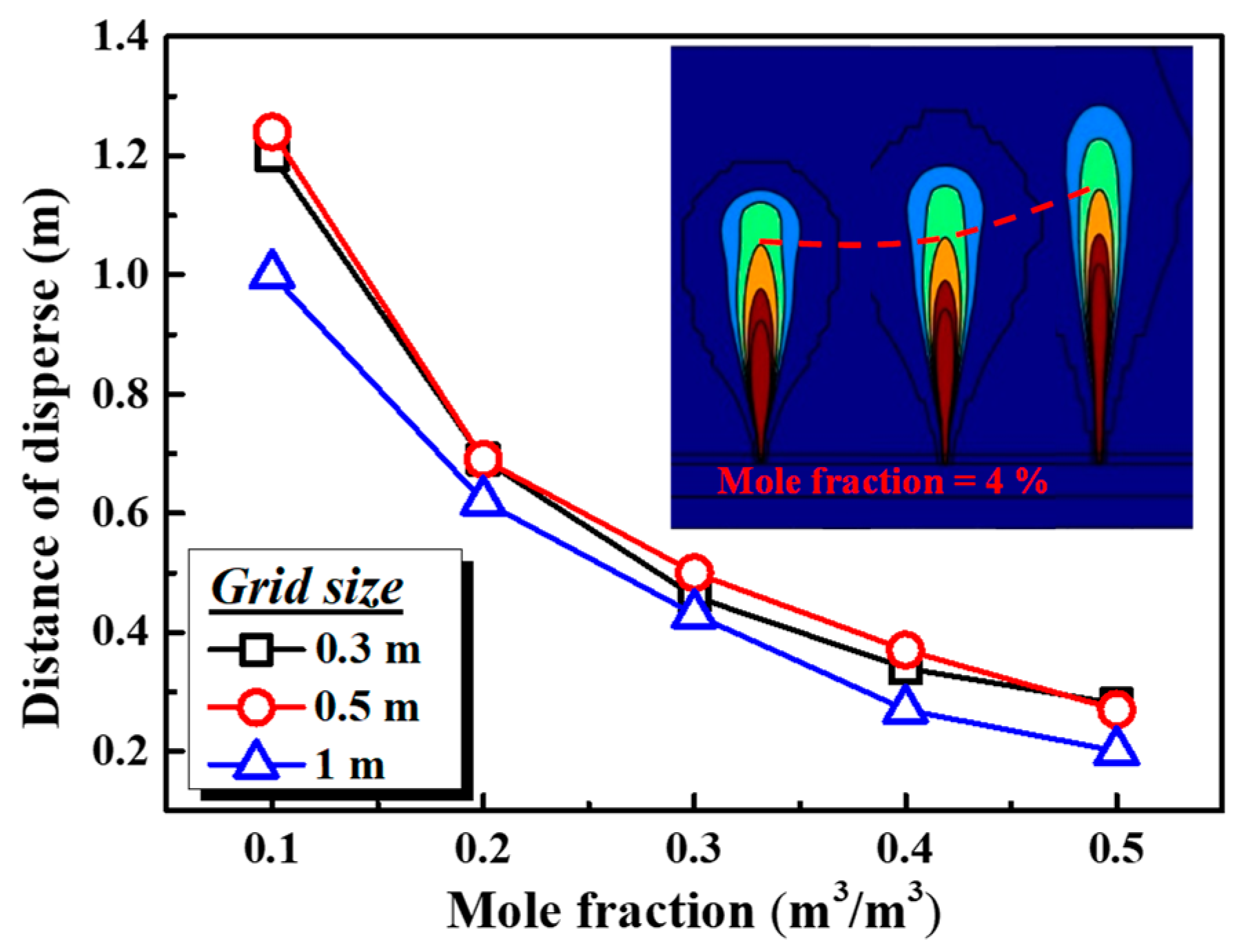
Figure 3.
Determination of the steady state.

Figure 4.
Dispersion distances of hydrogen at different leak hole sizes.

Figure 5.
Hydrogen stratification under relatively higher wind speeds (6 m/s and 10 m/s): (a) with a confined trench space; (b) under an unconfined open space.
Figure 5.
Hydrogen stratification under relatively higher wind speeds (6 m/s and 10 m/s): (a) with a confined trench space; (b) under an unconfined open space.
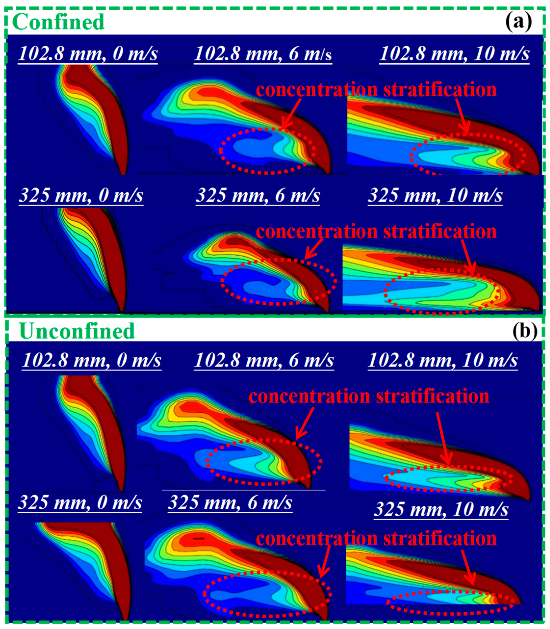
Figure 6.
Radiation distribution of hydrogen jet fire in confined and unconfined conditions.
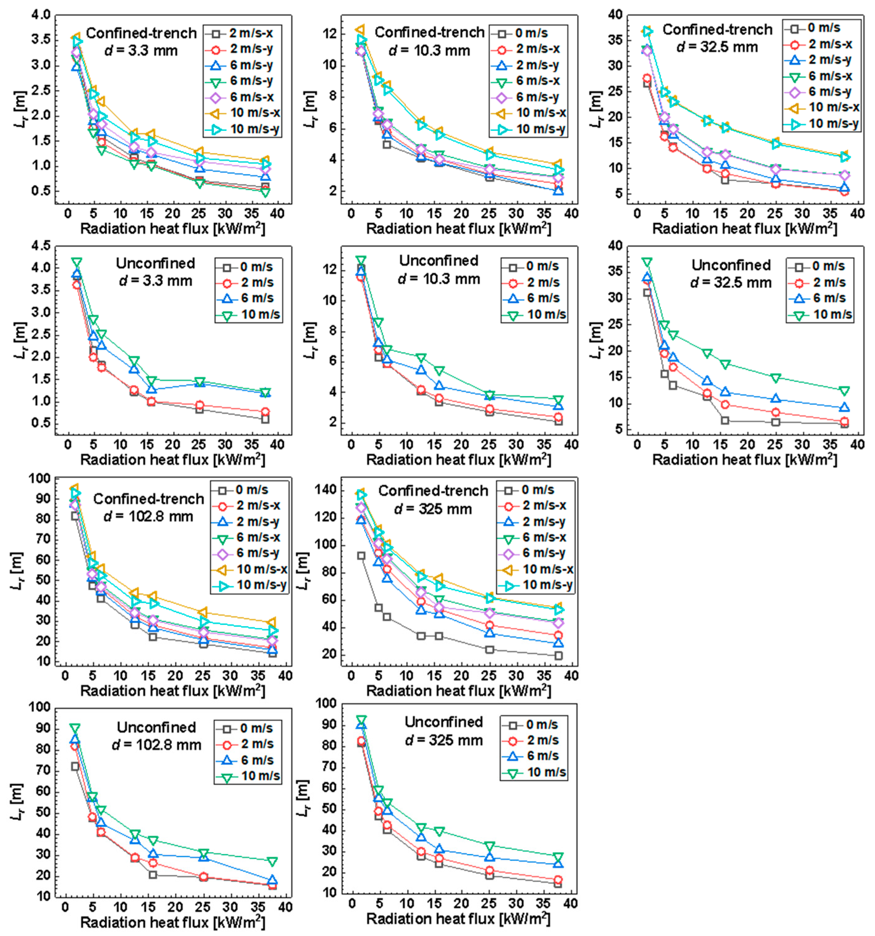
Figure 7.
A sketch of jet fires’ influential factors. (a) Unconfined; (b) confined trench.

Table 1.
Radiation heat flux criteria.
| (kW/m2) | Damage to Equipment | Damage to Humans |
|---|---|---|
| 35 | Failure of operation of equipment | 1% fatality (10 s), 100% fatality (60 s) |
| 25 | The lowest energy for wood burning under radiation with no flame | Serious burn (10 s), 100% fatality (60 s), 1% fatality (10 s) |
| 12.5 | The lowest energy for wood burning under radiation with flame | 1% fatality (60 s), first degree burn (10 s) |
| 6.3 | No effect | Influencing escape route |
| 4.7 | No effect | Influencing safety zone |
| 1.58 | No effect | No effect |
Disclaimer/Publisher’s Note: The statements, opinions and data contained in all publications are solely those of the individual author(s) and contributor(s) and not of MDPI and/or the editor(s). MDPI and/or the editor(s) disclaim responsibility for any injury to people or property resulting from any ideas, methods, instructions or products referred to in the content. |
© 2023 by the authors. Licensee MDPI, Basel, Switzerland. This article is an open access article distributed under the terms and conditions of the Creative Commons Attribution (CC BY) license (https://creativecommons.org/licenses/by/4.0/).
Share and Cite
MDPI and ACS Style
Lin, Y.; Ling, X.; Yu, A.; Liu, Y.; Liu, D.; Wang, Y.; Wu, Q.; Lu, Y. Modeling of Hydrogen Dispersion, Jet Fires and Explosions Caused by Hydrogen Pipeline Leakage. Fire 2024, 7, 8. https://doi.org/10.3390/fire7010008
AMA Style
Lin Y, Ling X, Yu A, Liu Y, Liu D, Wang Y, Wu Q, Lu Y. Modeling of Hydrogen Dispersion, Jet Fires and Explosions Caused by Hydrogen Pipeline Leakage. Fire. 2024; 7(1):8. https://doi.org/10.3390/fire7010008
Chicago/Turabian StyleLin, Yujie, Xiaodong Ling, Anfeng Yu, Yi Liu, Di Liu, Yazhen Wang, Qian Wu, and Yuan Lu. 2024. "Modeling of Hydrogen Dispersion, Jet Fires and Explosions Caused by Hydrogen Pipeline Leakage" Fire 7, no. 1: 8. https://doi.org/10.3390/fire7010008