Disjoining Pressure Derived from the Lennard–Jones Potential, Diffusion Equation, and Diffusion Coefficient for Submonolayer Liquid Film

Tokyo Institute of Technology, 10-4-1, Suginami-Ku, Tokyo 167-0022, Japan
Surfaces 2018, 1(1), 122-137; https://doi.org/10.3390/surfaces1010010
Submission received: 1 October 2018
/
Revised: 31 October 2018
/
Accepted: 2 November 2018
/
Published: 12 November 2018
Abstract
:In magnetic hard disk drives, it is important to evaluate the replenishment effect of a submonolayer lubricant film under a more severe condition that the head–disk spacing has to be reduced from the current 0.7 nm to ~0.5 nm. In contrast to the prevailing conventional diffusion equation validated for multilayer liquid film, the author has already proposed a new diffusion equation more suitable for submonolayer film by intuitively incorporating the density reduction effect in the submonolayer liquid film. This paper presents a rigorous derivation of the disjoining pressure (DP) from Lennard–Jones potential (LJP) and formulated the diffusion equation incorporating the DP. The difference in the rigorous DP and diffusion equation from the previous versions is negligibly small except in a small film thickness less than the van der Waals (vdW) distance. The theoretical relationship between the vdW distance in the DP and the molecular force equilibrium distance in the LJP is elucidated. Rigorous derivations of the DP and diffusion equation for multilayer liquid film from the LJP are also presented. The superiority of the submonolayer diffusion equation over the conventional equation in the submonolayer film regime is demonstrated by comparing their theoretical diffusion coefficients with Waltman’s experimental data.
1. Introduction
In the field of micro- and nanotribology, evaluating the boundary lubrication and replenishment effect of a submonolayer liquid film is becoming increasingly important. In particular, in hard disk drives, the perfluoropolyether (PFPE) lubricant thickness has decreased to one monolayer and the head flying height (clearance) above the lubricant surface has been reduced to the subnanometer level to decrease the head–medium spacing and thus increase the recording density [1]. The flying head clearance is controlled to decrease to the minimum allowable value during only read/write operations by means of the thermal flying height control (TFC) technique [2]. The clearance of the commercially available hard disk drives with the highest recording density is reduced to ~0.7 nm and is further required to be less than ~0.5 nm without spacing variation and deterioration of wear reliability of the head–disk interface. At such a small spacing, the probability of interaction and intermittent contact between the head surface and asperities on the disk surface increases owing to the combined effects of microwaviness and roughness of the disk surface [3].
To accommodate the increasingly severe conditions, boundary lubricant films with higher resistance to slider-induced disturbance and higher retention to the underlying carbon film via increased molecular polarity and bond ratio have been employed [4]. Although reduction of the mobile lubricant fraction contributes to preventing lubricant instability and transfer to the head surface, it was also reported that some fraction of mobile lubricant plays an essential role in reducing head wear [5,6]. This indicates that mobile lubricant molecules would have boundary lubrication effect at asperity contact and can replenish to depleted parts generated by intermittent asperity contacts. As a result, the bond ratio of monolayer lubricant film is increased to 80–90% in actual disk drives. Therefore, it is important to evaluate the diffusion effect of a submonolayer lubricant film.
Fundamental studies on the kinetics of a thin liquid film in relation to the disjoining pressure presented until the middle of 1990s were reviewed by de Gennes [7] and Oron et al. [8]. However, the replenishment ability of molecularly thin PFPE lubricant on magnetic disks has been evaluated from the spreading speed of the stepwise film boundary and the diffusion coefficient is often used as a measure of the mobility of thin lubricant film. A theoretical expression of diffusion flow for a thin liquid film was first proposed by Mate [9] by combining the disjoining pressure and Poiseuille flow equation. The diffusion characteristics of molecularly thin PFPE lubricant films with and without polar end groups were studied based on a simple diffusion equation by Karis and Tyndall [10] and Tyndall et al. [11]. In these papers, the disjoining pressure for the dispersive component was expressed as Πd = A/6πh3, where A is the Hamaker constant and h is the lubricant film thickness. For a polar lubricant such as Z-dol, the measured polar surface energy γp as a polynomial function of lubricant thickness h was additionally considered as a polar disjoining pressure Πp = ∂γp/∂h. Marchon and Karis [12] proposed an advanced diffusion equation using the disjoining pressure Πd = A/6π(h + d0)3 and showed that the diffusion characteristics of the steplike boundary of a non-polar lubricant layer with a thickness of a few nanometers can be quantitatively evaluated by this equation. Here d0 is the van der Waals (vdW) distance between diamond-like-carbon (DLC) substrate and PFPE lubricant film. This advanced disjoining pressure equation seems to be enlightened by the dispersive surface energy function of the form −A/12π(h + d0)2 proposed by Waltman et al. [13]. As PFPE lubricant film has been decreased to a monolayer thickness and the main fraction was bonded thereafter, a question arose whether the conventional diffusion equation based on the Poiseuille flow model and disjoining pressure for continuum medium can still hold for a submonolayer lubricant film.
Mate [14] investigated the spreading kinetics of PFPE lubricant nanodroplets with 0–8 hydroxyl functional groups on a carbon-coated magnetic disk surface. He found that when the central droplet dissipates into a pancake-shaped film, the spreading profile is well described by a diffusion equation derived from the Poiseuille flow model with zero slip for Fomblin-Z and Z-dol lubricants if the unknown viscosity is identified experimentally. The effective viscosities used to calculate the circular droplet profile for Z and Z-dol lubricants appeared consistent with those obtained by the blow-off experiment [15].
On the other hand, in [16], the replenishment speed of a depleted scar generated by 20 repeated touchdowns of a flying head slider on a commercially used disk surface was investigated, where a Z-Tetraol lubricant layer with a bonded layer thickness of 1.36 nm and an initial mobile lubricant thickness of 0.24 nm (the bond ratio is 0.85) was coated. After the touchdown test, the replenishment process of the depleted lubricant scar profile was evaluated using the conventional diffusion equation. It was found that the effective viscosity of a thin mobile lubricant film was estimated to be about a factor of 10 larger than the bulk viscosity at earlier elapsed time of a few hours of replenishment for the assumed value of A = 0.5 × 10⁻¹⁹ J. It was also found that the replenishment speed was reduced as the elapsed time increased to a few days. In that paper, the reflow speed of replenishment to a rectangular depleted scar was also investigated. Based on the general feature that replenishment time decreases proportionally to the square of the depleted scar width, a generic design chart for lubricant film was proposed. From this chart, we can evaluate the allowable width of scar in which 50% replenishment can be achieved after one revolution time of 8.3 ms (at 7200 rpm disk speed) as a function of the lubricant thickness and the value of A/μ (μ is the lubricant viscosity).
Thereafter, it was found that the increase in the apparent viscosity at the shallowed scar was caused by a permanent wear scar in the bonded layer generated by the severe repeated touchdown test [17]. However, there remains a question why the effective viscosity in the current author’s paper becomes relatively large compared with Mate’s research, although the discrepancy may be a partly result of the differences in lubricant tested and the experimental model. Moreover, there is a discrepancy in the definition of submonolayer film thickness between theory and experiment: the submonolayer film thickness is experimentally determined as a product of the monolayer thickness and the ratio of the measured density of the film to that of the bulk density, whereas this effect was not considered in the conventional disjoining pressure and diffusion equation. Accordingly, the author proposed a new disjoining pressure and flow equation modified by the density reduction effect on the Hamaker constant and mass flow equation for the submonolayer lubricant thickness. Incorporating the new disjoining pressure and mass flow equation with film-thickness-dependent viscosity function, a new diffusion equation that is more valid for the submonolayer film was formulated [17]. From this theory, it was found that the experimental replenishment profile could be calculated from the bulk viscosity if the effective viscosity is assumed to linearly increase to a few times larger than the bulk viscosity at the boundary of the bonded layer; moreover, approximately 30% of the depleted scar after 96 h was caused by wear of the bonded layer. It was also found that diffusion coefficient in a submonolayer regime can be evaluated by the new diffusion equation for a submonolayer lubricant film much better than the conventional diffusion equation. In this paper, the diffusion equation incorporating the new disjoining pressure and viscosity variation in the submonolayer film is called “submonolayer diffusion theory” or “submonolayer theory” for simplicity in contrast to the conventional theory for a continuous liquid film.
Recently, Waltman [18] measured the diffusion profile of a steplike submonolayer film of Z-Tetraol lubricant and calculated the diffusion coefficient in a region of submonolayer lubricant thickness. He demonstrated that the experimental diffusion coefficient for a submonolayer film thickness of 0.25–1.29 nm can be estimated more accurately by submonolayer diffusion theory than the conventional diffusion theory. Then, by using the experimental diffusion coefficients, Waltman performed a simulation study of how replenishment speeds are affected by various kinds of multiple depleted troughs caused by heat assisted magnetic recording.
In the present author’s previous paper [17], however, the modified disjoining pressure for a submonolayer film with reduced density was introduced intuitively rather than theoretically. In addition, the theoretical derivation of the conventional disjoining pressure is not clear to the best of the author’s knowledge for prior references. For this reason, this study aims to provide a scientific foundation to the disjoining pressures for both submonolayer and multilayer films by rigorous derivation from the Lennard–Jones potential (LJP). As a result, this paper can present a more rigorous expression of the disjoining pressure and resulting diffusion equation for both submonolayer and multilayer film. The superiority of this submonolayer diffusion theory is demonstrated by comparing the theoretical diffusion coefficient with Waltman’s experimental results [18].
2. Disjoining Pressure for Submonolayer Liquid Film
2.1. Analytical Model and Assumptions
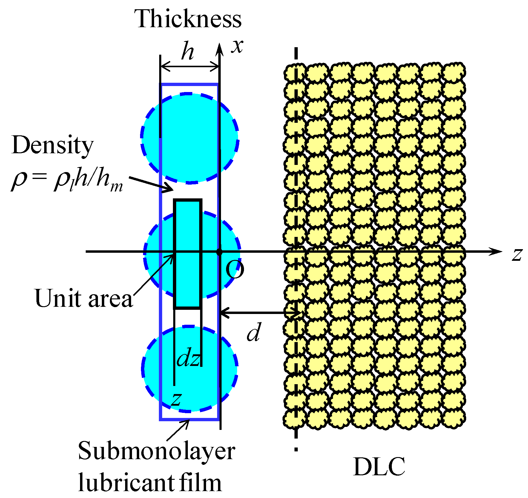
Figure 1 shows a schematic cross-sectional model of submonolayer lubricant film that is coated on the surface of a smooth solid half space with a distance of d. The solid material is considered to be DLC that is modeled as small compact DLC molecule balls. When lubricant molecules cover the DLC surface with nearly 100% coverage, the lubricant thickness is defined as a monolayer and is denoted by hm, which is nearly equal to the diameter of gyration. When lubricant is a submonolayer film, its mean thickness h is smaller than hm. In the experiments, the density ρh of the submonolayer is measured. Then, the submonolayer thickness h and its density ρh are respectively defined as
In Figure 1, the xy plane of the rectangular coordinates O-xyz is fixed on the bottom surface of submonolayer film and the z-axis is fixed in the direction of the solid half space.
2.2. Disjoining Pressure Derived from Attractive Term in LJP
As explained by Israelachvili [19], if the potential between one lubricant molecule located at x = y = z = 0 and a molecule in the solid at a distance r from the lubricant molecule is expressed as w(r) = −C/rn, the sum of the interactive energy between the liquid molecule and whole solid molecules is derived by integrating the effect of an annular region from z = d to ∞, and x = 0 to ∞. The integrated result is given by
Here, ρs is the number density of the DLC.
It is assumed in Figure 1 that the central position of each liquid molecule is located with a uniform probability in the region between z = 0 and −h. Then, the number of liquid molecules in a small volume of liquid with a unit area and a thickness of dz is given by . Therefore, the surface interaction energy W(d) between the submonolayer liquid film of unit area and the solid surface is given by
Here, corresponds to the Hamaker constant A for a multilayered continuous liquid film and DLC surface. Considering that the molecular pair potential of the attractive term of the LJP corresponds to n = 6, the interaction energy Wa(d) due to only the attractive term of the LJP is written as
Because Equation (4) represents the interaction energy between the submonolayer film with a thickness of h and the solid surface, the disjoining pressure Πsa (subscripts s and a denotes submonolayer theory and attractive term, respectively) due to the attractive term at a distance of d0 is given by
Equation (5) is valid in the region 0 < h ≤ hm. When the liquid film thickness h is larger than hm, we can obtain the disjoining pressure Πa for the continuous liquid film by replacing Ah/hm by A in Equation (5), as follows:
Here d0 is considered to be the mean distance between the mean center position of liquid molecules at the contacting film surface and the mean center position of solid surface molecules and corresponds to the averaged sum of vdW radii of liquid molecules and solid surface molecules. The quantity Πsa in Equation (5) is always negative when h > 0, and becomes zero in the second order of h when h → 0. In contrast, Πain Equation (6) becomes zero in the first order of h when h → 0. Further, it is unnatural that Πa approaches a constant value as h increases to infinity.
Note that the conventional disjoining pressure Πc1 for a continuous liquid film is obtained from Equation (6), by ignoring the second term, as follows:
Marchon and Karis [12] and Mate [14,20] used this disjoining pressure for the analysis of the spreading behavior of a steplike boundary of a non-polar lubricant film although the former researchers usually used the simpler disjoining pressure without considering d0 [7,8,9,10,11]. Although a detailed derivation process of this equation is not known, Πc1 always takes a positive value when A > 0. It takes a maximum value at h = 0 and becomes zero as h increases to infinity. Therefore, Equations (5) and (6) show completely different characteristics from Πc1. In submonolayer diffusion theory [17], the present author intuitively replaced the Hamaker constant A by Ah/hm because the Hamaker constant is proportional to the density of submonolayer film and used the disjoining pressure Πs1 of the form
Πs1 in Equation (8) becomes zero in the first order of h as h decreases to zero. This seems to be more reasonable than Πc1 in a submonolayer regime. Here Πs1 is always positive when A > 0.
2.3. Disjoining Pressure Derived from LJP
The term 1/d03 in Equations (5) and (6) is why Πsa in Equation (5) and Πa in Equation (6) have negative sign compared with Πs1 and Πc1 and Πa does not tend to zero as h increases. It is considered that the existence of this term is a result of the derivation only from attractive term in the LJP. Therefore, let us next derive the disjoining pressure from the LJP including both attractive and repulsive terms.
If the equilibrium distance of the interactive force between a pair of molecules is denoted as r0, the LJP between a pair of molecules is given by
Because Equation (3) was derived from a potential of the form w(r) = −C/rn, the surface interaction energy in Equation (3) due to the attractive term in Equation (9) corresponds to the case where C = 2εr06. Because the repulsive term in the LJP (9) is expressed as a potential w(r) = εr012/r12, the interactive energy Wr(d) due to the repulsive term can be obtained, by replacing C by −C r06/2 in Equation (3) and using n = 12 and , as follows:
Therefore, the disjoining pressure Πsr due to the repulsive term in the LJP at vdW distance of d0 is given by
Then, from the sum of Πsa in Equation (5) and Πsr in Equation (11), the total disjoining pressure Πst derived from the LJP becomes
In the region of film thickness larger than the monolayer (h ≥ hm), replacing Ah/hm by A, the total disjoining pressure Πt is given by
If the second term in the square brackets is not zero in Equation (13), Πt has a constant value as h increases to infinity and this result is unnatural. Therefore, the second term in the square bracket must be zero and thereby we have a condition
This is the relationship between the molecular equilibrium distance r0 in the LJP and mean vdW distance d0 between the liquid film and solid surface. Note that without this relationship, the disjoining pressure Πt in Equation (13) takes a constant value even at infinite liquid thickness. This implies that the relationship in Equation (14) is a necessary condition for consistently modeling the mutual interactions expressed by the LJP between discrete molecules as a simple equation with respect to the averaged physical quantities between continuous solid and liquid film.
When Equation (14) holds, the disjoining pressure Πs2 including both attractive and repulsive terms becomes, from Equation (12),
From Equation (13), the disjoining pressure Πc2 for a multilayer film is given by
The disjoining pressure Πs2 in Equation (15) for a submonolayer film always takes a positive value and becomes zero in the second order of h when h approaches zero. Because these features are consistent with Πs1, it can be said that Πs2 corresponds to the rigorous solution of the previous disjoining pressure Πs1 for submonolayer film. In Equation (16), Πc2 also has a positive value in the entire range of film thickness similar to the conventional disjoining pressure Πc1. Here Πc2 becomes zero in the first order of h as h decreases to zero and zero in the order of 1/h3 as h increases to infinity. Therefore, it can be said that Πc2 corresponds to the rigorous solution of the prevailing disjoining pressure Πc1. Although the derivation process of the conventional disjoining pressure Πc1 is not clear to the best of the author’s knowledge, the present author thought that the validity of Πc1 is not appropriate for submonolayer lubricant film [17]. This is because the disjoining pressure Πc1 takes a maximum value at zero lubricant film thickness. From this analytical study, however, it is found that the rigorous disjoining pressure Πc2 derived from the LJP becomes zero at h = 0. It is also found that Πc1 can be approximated from the solution effectively used in a film thickness region h ≥ 0.5d0 because the second term of Πc2 in Equation (16) becomes negligibly small.
To compare quantitatively the derived disjoining pressures, Πc1, Πc2, Πs1, and Πs2 normalized by A/6πd03 are plotted in Figure 2a,b as a function normalized film thickness h/d0. Here, it is assumed that d0 = 0.3 nm and hm = 4d0 = 1.2 nm. Figure 2b shows an enlarged illustration of Figure 2a to show the difference between Πs1 and Πs2. From Figure 2a it is clear that Πc2 takes a maximum value at h/d0 = ~0.25 and then approaches zero in contrast to Πc1. In the region where h/d0 > 0.5, Πc1 is very close to the rigorous disjoining pressure Πc2. In addition, it is also found from Figure 2b that the disjoining pressure Πs1 that was proposed in the previous paper [17] is very close to Πs2 where h/d0 > 0.5. Because it is assumed that hm = 4d0, Πs2 becomes equal to Πc2 at h/d0 = 4 as can be seen from Figure 2b. This means that the disjoining pressure for submonolayer theory is continuously connected with the conventional theory as the film thickness h exceeds the monolayer thickness hm.
3. Diffusion Equation Incorporating the Rigorous Disjoining Pressure
3.1. Diffusion Flow Model for Submonolayer Film
Although the Poiseuille flow model for submonolayer film and the derivation process of the one-dimensional diffusion equation have been explained in detail in the previous paper [17], the derivation process of the diffusion equation based on the Poiseuille flow model is explained briefly here.
Figure 3 shows a cross-section of a submonolayer liquid film on a solid surface and rectangular coordinates O-xz to analyze the liquid flow caused by the external pressure applied to the film surface and the disjoining pressure. The position z = 0 is chosen at the boundary with the solid surface. The monolayer thickness of the liquid is denoted by hm. The height of the film surface changes with respect to time t and position x and, thus, can be expressed as h(x, t). If we consider a small rectangular element of ABCD (dx × dz) close to the film surface as shown in Figure 3, the flow velocity u(z + dz) on the upper plane A–B is approximated by the mean velocity of molecules at the surface of h(z + dz). Similarly, it is considered that the flow velocity u(z) can be approximated by the mean molecular velocity at the surface of h(z). If liquid molecules do not slip perfectly, u(z) and u(z + dz) can have different values, so that the mean velocity can have the first derivative with respect to z. Then, we can assume that the shear stress τz acting on the z plane is proportional to du/dz, similar to a Newtonian flow. If we define this proportional constant as the viscosity μz, we can write
Here, the viscosity μz is generally a function of z.
Although we can treat any thickness-dependent viscosity model by using a polynomial expression of z, we assume here that the effective viscosity μz changes linearly from μ0 to μm for the sake of analytical simplicity, as follows:
where α is given by
Note that the definition of α is a non-dimensional quantity different from that in the previous paper [17].
Next consider the equilibrium condition of all forces applied to the rectangular element ABCD shown in Figure 3. The shear forces τz and τz+dz given by Equation (17) are applied to the lower and upper surfaces, respectively, of the element. The pressure p is caused by the ambient pressure, disjoining pressure, and capillary pressure. These pressures are a function of only x. Because pxdz and px+dxdz are applied on the left- and right-hand sides of the element, as shown in Figure 2, we can obtain the basic equation of equilibrium of the form
3.2. Derivation of the Diffusion Equation
By integrating Equation (20) by z and considering a free surface of the submonolayer film, we obtain
Substituting Equation (18) into Equation (21) and integrating it, we can obtain the flow velocity u. In the experimental and theoretical investigation of spreading kinetics of a small droplet in the submonolayer thickness regime, Mate [14,20] found that spreading profiles can be evaluated by the Poiseuille flow model without slip at the solid surface. Therefore, by determining the integral constant to satisfy the no-slip condition at the solid surface, we obtain the velocity in the following form:
The mass conservation equation of the liquid film at x is given by
Denoting the integration part of the second term by q and using Equation (1) for the density ρ, we obtain
Putting Equations (1) and (24) into Equation (23), we can obtain the diffusion equation of the form
where
In the spreading of the steplike liquid boundary and replenishment flow of a depleted groove in a molecularly thin liquid film, it is known that the disjoining pressure plays a dominant role and the capillary pressure can be ignored [16]. Because a higher disjoining pressure at a thinner film thickness has the effect of increasing the film thickness compared with the neighboring thickness at lower disjoining pressure, there is a relation of p = −Π. By substituting the rigorous disjoining pressure p = −Πs2 and approximated pressure p = −Πs1 into Equation (25), we can obtain the diffusion equation for submonolayer liquid film of the form
Here, J(h) for Πs2 and Πs1 are respectively given by
On the other hand, if we put p = −Πc1 into the conservation equation of the Poiseuille flow for multilayer liquid film, we can obtain the conventional diffusion equation of the form
By using the rigorous disjoining pressure Πc2 we can obtain
Equation (31) corresponds to the rigorous diffusion equation valid for a liquid film greater than monolayer thickness. Note that when A > 0, the diffusion coefficient becomes positive in Equations (30) and (31), resulting in normal diffusion flow. However, because Js1 and Js2 become negative when h < ~d0/2, this implies that there is a limiting liquid thickness that cannot spread.
4. Comparison of the Diffusion Coefficient Between Theories and Experiment
4.1. Theoretical Diffusion Coefficient
The lubrication effect of a thin lubricant film on the head–disk interface is considered to be strongly influenced by the flow speed of replenishment to a depleted groove caused by intermittent asperity contact. The mobility or replenishment speed of a lubricant film has been evaluated by theoretical and experimental diffusion coefficients in the typical diffusion equation model [17,21,22]. Recently, Waltman [18] measured the diffusion coefficient of a steplike boundary of submonolayer lubricant film and compared the calculated diffusion profile with experimental profiles. He also compared the experimentally measured diffusion coefficient with theoretical ones and found that the experimental diffusion coefficients agree well with those calculated from submonolayer diffusion theory [17] compared with the conventional theory.
Therefore, we next show the theoretical diffusion coefficients for both submonolayer theory and conventional theory and compare them with Waltman’s experimental data. From Equations (27)–(29), the rigorous diffusion coefficient Ds2(h) for submonolayer theory with disjoining pressure Πs2 is written as
By using I(h) in Equation (26) and Js1(h) in Equation (29), the diffusion coefficient Ds1(h) for Πs1 becomes,
On the other hand, the diffusion coefficient Dc1(h) for the conventional disjoining pressure Πc1 in Equation (7) is given by
The diffusion coefficient Dc2(h) for the rigorous conventional disjoining pressure Πc2 in Equation (31) is
4.2. Calculated Diffusion Coefficients and Comparison with Experimental Ones
Waltman [18] measured the diffusion coefficient of submonolayer film of Z-Tetraol (molecular weight 2200) PFPE lubricant. He measured the spreading profile variations of steplike boundaries whose initial lubricant thicknesses were 1.29, 0.97, 0.74, 0.51, and 0.25 nm, and calculated the diffusion coefficients at those lubricant film thicknesses. Because Waltman considered the thickness of monolayer of Z-Tetraol is 2.1 nm, hm = 2.1 nm is used in the calculations here unless otherwise noted. Marchon and Karis [12] used 0.317 nm for the vdW distance d0. Fukuda et al. [23] estimated that the force equilibrium distance of the non-bonded pair potential of a PFPE film-coated carbon surface was 0.46 nm based on coarse-grained molecular dynamics analysis. If we assume r0 = 0.46 nm, we obtain d0 = 0.29 nm. Mate [14] used d0 = 0.3 nm when theoretically evaluating the diffusion profiles of a small droplet. Referring to these values, we use d0 = 0.3 nm in the following calculation.
Figure 4 illustrates a comparison of the theoretical diffusion coefficients Ds1(h), Ds2(h), Dc1(h), Dc2(h), and Waltman’s experimental values. The common parameter A/6πμm of theoretical diffusion coefficients is determined so that Ds1(h), Ds2(h), Dc1(h), and Dc2(h) can coincide with the experimental value of D = 7.69 × 10⁻¹³ m2/s at h = 1.29 nm. Because the actual viscosity ratio is not known, we assume that rμ = μm/μ0 = 1. The effect of rμ on the diffusion coefficient functions is small as shown in Figure 5.
We note in Figure 4 that the diffusion coefficient Ds2 of submonolayer diffusion theory plotted by a black solid line shows excellent agreement with experimental values plotted by triangular symbols. The dashed line indicating Ds1 is very close to Ds2 in the region h > d0 and can be used as a good approximated solution for Ds2. The black dotted line shows Ds1 when d0 = 0.2 nm and rμ = 0.3 are used as in the same conditions as Waltman compared Ds2 with the experimental data [18]. We note that Ds2 tends to deviate from the experimental data to the upper side in the lower thickness region. In his paper, A/6πμm was determined so that Ds1(h) can coincide with the experimental diffusion coefficients at h = 0.25 and 0.51 nm. Therefore, Ds1(h) at h = 7.4, 9.7, 12.9 nm deviates to the lower side of the experimental values to some extent. From these results it is clear that Ds2 and Ds1 can agree well with experimental values when a reasonable value of the vdW distance of 0.3 nm is used for calculation.
In contrast, Dc2 and Dc1, depicted respectively by blue solid and dashed lines, do not decrease until h decreases to ~0.4 nm and show characteristics completely different from the experimental values. This is because Dc1 takes a maximum value at h = 3d0 = 0.9 nm and Dc2 is very close to Dc1. The difference between Dc2 and Dc1 is less than 5% in the region h > d0, similarly to the relationship between Ds2 and Ds1. The blue dotted line indicates Dc1 when d0 = 0.2 nm. In this case Dc1 takes a maximum value at h = 0.6 nm and thus deviates further from the experimental results. From the comparison between theory and experiment in Figure 5, it can be said that the submonolayer diffusion equation including the decrease in density can evaluate the experimental diffusion coefficient function. It is also confirmed that the submonolayer diffusion equation using disjoining pressure derived from the LJP is more valid for the kinetics of submonolayer liquid film.
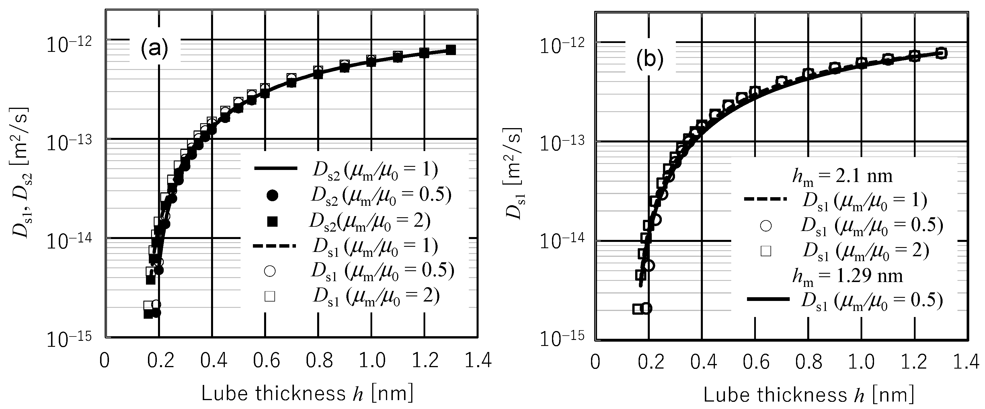
The effects of rμ (=μm/μ0) and hm on the diffusion coefficient function for submonolayer theory are shown in Figure 5 when d0 = 0.3 nm. Figure 5a shows Ds1 and Ds2 for various values of rμ when hm = 2.1 nm. Here rμ is changed as 0.5, 1, and 2. The solid and dashed lines depicting Ds2 and Ds1 for rμ = 1, respectively, are the same as shown in Figure 4. Here Ds2 for rμ = 0.5 depicted by closed circles is almost the same as that for rμ = 1, whereas Ds2 for rμ = 2 depicted by closed squares is slightly larger than Ds2 for rμ = 1 in the region where h < 0.4 nm. For rμ = 0.5, Ds1 (open circles) becomes slightly smaller than that for rμ = 1 in a range of small h value and Ds1 for rμ = 2 (open squares) becomes slightly larger than that for rμ = 1 in a range of large h values.
Figure 5b shows the effect of hm on diffusion coefficient function Ds1. Because the Ds1 is overlapped with Ds2 and is difficult to distinguish from Ds2 in Figure 5a, the same results of Ds1 for hm = 2.1 nm are plotted in Figure 5b. When hm = 1.29 nm and rμ = 0.5, Ds1 is comparatively plotted by a solid line. From a comparison between the open circle and solid line, we note that Ds1 decreases only slightly in the range h > 0.3 nm and increases slightly in the range h < 0.3 nm when hm is decreased by 61%. The effect of hm on the diffusion coefficient is very small. Accordingly, it can be said from Figure 4 and Figure 5a,b that the diffusion coefficients Ds1 and Ds2 are hardly influenced by rμ and hm if the physical parameter Arμ/μmhm is determined so that the theoretical diffusion coefficient coincides with the experimental value at a representative liquid film thickness.
The theoretical diffusion coefficients shown in Figure 4 and Figure 5 were calculated by determining A/μm in such a way that they coincide with the experimental diffusion coefficient at an arbitrarily chosen film thickness of h = 1.29 nm after specifying d0 and hm. Table 1 lists the value of A/μm determined in this manner for four different diffusion coefficients and effective bulk viscosities corresponding to typical values of the Hamaker constant when d0 = 0.3 nm. The Hamaker constant A = 0.47 × 10⁻¹⁹ J is the value for the dispersive surface pressure in the DLC–PFPE film–air layer calculated from Lifshitz theory [24]. Because the Hamaker constant calculated from Lifshitz theory is based on the assumption that each medium is continuous material, the effective Hamaker constant for the dispersive surface energy γd(h) of molecularly thin lubricant film is quantified experimentally by fitting a mathematical expression of the form to the measured surface energy function.
Here γ0 is the surface energy of bulk lubricant and A* is an effective Hamaker constant [25,26,27]. Waltman et al. [26] evaluated the effective Hamaker constant of Z-Tetraol (molecular weight is 2000) to be 1.9 × 10⁻¹⁹ J and used this value in [18].
On the other hand, Tani et al. [27] experimentally evaluated A* to be 4.8 × 10⁻¹⁹ J. Therefore, the bulk viscosities were calculated for the Hamaker constant values of 0.47 × 10⁻¹⁹ and 1.9 × 10⁻¹⁹ J in Table 1. The effect of polar surface energy on diffusion coefficient function was ignored here because it seemed to have a minor effect compared with the dispersive component, particularly on disjoining pressure [26,27].
From this table, we note that the values of A/μm and the estimated effective viscosity for Dc1 and Dc2 and those for Ds1 and Ds2 are almost the same values within three digits. Compared with conventional theory, submonolayer theory estimates a smaller viscosity by one fifth even when rμ = 1. This is because the effective Hamaker constant for submonolayer theory is evaluated to a reduced value owing to the decreased liquid density.
In cases of Ds1 and Ds2, the ratios of the estimated bulk viscosity μm at rμ = μm/μ0 = 1, 0.5, and 2 become 1, 0.54, and 1.75, respectively. This relationship between rμ and μm is reasonable. From the estimated bulk viscosities for hm = 1.29 and 2.1 nm, we note that the effective viscosity can be estimated as inversely proportional to the effective molecular thickness hm.
If we assume A = 0.47 × 10⁻¹⁹ J and rµ = 0.5, the estimated bulk viscosity is 0.107 Pa∙s for hm = 2.1 nm and 0. 186 Pa∙s for hm = 1.29 nm. When we use A = 1.9 × 10⁻¹⁹ J [26], however, the bulk viscosity is evaluated to be 0.751 Pa∙s. If we use A = 4.8 × 10⁻¹⁹ J [27], we can obtain µm = 1.9 Pa∙s. Because the bulk viscosity of Z-Tetraol is estimated to be around 1 Pa∙s, it can be said that the submonolayer diffusion theory results in the more realistic relationship between Hamaker constant and bulk viscosity compared with the conventional diffusion theory. Because the submonolayer diffusion function can agree well with the experimental one in a wide range of submonolayer film thickness h by using the effective Hamaker constant, it is inferred that the second derivative of the polar surface energy with respect to film thickness is negligibly small compared with that of the dispersive surface energy in the submonolayer thickness region [26,27].
According to the experimental and theoretical study (conventional diffusion equation) of the spreading profile and speed of a pancake-type droplet performed by Mate [14], it was found that the effective viscosity of non-polar PFPE film of Z-03 is estimated to be one order of magnitude smaller than the bulk viscosity when A = 0.4 × 10⁻¹⁹ J is assumed, whereas that of a polar PFPE film of Z-dol is estimated to be twice as large as the bulk viscosity. Therefore, it can be said that submonolayer diffusion theory is more appropriate for evaluating the spreading characteristics of non-polar submonolayer liquid film than the conventional theory.
For polar liquid film that has some fraction of bonded layer, proper evaluation methods of the effective Hamaker constant and effective viscosity for submonolayer film remain to be studied. These problems are expected to be elucidated by the molecular dynamics analysis. In Waltman’s experiment, about half of the Z-Tetraol film thickness was bonded on the DLC surface. Therefore, there remains a question whether the effective film thickness can be regarded as the total film thickness.
Regardless of some unclear problems that remain to be studied, it can be said that this study could provide the physical foundation of not only the submonolayer diffusion equation but also the conventional diffusion equation. It has been revealed that the diffusion coefficient function derived from the submonolayer diffusion theory can predict quantitatively the experimental diffusion coefficient in a small film thickness region down to the vdW distance if the physical parameter A/μm is identified by the experimental diffusion coefficient at a certain film thickness.
5. Conclusions
In this study, the disjoining pressure for a submonolayer liquid film coated on a solid surface has been derived strictly from the LJP. Incorporating the rigorous disjoining pressure, a one-dimensional diffusion equation for submonolayer liquid film considering the reduction of liquid density has been formulated. Rigorous mathematical expressions of the disjoining pressure and diffusion equation for multilayer liquid film model have also been presented. Diffusion coefficient functions of rigorous diffusion equations for submonolayer and multilayer liquid film model have been presented and compared with those of previous submonolayer diffusion equations and the conventional diffusion equation. The validity of the new diffusion coefficient has been examined by comparing the theoretical results with Waltman’s experimental data. Important results obtained in this study can be summarized as follows.
- The disjoining pressure for a submonolayer liquid film model derived from the LJP and diffusion equation for submonolayer liquid film incorporating the new disjoining pressure is a rigorous mathematical solution for the disjoining pressure and diffusion equation proposed previously. It was found that the previous submonolayer theory is a good approximated expression of the rigorous submonolayer theory in the region of film thickness above d0.
- From the axiomatic condition that the disjoining pressure must be zero at infinite film thickness, the mean vdW distance d0 of the liquid–solid interface must be 0.637 times the molecular equilibrium distance in LJP.
- The conventional disjoining pressure for a multilayer continuous liquid film including the vdW distance d0 cannot be derived from only the adhesive term of the LJP. The disjoining pressure rigorously derived from the LJP contains an additional term. Although the disjoining pressure derived from the LJP gives almost the same value as the conventional version in the region of film thickness larger than 0.5d0, it exhibits different behavior for a film thickness smaller than 0.5d0 and becomes zero at zero film thickness in contrast to the conventional disjoining pressure that has a maximum value at zero film thickness. It is considered that the disjoining pressure derived from the LJP is more reasonable.
- Four diffusion coefficients Ds2 (rigorous submonolayer theory), Ds1 (approximated submonolayer theory), Dc2 (rigorous continuous layer theory), and Dc1 (conventional continuous layer theory) have been compared with Waltman’s experimental diffusion coefficients by identifying the multiplication factor A/μm from the experimental diffusion coefficient value at 1.29 nm film thickness. When the presumable value of 0.3 nm is used for d0, Ds2 and Ds1 showed excellent agreement with the experimental data in the entire range of measured film thickness although Ds1 exhibited a slightly higher value in the region of film thickness less than d0. In contrast, Dc2 and Dc1 showed quantitatively and qualitatively different behaviors from the experimental data. This is because Dc2 and Dc1 take maximum values at a film thickness of ~3d0. As a result, it can be concluded that the spreading, diffusion, and replenishment behaviors of submonolayer liquid film can be evaluated by submonolayer theory if the amplification factor A/μm is identified from an arbitrarily chosen experimental value.
Acknowledgments
This study was supported by the JSPS Grant-in-Aid for Scientific Research (C) No. 16K06039.
Conflicts of Interest
The authors declare no conflicts of interest.
Nomenclature
| A | Hamaker constant for a multi-layer lubricant film coated on a solid surface [J] |
| D | Diffusion coefficient [m2/s] |
| O-xyz | Rectangular coordinate system for lubricant flow analysis |
| d | Mean distance between the liquid film and solid surface [m] |
| d0 | Mean van der Waals distance between the liquid film and solid surface [m] |
| h | Local thickness of the liquid film [m] |
| hm | Thickness of the monolayer of liquid film [m] |
| p | Pressure in the liquid film [Pa] |
| rμ | = μm/μ0 |
| t | Time [s] |
| u | Local velocity within the liquid film [m] |
| Π | Disjoining pressure [Pa] |
| α | = rμ − 1 |
| μz | Local viscosity of the submonolayer liquid film at a height of z [Pa·s] |
| μ0 | Effective viscosity at the solid surface [Pa·s] |
| μm | Viscosity of the liquid film for monolayer and multilayer liquid film [Pa·s] |
| ρl | Density of the bulk liquid [kg/m3] |
| ρh | Density of the submonolayer liquid film [kg/m3] |
References
- Xu, J.; Shimizu, Y.; Furukawa, M.; Li, J.; Sano, Y.; Shiramatsu, T.; Aoki, Y.; Matsumoto, H.; Kuroki, K.; Kohira, H. Contact/clearance sensor for HDI subnanometer regime. IEEE Trans. Magn. 2014, 50, 114–118. [Google Scholar] [CrossRef]
- Kurita, T.; Shiramatsu, K.; Miyake, A.; Kato, M.; Soga, H.; Tanaka, S.; Saegusa, S.; Suk, M. Active flying-height control slider using MEMS thermal actuator. Microsyst. Technol. 2006, 12, 369–375. [Google Scholar] [CrossRef]
- Canchi, S.V.; Bogy, D.B. Slider-lubricant interactions and lubricant distribution for contact and near contact recording conditions. IEEE Trans. Magn. 2011, 47, 1842–1848. [Google Scholar] [CrossRef]
- Marchon, B. Lubricant Design Attributes Subnanometer Head-Disk Clearance. IEEE Trans. Magn. 2009, 45, 872–876. [Google Scholar] [CrossRef]
- Chen, Y.-K.; Murthy, A.N.; Pit, R.; Bogy, D.B. Angstrom scale wear of the air-bearing sliders in hard disk drives. Tribol. Lett. 2014, 54, 273–278. [Google Scholar] [CrossRef]
- Matthes, L.; Brunner, R.; Knigge, B.; Talke, F.E. Head wear of thermal flying height control sliders as a function of bonded lubricant ratio, temperature, and relative humidity. Tribol. Lett. 2015, 60, 39. [Google Scholar] [CrossRef]
- de Gennes, P.G. Wetting: Statics and dynamics. Rev. Mod. Phys. 1985, 57 Pt 1, 827–863. [Google Scholar] [CrossRef]
- Oron, A.; Davis, S.H.; Bankoff, S.G. Long-scale evolution of thin liquid films. Rev. Mod. Phys. 1997, 69, 931–980. [Google Scholar] [CrossRef]
- Mate, C.M. Application of disjoining and capillary pressure to liquid lubricant films in magnetic recording. J. Appl. Phys. 1992, 72, 3084–3090. [Google Scholar] [CrossRef]
- Karis, T.E.; Tyndall, G.W. Calculation of spreading profiles for molecularly-thin films from surface energy gradients. J. Non-Newton. Fluid Flow 1999, 82, 287–302. [Google Scholar] [CrossRef]
- Tyndall, G.W.; Karis, T.E.; Jhon, M.S. Spreading profiles of molecularly thin perfluoro-polyether films. Tribol. Trans. 1999, 42, 463–470. [Google Scholar] [CrossRef]
- Marchon, H.; Karis, T.E. Poiseuille flow at a nanometer scale. Europhys. Lett. 2006, 74, 294–298. [Google Scholar] [CrossRef]
- Waltman, R.J.; Tyndall, G.W.; Pacansky, J. Computer-modeling study of the interactions of Zdol with amorphous carbon surfaces. Langmuir 1999, 15, 6470–6483. [Google Scholar] [CrossRef]
- Mate, C.M. Spreading kinematics of lubricant droplets on magnetic recording disks. Tribol. Lett. 2013, 51, 385–395. [Google Scholar] [CrossRef]
- Scarpulla, M.A.; Mate, C.M.; Carter, M.D. Air shear driven flow of thin perfluoropolyether polymer films. J. Chem. Phys. 2003, 118, 3368–3375. [Google Scholar] [CrossRef]
- Ono, K. Replenishment speed of depleted scar in submonolayer lubricant. Tribol. Lett. 2013, 52, 123–195. [Google Scholar] [CrossRef]
- Ono, K. Diffusion equation for spreading and replenishment in submonolayer lubricant film. Tribol. Lett. 2015, 57, 13. [Google Scholar] [CrossRef]
- Waltman, R.J. Z-Tetraol reflow in heat-assisted magnetic recording. Tribol. Online 2016, 11, 50–60. [Google Scholar] [CrossRef]
- Israelachvili, J.N. Intermolecular and Surface Forces, 2nd ed.; Academic Press: London, UK, 1992. [Google Scholar]
- Mate, C.M. Anomalous diffusion kinetics of the precursor film that spreads from polymer droplets. Langmuir 2012, 28, 16821–16827. [Google Scholar] [CrossRef] [PubMed]
- Ma, X.; Gui, J.; Grannen, K.J.; Smoliar, L.A.; Marchon, B.; Jhon, M.S.; Bauer, C.L. Spreading of PFPE lubricants on carbon surfaces: effect of hydrogen and nitrogen content. Tribol. Lett. 1999, 6, 9–14. [Google Scholar] [CrossRef]
- Ma, X.; Gui, J.; Smoliar, L.; Grannen, K.; Marchon, B.; Bauer, C.L.; Jhon, M.S. Complex terraced spreading of perfluoropolyalkylether films on carbon surfaces. Phys. Rev. E 1999, 59, 723–727. [Google Scholar] [CrossRef]
- Fukuda, M.; Zhang, H.; Ishiguro, T.; Fukuzawa, K. Structure-based coarse-graining for inhomogeneous liquid polymer systems. J. Chem. Phys. 2013, 139, 054901. [Google Scholar] [CrossRef] [PubMed]
- Matsuoka, H.; Ohkubo, S.; Fukui, S. Correction expression of the van der Waals pressure for multilayered system with application to analyses of static characteristics of flying head sliders with an ultrasmall spacing. Microsyst. Technol. 2005, 11, 824–829. [Google Scholar] [CrossRef]
- Waltman, R.J.; Deng, H.; Wang, G.J.; Zhu, H.; Tyndall, G.W. The effect of PFPE film thickness and molecular polarity on the pick-up of disk lubricant by a low-flying slider. Tribol. Lett. 2010, 39, 211–219. [Google Scholar] [CrossRef]
- Waltman, R.J.; Newman, J.; Guo, X.-C.; Burns, J.; Witta, C.; Amo, M. The effect of UV irradiation on the Z-Tetraol boundary lubricant. Tribol. Online 2012, 7, 70–80. [Google Scholar] [CrossRef]
- Tani, H.; Mitsutome, T.; Tagawa, N. Adhesion and friction behavior of magnetic disks with ultrathin perfluoropolyether lubricant films having different end-groups measured suing pin-on-disk test. IEEE Trans. Magn. 2013, 49, 2638–2644. [Google Scholar] [CrossRef]
Figure 1.
Schematic molecular model of submonolayer lubricant film and diamond-like-carbon (DLC).

Figure 2.
(a) Comparison of disjoining pressure Πs1 of Equation (8), Πs2 of Equation (15), Πc1 of Equation (7), and Πc2 of Equation (16); (b) Enlarged view of (a).
Figure 2.
(a) Comparison of disjoining pressure Πs1 of Equation (8), Πs2 of Equation (15), Πc1 of Equation (7), and Πc2 of Equation (16); (b) Enlarged view of (a).

Figure 3.
Coordinate system and forces acting on a small liquid element in a submonolayer film near a liquid surface.
Figure 3.
Coordinate system and forces acting on a small liquid element in a submonolayer film near a liquid surface.

Figure 4.
Comparison of various theoretical diffusion coefficient functions Ds1(h), Ds2(h), Dc1(h), and Dc2(h) (hm = 2.1 nm and rμ = 1) and experimental data [18].
Figure 4.
Comparison of various theoretical diffusion coefficient functions Ds1(h), Ds2(h), Dc1(h), and Dc2(h) (hm = 2.1 nm and rμ = 1) and experimental data [18].

Figure 5.
Effects of the viscosity ratio and monolayer thickness on diffusion coefficient functions. (a) Effects of viscosity ratio μm/μ0 on Ds1(h) and Ds2(h); (b) Effects of monolayer thickness hm on Ds1(h).
Figure 5.
Effects of the viscosity ratio and monolayer thickness on diffusion coefficient functions. (a) Effects of viscosity ratio μm/μ0 on Ds1(h) and Ds2(h); (b) Effects of monolayer thickness hm on Ds1(h).

Table 1.
Estimated physical parameter values calculated from the experimental diffusion coefficient at h = 1.29 nm.
Table 1.
Estimated physical parameter values calculated from the experimental diffusion coefficient at h = 1.29 nm.
| Diffusion Coefficient | Dc1 | Dc2 | Ds1 | Ds2 | |||||
|---|---|---|---|---|---|---|---|---|---|
| hm [nm] | 2.1 | 2.1 | 2.1 | 1.29 | 2.1 | ||||
| rμ (=μm/μ0) | 1 | 1 | 1 | 0.5 | 2 | 0.5 | 1 | 0.5 | 2 |
| A/μm [×10−19 m3/s] | 0.432 | 0.432 | 2.385 | 4.384 | 1.362 | 2.528 | 2.385 | 4.385 | 1.362 |
| μm [Pa∙s] (A = 0.47 × 10⁻¹⁹ J) | 1.089 | 1.089 | 0.197 | 0.107 | 0.345 | 0.186 | 0.197 | 0.107 | 0.345 |
| μm [Pa∙s] (A = 1.9 × 10⁻¹⁹ J) | 4.403 | 4.402 | 0.797 | 0.433 | 1.395 | 0.751 | 0.796 | 0.433 | 1.395 |
© 2018 by the author. Licensee MDPI, Basel, Switzerland. This article is an open access article distributed under the terms and conditions of the Creative Commons Attribution (CC BY) license (http://creativecommons.org/licenses/by/4.0/).
Share and Cite
MDPI and ACS Style
Ono, K. Disjoining Pressure Derived from the Lennard–Jones Potential, Diffusion Equation, and Diffusion Coefficient for Submonolayer Liquid Film. Surfaces 2018, 1, 122-137. https://doi.org/10.3390/surfaces1010010
AMA Style
Ono K. Disjoining Pressure Derived from the Lennard–Jones Potential, Diffusion Equation, and Diffusion Coefficient for Submonolayer Liquid Film. Surfaces. 2018; 1(1):122-137. https://doi.org/10.3390/surfaces1010010
Chicago/Turabian StyleOno, Kyosuke. 2018. "Disjoining Pressure Derived from the Lennard–Jones Potential, Diffusion Equation, and Diffusion Coefficient for Submonolayer Liquid Film" Surfaces 1, no. 1: 122-137. https://doi.org/10.3390/surfaces1010010