
Combined PEO and Spray Pyrolysis Coatings of Phosphate and ZnO for Enhancing Corrosion Resistance in AZ31 Mg Alloy

 ,
,  , , and
Abstract
:1. Introduction
2. Materials and Methods
3. Results
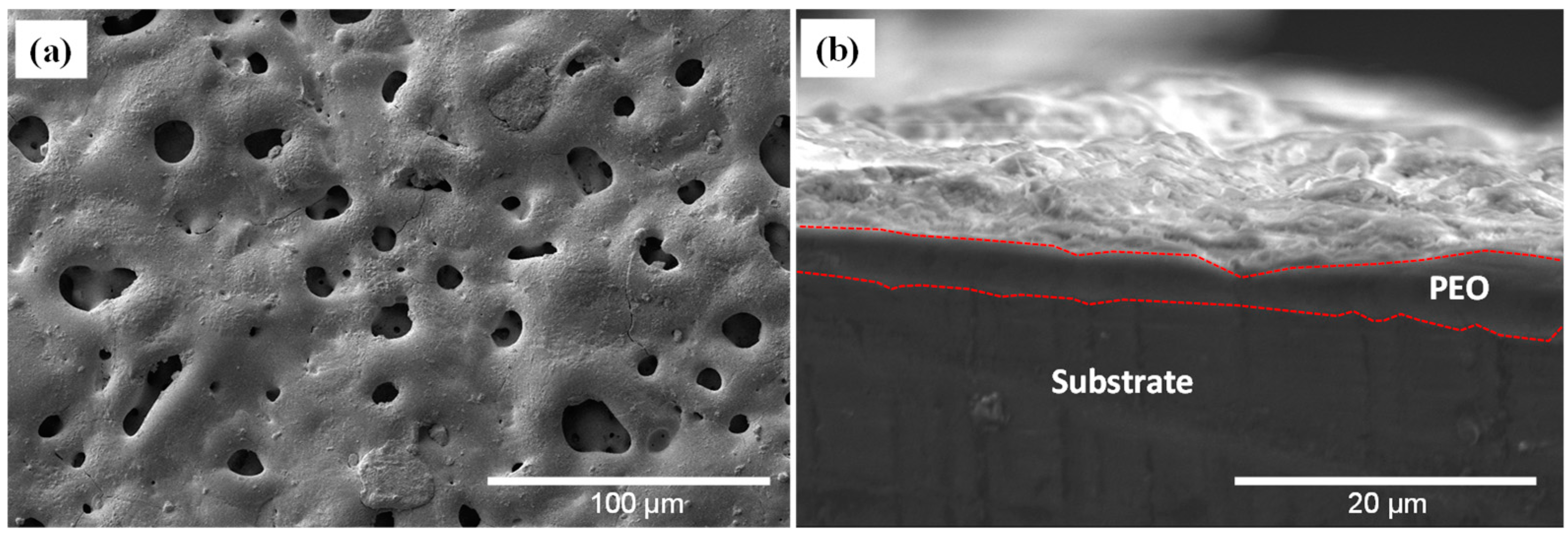
3.1. SEM Imaging
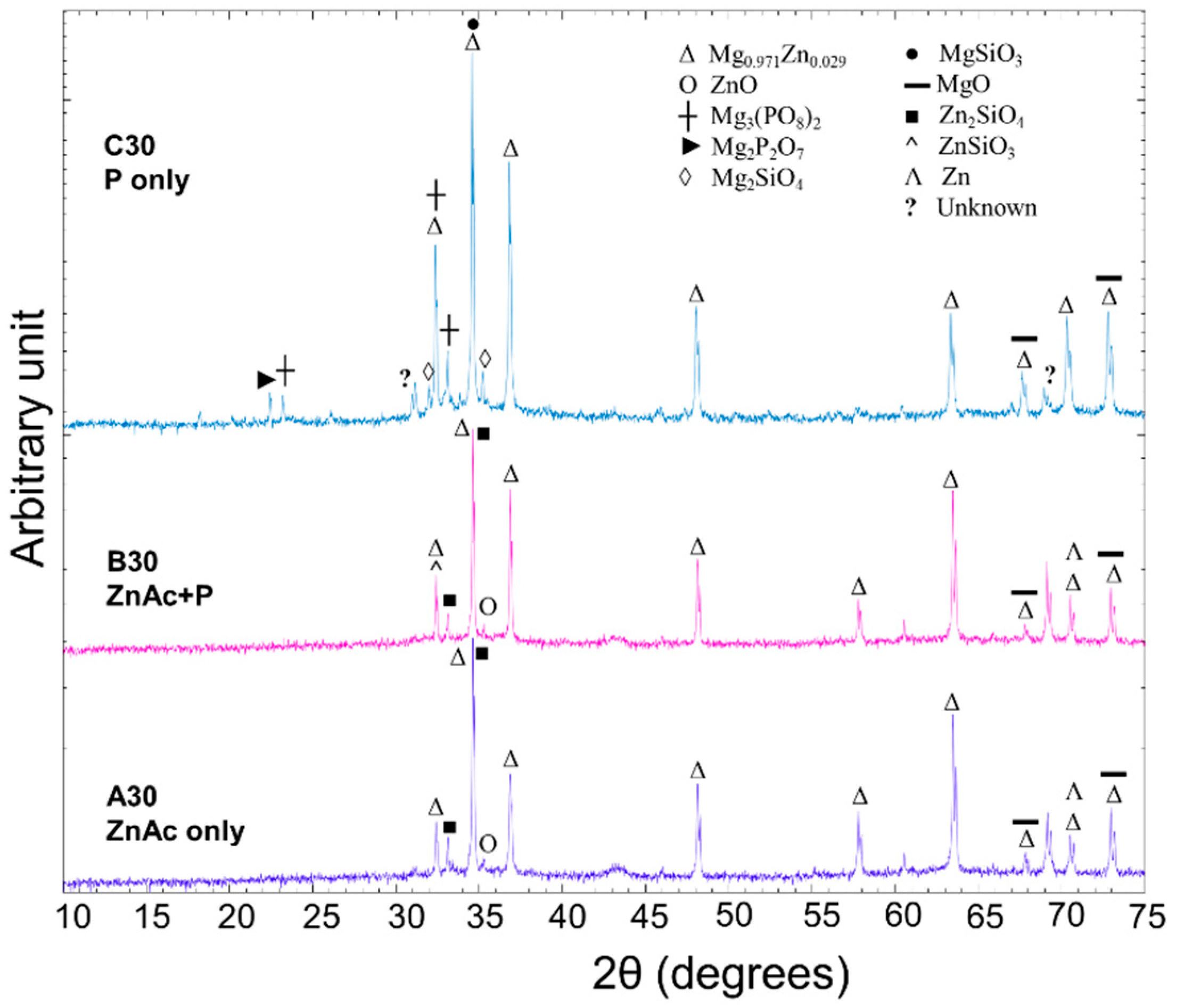
3.2. XRD Analysis
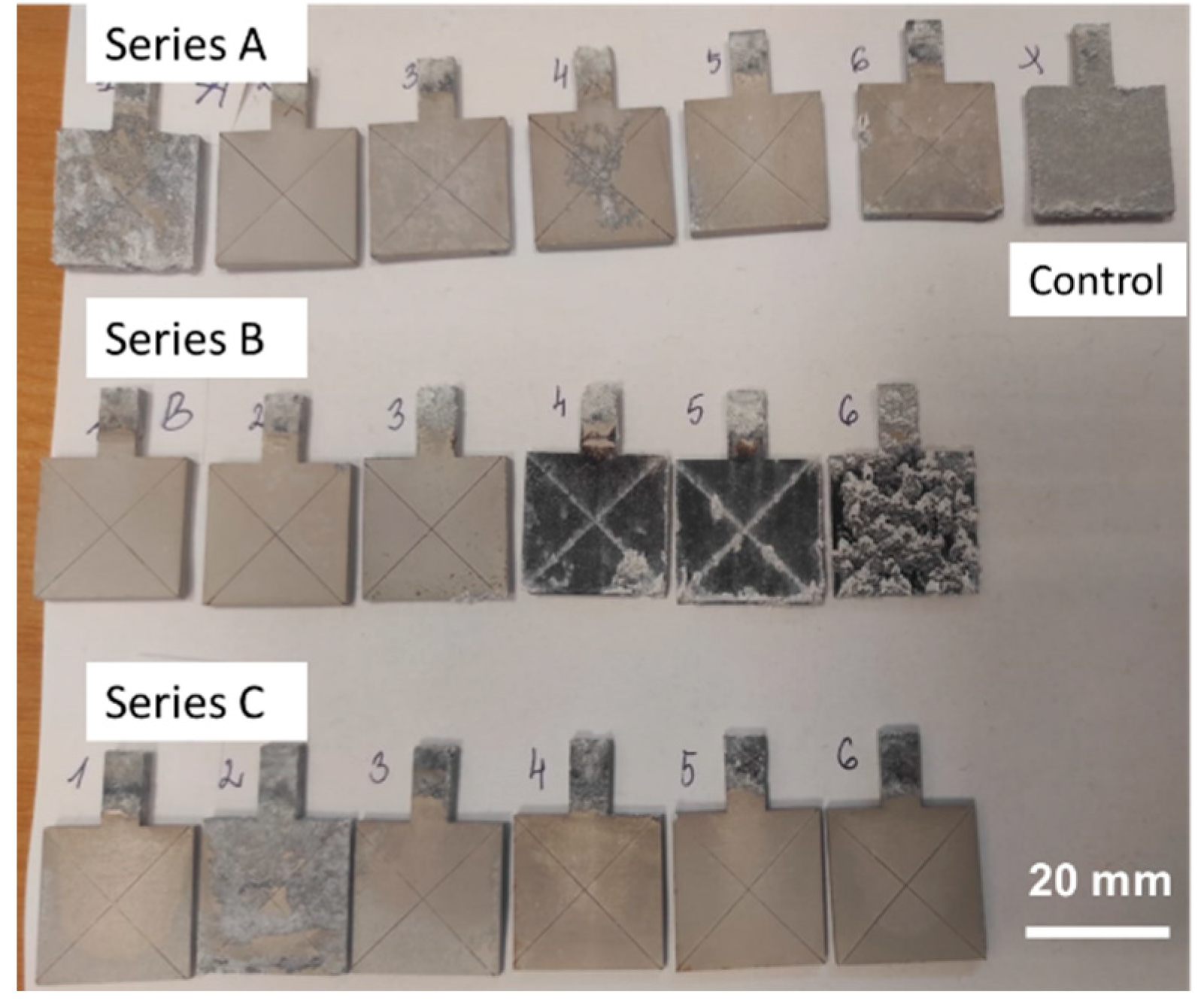
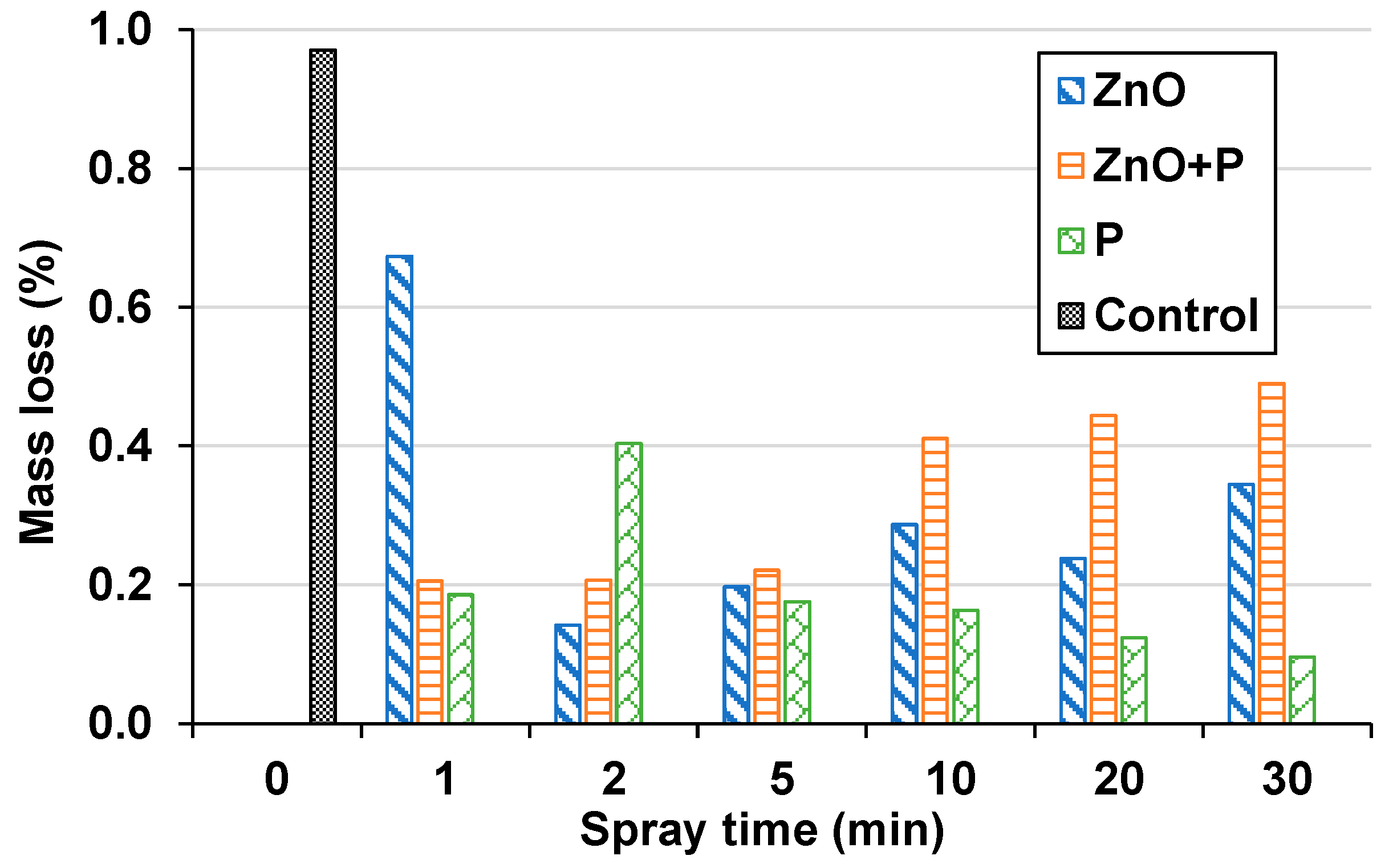
3.3. Immersion Gravimetric Testing
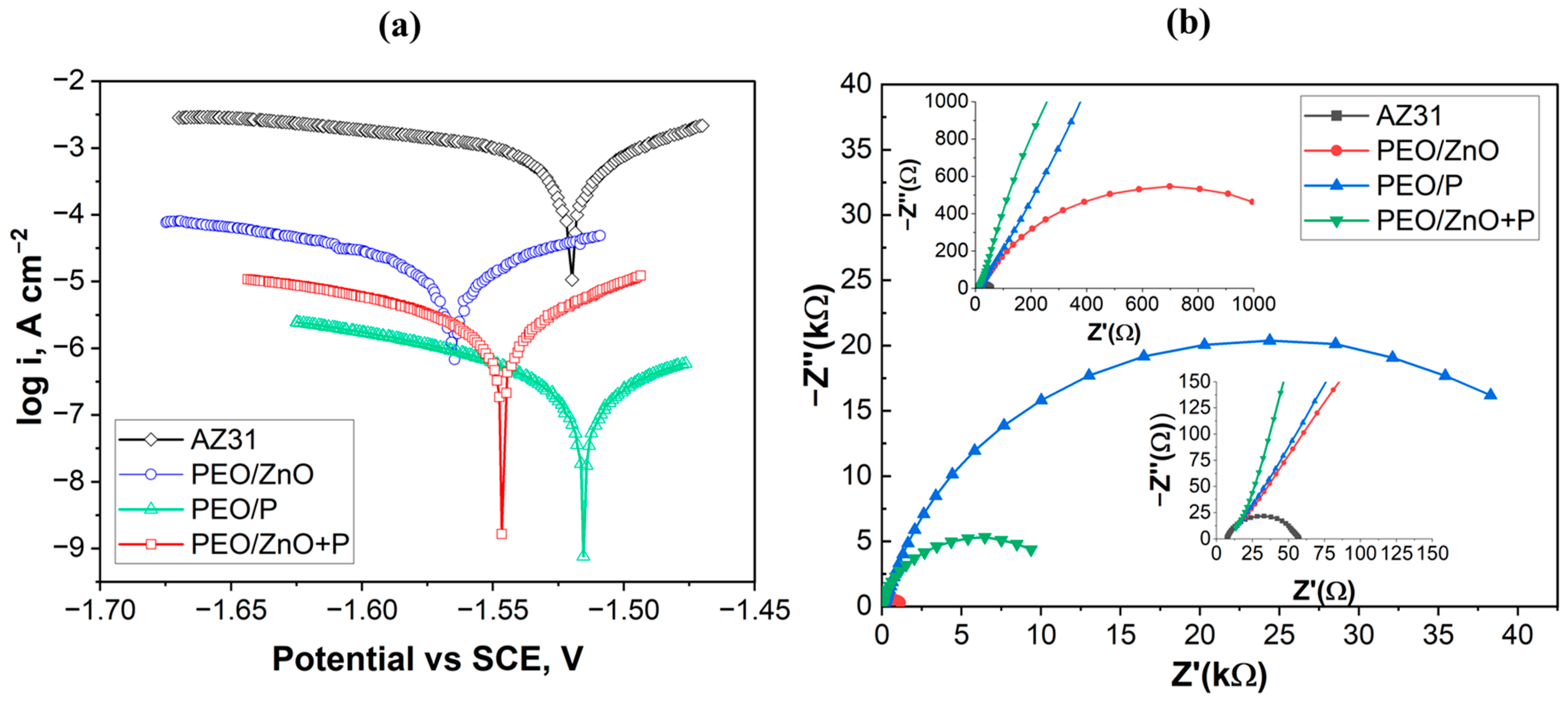
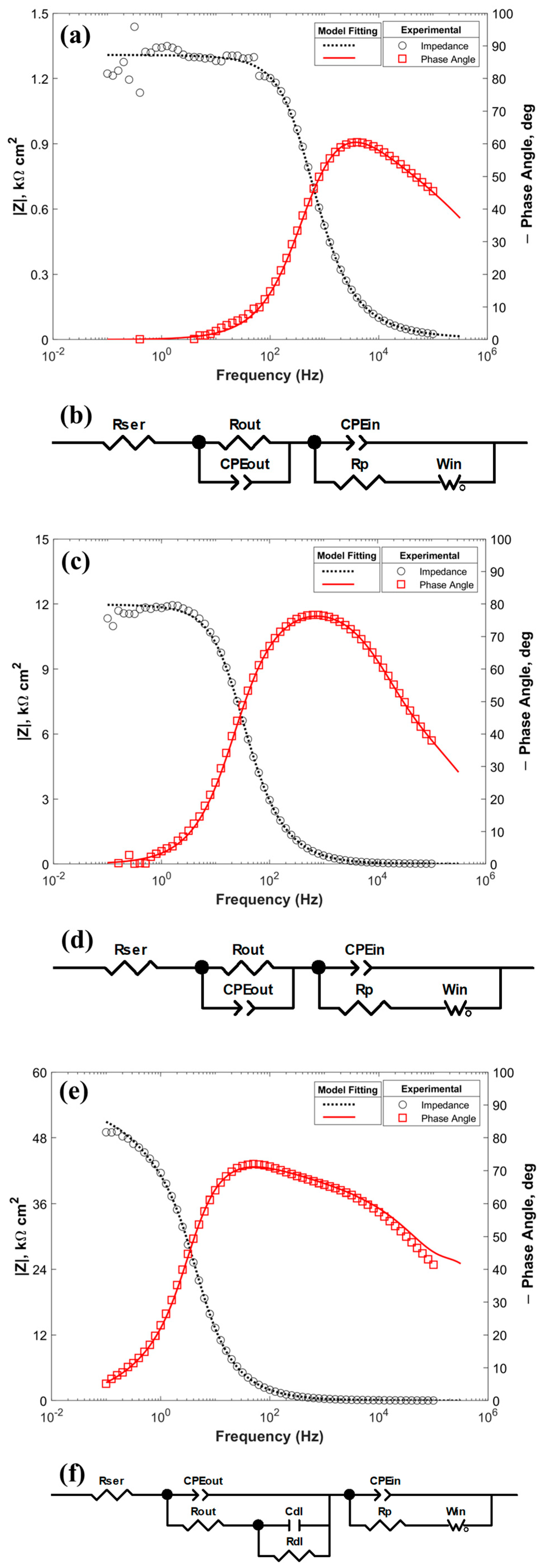
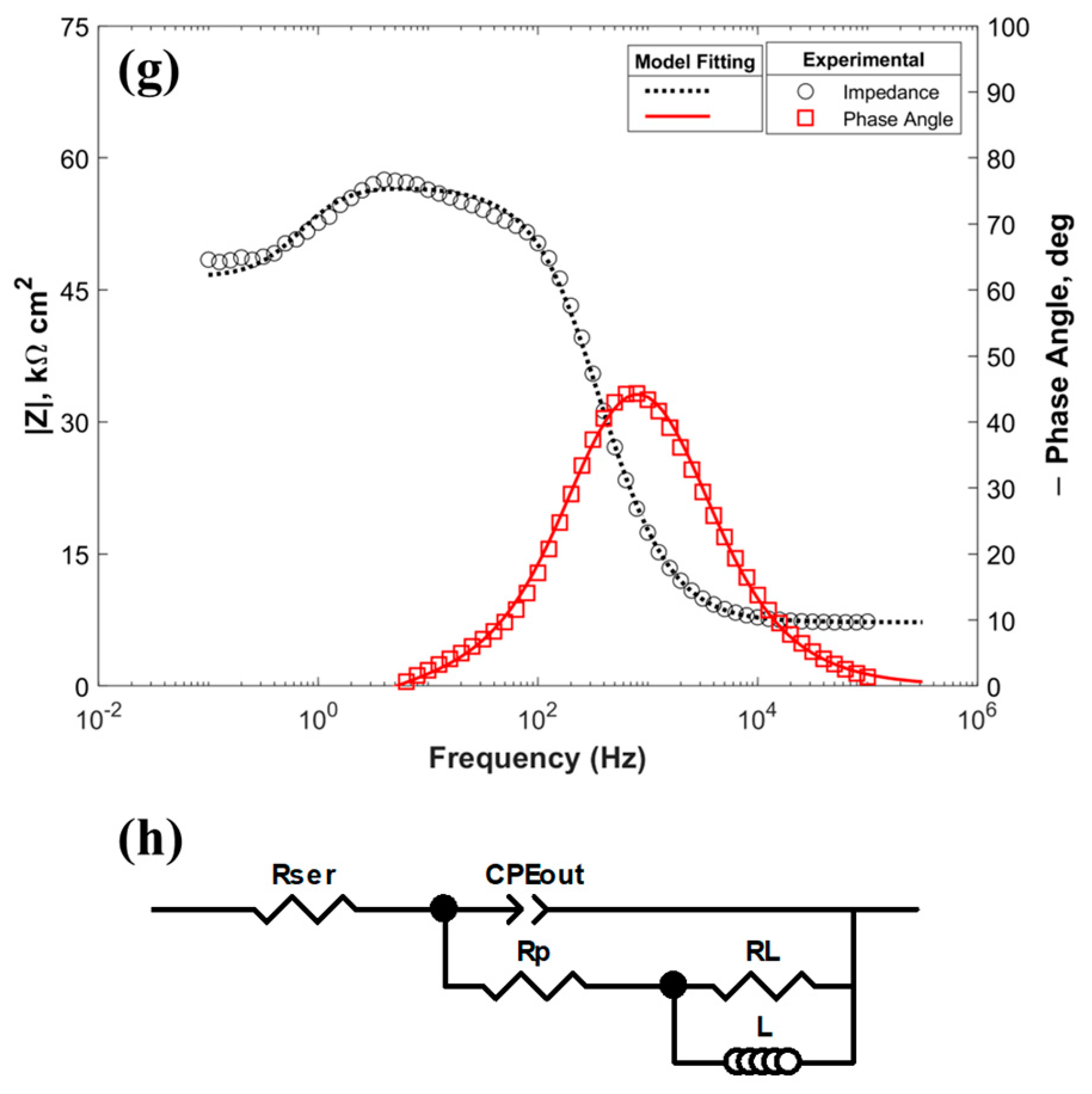
3.4. Electrochemical Corrosion Testing
3.5. EDS Element Analysis
4. Conclusions
Author Contributions
Funding
Institutional Review Board Statement
Informed Consent Statement
Data Availability Statement
Acknowledgments
Conflicts of Interest
References
- Xu, W.; Birbilis, N.; Sha, G.; Wang, Y.; Daniels, J.E.; Xiao, Y.; Ferry, M. A high-specific-strength and corrosion-resistant magnesium alloy. Nat. Mater. 2015, 14, 1229–1235. [Google Scholar] [CrossRef] [PubMed]
- Ghassemieh, E. Materials in Automotive Application, State of the Art and Prospects. In New Trends and Developments in Automotive Industry; IntechOpen: London, UK, 2011. [Google Scholar]
- Kleinbaum, S. Magnesium for Automotive Lightweighting: Status and Challenges. In Magnesium Technology; Springer International Publishing: Cham, Seirzerland, 2019. [Google Scholar]
- Jamali, S.S.; Moulton, S.E.; Tallman, D.E.; Zhao, Y.; Weber, J.; Wallace, G.G. Self-healing characteristic of praseodymium conversion coating on AZNd Mg alloy studied by scanning electrochemical microscopy. Electrochem. Commun. 2017, 76, 6–9. [Google Scholar] [CrossRef]
- Johari, N.A.; Alias, J.; Zanurin, A.; Mohamed, N.S.; Alang, N.A.; Zain, M.Z.M. Anti-corrosive coatings of magnesium: A review. Mater. Today Proc. 2022, 48, 1842–1848. [Google Scholar] [CrossRef]
- Yang, K.H.; Ger, M.D.; Hwu, W.H.; Sung, Y.; Liu, Y.C. Study of vanadium-based chemical conversion coating on the corrosion resistance of magnesium alloy. Mater. Chem. Phys. 2007, 101, 480–485. [Google Scholar] [CrossRef]
- Heydarian, A.; Atapour, M.; Hakimizad, A.; Raeissi, K. The effects of anodic amplitude and waveform of applied voltage on characterization and corrosion performance of the coatings grown by plasma electrolytic oxidation on AZ91 Mg alloy from an aluminate bath. Surf. Coat. Technol. 2020, 383, 125235. [Google Scholar] [CrossRef]
- Zehra, T.; Fattah-alhosseini, A.; Kaseem, M. Surface properties of plasma electrolytic oxidation coating modified by polymeric materials: A review. Prog. Org. Coat. 2022, 171, 107053. [Google Scholar] [CrossRef]
- Mashtalyar, D.; Imshinetsky, I.; Sinebryukhov, S.; Gnedenkov, S. Characterization of PEO-Coatings on the MA8 Magnesium Alloy Formed in Electrolyte Containing ZrO2/SiO2 Nanoparticles. Mater. Today Proc. 2019, 11, 134–138. [Google Scholar] [CrossRef]
- Toorani, M.; Aliofkhazraei, M.; Sabour Rouhaghdam, A. Microstructural, protective, inhibitory and semiconducting properties of PEO coatings containing CeO2 nanoparticles formed on AZ31 Mg alloy. Surf. Coat. Technol. 2018, 352, 561–580. [Google Scholar] [CrossRef]
- Wang, S.; Xia, Y.; Liu, L.; Si, N. Preparation and performance of MAO coatings obtained on AZ91D Mg alloy under unipolar and bipolar modes in a novel dual electrolyte. Ceram. Int. 2014, 40, 93–99. [Google Scholar] [CrossRef]
- Zhang, D.; Peng, F.; Qiu, J.; Tan, J.; Zhang, X.; Chen, S.; Qian, S.; Liu, X. Regulating corrosion reactions to enhance the anti-corrosion and self-healing abilities of PEO coating on magnesium. Corros. Sci. 2021, 192, 109840. [Google Scholar] [CrossRef]
- Mashtalyar, D.; Nadaraia, K.; Sinebryukhov, S.; Gnedenkov, S. Polymer-Containing Layers Formed by PEO and Spray-Coating Method. Mater. Today Proc. 2019, 11, 150–154. [Google Scholar] [CrossRef]
- Bakhsheshi-Rad, H.R.; Hamzah, E.; Daroonparvar, M.; Abdul Kadir, M.R.; Kasiri-Asgarani, M.; Staiger, M.P. Enhancement of corrosion resistance and mechanical properties of Mg–1.2Ca–2Bi via a hybrid silicon-biopolymer coating system. Surf. Coat. Technol. 2016, 301, 133–139. [Google Scholar] [CrossRef]
- Wierzbicka, E.; Vaghefinazari, B.; Lamaka, S.V.; Zheludkevich, M.L.; Mohedano, M.; Moreno, L.; Visser, P.; Rodriguez, A.; Velasco, J.; Arrabal, R.; et al. Flash-PEO as an alternative to chromate conversion coatings for corrosion protection of Mg alloy. Corros. Sci. 2021, 180, 109189. [Google Scholar] [CrossRef]
- Yuan, J.; Yuan, R.; Wang, J.; Li, Q.; Xing, X.; Liu, X.; Hu, W. Fabrication and corrosion resistance of phosphate/ZnO multilayer protective coating on magnesium alloy. Surf. Coat. Technol. 2018, 352, 74–83. [Google Scholar] [CrossRef]
- Bordbar-Khiabani, A.; Yarmand, B.; Mozafari, M. Enhanced corrosion resistance and in-vitro biodegradation of plasma electrolytic oxidation coatings prepared on AZ91 Mg alloy using ZnO nanoparticles-incorporated electrolyte. Surf. Coat. Technol. 2019, 360, 153–171. [Google Scholar] [CrossRef]
- Bordbar-Khiabani, A.; Yarmand, B.; Mozafari, M. Effect of ZnO pore-sealing layer on anti-corrosion and in-vitro bioactivity behavior of plasma electrolytic oxidized AZ91 magnesium alloy. Mater. Lett. 2020, 258, 126779. [Google Scholar] [CrossRef]
- Roknian, M.; Fattah-alhosseini, A.; Gashti, S.O.; Keshavarz, M.K. Study of the effect of ZnO nanoparticles addition to PEO coatings on pure titanium substrate: Microstructural analysis, antibacterial effect and corrosion behavior of coatings in Ringer’s physiological solution. J. Alloys Compd. 2018, 740, 330–345. [Google Scholar] [CrossRef]
- Qian, K.; Dong, Q.; Zhang, Y.; Shao, Y.; Cheng, Z.; Xia, D.; Ju, J.; Xue, F.; Chu, C.; Bai, J. Corrosion prevention for PEO-coated Mg by phosphate-based sealing treatment with added cation. Appl. Surf. Sci. 2023, 629, 157351. [Google Scholar] [CrossRef]
- Qian, K.; Zhang, Y.; Dong, Q.; Shao, Y.; Cheng, Z.; Ju, J.; Xue, F.; Chu, C.; Xia, D.; Bai, J. Enhancement of corrosion resistance and antibacterial properties of PEO coated AZ91D Mg alloy by copper- and phosphate-based sealing treatment. Corros. Sci. 2023, 219, 111218. [Google Scholar] [CrossRef]
- Phuong, N.V.; Fazal, B.R.; Moon, S. Cerium- and phosphate-based sealing treatments of PEO coated AZ31 Mg alloy. Surf. Coat. Technol. 2017, 309, 86–95. [Google Scholar] [CrossRef]
- Chamberlin, R.R.; Skarman, J.S. Chemical Spray Deposition Process for Inorganic Films. J. Electrochem. Soc. 1966, 113, 86. [Google Scholar] [CrossRef]
- Inada, M.; Hojo, J. Synthesis of hollow ceria-zirconia solid solution particles by spray pyrolysis with organic ligands and its oxygen storage capacity. Adv. Powder Technol. 2022, 33, 103647. [Google Scholar] [CrossRef]
- Nouri, Y.; Hartiti, B.; Labrim, H.; Ziti, A.; Belfhaili, A.; Batan, A.; Fadili, S.; Tahri, M.; Thévenin, P. Synthesis of tin monosulfide SnS thin films via spray pyrolysis method based on Taguchi design for solar absorber. Opt. Mater. 2022, 131, 112669. [Google Scholar] [CrossRef]
- Hasegawa, H.; Ueda, T.; Yokomori, T. Y2Si2O7:Eu/SiO2 core shell phosphor particles prepared by flame spray pyrolysis. Proc. Combust. Inst. 2013, 34, 2155–2162. [Google Scholar] [CrossRef]
- Ukoba, K.O.; Eloka-Eboka, A.C.; Inambao, F.L. Review of nanostructured NiO thin film deposition using the spray pyrolysis technique. Renew. Sustain. Energy Rev. 2018, 82, 2900–2915. [Google Scholar] [CrossRef]
- Hajjar, Z.; Kazemeini, M.; Rashidi, A.; Soltanali, S.; Bahadoran, F. Naphtha HDS over Co-Mo/Graphene catalyst synthesized through the spray pyrolysis technique. J. Anal. Appl. Pyrolysis 2017, 123, 144–151. [Google Scholar] [CrossRef]
- Annu, A.; Bhattacharya, B.; Singh, P.K.; Shukla, P.K.; Rhee, H.-W. Carbon nanotube using spray pyrolysis: Recent scenario. J. Alloys Compd. 2017, 691, 970–982. [Google Scholar] [CrossRef]
- Vo, T.K.; Quang, D.T.; Kim, J. Spray pyrolysis-derived MoO3@Al2O3@TiO2 core-shell structures with enhanced hydrodeoxygenation performance. Catal. Commun. 2022, 169, 106478. [Google Scholar] [CrossRef]
- dos Santos-Gómez, L.; Zamudio-García, J.; Porras-Vázquez, J.M.; Losilla, E.R.; Marrero-López, D. Recent progress in nanostructured electrodes for solid oxide fuel cells deposited by spray pyrolysis. J. Power Sources 2021, 507, 230277. [Google Scholar] [CrossRef]
- Drunka, R.; Iesalniece, P.; Savkovs, K.; Krumina, A. Plasma electrolytic oxidation of AZ31 Mg alloy in bipolar pulse mode and influence of corrosion to surface morphology of obtained coatings. Mat. Sc. (MEDŽIAGOTYRA) early Access. 2022. [Google Scholar] [CrossRef]
- Thirumalaikumarasamy, D.; Shanmugam, K.; Balasubramanian, V. Influence of chloride ion concentration on immersion corrosion behaviour of plasma sprayed alumina coatings on AZ31B magnesium alloy. J. Magnes. Alloys 2014, 2, 325–334. [Google Scholar] [CrossRef]
- Yang, P.; Ye, S.; Feng, B.; Liu, J.; Huang, S.; Liu, G.; Zhang, W.; Tang, W.; Zhu, S.; Zhang, S. Microgalvanic Corrosion of Mg-Ca and Mg-Al-Ca Alloys in NaCl and Na2SO4 Solutions. Materials 2021, 14, 7140. [Google Scholar] [CrossRef] [PubMed]
- Pinela, V.M.; de Oliveira, L.A.; de Oliveira, M.C.L.; Antunes, R.A. Study of the Corrosion Process of AZ91D Magnesium Alloy during the First Hours of Immersion in 3.5 wt.% NaCl Solution. Int. J. Corros. 2018, 2018, 8785154. [Google Scholar] [CrossRef]
- Singh, A.K.; Drunka, R.; Smits, K.; Vanags, M.; Iesalnieks, M.; Joksa, A.A.; Blumbergs, I.; Steins, I. Nanomechanical and Electrochemical Corrosion Testing of Nanocomposite Coating Obtained on AZ31 via Plasma Electrolytic Oxidation Containing TiN and SiC Nanoparticles. Crystals 2023, 13, 508. [Google Scholar] [CrossRef]
- Xu, C.; Gao, W. Pilling-Bedworth ratio for oxidation of alloys. Mater. Res. Innov. 2000, 3, 231–235. [Google Scholar] [CrossRef]
- Marzbanrad, B.; Razmpoosh, M.H.; Toyserkani, E.; Jahed, H. Role of heat balance on the microstructure evolution of cold spray coated AZ31B with AA7075. J. Magnes. Alloys 2021, 9, 1458–1469. [Google Scholar] [CrossRef]
- Seyfi, M.; Fattah-alhosseini, A.; Pajohi-Alamoti, M.; Nikoomanzari, E. Effect of ZnO nanoparticles addition to PEO coatings on AZ31B Mg alloy: Antibacterial effect and corrosion behavior of coatings in Ringer’s physiological solution. J. Asian Ceram. Soc. 2021, 9, 1114–1127. [Google Scholar] [CrossRef]
- Das, S.; Srivasatava, V.C. Synthesis and Characterization of ZnO–MgO Nanocomposite by Co-precipitation Method. Smart Sci. 2016, 4, 190–195. [Google Scholar] [CrossRef]
- da Silva, R.M.P.; Milagre, M.X.; Izquierdo, J.; Betancor-Abreu, A.M.; de Oliveira, L.A.; Araujo, J.V.d.S.; Antunes, R.A.; Souto, R.M.; Costa, I. Surface finishing effects on the corrosion behavior and electrochemical activity of 2098-T351 aluminum alloy investigated using scanning microelectrochemical techniques. Mater. Charact. 2022, 191, 112130. [Google Scholar] [CrossRef]
- Lehraki, N.; Aida, M.S.; Abed, S.; Attaf, N.; Attaf, A.; Poulain, M. ZnO thin films deposition by spray pyrolysis: Influence of precursor solution properties. Curr. Appl. Phys. 2012, 12, 1283–1287. [Google Scholar] [CrossRef]
- Saidi, R.; Raeissi, K.; Ashrafizadeh, F.; Kharaziha, M. The effect of zinc oxide coating morphology on corrosion performance of Ti-6Al-4 V alloys. J. Alloys Compd. 2021, 883, 160771. [Google Scholar] [CrossRef]
- Perumal, P.; Ramanathan, K.; Ganesan, L.; Subramanian, B.; Ganesh, V.; Stalin, B. Investigation of TiN coating uniformity and its corrosion behaviour using image process. Mater. Res. Express 2019, 6, 046411. [Google Scholar] [CrossRef]
- Pawlig, O.; Trettin, R. Synthesis and characterization of α-hopeite, Zn3(PO4)2·4H2O. Mater. Res. Bull. 1999, 34, 1959–1966. [Google Scholar] [CrossRef]
- Zhang, Y.; Chen, F.; Zhang, Y.; Du, C. Influence of graphene oxide additive on the tribological and electrochemical corrosion properties of a PEO coating prepared on AZ31 magnesium alloy. Tribol. Int. 2020, 146, 106135. [Google Scholar] [CrossRef]
- Lazanas, A.C.; Prodromidis, M.I. Electrochemical Impedance Spectroscopy–A Tutorial. ACS Meas. Sci. Au 2023, 3, 162–193. [Google Scholar] [CrossRef]
- Keyvani, A.; Zamani, M.; Bahamirian, M.; Nikoomanzari, E.; Fattah-alhosseini, A.; Sina, H. Role of incorporation of ZnO nanoparticles on corrosion behavior of ceramic coatings developed on AZ31 magnesium alloy by plasma electrolytic oxidation technique. Surf. Interfaces 2021, 22, 100728. [Google Scholar] [CrossRef]
- Lou, G.; Jia, P.; Teng, X.; Zhang, J.; Ye, Z.; Wu, H.; Leng, J.; Zuo, M. Nano ZnO-assisted formation of zinc phosphate conversion coating for improving corrosion protection of AZ91D magnesium alloy. Mater. Res. Express 2019, 6, 086405. [Google Scholar] [CrossRef]


| Coating Material | Spray Time (Minutes) | |||||
|---|---|---|---|---|---|---|
| 1 | 2 | 5 | 10 | 20 | 30 | |
| ZnO | A1 | A2 | A5 | A10 | A20 | A30 |
| ZnO+P | B1 | B2 | B5 | B10 | B20 | B30 |
| P | C1 | C2 | C5 | C10 | C20 | C30 |
| Coating Type | Sample ID | Polarization Resistance Method | ||||
|---|---|---|---|---|---|---|
| Corrosion Rate (mm/yr) | Icorr (µA/cm2) | Icorr (µA) | Polarization Resistance (kΩ) | Ecorr (V) | ||
| AZ31 | Control | 50.36 | 1108.8 | 1948.5 | 0.0272 | −1.52 |
| ZnO | A2 | 58.00 × 10⁻² | 12.7 | 22.4 | 1.2 | −1.56 |
| ZnO+P | B2 | 9.71 × 10⁻² | 2.12 | 3.76 | 6.9 | −1.55 |
| P | C30 | 1.11 × 10⁻² | 0.24 | 0.43 | 60.7 | −1.52 |
| Coating | Rser (Ω cm2) | Rout (Ω cm2) | CPEout | CPEin | Rp (kΩ cm2) | Warburg Element (W) | ||||
|---|---|---|---|---|---|---|---|---|---|---|
| μF cm−2 sn−1 | n | (μF cm−2 sn−1) | n | W0 (Ω−1 cm2 s−1/2) | B (×103) | |||||
| PEO/ZnO | 4.85 | 85.9 | 58.6 | 0.51 | 0.73 | 0.89 | 1.28 | 125.66 | 0.86 | |
| PEO/ZnO+P | 5.97 | 17.8 | 30.8 | 0.60 | 0.96 | 0.90 | 11.95 | 47.14 | 1.88 | |
| Rser (Ω cm2) | Rout (Ω cm2) | CPEout | Cdl (μF cm−2) | Rdl (Ω cm2) | Cin (μF cm−2) | Rp (kΩ cm2) | Warburg Element (W) | |||
| μF cm−2 sn−1 | n | W0 (Ω−1 cm2 s−1/2) | B (×103) | |||||||
| PEO/P | 5.28 | 26.5 | 11.5 | 0.67 | 0.215 | 3.38 | 1.79 | 27.51 | 14.4 | 17.5 |
| Rser (Ω cm2) | Rp (Ω cm2) | CPEout | RL (Ω cm2) | L (H cm2) | ||||||
| μF cm−2 sn−1 | n | |||||||||
| AZ31 | 7.23 | 39.3 | 25.75 | 0.90 | 10.39 | 2.29 | ||||
Disclaimer/Publisher’s Note: The statements, opinions and data contained in all publications are solely those of the individual author(s) and contributor(s) and not of MDPI and/or the editor(s). MDPI and/or the editor(s) disclaim responsibility for any injury to people or property resulting from any ideas, methods, instructions or products referred to in the content. |
© 2023 by the authors. Licensee MDPI, Basel, Switzerland. This article is an open access article distributed under the terms and conditions of the Creative Commons Attribution (CC BY) license (https://creativecommons.org/licenses/by/4.0/).
Share and Cite
Singh, A.K.; Drunka, R.; Iesalniece, P.; Blumbergs, I.; Steins, I.; Eiduks, T.-V.; Iesalnieks, M.; Savkovs, K. Combined PEO and Spray Pyrolysis Coatings of Phosphate and ZnO for Enhancing Corrosion Resistance in AZ31 Mg Alloy. Surfaces 2023, 6, 364-379. https://doi.org/10.3390/surfaces6040026
Singh AK, Drunka R, Iesalniece P, Blumbergs I, Steins I, Eiduks T-V, Iesalnieks M, Savkovs K. Combined PEO and Spray Pyrolysis Coatings of Phosphate and ZnO for Enhancing Corrosion Resistance in AZ31 Mg Alloy. Surfaces. 2023; 6(4):364-379. https://doi.org/10.3390/surfaces6040026
Chicago/Turabian StyleSingh, Ashish Kumar, Reinis Drunka, Paula Iesalniece, Ilmars Blumbergs, Ints Steins, Toms-Valdemars Eiduks, Mairis Iesalnieks, and Konstantins Savkovs. 2023. "Combined PEO and Spray Pyrolysis Coatings of Phosphate and ZnO for Enhancing Corrosion Resistance in AZ31 Mg Alloy" Surfaces 6, no. 4: 364-379. https://doi.org/10.3390/surfaces6040026