
Asynchronous Stabilization for Two Classes of Stochastic Switching Systems with Applications on Servo Motors

Abstract
:1. Introduction
- 1.
- New stability criteria are proposed for the considered stochastic switching systems, which can well handle the asynchronous phenomenon. It is noted that the Lyapunov function is allowed to increase during some unmatched interval to reduce the conservatism of controller design;
- 2.
- Numerically testable asynchronous controller design methods are presented for the dual switching system. The proposed method is suitable for the situation where the asynchronous phenomenon can come from both inaccurate mode detection and time varying delay. Meanwhile, the transition probabilities are both uncertain and partly accessible;
- 3.
- Novel asynchronous controller design methods are presented for the semi-Markov jump systems. The sojourn time of the semi-Markov jump systems can have both lower and upper bounds, which could be more practical than previous scenarios.
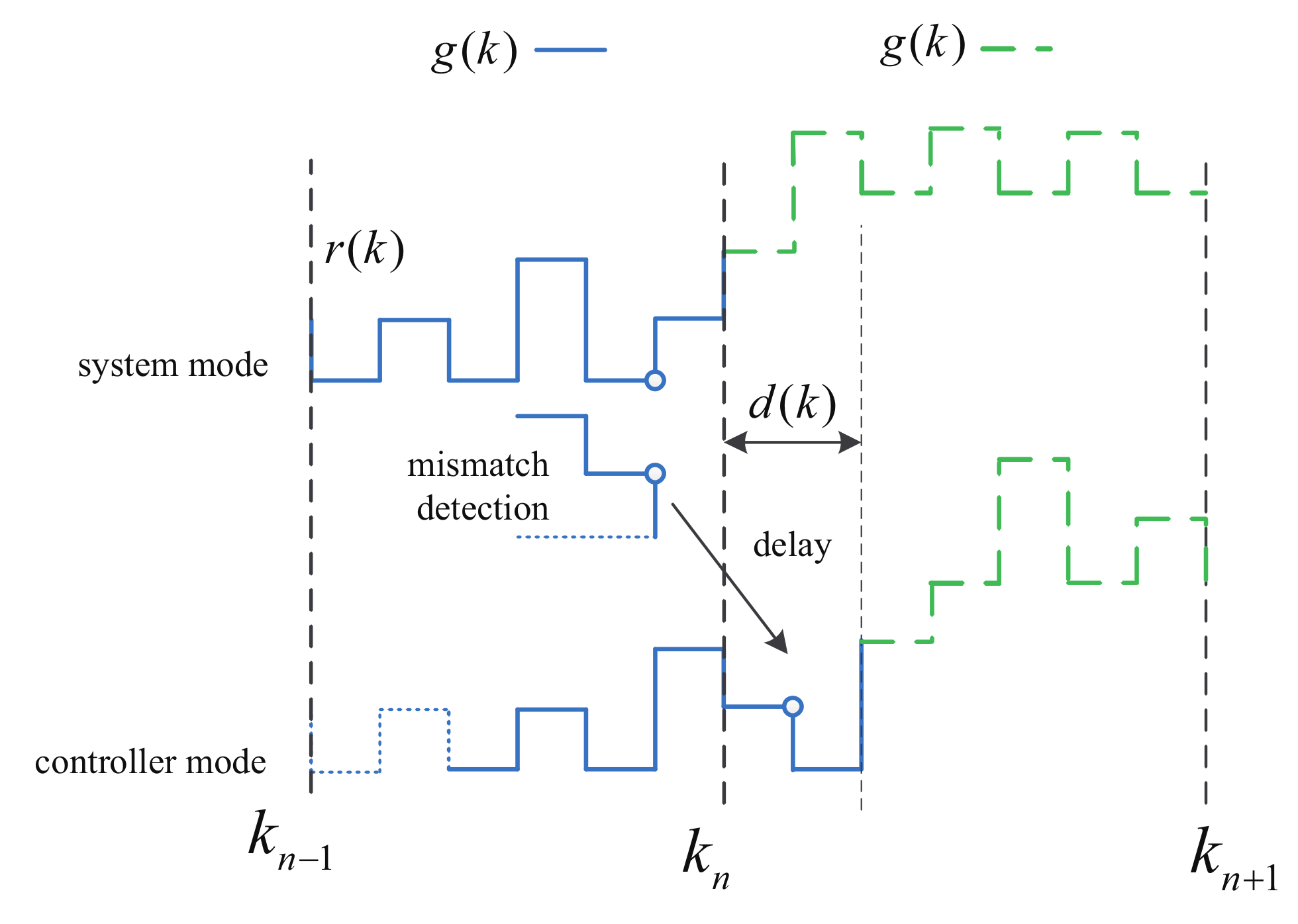
2. Problem Formulation
2.1. Problem Formulation for Dual Switching Systems
2.2. Problem Formulation for Semi-Markov Jump Systems
3. Main Results
3.1. Asynchronous Controller Design for Dual Switching Systems
3.2. Asynchronous Controller Design for Semi-Markov Systems
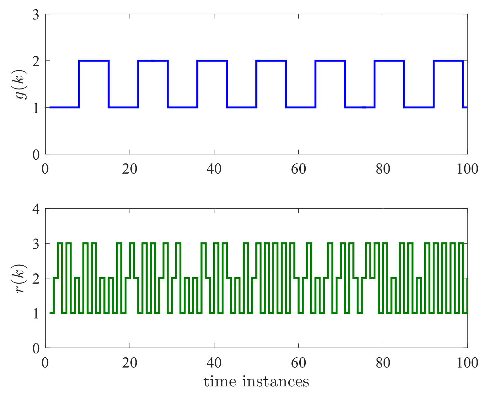
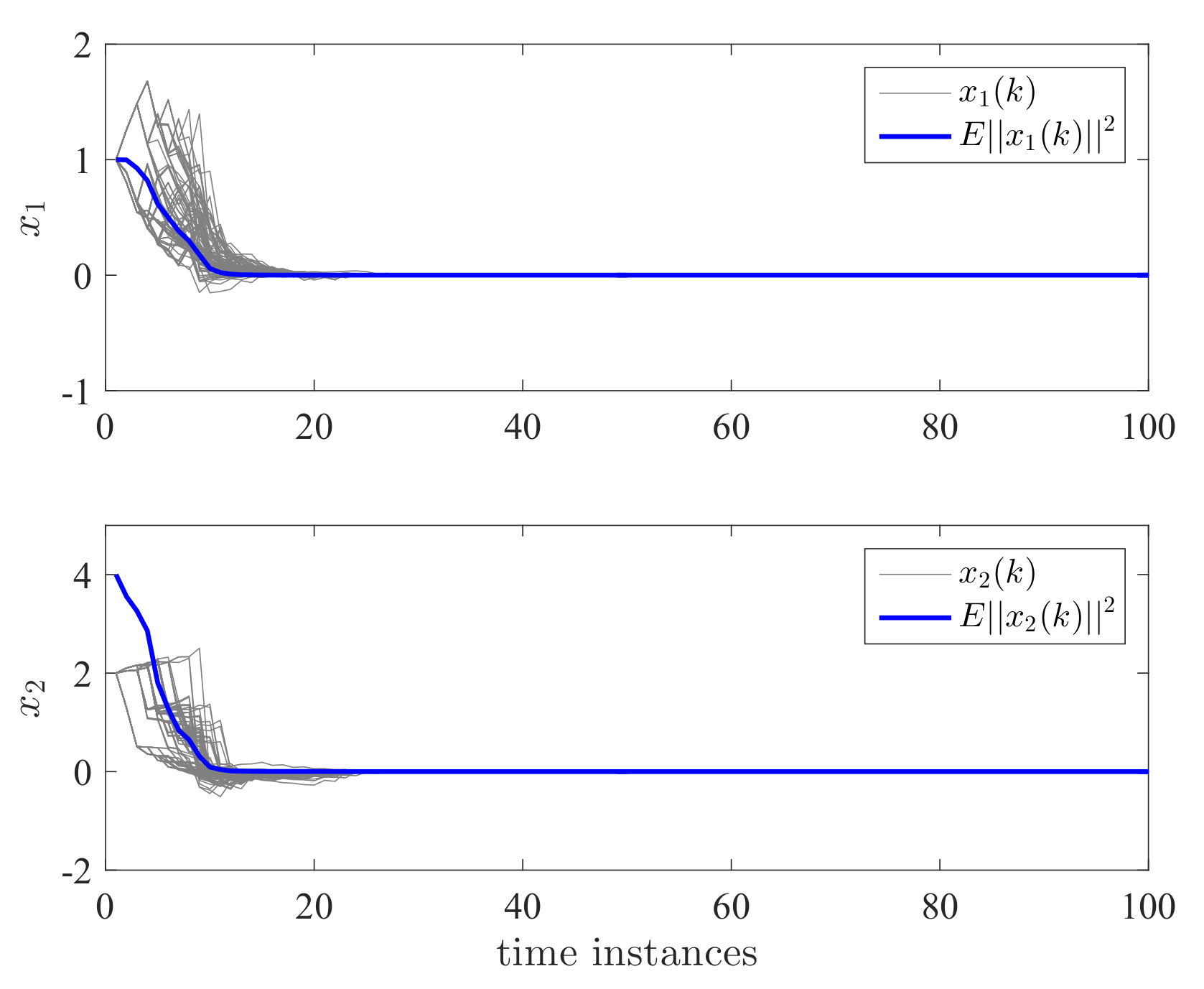
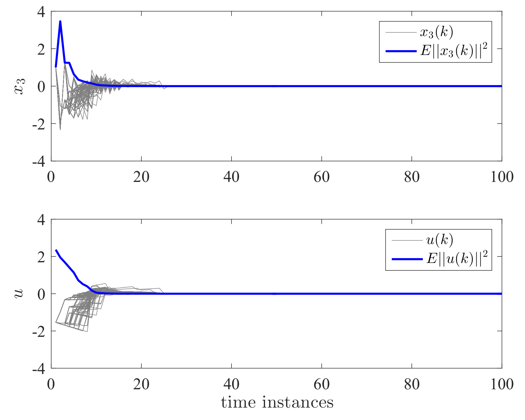
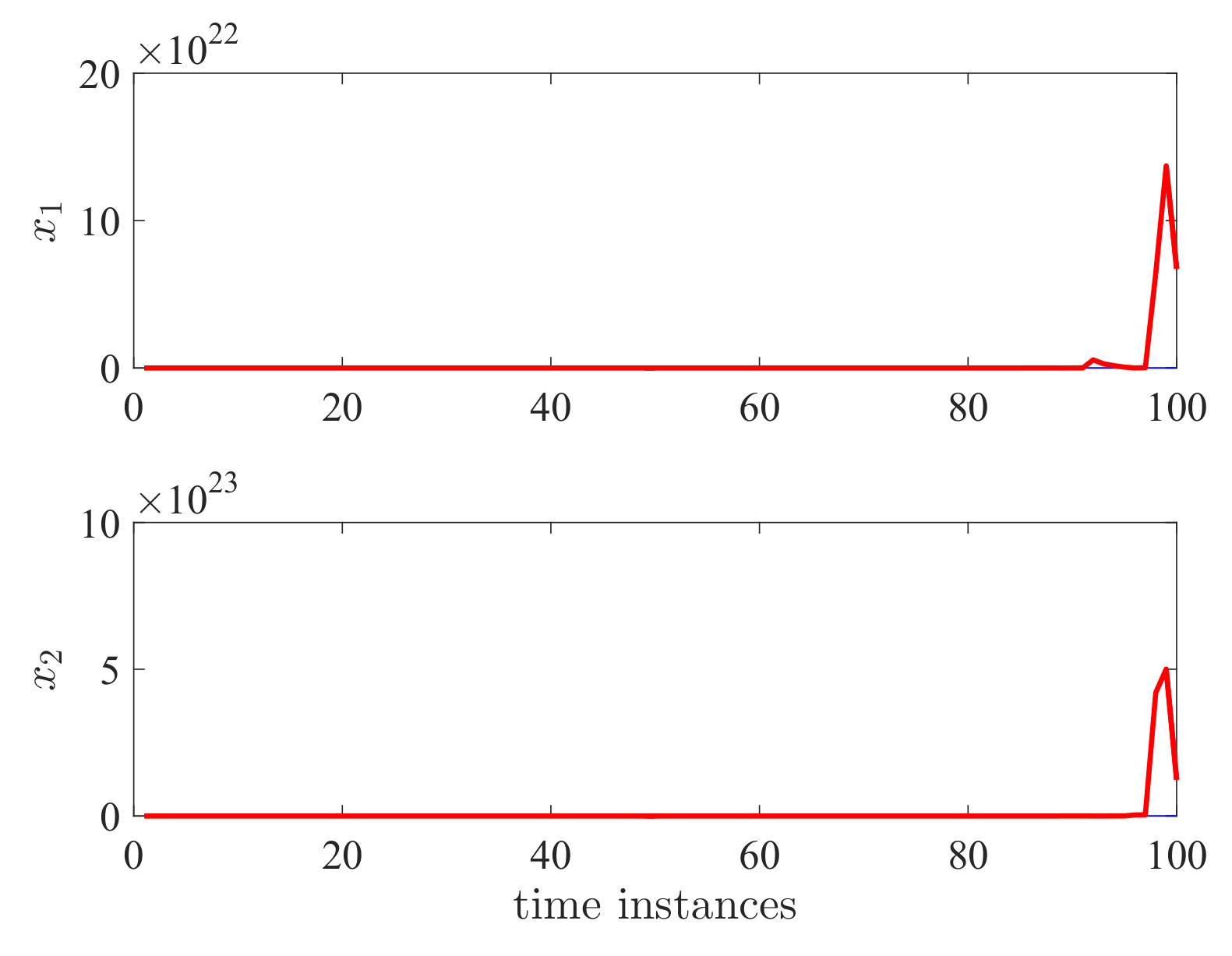
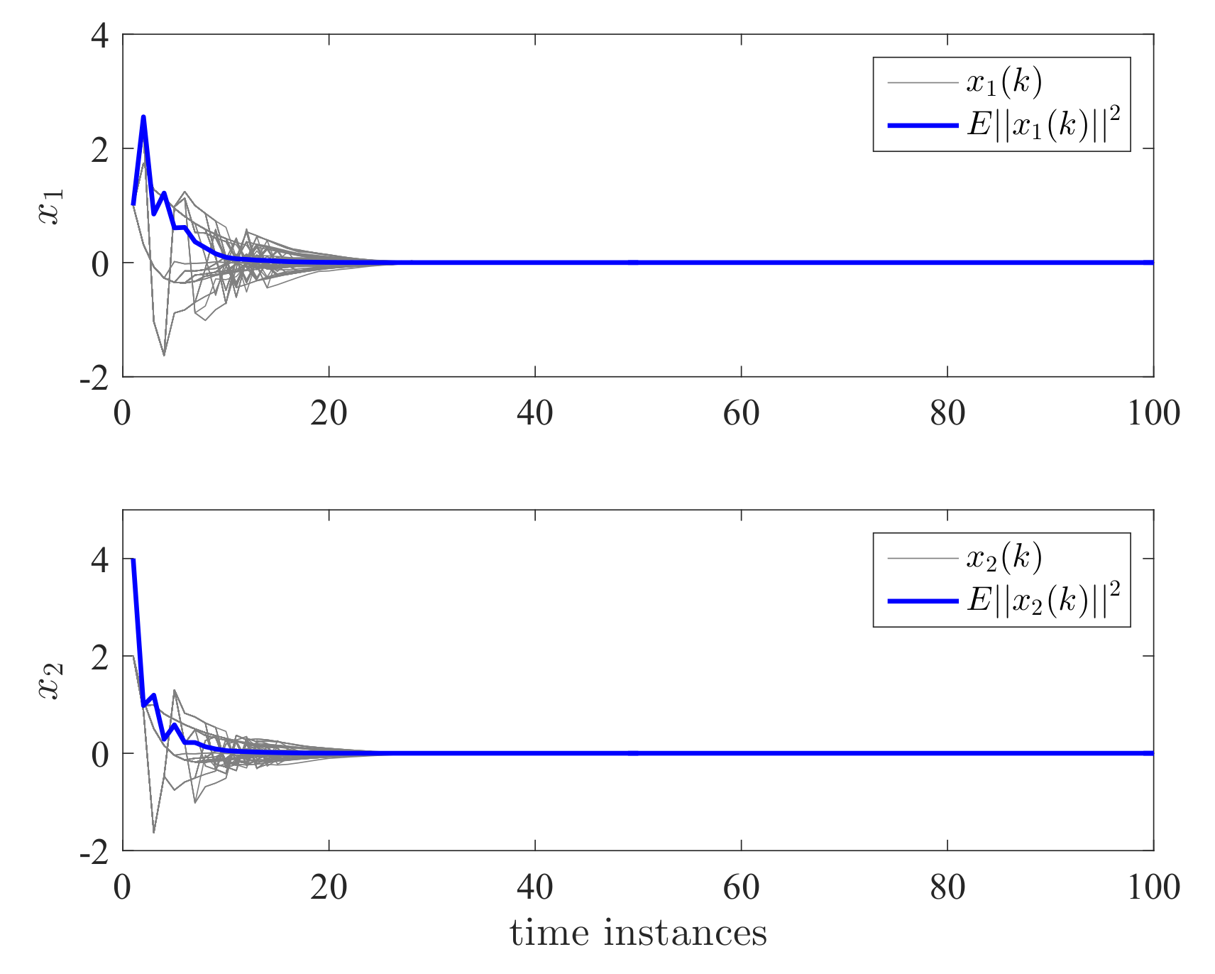
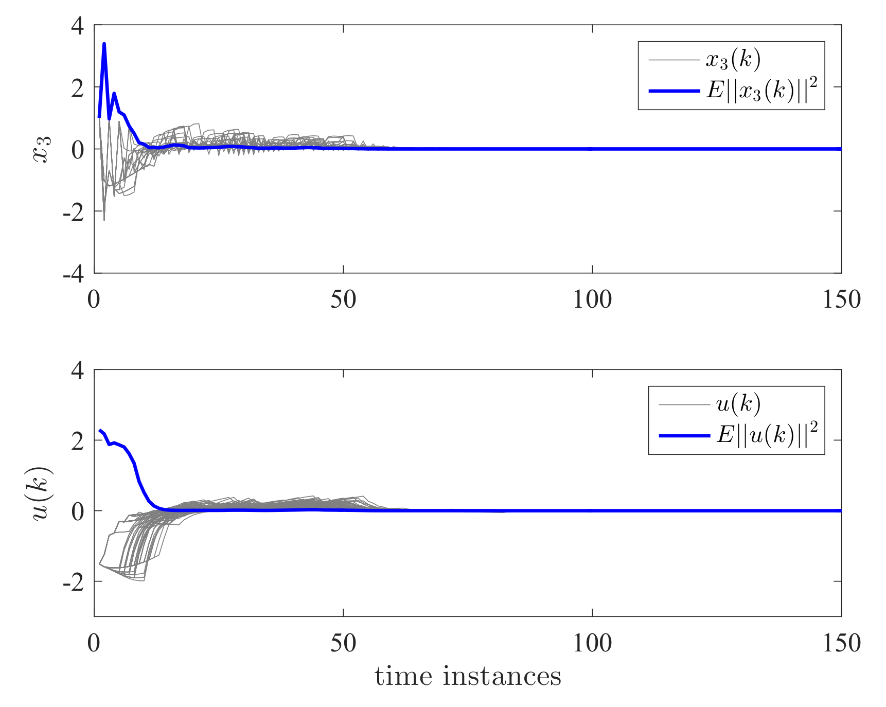
4. Examples
5. Conclusions
Author Contributions
Funding
Institutional Review Board Statement
Informed Consent Statement
Data Availability Statement
Conflicts of Interest
Appendix A
Appendix A.1. Proof of Lemma 1
Appendix A.2. Proof of Lemma 2
Appendix A.3. Proof of Theorem 1
Appendix A.4. Proof of Lemma 3
Appendix A.5. Proof of Lemma 4
Appendix A.6. Proof of Lemma 5
Appendix A.7. Proof of Theorem 2
References
- Lin, X.; Chen, C.; Qian, C. Smooth output feedback stabilization of a class of planar switched nonlinear systems under arbitrary switchings. Automatica 2017, 82, 314–318. [Google Scholar] [CrossRef]
- Li, Y.; Sui, S.; Tong, S. Adaptive fuzzy control design for stochastic nonlinear switched systems with arbitrary switchings and unmodeled dynamics. IEEE Trans. Cybern. 2017, 47, 403–414. [Google Scholar] [CrossRef] [PubMed]
- Shen, H.; Xing, M.; Xu, S.; Basin, M.; Park, J. H∞, stabilization of discrete-time nonlinear semi-Markov jump singularly perturbed systems with partially known semi-Markov kernel information. IEEE Trans. Circuits Syst. I Regul. Pap. 2021, 68, 818–828. [Google Scholar] [CrossRef]
- Shen, H.; Chen, M.; Wu, Z.; Cao, J.; Park, J. Reliable event-triggered asynchronous extended passive control for semi-Markov jump fuzzy systems and its application. IEEE Trans. Fuzzy Syst. 2020, 28, 1708–1722. [Google Scholar] [CrossRef]
- Meng, J.; Wang, S.; Li, G.; Jiang, L.; Zhang, X.; Liu, C.; Xie, Y. Iterative-learning error compensation for autonomous parking of mobile manipulator in harsh industrial environment. Robot. Comput.-Integr. Manuf. 2021, 68, 102077. [Google Scholar] [CrossRef]
- Vargas, A.; Costa, E.; Val, J. On the control of Markov jump linear systems with no mode observation: Application to a DC Motor device. Int. J. Robust Nonlinear Control. 2013, 23, 1136–1150. [Google Scholar] [CrossRef]
- Li, Y.; Tong, S. Adaptive fuzzy output-feedback stabilization control for a class of switched non-strict-feedback nonlinear systems. IEEE Trans. Cybern. 2017, 47, 1007–1016. [Google Scholar] [CrossRef]
- Zheng, S.; Shi, P.; Xie, Y.; Wang, S. Fast finite-time tracking consensus with applications on multiple servo motors. IEEE Trans. Ind. Electron. 2022. [Google Scholar] [CrossRef]
- Liu, W.; Huang, J. Cooperative adaptive output regulation for second-order nonlinear multiagent systems with jointly connected switching networks. IEEE Trans. Neural Netw. Learn. Syst. 2018, 29, 695–705. [Google Scholar] [CrossRef]
- Jiang, B.; Kao, Y.; Karimi, H.R.; Gao, C. Stability and stabilization for singular switching semi-Markovian jump systems with generally uncertain transition rates. IEEE Trans. Autom Control. 2018, 63, 3919–3926. [Google Scholar] [CrossRef]
- Ning, Z.; Zhang, L.; Lam, J. Stability and stabilization of a class of stochastic switching systems with lower bound of sojourn time. Automatica 2018, 92, 18–28. [Google Scholar] [CrossRef]
- Wang, B.; Zhu, Q. Stability analysis of semi-Markov switched stochastic systems. Automatica 2018, 94, 72–80. [Google Scholar] [CrossRef]
- Zhang, L.; Prieur, C. Stochastic stability of Markov jump hyperbolic systems with application to traffic flow control. Automatica 2017, 86, 29–37. [Google Scholar] [CrossRef]
- Sala, A.; Hernandez-Mejias, M.; Arino, C. Stable receding-horizon scenario predictive control for Markov-jump linear systems. Automatica 2017, 86, 121–128. [Google Scholar] [CrossRef]
- Todorov, M.; Fragoso, M.; Costa, O. Detector-based H∞ results for discrete-time Markov jump linear systems with partial observations. Automatica 2018, 91, 159–172. [Google Scholar] [CrossRef]
- Li, Y.; Tong, S.; Liu, L.; Feng, G. Adaptive output feedback control design with prescribed performance for switched nonlinear systems. Automatica 2017, 80, 225–231. [Google Scholar] [CrossRef]
- Yao, L.; Zhang, W. Adaptive tracking control for a class of random pure-feedback nonlinear systems with Markovian switching. Int. J. Robust Nonlinear Control. 2018, 28, 3112–3126. [Google Scholar] [CrossRef]
- Sun, Q.; Lim, C.; Shi, P.; Liu, F. Design and stability of moving horizon estimator for Markov jump linear systems. IEEE Trans. Autom. Control. 2018, 64, 1109–1124. [Google Scholar] [CrossRef]
- Liu, W. State estimation for discrete-time Markov jump linear systems with time-correlated measurement noise. Automatica 2017, 76, 266–276. [Google Scholar] [CrossRef]
- Wen, J.; Shi, P.; Li, R.; Luan, X. Distributed filtering for semi-Markov type sensor networks with hybrid sojourn-time distributions-a non-monotonic approach. IEEE Trans. Cybern. 2022. [Google Scholar] [CrossRef]
- Shi, T.; Shi, P.; Wu, Z. Dynamic event-triggered asynchronous MPC of Markovian jump systems with disturbances. IEEE Trans. Cybern. 2021. [Google Scholar] [CrossRef]
- Tao, J.; Xiao, Z.; Wei, C.; Liu, M.; Lu, R.; Shi, P. Event-triggered control for Markov jump systems subject to mismatched modes and strict dissipativity. IEEE Trans. Cybern. 2021. [Google Scholar] [CrossRef]
- Park, C.; Kwon, N.K.; Park, P. Dynamic output feedback H∞ control for continuous time singular Markovian jump systems. Int. J. Robust Nonlinear Control. 2018, 28, 3521–3531. [Google Scholar] [CrossRef]
- Feng, Z.; Shi, P. Two equivalent sets: Application to singular systems. Automatica 2017, 77, 198–205. [Google Scholar] [CrossRef]
- Liu, M.; Zhang, L.; Shi, P.; Zhao, Y. Sliding mode control of continuous-time Markovian jump systems with digital data transmission. Automatica 2017, 80, 200–209. [Google Scholar] [CrossRef]
- Qi, W.; Park, J.H.; Cheng, J.; Kao, Y.; Gao, X. Exponential stability and L1-gain analysis for positive time-delay Markovian jump systems with switching transition rates subject to average dwell time. Inf. Sci. 2018, 424, 224–234. [Google Scholar] [CrossRef]
- Bolzern, P.; Colaneri, P.; Nicolao, G. Design of stabilizing strategies for discrete-time dual switching linear systems. Automatica 2016, 69, 93–100. [Google Scholar] [CrossRef]
- Zhang, L.; Leng, Y.; Colaneri, P. Stability and stabilization of discrete-time semi-Markov jump linear systems via semi-Markov kernel approach. IEEE Trans. Autom. Control. 2016, 61, 503–508. [Google Scholar] [CrossRef]
- Zhang, L.; Yang, T.; Colaneri, P. Stability and stabilization of semi-Markov jump linear systems with exponentially modulated periodic distributions of sojourn time. IEEE Trans. Autom. Control. 2017, 62, 2870–2885. [Google Scholar] [CrossRef]
- Ning, Z.; Shen, J.; Shi, P.; Zhang, L. Stability and Stabilization of Discrete-Time Semi-Markov Jump Linear Systems with Delay in Controller Mode Switching. In Proceedings of the 55th Conference on Decision and Control, Las Vegas, NV, USA, 12–14 December 2016; pp. 3720–3725. [Google Scholar]
- Shen, H.; Li, F.; Xu, S.; Sreeram, V. Slow state variables feedback stabilization for semi-Markov jump systems with singular perturbations. IEEE Trans. Autom. Control. 2018, 63, 2709–2714. [Google Scholar] [CrossRef]
- Howard, R. System analysis of semi-Markov processes. IEEE Trans. Mil. Electron. 1964, 8, 114–124. [Google Scholar] [CrossRef]
- Hou, Z.; Luo, J.; Shi, P.; Nguang, S. Stochastic stability of Ito differential equations with semi-Markovian jump parameters. IEEE Trans. Autom. Control. 2006, 51, 1383–1387. [Google Scholar] [CrossRef]
- Zhang, L.; Gao, H. Asynchronously switched control of switched linear systems with average dwell time. Automatica 2010, 46, 953–958. [Google Scholar] [CrossRef]
- Yuan, S.; Zhang, L.; Schutter, B.; Baldi, S. A novel Lyapunov function for a non-weighted L2 gain of asynchronously switched linear systems. Automatica 2018, 87, 310–317. [Google Scholar] [CrossRef]
- Ogura, M.; Cetinkaya, A.; Hayakawa, T.; Preciado, V. State-feedback control of Markov jump linear systems with hidden-Markov mode observation. Automatica 2018, 89, 65–72. [Google Scholar] [CrossRef]
- Wu, Z.; Shi, P.; Shu, Z.; Su, H.; Lu, R. Passivity-based asynchronous control for Markov jump systems. IEEE Trans. Autom. Control. 2017, 62, 2020–2025. [Google Scholar] [CrossRef]
- Song, J.; Niu, Y.; Zou, Y. Asynchronous sliding mode control of Markovian jump systems with time-varying delays and partly accessible mode detection probabilities. Automatica 2018, 93, 33–41. [Google Scholar] [CrossRef]
- Wu, Z.; Shen, Y.; Shi, P.; Shu, Z.; Su, H. H∞ control for 2D Markov jump systems in Roesser model. IEEE Trans. Autom. Control. 2018, 64, 427–432. [Google Scholar] [CrossRef]
- Oliveira, R.; Vargas, A.; Val, J.; Peres, P. Mode-independent H2-control of a DC motor modeled as a Markov jump linear system. IEEE Trans. Control. Syst. Technol. 2014, 22, 1915–1919. [Google Scholar] [CrossRef]
- Sathishkumar, M.; Liu, Y. Resilient annular finite-time bounded and adaptive event-triggered control for networked switched systems with deception attacks. IEEE Access 2021, 9, 92288–92299. [Google Scholar] [CrossRef]
- Sathishkumar, M.; Liu, Y. Resilient event-triggered fault-tolerant control for networked control systems with randomly occurring nonlinearities and DoS attacks. Int. J. Syst. Sci. 2020, 51, 2712–2732. [Google Scholar] [CrossRef]


Publisher’s Note: MDPI stays neutral with regard to jurisdictional claims in published maps and institutional affiliations. |
© 2022 by the authors. Licensee MDPI, Basel, Switzerland. This article is an open access article distributed under the terms and conditions of the Creative Commons Attribution (CC BY) license (https://creativecommons.org/licenses/by/4.0/).
Share and Cite
Deng, Y.; Wang, S.; Zheng, S.; Li, H.; Jian, H.; Tang, X. Asynchronous Stabilization for Two Classes of Stochastic Switching Systems with Applications on Servo Motors. Entropy 2022, 24, 1126. https://doi.org/10.3390/e24081126
Deng Y, Wang S, Zheng S, Li H, Jian H, Tang X. Asynchronous Stabilization for Two Classes of Stochastic Switching Systems with Applications on Servo Motors. Entropy. 2022; 24(8):1126. https://doi.org/10.3390/e24081126
Chicago/Turabian StyleDeng, Yushu, Shihao Wang, Shiqi Zheng, Haiming Li, Haitao Jian, and Xiaoqi Tang. 2022. "Asynchronous Stabilization for Two Classes of Stochastic Switching Systems with Applications on Servo Motors" Entropy 24, no. 8: 1126. https://doi.org/10.3390/e24081126