Abstract
In this article, the authors analyzed the nonlinear effects of projective synchronization between coupled memristive neural networks (MNNs) and their applications. Since the complete signal transmission is difficult under parameter mismatch and different projective factors, the delays, which are time-varying, and uncertainties have been taken to realize the projective synchronization of MNNs with multi-links under the nonlinear control method. Through the extended comparison principle and a new approach to dealing with the mismatched parameters, sufficient criteria have been determined under different types of projective factors and the framework of the Lyapunov–Krasovskii functional (LKF) for projective convergence of the coupled MNNs. Instead of the classical treatment for secure communication, the concept of error of synchronization between the drive and response systems has been applied to solve the signal encryption/decryption problem. Finally, the simulations in numerical form have been demonstrated graphically to confirm the adaptability of the theoretical results.
1. Introduction
A fact that is well-known is that a chaotic system is essential in signal processing and secure communication. However, some existing results for secure communication are still based on traditional neural networks [1,2,3]. Actually, the memristor, the fourth basic element of electrical circuits, was firstly raised by Prof. Leon Chua [4] in 1971; the memristor exhibited better chaotic characteristics than the resistor in mimicking the synaptic plasticity. Depending on such excellent attributes in biologicals, many scholars have combined the memristor with neural networks (NNs) to propose the memristive neural networks (MNNs) [5,6,7,8,9] for a better understanding of the structure and functions of brain networks. Nevertheless, up to now, few researchers have conducted the memristor to the chaotic system for signal encryption and decryption, which inspired us to consider the MNNs for secure communication from the biological point of view.
In recent years, due to the superior mimic of the human brain, the synchronization of MMNs has attached considerable attention from various fields and became a hot topic. It is worth mentioning that as a principle dynamic behavior of MNNs, the accuracy of synchronization determines the validity of encryption and decryption. Therefore, the potential application of synchronization has extended to various areas, such as in image protection [10], social networks [11], pattern recognition, etc. In [12], the cluster output synchronization was investigated and two different control approaches were proposed. Finite-time and fixed-time synchronization were investigated in [13,14]. Considering the sensitivity of the channel for secure communication, Ref. [15] studied Dos attacks between the master and slave MNNs, and the results were applied to image encryption. However, the problem with faster communication still exists [16] regardless of whether extending binary digital to M-nary digital. For this issue, the projective synchronization was first introduced by Mainieri et al. [17].
In a practical circumstance, different synchronizations are necessary between the drive-response MNNs, even more so for secure communication. The impact caused by various projective factors for different structures of neural networks has been regarded in many studies [18,19,20]. Fu et al. [18], under a pinning control scheme, studied the projective synchronization for fuzzy MNNs. The projective synchronization that is fix-time and with discrete-time delay was investigated in [19]. Considering the lag factor of the system, the projective synchronization was investigated in [20]. Nevertheless, in the synchronization mechanism, parameter mismatch is unavoidable. The projective synchronization of delayed NNs with parameter-mismatched has been studied in [21]. In [22], the quasi-projective synchronization of the parameter-mismatched complex-valued NNs was realized under a feedback controller that is linear. Later on, in [23], the impulsive effect on weak projective synchronization in parameter-mismatched MNNs has been investigated. Uncertainty has not been taken into account in previous studies. We found found that different models ought to be described to meet the practical requirements in the complex situation. Therefore, time-varying delays and uncertainties term in the modeling of MNNs are more essential [24,25,26]. The authors, therefore, have been inspired to go for the model that is less conservative to explore the projective synchronization of MNNs.
To date, in order to realize the information storage and transmission, the multi-links complex NNs were proposed in [27], which are divided into some subnets according to various time-varying delays. They are more realistic than signal link neural networks in the fields of transportation networks [28], social networks [29], brain networks [30], etc. This means that different path transmission delays represent various sub-nets, reflecting the flexibility and universality of the system. In view of these discussions, the muti-links memristive neural networks are more reasonable and have a practical significance in synchronization mechanisms; the authors have adopted coupled MNNs with multi-links. The synchronization with finite time lag of multi-links MNNs under the adaptive control scheme was studied in [31]. Zhao et al. [32] discussed the exponential synchronization of coupled MNNs with multi-links. As far as we know, the dynamic behaviors of multi-links coupled MNNs with time-varying delays and uncertainties remain untouched, especially in dealing with projective synchronization under parameter mismatch situations. Thus, this is the main inspiration for this paper.
For a secure communication mechanism, the plaintexts among the drive and response systems are sent via switching back and forth continuously. The error system stability will greatly affect the quality of signal decryption [33]. Through the event-triggered scheme, quantized synchronization was used in secure communication. During the process of chaotic secure communication, whether the chaos system is stable or not plays a crucial part in the performance of signal processing. As a consequence, ref. [34] recovered the image signals through stability analyses and deep learning methods. From the perspective of synchronization, adaptive synchronization [35] and impulsive synchronization [36] were applied to the security of networks and image encryption, respectively. Neural cryptography was used in image sharing [37] and the synchronization of MNNs was investigated to realize secure communication [38]. Accordingly, the chaotic states of NNs with fractional order can also be employed in signal processing and image encryption [39]. As mentioned above, the projective synchronization mechanism of the proposed system is studied, and its performance regarding signal encryption/decryption of secure communication is investigated in this paper.
Inspired by the above consideration, the aim of this paper is to guarantee projective synchronization of multi-links coupled MNNs with delays that are time-varying and with uncertainties. The following are the novel aspects of current article:
- Unlike previous coupled MNNs, the proposed model takes the time-varying delays, uncertainties, and multi-links into consideration, which is a class of uncertain switching systems, and it is more helpful to verify the dynamic behavior of systems under different communication situations.
- The principle of extended comparison and a new approach are proposed to deal with the issue of parameters that are mismatched. To transform the state-depended-coupled MNNs into a class of systems with interval parameters, the criteria of projective synchronization are derived under the mechanism of the novel Lyapunov–Krasovskii functional (LKF). Accordingly, less conservative results compared with the traditional approaches are obtained in this paper. Moreover, the obtained outcomes can be easily extended to various synchronization schemes, depending on the projective parameter.
- Considering the concept of synchronization, the chaotic sequences of drive and response systems are employed in signal encryption and decryption of secure communication. Taking the advantage of projective synchronization into account, the adaptive signal processing scheme is designed, and the keyspace can expand effectively compared with the conventional methods.
The arrangement of the remaining current study is illustrated below. Section 2 introduces the mathematical model of coupled MNNs, the useful definitions, considerations, and lemmas. Section 3 illustrates the essential outcomes of the current study, involving three theorems and one corollary. Numerical examples are presented to evaluate the correctness of the presented outcomes in Section 4. Finally, the conclusions are given in Section 5.
2. Model and Preliminaries
2.1. Coupled MNNs Model
Considering with the characteristic of the memristor Figure 1 a class of delayed MNNs are expressed by the following equation
where the voltage of capacitor is represented as , and the neural feedback functions with non-delayed and time-varying delays are and . Consider the real behavior of solid-state memristors or emulators, illustrates the memristance of the memristor between and , then, represents the memristance of the memristor between and . Accordingly, denotes the time-varying delay, is the resistor, and is an external bias.
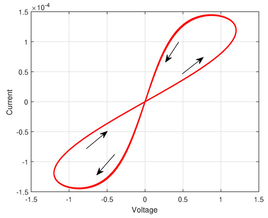
Figure 1.
The nonlinear behavioral model of the memristor.
For the propose of simplifying the mathematical model of the memristor on the premise of obtaining the pinched hysteresis feature, we select a surrogate memristor model.
where is the neuron self-inhibition, which represents as . and represent the memristive connection weights, which denotes as and ; and is the activation function. We assume that the solution of system (2) with initial conditions exists.
Regarding the characters of a memristor and simplified mathematical model of the memristor Figure 2, the parameters of systems are supposed to meet the following conditions
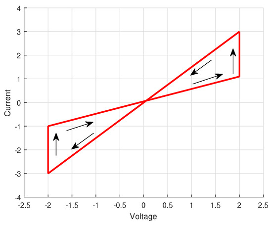
Figure 2.
The simplified mathematical model of the memristor.
Consider of N time-varying uncertain coupled MNNs as follows
then, the delayed coupled MNNs as drive system contains N identical MNNs is described as Equation (3), in which are the state variables of the dynamical networks. and are time-varying delays, which satisfy , , . We make the uncertainties as and . Then, is non-delayed coupled matrix, and is delayed coupled matrix. Additionally, we make and , and the following conditions are satisfied [32]
The constant stands for the coupling strength, the matrix is non-delayed inner connecting matrix, and the coupled matrix represents the topology structure of the whole networks.
Then, the following state-space equations represent the corresponding response system:
where stands for the state vector with initial condition . and are the response uncertainties and describes the nonlinear controller that will be constructed later. We choose the parameters similar to the drive system, that is,
Therefore, the drive-system (3) is modified as
Then, we obtain
where , , , .
We define the inner couple matrix as identity matrix. The measurable functions are
Consequently, from the set-valued mappings technique and differential inclusion theory, the Equation (6) can be transferred as:
Remark 1.
The interval parameters are introduced to transform Equations (3)–(11). Accordingly, considering the state dependence characters of the memristor, we derived measurable function Equations (8)–(10) to confirm the variables , and cannnot get the maximum and minimum values simultaneously. In other words, when or , the corresponding or , or may not be satisfied.
Similarly, we have the response system as
and , , .
2.2. Some Useful Definitions and Assumptions
Assumption 1.
The parameters , , , , are norm-bounded and time-varying, which satisfy
we set equals to , and equals to . . For measurable functions and (), we have , .
Assumption 2.
The activation function is bounded and Lipschitez-continuous. There is a real constant such that
for all , , , .
Assumption 3.
For all initial values , the solution of (11) is bounded, that is for .
Assumption 4.
Supposing universities are bounded, which means , (), and satisfy
and , , , and .
Lemma 1.
If P and Q represent the matrices with suitable dimensions, such that, such as
which .
Definition 1.
3. Fudamental Results
The current section presents the solution to the adaptive synchronization problem of uncertain coupled MNNs under the nonlinear control and its application.
Before starting our fundamental outcomes, the controller is designed as follows
where stands for the feedback controller matrix that will be constructed. , and , describe positive constants, and
Theorem 1.
Proof.
Based on the trajectory of , we get the derivative of as follows
According to Assumptions 1–3 and Lemma 1, we deduce
Similarly, we get
By usint Young’s inequality and Lemma 1, we have
For , we have
Then we get
and
Consider (18) and mentioned above, we conclude
Then, we take into account for deduce
then we make
Similarly, the derivative of is described as
Combing the mentioned above, we have
Accordin to Definition 1, we get , that is, we make can realize the projective synchronization among systems (12) and (13).
The proof is now completed. □
Corollary 1.
Suppose Assumptions 1–4 hold, the systems systems (11) and (12) can achieve projective synchronization with contrl inputs, if the parameters are choosen as , , which satisfy
Proof.
Consider the nonnegative function, for system (37), the Lyapunov function is proposed as follows
This proof can be obtained immediately by considering the uncertainties as zero in Theorem 1. Hence, it is neglected here. □
Remark 3.
During the process of synchronization, the control with discontinuous characteristics is essential to the converge of the error system. However, the stochastic disturbance from various uncertainties inevitably disturbs the practical communication among subsystems of coupled neural networks. Therefore, a simple adaptive method is proposed for the projective synchronization of the system (11) based on the designed Lyapunov function.
Theorem 2.
Proof.
The subsequent Lyapunov function is established for the error system
For the first of (42), we have
Similar to the proof of Theorem 1, combining with Definition 1, we can obtain
and
Accordingly, we conclude the gain matrix with adaptive controller (41) as follows
That is, with the synchronization criteria (21) and (46), systems (11) and (12) can realize the complete projective synchronization under the adaptive control approach (41).
The proof is now completed. □
Theorem 3.
Consider the encrypted chaotic sequences from drive system (11) are added to the plaintexts , then we get the transmitted signals as follows
Accordingly, the recovered signal is obtained based on decrypted chaotic from response system (12) as the following
Then, an adaptive observer synchronization of coupled MNNs approach is designed as:
and
where .
The proposed adaptive controller as follows
where are positive constants.
4. Numerical Simulations
The current section presents various numerical examples to evaluate the correctness of the developed theoretical results.
Example 1.
Projective synchronization.
Assume the three-dimensional coupled MNNs (11) and (12) consists three neural networks and the edge weights are 1. The topology structure of the system is illustrated as the coupling strength , the inner connecting matrix , coupled matrix , and are as follows
For systems (11) and (12), the time-varying delay are , and . The initial values for drive system are , then we make the intial valued for response system are . The active function is .
Based on the mismatched parameters for coupled MNNs transmission method, we make the following parameters
Taken into the following uncertainties into consideration, we have
According to Assumptions 1 and 2, we make
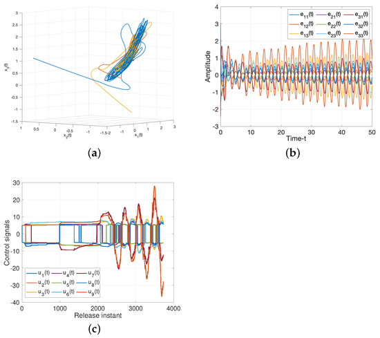
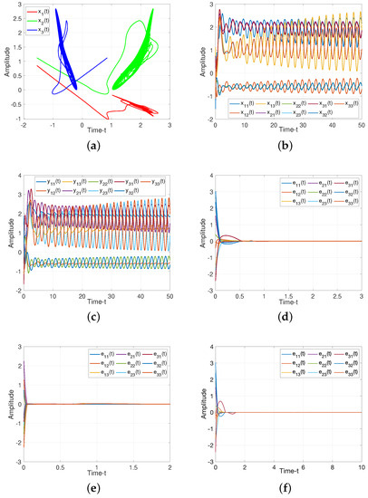
For drive/response systems (11) and (12), we choose three different initial values to illustrate the chaotic for such system, the dynamic trajectories of states without controller are presented in Figure 3. Additionally, Figure 3c shows the input of the ineffective control, which means the states of such system is chaotic under the ineffective control method, and the system will be controlled under the suitabl control methods as following.
For Theorem 1, when projective factor , we have the complete stable of error system. Then we set as control gains for feedback controller (19), as illustrated in Figure 4, such controller can guarantee the stability of the system. When projective factor , we obtain the antisynchronization between systems (11) and (12), which shown in Figure 4e.
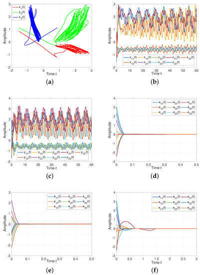
Figure 4.
Dynamic trajectories of systems (11) and (12). (a) Chaotic sequences of drive system (11); (b) States of drive system (11) without controller; (c) States of response system (12) without controller; (d) Synchronization error of system (18) under feedback controller (19) with ; (e) Anti-synchronization error of system(18) under feedback controller (19) with ; (f) Adaptive-synchronization error of system (18) under adaptive controller (41).
For Theorem 2, we verify the effect of adaptive controller for such systems. It can be seen from Figure 4f, the rationality and effectiveness of the designed controller (41)
Remark 4.
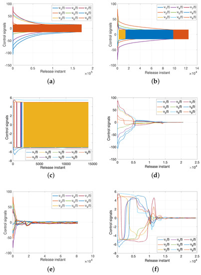
For controller, we define as follows
but the characteristic of will lead to a buffeting phenomenon; thus we replace to to alleviate this phenomenon. The Figure 5 illustrates the effective of such method. Figure 6a–c demonstrate the different types of controllers under buffeting phenomenon due to the factor, and Figure 6d–f show the corresponding controllers, which get away from the buffeting under the influence of .

Figure 5.
Dynamic trajectories of systems (11) and (12) without uncertainties. (a) Chaotic sequences of drive system (11); (b) States of drive system (11) without controller; (c) States of response system (12) without controller; (d) Synchronization error of system (18) under feedback controller (19) with ; (e) Anti-synchronization error of system (18) under feedback controller (19) with ; (f) Adaptive-synchronization error of system (18) under adaptive controller (41).

Figure 6.
Inputs from different types controllers. (a) Feedback controller (19) with buffeting phenomenon; (b) Feedback anti-controller with buffeting phenomenon; (c) Adaptive controller (41) with buffeting phenomenon; (d) Feedback controller (19) without buffeting phenomenon; (e) Feedback anti-controller without buffeting phenomenon; (f) Adaptive controller (41) without buffeting phenomenon.
For Corollary 1, we make the uncertainties as zeros, the states of (37) without control are presented in Figure 5a–c. It is shown that the error system (18) converges to zero gradually, which verify the Corollary 1 is reasonable.
Example 2.
Secure communication.
The secure communication process of the proposed algorithm is illustrated in Figure 7. We make the same parameters as Corollary 1. Two plaintexts are and . For the process of encryption, two encryption chaotic sequences and are chosen from the drive system (11). We combine plaintext signals and chaotic sequences, and the transmitted signals as shown in Figure 8. Consider the process of the decryption, two decryption chaotic sequences and are chosen from the corresponding response system (12). For the adaptive controller (51), we set , . Figure 9 illustrated the trajectories of plaintexts and decrypted signals. From Figure 10, we notice the error between plaintexts and decrypted signals converge to zero, which means the projective synchronization approach can solve the encryption/decryption problem effective in secure communication.
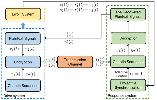
Figure 7.
Secure communication process of proposed algorithm.
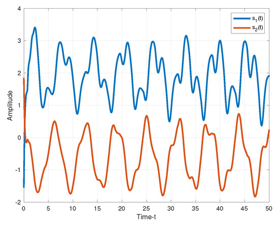
Figure 8.
The transmitted signals.
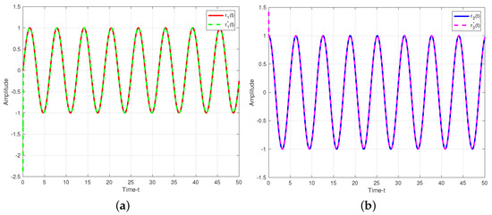
Figure 9.
Trajectories of plaintexts and decrypted siganls under adaptive control approach. (a) ; (b) .
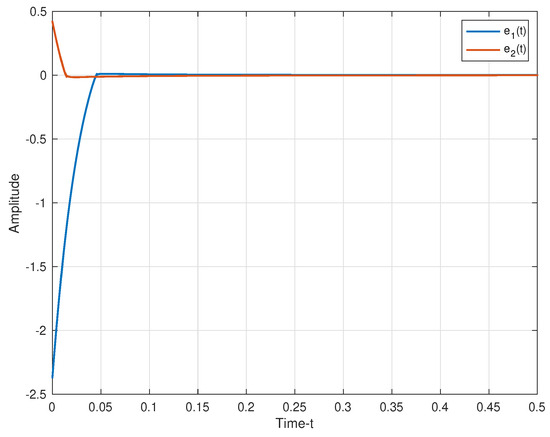
Figure 10.
The error between plaintexts and decrypted siganls.
Remark 5.
Comparing with current literature [40,41] for secure communication, the parameters in the proposed model, that is, and can not only demonstrate the special structure of MNNs, but also can build the internal connection between the sufficient condition and the projective synchronization approach under the multi-links coupled condition. Consequently, in terms of the effect of secure communication (e.g., number of keys, types of encryption and decryption), the proposed method is more flexible and expandable than other approaches.
5. Conclusions
This paper focused on the projective synchronization of coupled multi-links MNNs with uncertainties and delays that is time-varying. Aiming at the issue of parameter mismatch, the principle of extended comparison and a new approach were employed to transform the proposed system into one with interval parameters. Furthermore, according to the designed LKF, several sufficient criteria for projective synchronization were derived under the nonlinear controller. Finally, the chaotic sequences of drive and response systems were applied in signal encryption and decryption of secure communication. Based on the concept of projective synchronization, the adaptive control mechanism has been proposed to improve the effectiveness of signal decryption and decryption in secure communication.
Author Contributions
Methodology, Z.H. and M.Y.; Software, N.C. and X.W.; Formal analysis, N.C.; Investigation, Z.H. and X.W.; Resources, M.Y.; Writing—original draft, H.L.; Writing—review & editing, H.L. All authors have read and agreed to the published version of the manuscript.
Funding
This research received no external funding.
Institutional Review Board Statement
Not applicable.
Informed Consent Statement
Not applicable.
Data Availability Statement
Not applicable.
Acknowledgments
This work was supported by the National Natural Science Foundation of China (Grant No. 62106020; 62073263); the Fundamental Research Funds for the Central Universities (Grant No. FRF-IDRY-20-022); the China Postdoctoral Science Foundation (Grant No. 2021M690355); Postdoctoral Research Foundation of Shunde Graduate School of University of Science and Technology Beijing (Grant No. 2021BH008).
Conflicts of Interest
The authors declare no conflict of interest.
References
- Aliabadi, F.; Majidi, M.H.; Khorashadizadeh, S. Chaos synchronization using adaptive quantum neural networks and its application in secure communication and cryptography. Neural Comput. Appl. 2022, 34, 6521–6533. [Google Scholar] [CrossRef]
- Sham, E.E.; Vidyarthi, D.P. CoFA for QoS based secure communication using adaptive chaos dynamical system in fog-integrated cloud. Digit. Signal Process. 2022, 126, 103523. [Google Scholar] [CrossRef]
- Nguyen, Q.D.; Huang, S.C. Synthetic adaptive fuzzy disturbance observer and sliding-mode control for chaos-based secure communication systems. IEEE Access 2021, 9, 23907–23928. [Google Scholar]
- Chua, L. Memristor-the missing circuit element. IEEE Trans. Circuit Theory 1971, 18, 507–519. [Google Scholar] [CrossRef]
- Zhu, S.; Bao, H. Event-triggered synchronization of coupled memristive neural networks. Appl. Math Comput. 2022, 415, 126715. [Google Scholar] [CrossRef]
- Milano, G.; Miranda, E.; Ricciardi, C. Connectome of memristive nanowire networks through graph theory. Neural Netw. 2022, 150, 137–148. [Google Scholar] [CrossRef]
- Alsaedi, A.; Cao, J.; Ahmad, B.; Tian, X. Synchronization of master-slave memristive neural networks via fuzzy output-based adaptive strategy. Chaos Solitons Fractals 2022, 158, 112095. [Google Scholar] [CrossRef]
- Yu, T.; Wang, H.; Cao, J.; Xue, C. Finite-time stabilization of memristive neural networks via two-phase method. Neurocomputing 2022, 491, 24–33. [Google Scholar] [CrossRef]
- Lin, A.; Cheng, J.; Rutkowski, L.; Wen, S.; Luo, M.; Cao, J. Asynchronous fault detection for memristive neural networks with dwell-time-based communication protocol. IEEE Trans. Neural Netw. Learn Syst. 2022, 1–12. [Google Scholar] [CrossRef]
- Yuan, M.; Wang, W.; Wang, Z.; Luo, X.; Kurths, J. Exponential synchronization of delayed memristor-based uncertain complex-valued neural networks for image protection. IEEE Trans. Neural. Netw. Learn Syst. 2021, 32, 151165. [Google Scholar] [CrossRef]
- Zhu, P.; Cheng, L.; Gao, C.; Wang, Z.; Li, X. Locating multi sources in social networks with a low infection rate. IEEE Trans. Netw. Sci. Eng. 2022, 9, 1853–1865. [Google Scholar] [CrossRef]
- Zhou, C.; Wang, C.; Sun, Y.; Yao, W.; Lin, H. Cluster output synchronization for memristive neural networks. Inf. Sci. 2022, 589, 459–477. [Google Scholar] [CrossRef]
- Kashkynbayev, A.; Issakhanov, A.; Otkel, M.; Kurths, J. Finite-time and fixed time synchronization analysis of shunting inhibitory memristive neural networks with time-varying delays. Chaos Solitons Fractals 2022, 156, 111866. [Google Scholar] [CrossRef]
- Cheng, L.; Tang, F.; Shi, X.; Qiu, J. Finite-time and fixed-time synchronization of delayed memristive neural networks via adaptive aperiodically intermittent adjustment Strategy. IEEE Trans. Neural Netw. Learn Syst. 2022, 1–15. [Google Scholar] [CrossRef]
- Zhou, C.; Wang, C.; Yao, W.; Lin, H. Observer-based synchronization of memristive neural networks under DoS attacks and actuator saturation and its application to image encryption. Appl. Math. Comput. 2022, 425, 127080. [Google Scholar] [CrossRef]
- Chee, C.Y.; Xu, D. Chaos-based Mary digital communication technique using controlled projective synchronization. IEEE Proc.-Circ. Dev. Syst. 2006, 153, 357–360. [Google Scholar] [CrossRef]
- Mainieri, R.; Rehacek, J. Projective synchronization in three-dimensional chaotic systems. Phys. Rev. Lett. 1999, 82, 3042. [Google Scholar] [CrossRef]
- Fu, Q.; Zhong, S.; Jiang, W.; Xie, W. Projective synchronization of fuzzy memristive neural networks with pinning impulsive control. J. Frankl. Inst. 2020, 357, 10387–10409. [Google Scholar] [CrossRef]
- Chen, C.; Li, L.; Peng, H.; Yang, Y.; Mi, L.; Qiu, B. Fixed-time projective synchronization of memristive neural networks with discrete delay. Phys. Stat. Mech. Its Appl. 2019, 534, 122248. [Google Scholar] [CrossRef]
- Ding, Z.; Chen, C.; Wen, S.; Li, S.; Wang, L. Lag projective synchronization of nonidentical fractional delayed memristive neural networks. Neurocomputing 2022, 469, 138–150. [Google Scholar] [CrossRef]
- Kumar, R.; Sarkar, S.; Das, S.; Cao, J. Projective synchronization of delayed neural networks with mismatched parameters and impulsive effects. IEEE Trans. Neural Netw. Learn Syst. 2019, 31, 1211–1221. [Google Scholar] [CrossRef]
- Guo, R.; Lv, W.; Zhang, Z. Quasi-projective synchronization of stochastic complex-valued neural networks with time-varying delay and mismatched parameters. Neurocomputing 2020, 415, 184–192. [Google Scholar] [CrossRef]
- Yang, N.; Yu, Y.; Zhong, S.; Wang, X.; Shi, K.; Cai, J. Impulsive effects on weak projective synchronization of parameter-mismatched stochastic memristive neural networks. J. Frankl. Inst. 2021, 358, 5909–5930. [Google Scholar] [CrossRef]
- Wu, F.; Huang, Y. Finite-time synchronization and H∞ synchronization of coupled complex-valued memristive neural networks with and without parameter uncertainty. Neurocomputing 2022, 469, 163–179. [Google Scholar] [CrossRef]
- Rajchakit, G.; Sriraman, R. Robust passivity and stability analysis of uncertain complex-valued impulsive neural networks with time-varying delays. Neural Process Lett. 2021, 53, 581–606. [Google Scholar] [CrossRef]
- Li, H.L.; Hu, C.; Zhang, L.; Jiang, H.; Cao, J. Non-separation method-based robust finite-time synchronization of uncertain fractional-order quaternion-valued neural networks. Appl. Math. Comput. 2021, 409, 126377. [Google Scholar] [CrossRef]
- Peng, H.; Wei, N.; Li, L.; Xie, W.; Yang, Y. Models and synchronization of time-delayed complex dynamical networks with multi-links based on adaptive control. Phys. Lett. A 2010, 374, 2335–2339. [Google Scholar] [CrossRef]
- Sheikh, M.S. A complex network analysis approach for estimation and detection of traffic incidents based on independent component analysis. Phys. Lett. A 2022, 586, 126504. [Google Scholar] [CrossRef]
- Cheng, L.; Li, X.; Han, Z.; Luo, T.; Ma, L.; Zhu, P. Path-based multi-sources localization in multiplex networks. Chaos Solitons Fractals 2022, 159, 112139. [Google Scholar] [CrossRef]
- Suárez, L.E.; Markello, R.D.; Betzel, R.F.; Misic, B. Linking structure and function in macroscale brain networks. Trends Cogn. Sci. 2020, 24, 302–315. [Google Scholar] [CrossRef]
- Qin, X.; Wang, C.; Li, L.; Peng, H.; Ye, L. Finite-time lag synchronization of memristive neural networks with multi-links via adaptive control. IEEE Access 2020, 8, 55398–55410. [Google Scholar] [CrossRef]
- Zhao, H.; Zheng, M. Finite-time synchronization of coupled memrisive neural network via robust control. IEEE Access 2019, 7, 31820–31831. [Google Scholar] [CrossRef]
- He, W.; Luo, T.; Tang, Y.; Du, W.; Tian, Y.C.; Qian, F. Secure communication based on quantized synchronization of chaotic neural networks under an event-triggered strategy. IEEE Trans. Neural Netw. Learn. Syst. 2019, 31, 3334–3345. [Google Scholar] [CrossRef]
- Mobini, M.; Kaddoum, G. Deep chaos synchronization. IEEE Open J. Commun. Soc. 2020, 1, 1571–1582. [Google Scholar] [CrossRef]
- Shanmugam, L.; Mani, P.; Rajan, R.; Joo, Y.H. Adaptive synchronization of reaction–diffusion neural networks and its application to secure communication. IEEE Trans. Cybern. 2018, 50, 911–922. [Google Scholar] [CrossRef] [PubMed]
- Ouyang, D.; Shao, J.; Jiang, H.; Nguang, S.K.; Shen, H.T. Impulsive synchronization of coupled delayed neural networks with actuator saturation and its application to image encryption. Neural Netw. 2020, 128, 158–171. [Google Scholar] [CrossRef]
- Gupta, M.; Gupta, M.; Deshmukh, M. Single secret image sharing scheme using neural cryptography. Multimed. Tools Appl. 2020, 79, 12183–12204. [Google Scholar] [CrossRef]
- Xiu, C.; Zhou, R.; Liu, Y. New chaotic memristive cellular neural network and its application in secure communication system. Chaos Sol. Fractals 2020, 141, 110316. [Google Scholar] [CrossRef]
- Chen, L.; Yin, H.; Huang, T.; Yuan, L.; Zheng, S.; Yin, L. Chaos in fractional-order discrete neural networks with application to image encryption. Neural Netw. 2020, 125, 174–184. [Google Scholar] [CrossRef]
- Yuan, M.; Wang, W.; Luo, X.; Li, L. Asymptotic anti-synchronization of memristor-based BAM neural networks with probabilistic mixed time-varying delays and its application. Mod. Phys. Lett. B 2018, 32, 1850287. [Google Scholar] [CrossRef]
- Liu, A.; Zhao, H.; Wang, Q.; Niu, S.; Gao, X.; Chen, C.; Li, L. A new predefined-time stability theorem and its application in the synchronization of memristive complex-valued BAM neural networks. Neural Netw. 2022, 153, 152–163. [Google Scholar] [CrossRef] [PubMed]
Disclaimer/Publisher’s Note: The statements, opinions and data contained in all publications are solely those of the individual author(s) and contributor(s) and not of MDPI and/or the editor(s). MDPI and/or the editor(s) disclaim responsibility for any injury to people or property resulting from any ideas, methods, instructions or products referred to in the content. |
© 2023 by the authors. Licensee MDPI, Basel, Switzerland. This article is an open access article distributed under the terms and conditions of the Creative Commons Attribution (CC BY) license (https://creativecommons.org/licenses/by/4.0/).