Abstract
Electrochemical nitrate reduction (NO3−RR) has been recognized as a promising strategy for sustainable ammonia (NH3) production due to its environmental friendliness and economical nature. However, the NO3−RR reaction involves an eight-electron coupled proton transfer process with many by-products and low Faraday efficiency. In this work, a molybdenum oxide (MoOx)-decorated titanium dioxide nanotube on Ti foil (Mo/TiO2) was prepared by means of an electrodeposition and calcination process. The structure of MoOx can be controlled by regulating the concentration of molybdate during the electrodeposition process, which can further influence the electron transfer from Ti to Mo atoms, and enhance the binding energy of intermediate species in NO3−RR. The optimized Mo/TiO2-M with more Mo(IV) sites exhibited a better activity for NO3−RR. The Mo/TiO2-M electrode delivered a NH3 yield of 5.18 mg h−1 cm−2 at −1.7 V vs. Ag/AgCl, and exhibited a Faraday efficiency of 88.05% at −1.4 V vs. Ag/AgCl. In addition, the cycling test demonstrated that the Mo/TiO2-M electrode possessed a good stability. This work not only provides an attractive electrode material, but also offers new insights into the rational design of catalysts for NO3−RR.
1. Introduction
Ammonia (NH3) is essential in various industrial sectors, such as chemical production, refrigeration, and pharmaceuticals [1,2]. It also serves as a carbon-free fuel with a high hydrogen density (the NH3 molecule has a H content of 17.75% by weight), making it easily storable and transportable through existing infrastructures [3]. The Haber–Bosch process for NH3 production stands as the most significant inventions in chemical engineering. It relies on high-temperature (400–600 °C) and high-pressure (200–350 atm) reactions between N2 and H2 with a suitable catalyst [4,5,6]. Apart from the energy required for heating and pumping, the high-purity H2 utilized in this process is predominantly produced from natural gas, resulting in substantial greenhouse gas emissions [7,8]. Hence, there is considerable importance in developing a sustainable and environmentally friendly strategy for NH3 production. Electrocatalytic approaches are recognized for their energy-saving and environmentally benign nature, distinguished by simple equipment, mild state, high efficiency, and immense potential for application on a large scale [9,10].
Among these approaches, NH3 production from N2 and H2O has garnered significant attention [11,12]. However, the N≡N bond energy is notably high at 941 kJ mol−1, and N2 only dissolves sparingly in water [13]. Consequently, the energy utilization of nitrogen reduction reactions in the aqueous environment is limited, with NH3 production yields up to three orders of magnitude lower than those of the Haber–Bosch process [14]. Considering this, researchers have explored other nitrogen-containing compounds as NH3 synthesis sources and identified NO3− as a promising candidate. NO3− exhibits good solubility in water, and the N=O bond energy is relatively low at 204 kJ mol−1 [15,16]. In addition, NO3− is also a significant pollutant due to human activities, including excessive nitrogen fertilizer usage, fossil fuel combustion, and wastewater discharge, contributing to increased nitrate levels in water [17]. The World Health Organization (WHO) recommends that the level of nitrates in drinking water not exceed 50 mg L−1 [18]. Once nitrates are ingested by the human body, they undergo metabolism in the digestive system where they are converted into nitrites, thereby presenting a potential carcinogenic hazard [19]. Therefore, utilizing NO3− as a nitrogen source for NH3 synthesis not only enhances energy utilization efficiency and reduces greenhouse gas emissions, but also addresses the issue of NO3− pollution in the environment.
Recently, the electrocatalytic nitrate synthesis of ammonia (NO3−RR) has been investigated using metals such as Cu, Fe, Pt, Ag, and Mo [20,21,22,23,24]. Among them, Mo has attracted much attention due to its low price and good catalytic performance. Moreover, the nitrate reduction reaction process in nature is facilitated by an enzymatic cascade, where the Mo(IV) cofactor of nitrate reductase catalyzes the conversion of NO3− to NO2− [25]. This step plays a crucial role in determining the overall reaction rate [26]. Wang et al. reported MoO2 nanoparticles supported by molybdenum plate as an electrode for NO3−RR. Such MoO2 nanoparticles delivered a good activity for the conversion of NO3− to NH3 [27]. Zhong et al. reported a MoO/C catalyst capable of a stable reaction for 50 h, suggesting its potential in the treatment of nitrate-containing wastewater [28]. Song et al. found that MoOx exhibits a high affinity for adsorbing NO3− ions [29]. The Mo(IV) site can hinder the adsorption of NO2− and contributes to the conversion of *NO to *NOH [29]. Thus, MoOx with a Mo(IV) site can accelerate the conversion of electrochemical NO3− to NH3 and limit NO2− generation, resulting in the efficient production of NH3.
Generally, the nanostructure is favorable to enlarge the interface between electrode and electrolyte, and the construction of a nanocomposite can endow the catalyst with more active sites [30,31,32]. Xiong et al. prepared platinum nanoparticles embedded on nickel oxide nanosheets, which can serve as a electrocatalyst for boosting NO3− transfer [33]. Wang et al. constructed ultra-small iron oxide nanoparticles on carbon nanotubes, which can enlarge the active surface area and accelerate ion transfer [34]. All these studies have demonstrated that nanomaterials have the effect of promoting full solid-liquid phase contact. As a nontoxic and abundant material, TiO2 is one of the hot spots in photochemistry and electrochemistry. TiO2 nanotube arrays (TNTAs) can be easily prepared and serve as the substrate with a large surface area to support active materials [35,36,37]. Inspired by this, we anticipated that decorating MoOx onto the surface of TNTAs to form a nanocomposite structure can enlarge the active area and enhance the ion transfer from electrolyte to electrode.
In this work, MoOx-loaded TNTAs was prepared on Ti foil (Mo/TiO2) by means of an electrodeposition and calcination process. This can directly serve as the electrode for NO3−RR. The TNTAs as the substrate can offer a large surface area to support MoOx. The Mo/TiO2 nanocomposite structure was confirmed by SEM and TEM measurement. Notably, XPS measurement further revealed the electron transfer behavior between Ti and Mo atoms. The electron transfer can be modulated by regulating the concentration of molybdate during the electrodeposition process. By optimizing the electrodeposition conditions, the obtained Mo/TiO2-M delivered a high NH3 yield of 5.18 mg h−1 cm−2 at −1.7 V vs. Ag/AgCl and a Faraday efficiency of 88.05% at −1.4 V vs. Ag/AgCl in 0.1 M NaNO3 solution. It also maintained a Faraday efficiency of over 80% under five consecutive cycle tests. This work not only presents a highly promising electrode material, but also offers new insights into the rational design of Mo-based nanocomposites for NO3−RR.
2. Results and Discussion
2.1. Morphological and Structural Analysis of Catalysts
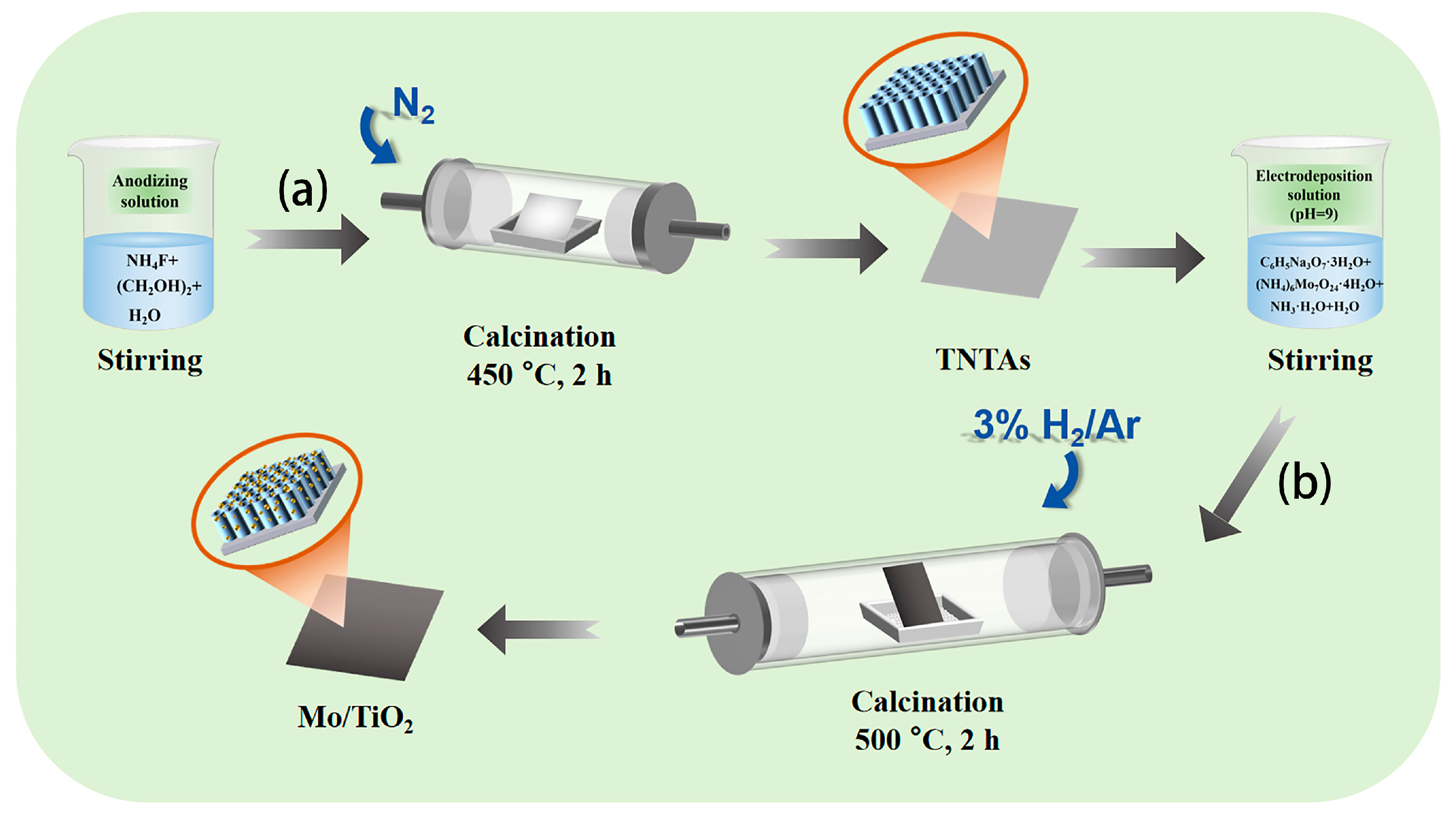
Figure 1 shows the two-step process to fabricate the Mo/TiO2 electrode. Firstly, TiO2 nanotube arrays were formed on Ti foil (TNTAs) by using anodization process (Figure 1a) [38], and then Mo was further loaded onto the TNTAs using the electrodeposition method and finally annealed under 3% H2/Ar atmosphere to prepare Mo/TiO2 (Figure 1b). The Mo/TiO2 can directly serve as the electrode for NO3−RR.

Figure 1.
Schematic illustration of the two-step synthesis process of the Mo/TiO2 electrodes: (a) anodization and then calcination under a N2 atmosphere at 450 °C for 2 h to prepare TNTAs; (b) electrodeposition and then calcination in 3% H2/Ar at 500 °C for 2 h.
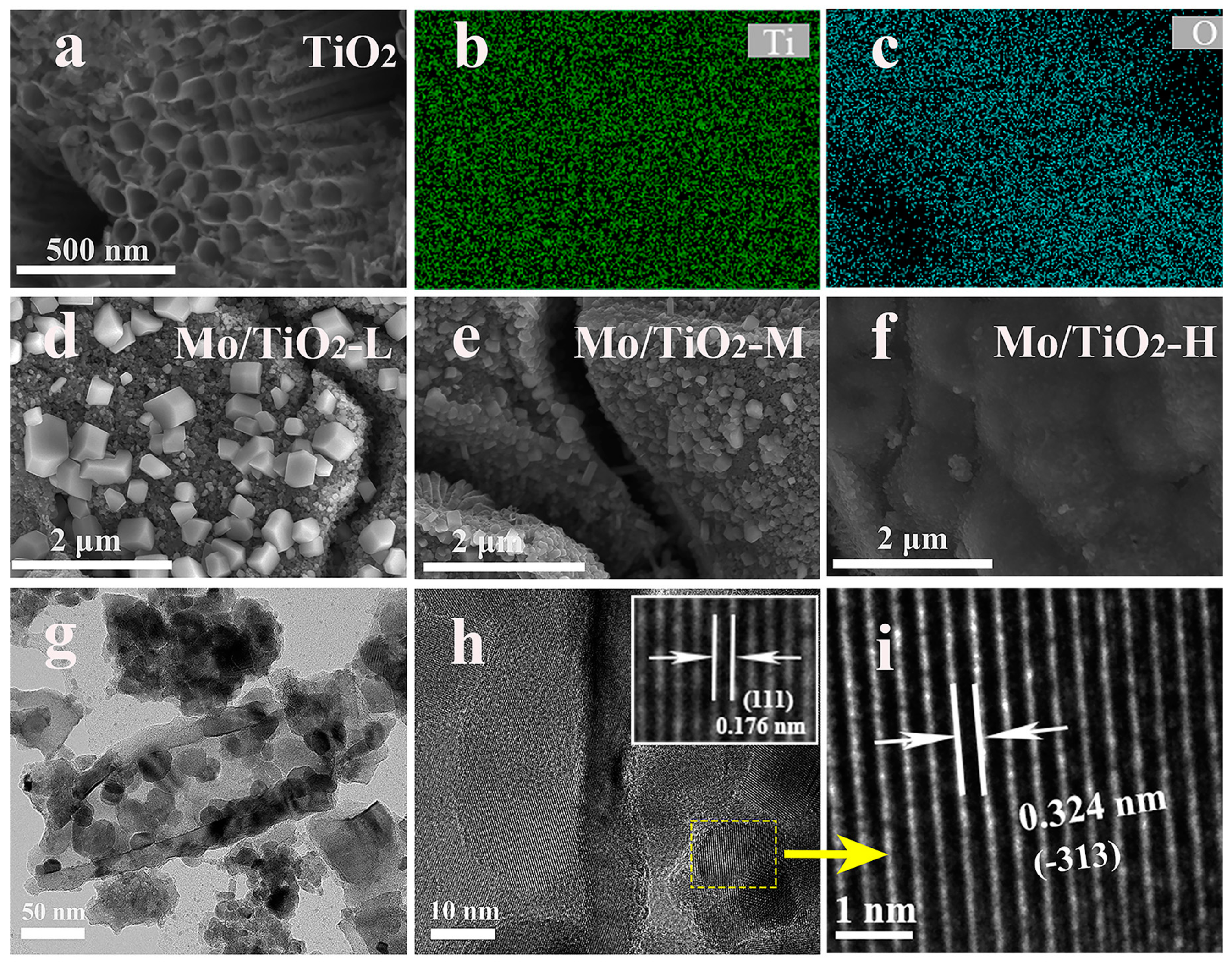
As shown in Figure 2a, the nanotube structure of the TNTAs was observed, and TNTAs with a tube diameter of 100 nm uniformly covered the Ti foil. The EDS mapping images (Figure 2b,c) show that Ti and O elements are distributed on TNTAs. TNTAs with a nanotube array structure can be a promising substrate to support active materials, and can offer a further pathway for ion transfer from electrolyte to electrode [35]. It was observed that the particle size of molybdenum oxide particles grown on the surface of the nanotubes gradually decreased with the increase in molybdate concentration in the electrodeposition solution. The SEM image of Mo/TiO2-L (Figure 2d) displays some nanoparticles on TNTAs. With increased molybdate concentration, relatively small particles can be found on the surface of TNTAs, as shown in Figure 2e,f, which is ascribed to the kinetics of electrochemical deposition. In general, the concentration of the electrolyte is proportional to the uniformity of the electrodeposition. A high concentration of molybdate allows a sufficient amount of Mo species to be adsorbed onto the electrode surface, thus resulting in the uniform growth of the Mo layer. In the electrolyte with low molybdate concentration, the nucleation of Mo is controlled by the diffusion of Mo species. This is because there are insufficient Mo species near the electrode region, causing the Mo species to preferentially adsorb on the nucleated particles with a larger radius of curvature. Therefore, the particles with a larger size can be formed for Mo/TiO2-L (Figure 2d). To further confirm the nanocomposite structure, TEM measurement was carried out. The Mo/TiO2 active material was scraped off and dispersed in ethanol for TEM measurement. As shown in Figure 2g, the nanotube structure can be clearly observed with a wall thickness of 15 nm. Notably, some nanoparticles can be found inside and outside the nanotube with a size of 25–30 nm. The high-magnification TEM image (Figure 2h inset) shows a clear boundary between nanoparticles and nanotubes. A highly ordered fringe with an interplanar distance of 0.176 nm can be observed in the nanotube region (Figure 2h inset), which corresponds to the (111) plane of the TiO2 phase [39]. Moreover, the high-magnification TEM image of the nanoparticles (Figure 2i) displays a lattice fringe with a d-space of 0.324 nm, suggesting the (−313) plane of MoO2. The above results indicate the successful formation of a Mo/TiO2 nanocomposite structure by means of the electrochemical deposition process [40].
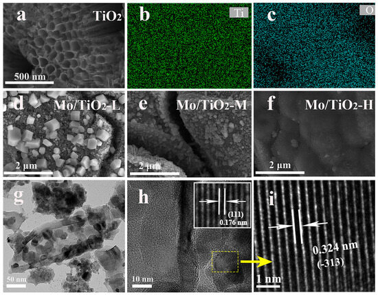
Figure 2.
(a) SEM image of TNTAs, and (b,c) the corresponding EDS mapping images. SEM images of (d) Mo/TiO2-L, (e) Mo/TiO2-M, and (f) Mo/TiO2-H. (g,h) TEM and (i) HR-TEM images of Mo/TiO2-M.
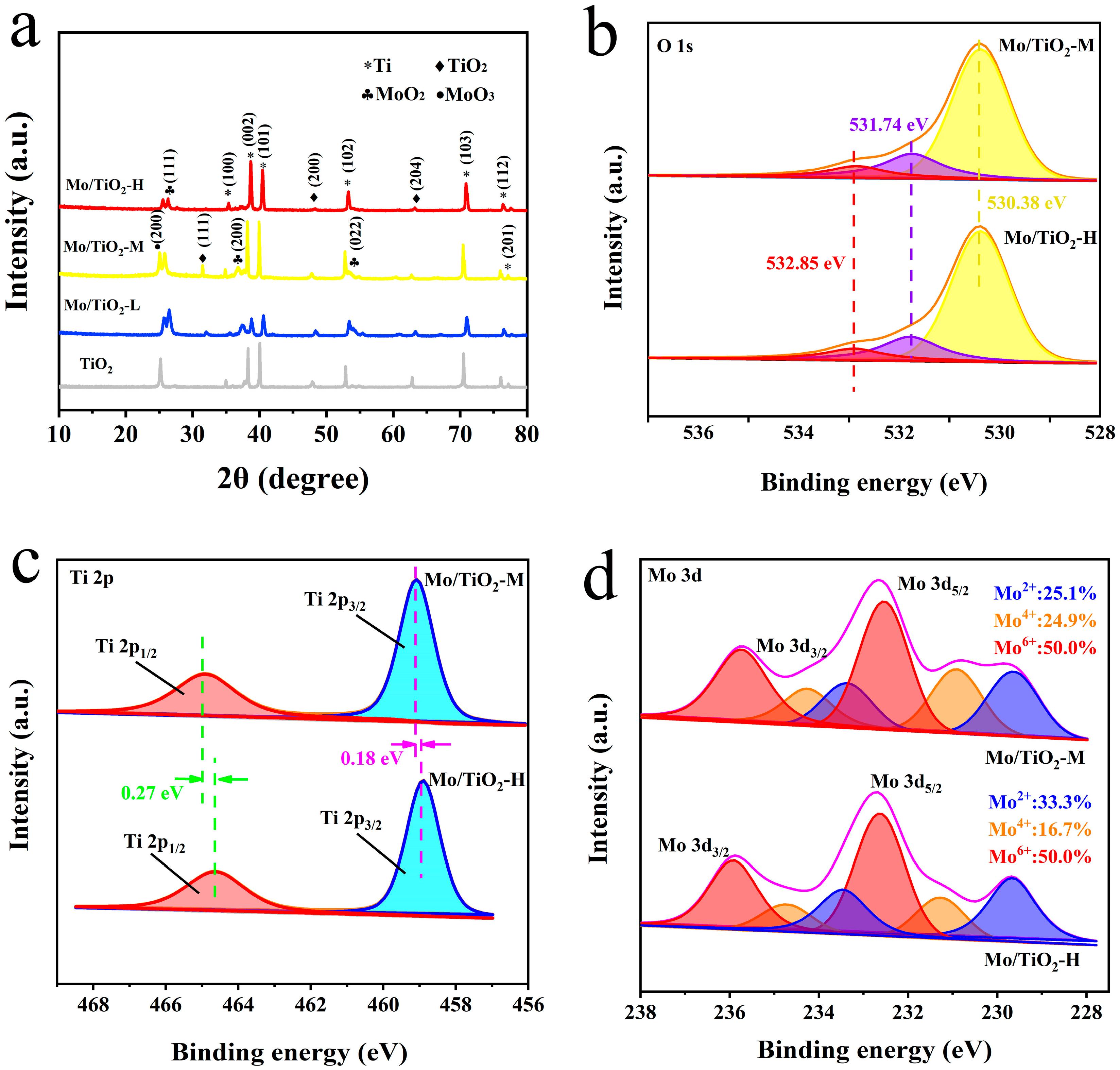
The successful preparation of TNTAs and Mo/TiO2 electrodes could be further confirmed through XRD characterization. As shown in XRD patterns (Figure 3a), the peaks at 17.5°, 19.2°, 20.1°, 26.5°, 35.3°, 38.1°, and 38.7° (PDF#44-1294) are ascribed to the (100), (002), (101), (102), (103), (112), and (201) planes of Ti. The characteristic peaks at 15.7°, 20.0°, and 31.3° (PDF#97-001-5328) are observed in all samples, corresponding to the (111), (200), and (204) planes of TiO2. Moreover, the peaks at 12.9°, 18.50°, 26.7° (PDF#97-010-8875), and 12.5° (PDF#97-008-6426) correspond to the (111), (211), and (022) planes of MoO2 and the (200) plane of MoO3, respectively. The peaks of TiO2 can still be observed after Mo loading, indicating that the electrodeposition process cannot influence the crystal structure of TiO2. In addition, the intensity of new peaks corresponding to MoOx decreased with the increase in molybdate concentration. This could be due to the smaller grain size of MoOx, which is ascribed to the SEM results. In addition, the grain size of samples was calculated using the Scherrer equation, D = Kγ/(Bcosθ), where K is Scherrer’s constant (0.89), γ is the wavelength of the X-rays (1.54056 Å), B is the half-peak height width, and θ is the Bragg angle. Therefore, the grain size of Mo/TiO2-L, Mo/TiO2-M, and Mo/TiO2-H was calculated to be 30.8, 26.8, and 22.6 nm, respectively.
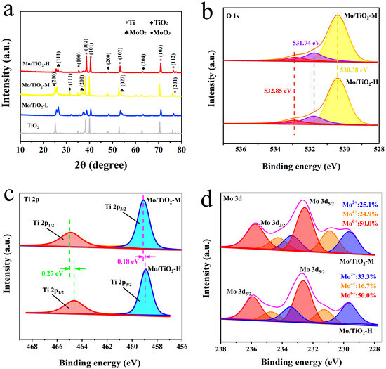
Figure 3.
(a) XRD patterns of TiO2, Mo/TiO2-L, Mo/TiO2-M, and Mo/TiO2-H. High-resolution XPS spectra of Mo/TiO2-M and Mo/TiO2-H: (b) O 1s, (c) Ti 2p, and (d) Mo 3d regions.
The surface chemistry of Mo/TiO2-M and Mo/TiO2-H was further investigated using XPS. The survey scan XPS spectrum shows the photoelectron lines with binding energies (BEs) at three peaks of 532, 460, and 233 eV corresponding to the O 1s, Ti 2p, and Mo 3d signals (Figure S1). As shown in Figure 3b, the peaks of O 1s with BEs at 530.38 and 532.85 eV are attributed to lattice oxygen and physically adsorbed oxygen, respectively [41,42]. In addition, the peak with BE at 531.74 eV corresponds to chemically adsorbed oxygen. This could be due to the fact that the oxygen defects on the surface after H2 treatment, and the positively charged defection sites can adsorb O2 to become reactive oxygen species [34,43]. As displayed in Figure 3c, the peaks with BEs at 460.18 and 464.90 eV correspond to the spin-orbit splitting peak of Ti 2p1/2 and Ti 2p3/2, respectively, proving the existence of Ti4+ [44]. Notably, compared with the Mo/TiO2-H sample, the Ti 2p1/2 and Ti 2p3/2 peaks display positive shifts of 0.18 and 0.27 eV for Mo/TiO2-M, indicating that the structure of MoOx could influence the local chemical states of Ti4+. According to a previous report, oxygen defect could be formed after H2 treatment, which can reduce Ti4+ into Ti3+ [45]. However, almost no Ti3+ was detected in the two samples, possibly due to the low amount of Ti3+. The positive shift could be explained by the grain size of MoOx, in which more interaction could occur between Mo and Ti atoms. Figure 3d demonstrates the Mo 3d XPS spectra of Mo/TiO2-M and Mo/TiO2-H. The Mo 3d in the samples are consist of three spin-orbit splitting components. The two peaks at BEs of 229.64 and 233.37 eV are attributed to the Mo 2d5/2 and Mo 2d3/2 of Mo2+ [46]. Additionally, the peaks at BEs of 230.91, 234.26, 232.54, and 235.74 eV are attributed to the Mo 2d5/2 and Mo 2d3/2 of Mo4+ and the Mo 2d5/2 and Mo 2d3/2 of Mo6+, respectively [46,47]. Notably, negative shifts in the peak position of Mo/TiO2-M can be found compared with Mo/TiO2-H. This indicates the electron transfer to Mo atoms. Therefore, the existence of electron transfer from Ti to Mo atoms is speculated. According to the d-band center theory proposed by Norskov et al. [48], the active site of Mo in Mo/TiO2-M could exhibit a rising d-band center compared with Mo/TiO2-H. This suggested that less electrons would fill the antibonding orbitals, thus increasing the adsorption energy between intermediate species and active site [49]. Hence, the binding energy of intermediate species in NO3−RR could be adjusted by rationally regulating the grain size of MoOx. Furthermore, the relative amounts of Mo in each valence state were calculated through the peak areas. As displayed in Figure 3d, it was found that Mo(IV) is more abundant in Mo/TiO2-M. This implies that the structure of MoOx (Figure 2d–f and 3a) and the valence of Mo (Figure 3d) can be influenced by rationally designing the concentration of molybdate during electrodeposition.
2.2. Electrocatalytic Performance of Electrodes for Mo/TiO2
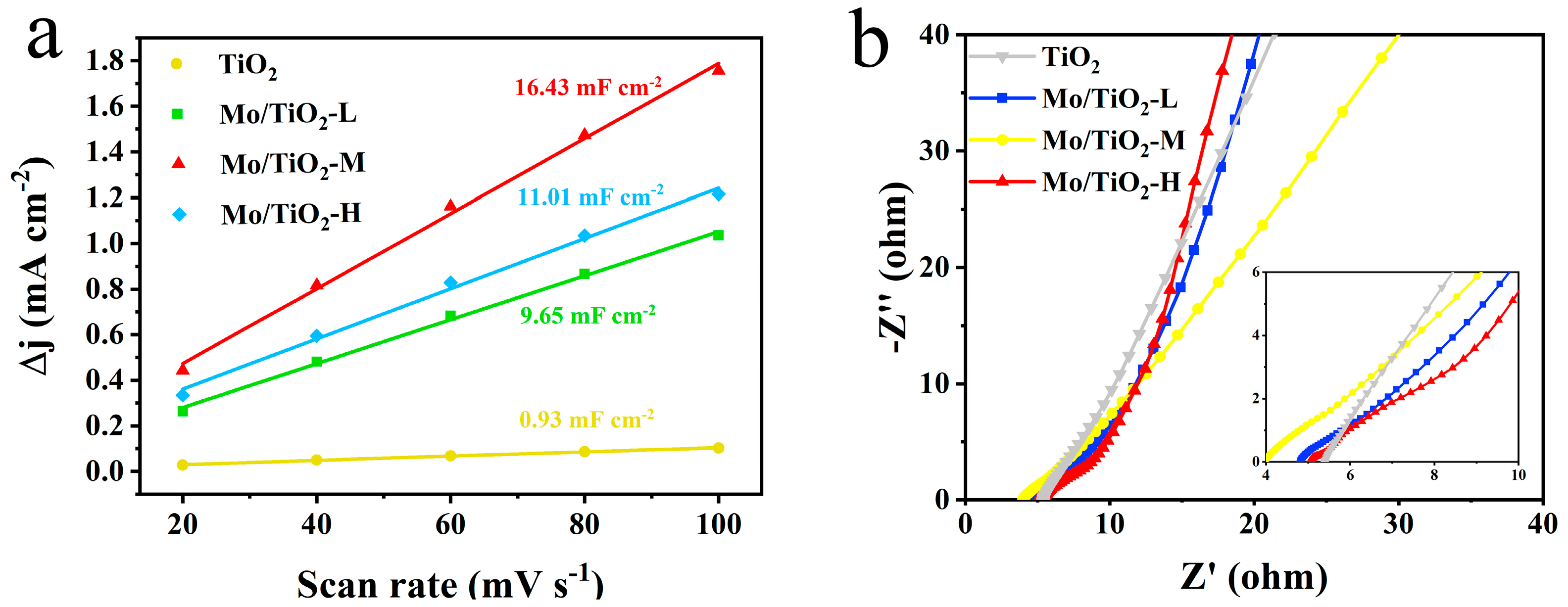
CV, LSV, and EIS measurements were conducted in an H-type three-electrode system in 0.05 M Na2SO4 electrolyte to compare the electrochemical performance of different samples. The CV tests were firstly conducted at different scan rates (Figure S2) to determine the electric double-layer capacitances (Cdl). Notably, the electrochemical active surface area (ECSA) was positively correlated with Cdl [50,51]. The Cdl for TiO2, Mo/TiO2-L, Mo/TiO2-M, and Mo/TiO2-H were 0.93, 9.65, 16.43, and 11.01 mF cm−2, respectively (Figure 4a), demonstrating that Mo/TiO2-M has a significantly greater ECSA than other concentrations. The greater ECSA for Mo/TiO2-M can be ascribed to its appropriate particle size. As shown in Figure 2d–f, the high concentration of molybdate results in the formation of a dense MoOx layer on the surface of TNTAs, thus leading to the reduction of the surface area for the nanoarray electrode. Conversely, Mo/TiO2-L, prepared with a low molybdate concentration, exhibits a larger size of particles, which decreases the solid-liquid contact surface. Therefore, the result indicates that Mo/TiO2-M could behave better for NO3−RR. This result can also be proven by the EIS measurement. Figure 4b shows the Nyquist plots of TiO2, Mo/TiO2-L, Mo/TiO2-M, and Mo/TiO2-H. In the high frequency region, the charge transfer resistance (Rct) and the electrolyte contact resistance (Re) are reflected by the intercepts of the radius of the high frequency arc on the real axis and the Nyquist plots, respectively [52]. The Rct of the Mo/TiO2-M electrode is much smaller than that of the other electrode, indicating faster charge transition [53]. Moreover, since TiO2 is a semiconductor, its conductivity is the worst, resulting in the smallest Rct. At low frequency, the perpendicularity of the lines of Mo/TiO2-L and Mo/TiO2-H are as similar as TiO2, indicating that their ion diffusion is close.
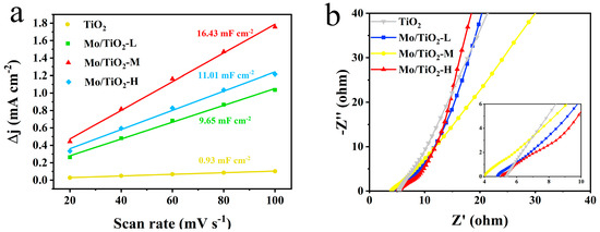
Figure 4.
(a) Double-layer capacitances of TiO2, Mo/TiO2-L, Mo/TiO2-M, and Mo/TiO2-H electrodes. (b) Nyquist plots of TiO2, Mo/TiO2-L, Mo/TiO2-M, and Mo/TiO2-H electrodes.
The LSV curves of the Mo/TiO2-M catalyst were tested in the electrolyte with and without nitrate-N at a scan rate of 5 mV s−1 to characterize whether it has NO3−RR catalytic properties. As shown in Figure 5a, it is evident that the current density of the LSV curve with NO3− in 0.05 M Na2SO4 is larger than that of the other one, ranging from −1.1 V vs. Ag/AgCl to −1.4 V vs. Ag/AgCl, which proves that Mo/TiO2-M has NO3−RR properties. Moreover, it is widely known that nitrate reduction is an eight-electron transfer process. In addition, the NH3 yield and Faraday efficiency of samples are essential factors in evaluating NO3−RR electrocatalytic properties. For this reason, UV spectroscopy was used to measure the concentration of NH3+ and NO2−. As shown in Figure S3, the linear fitting results correspond to the absorbance versus concentration curves of NH3+ and NO2−. The concentrations of the corresponding ions can be obtained from the measured absorbance and the standard curve.
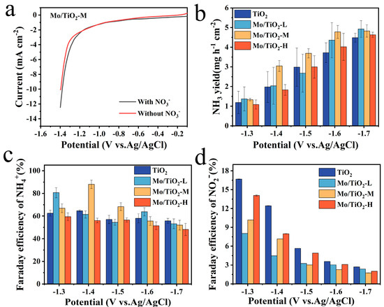
Figure 5.
(a) LSV curves of Mo/TiO2-M in 0.05 M Na2SO4 solution with and without NO3− at a scan rate of 5 mV s−1. The NH3 yield of (b) TiO2, Mo/TiO2-L, Mo/TiO2-M, and Mo/TiO2-H at the corresponding potentials. FE of NH4+ of (c) TiO2, Mo/TiO2-L, Mo/TiO2-M, and Mo/TiO2-H. FE of NO2− of (d) TiO2, Mo/TiO2-L, Mo/TiO2-M, and Mo/TiO2-H.
Figure 5b shows that the most preferred NH3 production of TiO2, Mo/TiO2-L, Mo/TiO2-M, and Mo/TiO2-H was reached at −1.6 V vs. Ag/AgCl, as the NH3 yield did not change much as the voltage continued to increase. Additionally, the highest NH3 productions of samples are reached at −1.7 V vs. Ag/AgCl. Among them, Mo/TiO2-M and Mo/TiO2-H exhibit the highest NH3 yields, around 5.18 mg h−1 cm−2 and 5.20 mg h−1 cm−2, respectively. Moreover, as shown in Figure 5c, the highest FE was 88.05%, corresponding to Mo/TiO2-M at −1.4 V vs. Ag/AgCl. Meanwhile, the highest FEs of 65.50%, 85.98%, and 63.91% were achieved for TiO2, Mo/TiO2-L, and Mo/TiO2-H, respectively. It can be seen that the FEs of Mo/TiO2-M remain at a high value at different voltages. This indicates that Mo/TiO2-M has superior NO3−RR performance, which may be due to the appropriate grain size of MoOx in Mo/TiO2-M. Moreover, Table S1 compares the NO3−RR performance of Mo/TiO2-M with other previously reported electrodes. The FE and NH3 yields of the Mo/TiO2-M electrode are comparable to most of the previous cathodes, further indicating the good activity of the as-prepared Mo/TiO2-M electrode [27,54,55,56,57,58,59].
Furthermore, the generation properties of the byproduct NO2− at each potential were also evaluated, as shown in Figure 5d. It was found that all MoOx-loaded samples inhibited NO2− generation compared to TiO2, with the strongest inhibition achieved by Mo/TiO2-M at voltages of −1.5–1.7 V vs. Ag/AgCl. Additionally, the change in the amount of NO3− in the electrolyte (Figure S5a) was measured, and then the amount of N2 produced during the NO3−RR reaction was calculated. As shown in Figure S5b, the quantity of N2 decreases with the increase in voltage, and no N2 is produced at −1.7 V vs. Ag/AgCl for any of the electrodes.
Based on the above test and analysis, Mo/TiO2-M was selected to operate a cycling test at −1.4 V vs. Ag/AgCl. As shown in Figure 6a, NH3 production exceeded 3 mg h−1 cm−2 and that Faraday efficiency stabilized over 80% in all groups. Cycling evaluation further highlighted Mo/TiO2-M’s outstanding and steady NO3−RR performance at −1.4 V vs. Ag/AgCl. Furthermore, a leaching test was conducted to determine possible Mo species in the electrolyte [60]. After the NO3−RR process, the concentration of Mo elements in the electrolyte was measured at only 0.0148 mg/L, suggesting almost no dissolution of Mo. Figure S6 displays the SEM image of the Mo/TiO2-M electrode after cycling tests. It is clear that no significant change can be observed, and nanoparticles are evident on the surface of the electrode. Figure 6b compares the XRD patterns of the Mo/TiO2-M electrode before and after cycling tests. Notably, almost no change can be seen, indicating the good structure stability of the Mo/TiO2-M electrode.
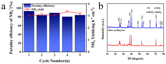
Figure 6.
(a) NH3 yields and FE of Mo/TiO2-M at −1.4 V (vs. RHE) for five cycling tests. (b) XRD patterns of Mo/TiO2-M before and after cycling tests.
3. Experimental Methods
3.1. Materials
Titanium foil (0.3 mm thickness, 99.9% of purity) was supplied from Tianjin Xingboguangwang Metal Co (Tianjin, China). Ammonium molybdate tetrahydrate ((NH4)6Mo7O24·4H2O), sodium nitroferricyanide dihydrate (C5FeN6Na2O·2H2O), and sodium sulfate (Na2SO4) were purchased from Shanghai Titan Scientific Co. (Shanghai, China). Chemical reagents such as sodium citrate trihydrate (C6H5Na3O7·3H2O), salicylic acid (C7H6O3), ammonia (NH3·H2O), ammonium fluoride (NH4F), potassium nitrate (KNO3), sodium hydroxide (NaOH), sulfamic acid (NH2SO3H), hydrochloric acid (HCl, 36–38%), sulfanilamide (C6H8N2O2S), sodium hypochlorite (NaClO), phosphoric acid (H3PO4), ethylene glycol (CH2OH)2, anhydrous ethanol (C2H5OH), and naphthylenediamine hydrochloride (C12H14N2·2HCl) were obtained from Kelong Chemical Co (Chengdu, China). All chemical reagents used for the synthesis of Mo/TiO2 were of analytical grade and were used as-is. Deionized water (18.25 MΩ·cm) used throughout the experiment was from an ultrapure water system.
3.2. Preparation of Electrode Material
3.2.1. Pre-Treatment of Ti
The pre-cut Ti foil with 2 cm × 1 cm × 0.03 cm dimensions was sanded with 800- and 1200-mesh metallographic sandpaper to produce a silvery luster on the surface. Subsequently, the processed Ti sheets were ultrasonically washed with ethanol for 20 min and deionized water for 20 min [61]. Then, the Ti foil was rinsed with deionized water to effectively remove the residual organic impurities on the surface during ultrasonic cleaning.
3.2.2. Preparation of TNTAs
Uniformly aligned TNTAs were grown on the surface of Ti foil using an anodic oxidation strategy. Dissolve ammonium fluoride (NH4F) (0.5 g) in deionized water (2 mL) and ethylene glycol (C2H6O2) (98 mL) to prepare electrolyte solution successively. Then, the Ti foil and platinum (Pt) electrode, which were cleaned as described above, were used as anode and cathode, respectively. The distance between the anode and the cathode was adjusted to be 3 cm approximately and reacted by a constant voltage device at 30 V for two hours. After that, the Ti foil was washed with anhydrous ethanol and placed in a tube furnace to be calcined for 2 h at 450 °C in an air environment. Finally, TNTAs with anatase phase were successfully produced.
3.2.3. Preparation of Mo/TiO2 Electrode
A certain mass of ammonium molybdate tetrahydrate solid ((NH4)6Mo7O24·4H2O) and 2.2075 g of sodium citrate (C6O7H5Na3·2H2O) were added into deionized water (50 mL) to prepare four groups of samples (0 M, 0.05 M, 0.1 M, and 0.2 M molybdate). NH3·H2O was added to the mixture after stirring to bring the pH up to 9. The prepared TNTA was used as the working electrode, a platinum (Pt) sheet as the auxiliary electrode, and Ag/AgCl as the reference electrode. Meanwhile, the current density was −20 mA cm−2, and the electrodeposition time was set to 20 min. After the process was completed, the samples were cleaned with deionized water and then put in a tube furnace to be calcined in 3% H2/Ar at the rate of 50 mL min−1 for 2 h. Finally, the electrodes were successfully produced, and the materials with different concentration of molybdate (0, 0.05 M, 0.1 M, and 0.2 M) were named as TiO2, Mo/TiO2-L, Mo/TiO2-M, and Mo/TiO2-H, respectively.
3.3. Characterization
The Ag/AgCl potential was converted to a reversible hydrogen electrode (RHE) using the Nernst equation: . All data were collected on a CHI660E electrochemical workstation (Shanghai CH Instruments, Shanghai, China). The crystal structure of the processed samples was characterized through X-ray diffraction (XRD) using a MiniFlex600 (Rigaku, Tokyo, Japan) with Cu-Kα radiation (λ = 0.154056 nm) at an ambient temperature (25 °C) and 2θ values ranging from 10 to 80 °. Energy dispersive spectroscopy (EDS) spectra and scanning electron microscopy (SEM) graphics were obtained using an FEI Quanta 250 (Regulus 8230U, Hitachi, Japan). A K-alpha spectrometer (Thermo Scientific, Waltham, MA, USA) equipped with a monochromatic Al Kα X-ray source (1486.6 eV photons) was used to perform X-ray photoelectron spectroscopy (XPS). Images from a transmission electron microscope (TEM) were captured at 200 kV using a Libra 200FE (Zeiss, Oberkochen, Germany). The concentration of ions in electrolyte was determined using an optima 7000DV inductively coupled plasma optical emission spectrometer (ICP-OES, Thermo Scientific, Waltham, MA, USA)
3.4. Electrochemical Measurement
The above-made electrode was used as the working electrode (1 cm × 1 cm), a Pt sheet as the counter electrode (1 cm × 1 cm), and Ag/AgCl as the reference electrode, placed in an H-type electrolyzer. The electrolyte was 0.1 M NO3−-N solution containing 0.05 M Na2SO4. The nitrate solution was then tested by i-t for one hour, testing the NH3 production at constant voltage to obtain the optimum operating voltage. The reacted cathode solution was collected for subsequent measurements.
Cyclic voltammetry (CV) was performed at −0.1 to 0 V against Ag/AgCl with a sampling rate of 20 to 100 mV s−1 with an interval of 20 mV s−1 in order to estimate the double layer capacitance (Cdl) of samples. Electrochemical impedance spectroscopy (EIS) was performed in an aqueous solution comprising 0.05 M Na2SO4. Additionally, the EIS measurements were performed in a frequency range from 0.01 to 100,000 Hz with an amplitude of sinusoidal AC voltage of 5 mV and 2 points per decade. Then, linear scanning voltammetry (LSV) was performed in the voltage range of −1.4–0 V (vs. RHE) for the tests.
3.5. Determination of Ion Concentration
UV spectroscopy was used to measure the concentrations of ammonium and nitrite ions. The method is as follows:
3.5.1. Nitrite-N Detection
Five groups of sodium nitrite solutions (0, 0.25, 0.5, 1, 2, and 3 μg/mL) were prepared separately, 1 mL of the Griess reagent was added, and then the solution was left to develop color for 10 min. The absorbance was measured at 540 nm using a UV spectrophotometer, and the standard concentration curve of nitrite was plotted. Diluting the cathode solution after the reaction to a measurable concentration range, 1 mL of the Griess reagent was added into it, and then the absorbance was measured. The corresponding nitrite concentration was calculated according to its standard concentration graph.
3.5.2. NH3-N Detection
Five groups of NH4+ solution (0, 1, 2, 3, and 4 μg/mL, respectively) were prepared. A total of 2 mL of colorant, 1 mL of oxidant, and 200 μL of catalyst were added sequentially, and then the solution was left to develop color by avoiding light for one hour. The absorbance was measured at 660 nm using a UV spectrophotometer, and the standard concentration curve of NH4+ was plotted. Diluting the NH4+ concentration after the reaction to a measurable concentration range, the three solutions were added in turn like the steps mentioned above, and then the absorbance was measured. The corresponding NH4+ concentration was calculated according to its standard concentration graph.
3.6. Product Calculation (Yield and Faraday Efficiency)
The NH3 yield was calculated using the following equation:
where C (NH3) is the measured concentration of NH3−N (aq), V (50 mL) is the volume of the cathode cell electrolyte, t (3600 s) is the electrochemical reaction time, and S (1 cm × 1 cm) is the surface area of the working electrode.
The Faraday efficiency (FE) was calculated using the following equation:
where F is Faraday’s constant (96485 C mol−1) and Q is the total charge across the electrolyte.
4. Conclusions
In summary, Mo/TiO2 nanocomposite material was fabricated through a two-step method. Such Mo/TiO2 can be used as a catalyst for NO3−RR and have good catalytic activity and performance. Both SEM and TEM results illustrated that MoOx nanoparticles were uniformly loaded onto TNTAs. It was observed that the particle size of molybdenum oxide particles grown on the surface of the nanotubes can be controlled by regulating the molybdate concentration in the electrodeposition process. In addition, the XPS results revealed the existence of electron transfer from Ti to Mo atoms in the Mo/TiO2 nanocomposite material, which could be controlled by regulating the grain size of MoOx. The electron transfer facilitated the upward shift of the d-band center of the active Mo site, thus increasing the adsorption energy between intermediate species and active site in the NO3−RR process. Furthermore, the optimized Mo/TiO2-M electrode with more Mo(IV) displayed good activity and stable performance for NO3−RR. It delivered a Faraday efficiency of 88.05% and a NH3 yield of 3.0 mg h−1 cm−2 at −1.4 V vs. Ag/AgCl. Therefore, Mo/TiO2-M was experimentally proven to be an attractive electrode material for NO3−RR with excellent performance.
Supplementary Materials
The following supporting information can be downloaded at: https://www.mdpi.com/article/10.3390/molecules29122782/s1, Figure S1: XPS full spectrum map of Mo/TiO2-M and Mo/TiO2-H; Figure S2: CV curves at a scan rate of 20–100 mV s−1 for (a) TiO2, (b) Mo/TiO2-L, (c) Mo/TiO2-M, and (d) Mo/TiO2-H.; Figure S3: Standard curves for ion concentration of (a) NH4+ and (b) NO2−; Figure S4: LSV curves for (a) four samples, (b) TiO2, (c) Mo/TiO2-L, and (d) Mo/TiO2-H in 0.05 M Na2SO4 solution with and without NO3− at a scan rate of 5 mV s−1. Figure S5. Quantity of N2 of TiO2, Mo/TiO2-L, Mo/TiO2-M, and Mo/TiO2-H at the corresponding potentials. Figure S6. SEM image of Mo/TiO2-M after five cycling tests. Table S1. Comparison of the NO3−RR performance for Mo/TiO2 with other electrocatalysts.
Author Contributions
Conceptualization, S.Y. and Y.W.; methodology, S.Y.; software, Y.W.; validation, S.Y., Y.W. and H.C.; formal analysis, H.C.; investigation, H.C.; resources, S.Y.; data curation, W.H.; writing—original draft preparation, H.C., W.H., T.M., Y.P., S.W. and Y.W; writing—review and editing, Y.W. and S.Y.; visualization, Y.W.; supervision, S.Y.; project administration, S.Y.; funding acquisition, S.Y. All authors have read and agreed to the published version of the manuscript.
Funding
This research was funded by the National Natural Science Foundation of China (No. 21978182).
Institutional Review Board Statement
Not applicable.
Informed Consent Statement
Not applicable.
Data Availability Statement
Data are contained within the article.
Acknowledgments
We acknowledge Sheng Liu from Shiyanjia Lab (http//: www.shiyanjia.com, accessed on 11 June 2023) for XPS and TEM characterization, and Yingming Zhu from the Institute of New Energy and Low Carbon Technology of Sichuan University for his help with SEM characterization. We also appreciate Wen Tian, Xiang Lin, Yuanlong Wang, and Ji Li from the Engineering Teaching Center, School of Chemical Engineering of Sichuan University, for XRD, ICP, and electrochemical performance measurements.
Conflicts of Interest
The authors declare no conflicts of interest.
References
- Fu, X.; Pedersen, J.B.; Zhou, Y.; Saccoccio, M.; Li, S.; Sažinas, R.; Li, K.; Andersen, S.Z.; Xu, A.; Deissler, N.H.; et al. Continuous-flow electrosynthesis of ammonia by nitrogen reduction and hydrogen oxidation. Science 2023, 379, 707–712. [Google Scholar] [CrossRef] [PubMed]
- Li, S.; Zhou, Y.; Fu, X.; Pedersen, J.B.; Saccoccio, M.; Andersen, S.Z.; Enemark-Rasmussen, K.; Kempen, P.J.; Damsgaard, C.D.; Xu, A.; et al. Long-term continuous ammonia electrosynthesis. Nature 2024, 629, 92–97. [Google Scholar] [CrossRef] [PubMed]
- Smith, C.; Torrente-Murciano, L. The potential of green ammonia for agricultural and economic development in Sierra Leone. One Earth 2021, 4, 104–113. [Google Scholar] [CrossRef]
- Ashida, Y.; Arashiba, K.; Nakajima, K.; Nishibayashi, Y. Molybdenum-catalysed ammonia production with samarium diiodide and alcohols or water. Nature 2019, 568, 536–540. [Google Scholar] [CrossRef] [PubMed]
- Kandemir, T.; Schuster, M.E.; Senyshyn, A.; Behrens, M.; Schlögl, R. The Haber-Bosch process revisited: On the real structure and stability of “ammonia iron” under working conditions. Angew. Chem. Int. Ed. 2013, 52, 12723–12726. [Google Scholar] [CrossRef] [PubMed]
- Martín, A.J.; Shinagawa, T.; Pérez-Ramírez, J. Electrocatalytic reduction of nitrogen: From Haber-Bosch to ammonia artificial leaf. Chem 2019, 5, 263–283. [Google Scholar] [CrossRef]
- Kitano, M.; Kanbara, S.; Inoue, Y.; Kuganathan, N.; Sushko, P.V.; Yokoyama, T.; Hara, M.; Hosono, H. Electride support boosts nitrogen dissociation over ruthenium catalyst and shifts the bottleneck in ammonia synthesis. Nat. Commun. 2015, 6, 6731. [Google Scholar] [CrossRef]
- van Kessel, M.A.H.J.; Speth, D.R.; Albertsen, M.; Nielsen, P.H.; Op den Camp, H.J.M.; Kartal, B.; Jetten, M.S.M.; Lücker, S. Complete nitrification by a single microorganism. Nature 2015, 528, 555–559. [Google Scholar] [CrossRef]
- Ren, J.; Yao, Y.; Yuan, Z. Fabrication strategies of porous precious-metal-free bifunctional electrocatalysts for overall water splitting: Recent advances. Green Energy Environ. 2021, 6, 620–643. [Google Scholar] [CrossRef]
- Zheng, X.; Li, W.; He, G.; Zhang, T.C.; Wang, Y.; Yuan, S. Direct electrocatalytic reduction of As(III) on CuSn alloy electrode: A green and sustainable strategy to recover elemental arsenic from arsenic wastewater. Ind. Eng. Chem. Res. 2024, 63, 8509–8523. [Google Scholar] [CrossRef]
- Batoo, K.M.; Kamona, S.M.H.; Al-Majdi, K.; Rasen, F.A.; Altimari, U.S.; Hussain, S.; Al-khalidi, A.; Abdulkadhim, A.H.; Kareem, A.T.; Alawadi, A.; et al. Metal doped nanostructures as catalysts of nitrogen reduction to ammonia. Silicon 2024, 16, 1421–1431. [Google Scholar] [CrossRef]
- Foster, S.L.; Bakovic, S.I.P.; Duda, R.D.; Maheshwari, S.; Milton, R.D.; Minteer, S.D.; Janik, M.J.; Renner, J.N.; Greenlee, L.F. Catalysts for nitrogen reduction to ammonia. Nat. Catal. 2018, 1, 490–500. [Google Scholar] [CrossRef]
- Wang, Y.; Jia, K.; Pan, Q.; Xu, Y.; Liu, Q.; Cui, G.; Guo, X.; Sun, X. Boron-doped TiO2 for efficient electrocatalytic N2 fixation to NH3 at ambient conditions. ACS Sustain. Chem. Eng. 2019, 7, 117–122. [Google Scholar] [CrossRef]
- Wang, S.; Wang, Y.; Zhang, T.; Ji, X.; Yuan, S. Ti-doped iron phosphide nanoarrays grown on carbon cloth as a self-supported electrode for enhanced electrocatalytic nitrogen reduction. Nanoscale 2023, 15, 16219–16226. [Google Scholar] [CrossRef]
- Fang, J.; Fan, J.; Liu, S.; Sun, S.; Lou, Y. Copper-based electrocatalysts for nitrate reduction to ammonia. Materials 2023, 16, 4000. [Google Scholar] [CrossRef]
- Zeng, Y.; Priest, C.; Wang, G.; Wu, G. Restoring the nitrogen cycle by electrochemical reduction of nitrate: Progress and prospects. Small Methods 2020, 4, 2000672. [Google Scholar] [CrossRef]
- Modi, A.; Kasher, R. Nitrate removal from contaminated groundwater by micellar-enhanced ultrafiltration using a polyacrylonitrile membrane with a hydrogel-stabilized ZIF-L layer. Water Res. 2024, 254, 121384. [Google Scholar] [CrossRef]
- Su, J.; Ruzybayev, I.; Shah, I.; Huang, C. The electrochemical reduction of nitrate over micro-architectured metal electrodes with stainless steel scaffold. Appl. Catal. B 2016, 180, 199–209. [Google Scholar] [CrossRef]
- Chazelas, E.; Pierre, F.; Druesne-Pecollo, N.; Esseddik, Y.; Szabo de Edelenyi, F.; Agaesse, C.; De Sa, A.; Lutchia, R.; Gigandet, S.; Srour, B.; et al. Nitrites and nitrates from food additives and natural sources and cancer risk: Results from the NutriNet-Santé cohort. Int. J. Epidemiol. 2022, 51, 1106–1119. [Google Scholar] [CrossRef]
- de Groot, M.T.; Koper, M.T.M. The influence of nitrate concentration and acidity on the electrocatalytic reduction of nitrate on platinum. J. Electroanal. Chem. 2004, 562, 81–94. [Google Scholar] [CrossRef]
- Liu, H.; Li, J.; Du, F.; Yang, L.; Huang, S.; Gao, J.; Li, C.; Guo, C. A core–shell copper oxides-cobalt oxides heterostructure nanowire arrays for nitrate reduction to ammonia with high yield rate. Green Energy Environ. 2023, 8, 1619–1629. [Google Scholar] [CrossRef]
- Liu, H.; Park, J.; Chen, Y.; Qiu, Y.; Cheng, Y.; Srivastava, K.; Gu, S.; Shanks, B.H.; Roling, L.T.; Li, W. Electrocatalytic nitrate reduction on oxide-derived silver with tunable selectivity to nitrite and ammonia. ACS Catal. 2021, 11, 8431–8442. [Google Scholar] [CrossRef]
- Ren, Z.; Chen, Q.; Zhang, J.; An, X.; Liu, Q.; Xie, L.; Yao, W.; Sun, X.; Kong, Q. Electrodeposited Ni-Mo-P nanoparticles on TiO2 nanoribbon array for electrocatalytic ammonia synthesis by reducing nitrite. Mater. Today Phys. 2023, 36, 101162. [Google Scholar] [CrossRef]
- Wang, F.; Wang, Y.; Li, L.; Li, Z.; Zhang, W.; Xue, Z.; Liu, D.; Meng, X.; Li, C.; Sunarso, J.; et al. Electrocatalytic ammonia synthesis on Fe@MXene catalyst as cathode of intermediate-temperature proton-conducting solid oxide cell. Int. J. Hydrog. Energy 2023, 48, 17677–17688. [Google Scholar] [CrossRef]
- Liu, D.; Qiao, L.; Peng, S.; Bai, H.; Liu, C.; Ip, W.F.; Lo, K.H.; Liu, H.; Ng, K.W.; Wang, S.; et al. Recent advances in electrocatalysts for efficient nitrate reduction to ammonia. Adv. Funct. Mater. 2023, 33, 2303480. [Google Scholar] [CrossRef]
- Murphy, E.; Liu, Y.; Matanovic, I.; Guo, S.; Tieu, P.; Huang, Y.; Ly, A.; Das, S.; Zenyuk, I.; Pan, X.; et al. Highly durable and selective Fe- and Mo-based atomically dispersed electrocatalysts for nitrate reduction to ammonia via distinct and dynergized NO2– Pathways. ACS Catal. 2022, 12, 6651–6662. [Google Scholar] [CrossRef]
- Wang, G.; Chen, Q.; An, X.; Liu, Q.; Xie, L.; Zhang, J.; Yao, W.; Liu, X.; Sun, S.; Sun, X.; et al. Ambient ammonia production via electrocatalytic nitrite reduction over MoO2 nanoparticles self-supported on molybdenum plate. Colloid Surfaces A 2023, 657, 130549. [Google Scholar] [CrossRef]
- Zhong, X.; Wu, X.; Liu, Y.; Yang, S.; Li, H.; Wang, Q.; Shang, D.; Du, F.; Yuan, A.; Yang, F. Interfacial MoO2 nanograins assembled over graphitic carbon nanofibers boosting efficient electrocatalytic reduction of nitrate to ammonia. J. Environ. Chem. Eng. 2024, 12, 111871. [Google Scholar] [CrossRef]
- Yan, J.; Liu, P.; Li, J.; Huang, H.; Song, W. Effect of valence state on electrochemical nitrate reduction to ammonia in molybdenum catalysts. Chem. Eng. J. 2023, 459, 141601. [Google Scholar] [CrossRef]
- Yuan, Y.; Huang, L.; Yilmaz, M.; Zhang, T.; Wang, Y.; Yuan, S. MgFe2O4-loaded N-doped biochar derived from waste cooked rice for efficient low-temperature desulfurization of H2S. Fuel 2023, 339, 127385. [Google Scholar] [CrossRef]
- Liao, Y.; Shang, Z.; Ju, G.; Wang, D.; Yang, Q.; Wang, Y.; Yuan, S. Biomass derived N-doped porous carbon made from reed straw for an enhanced supercapacitor. Molecules 2023, 28, 4633. [Google Scholar] [CrossRef] [PubMed]
- Liu, Y.; He, H.; Zhang, T.; Zhang, T.; Wang, Y.; Yuan, S. A biomimetic beetle-like membrane with superoleophilic SiO2-induced oil coalescence on superhydrophilic CuC2O4 nanosheet arrays for effective O/W emulsion separation. J. Hazard. Mater. 2023, 451, 131142. [Google Scholar] [CrossRef] [PubMed]
- Xiong, W.; Zhou, M.; Li, H.; Ding, Z.; Zhang, D.; Lv, Y. Electrocatalytic ammonia synthesis catalyzed by mesoporous nickel oxide nanosheets loaded with Pt nanoparticles. Chin. J. Catal. 2022, 43, 1371–1378. [Google Scholar] [CrossRef]
- Wang, Y.; Zhang, T.; Xiao, J.; Tian, X.; Yuan, S. Enhancing electrochemical performance of ultrasmall Fe2O3-embedded carbon nanotubes via combusting-induced high-valence dopants. J. Mater. Sci. Technol. 2023, 134, 142–150. [Google Scholar] [CrossRef]
- Miao, X.; Shen, J.; Ji, W.; Zhang, T.C.; Liang, Y.; Yuan, S. Boosting electrochemical oxidation of As (III) on Fe-doped RuO2/PEDOT/SnO2 nanocomposite anode: Fabrication, performance and mechanism. J. Mater. Sci. Technol. 2024, 1180, 243–258. [Google Scholar] [CrossRef]
- Ji, W.; Wang, Y.; Zhang, T.; Ouyang, L.; Yuan, S. Heterostructure Cu2O@TiO2 nanotube array coated titanium anode for efficient photoelectrocatalytic oxidation of As(III) in aqueous solution. Ind. Eng. Chem. Res. 2021, 60, 17545–17555. [Google Scholar] [CrossRef]
- Ji, W.; Xiong, Y.; Wang, Y.; Zhang, T.C.; Yuan, S. Multilayered TNAs/SnO2/PPy/β-PbO2 anode achieving boosted electrocatalytic oxidation of As(III). J. Hazard. Mater. 2022, 430, 128449. [Google Scholar] [CrossRef]
- Ikreedeegh, R.R.; Hossen, M.A.; Tahir, M.; Aziz, A.A. A comprehensive review on anodic TiO2 nanotube arrays (TNTAs) and their composite photocatalysts for environmental and energy applications: Fundamentals, recent advances and applications. Coord. Chem. Rev. 2024, 499, 215495. [Google Scholar] [CrossRef]
- Ji, W.; Li, W.; Wang, Y.; Zhang, T.C.; Yuan, S. Fe-MOFs/graphene oxide-derived magnetic nanocomposite for enhanced adsorption of As (V) in aqueous solution. Sep. Purif. Technol. 2024, 334, 126003. [Google Scholar] [CrossRef]
- Ferrari, A.G.M.; Pimlott, J.L.; Down, M.P.; Rowley-Neale, S.J.; Banks, C.E. MoO2 nanowire electrochemically decorated graphene additively manufactured supercapacitor platforms. Adv. Energy Mater. 2021, 11, 2100433. [Google Scholar] [CrossRef]
- Wang, Y.; Xiao, J.; Zhang, T.; Ouyang, L.; Yuan, S. Single-step preparation of ultrasmall iron oxide-embedded carbon nanotubes on carbon cloth with excellent superhydrophilicity and enhanced supercapacitor performance. ACS Appl. Mater. Interfaces 2021, 13, 45670–45678. [Google Scholar] [CrossRef]
- Wang, Y.; Zhang, T.; Zheng, X.; Tian, X.; Yuan, S. Enhancing energy storage via confining sulfite anions onto iron oxide/poly(3,4-ethylenedioxythiophene) heterointerface. ACS Appl. Mater. Interfaces 2023, 15, 59413–59421. [Google Scholar] [CrossRef]
- Tang, J.; Yuan, H.; Duan, Q.; Liu, Y.; Wang, Y.; Yuan, S. Phosphorus-functionalized low-crystallinity transition-metal oxide nanorod arrays grown on carbon cloth for high-performance asymmetric supercapacitors. Colloids Surf. A 2022, 654, 130189. [Google Scholar] [CrossRef]
- Ji, W.; Li, W.; Zhang, T.; Wang, Y.; Yuan, S. Constructing dimensionally stable TiO2 nanotube arrays/SnO2/RuO2 anode via successive electrodeposition for efficient electrocatalytic oxidation of As (III). Sep. Purif. Technol. 2023, 312, 123370. [Google Scholar] [CrossRef]
- Zheng, J.; Lyu, Y.; Wang, R.; Xie, C.; Zhou, H.; Jiang, S.P.; Wang, S. Crystalline TiO2 protective layer with graded oxygen defects for efficient and stable silicon-based photocathode. Nat. Commun. 2018, 9, 3572. [Google Scholar] [CrossRef] [PubMed]
- Zhang, Z.; Hu, J.; Zheng, X.; Zhang, W.; Lu, S.; Duan, F.; Zhu, H.; Du, M. Solid-phase synthesis of ultra-small CuMo solid solution alloy for efficient electroreduction CO2-to-C2+ production. Chem. Commun. 2023, 59, 5221–5224. [Google Scholar] [CrossRef]
- Thomas, L.; Bahri, M.; Ersen, O.; Lefkir, Y.; Cardenas, L.; Villar-Garcia, I.J.; Virginia Pérez, D.; Llorca, J.; Perret, N.; Checa, R.; et al. Ultradispersed Mo/TiO2 catalysts for CO2 hydrogenation to methanol. Green Chem. 2021, 23, 7259–7268. [Google Scholar]
- Hammer, B.; Nørskov, J.K. Electronic factors determining the reactivity of metal surfaces. Surf. Sci. 1995, 343, 211–220. [Google Scholar] [CrossRef]
- Yang, J.; Chen, X.; Yang, X.; Ying, J. Stabilization and compressive strain effect of AuCu core on Pt shell for oxygen reduction reaction. Energy Environ. Sci. 2012, 5, 8976–8981. [Google Scholar] [CrossRef]
- Lačnjevac, U.; Vasilić, R.; Dobrota, A.; Đurđić, S.; Tomanec, O.; Zbořil, R.; Mohajernia, S.; Nhat Truong, N.; Skorodumova, N.; Manojlović, D.; et al. High-performance hydrogen evolution electrocatalysis using proton-intercalated TiO2 nanotube arrays as interactive supports for Ir nanoparticles. J. Mater. Chem. A 2020, 8, 22773–22790. [Google Scholar] [CrossRef]
- Lačnjevac, U.; Vasilić, R.; Tokarski, T.; Cios, G.; Żabiński, P.; Elezović, N.; Krstajić, N. Deposition of Pd nanoparticles on the walls of cathodically hydrogenated TiO2 nanotube arrays via galvanic displacement: A novel route to produce exceptionally active and durable composite electrocatalysts for cost-effective hydrogen evolution. Nano Energy 2018, 47, 527–538. [Google Scholar] [CrossRef]
- Reddy, M.V.; Yu, T.; Sow, C.H.; Shen, Z.X.; Lim, C.T.; Subba Rao, G.V.; Chowdari, B.V.R. α-Fe2O3 nanoflakes as an anode material for Li-ion batteries. Adv. Funct. Mater. 2007, 17, 2792–2799. [Google Scholar] [CrossRef]
- Zhou, J.; Zhao, H.; Mu, X.; Chen, J.; Zhang, P.; Wang, Y.; He, Y.; Zhang, Z.; Pan, X.; Xie, E. Importance of polypyrrole in constructing 3D hierarchical carbon nanotube@MnO2 perfect core-shell nanostructures for high-performance flexible supercapacitors. Nanoscale 2015, 7, 14697. [Google Scholar] [CrossRef] [PubMed]
- Gao, C.; Yuan, Y.; Jiang, H.; Shi, R.; Liang, D.; Lu, M.; Wu, T.; Lu, J.; Wang, H. Electrochemical reduction of nitrate to ammonia via direct eight-electron transfer using a copper–molecular solid catalyst. Nature energy 2020, 5, 605–613. [Google Scholar]
- Liu, L.; Xiao, T.; Fu, H.; Chen, Z.; Qu, X.; Zheng, S. Construction and identification of highly active single-atom Fe1-NC catalytic site for electrocatalytic nitrate reduction. Appl. Catal. B 2023, 323, 122181. [Google Scholar]
- Wang, Z.; Xia, S.; Deng, X.; Baryshnikov, G.; Kuklin, A.; Ågren, H.; Zhang, H. Platinum group nanoparticles doped BCN matrix: Efficient catalysts for the electrocatalytic reduction of nitrate to ammonia. J. Colloid Interface Sci. 2024, 664, 84–95. [Google Scholar] [CrossRef] [PubMed]
- Shen, Z.; Yu, Y.; Zhao, Z.; Mushtaq, M.A.; Ji, Q.; Yasin, G.; Rehman, L.N.U.; Liu, X.; Cai, X.; Tsiakaras, P.; et al. N, O trans-coordinating silver single-atom catalyst for robust and efficient ammonia electrosynthesis from nitrate. Appl. Catal. B 2023, 331, 122687. [Google Scholar] [CrossRef]
- Wang, Y.; Xu, A.; Wang, Z.; Huang, L.; Li, J.; Li, F.; Wicks, J.; Luo, M.; Nam, D.-H.; Tan, C.-S.; et al. Enhanced Nitrate-to-Ammonia Activity on Copper–Nickel Alloys via Tuning of Intermediate Adsorption. J. Am. Chem. Soc. 2020, 142, 5702–5708. [Google Scholar] [CrossRef]
- Liu, H.; Lang, X.; Zhu, C.; Timoshenko, J.; Rüscher, M.; Bai, L.; Guijarro, N.; Yin, H.; Peng, Y.; Li, J.; et al. Efficient Electrochemical Nitrate Reduction to Ammonia with Copper-Supported Rhodium Cluster and Single-Atom Catalysts. Angew. Chem. Int. Ed. 2022, 61, 23. [Google Scholar]
- Wang, Y.; Liu, X.; Chen, Q.; Zhang, T.C.; Ouyang, L.; Yuan, S. Simultaneous photocatalytic oxidation and adsorption for efficient As(III) removal by magnetic BiOI/γ-Fe2O3 core–shell nanoparticles. Mater. Today Chem. 2022, 24, 100823. [Google Scholar] [CrossRef]
- Zhang, Z.; Wan, S.; Wang, H.; He, J.; Zhang, R.; Qi, Y.; Lu, H. Electrochemical synthesis of trimetallic nickel-iron-copper nanoparticles via potential-cycling for high current density anion exchange membrane water-splitting applications. J. Energy Chem. 2024, 89, 535–542. [Google Scholar] [CrossRef]


Disclaimer/Publisher’s Note: The statements, opinions and data contained in all publications are solely those of the individual author(s) and contributor(s) and not of MDPI and/or the editor(s). MDPI and/or the editor(s) disclaim responsibility for any injury to people or property resulting from any ideas, methods, instructions or products referred to in the content. |
© 2024 by the authors. Licensee MDPI, Basel, Switzerland. This article is an open access article distributed under the terms and conditions of the Creative Commons Attribution (CC BY) license (https://creativecommons.org/licenses/by/4.0/).