
Research on Attitude Detection and Flight Experiment of Coaxial Twin-Rotor UAV

Abstract
:1. Introduction
2. Modeling of Coaxial UAV
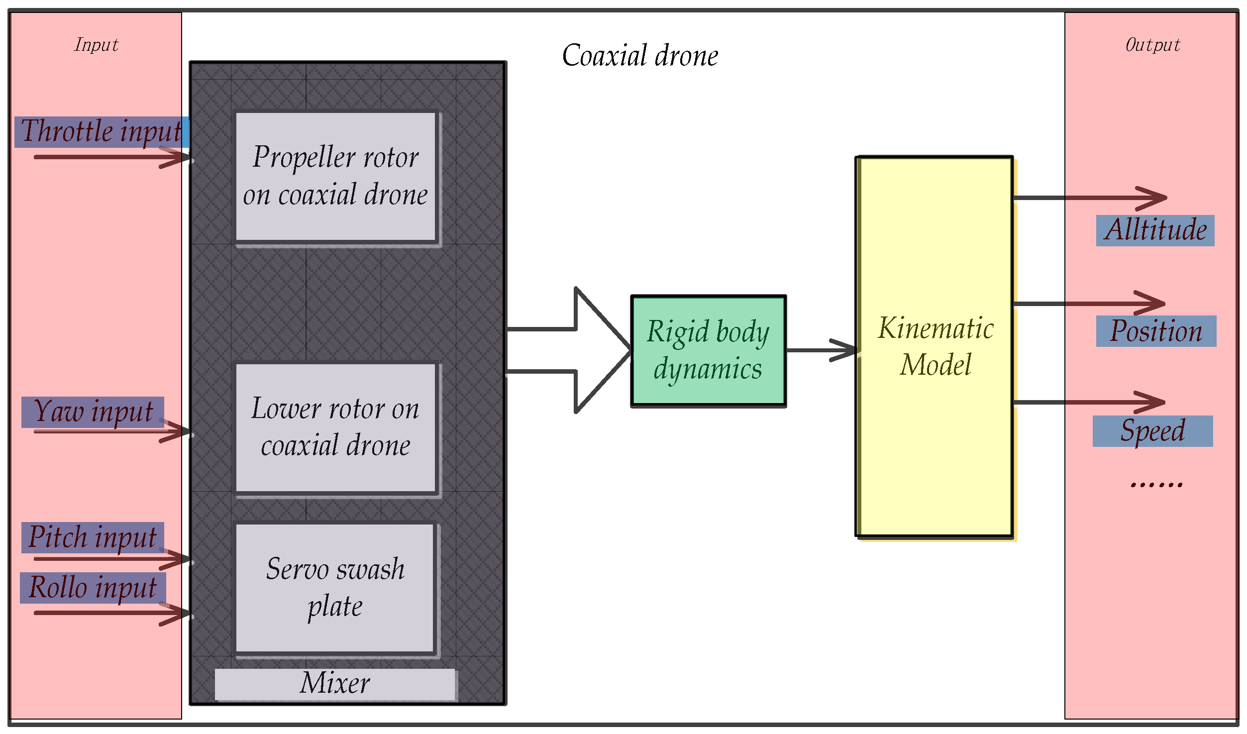
2.1. Dynamics Model of a Coaxial Twin-Rotor UAV
2.2. Kinematic Model of Coaxial Twin-Rotor UAV
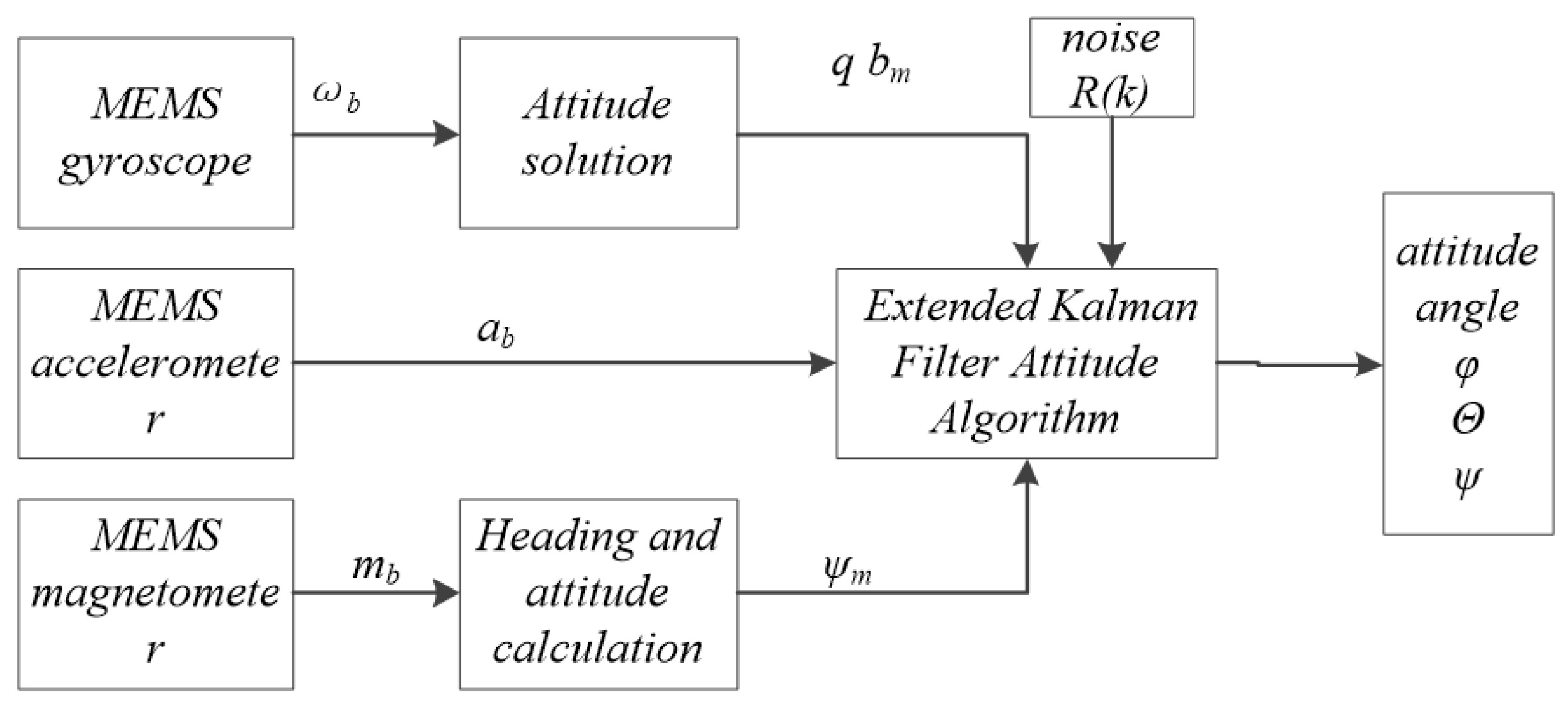
2.3. Attitude Estimation Methods
2.4. Filtering Model
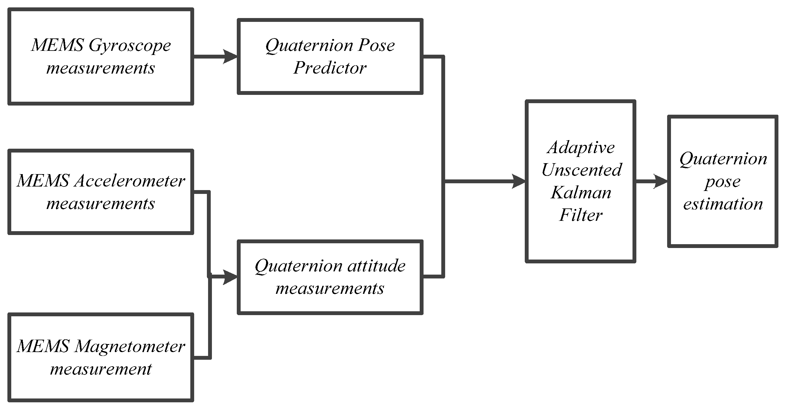
3. Adaptive UKF Filtering Algorithm
3.1. Adaptive Estimation of Measurement Noise
3.2. Filtering Algorithm
4. Attitude Control Test Methods
4.1. Test Scheme
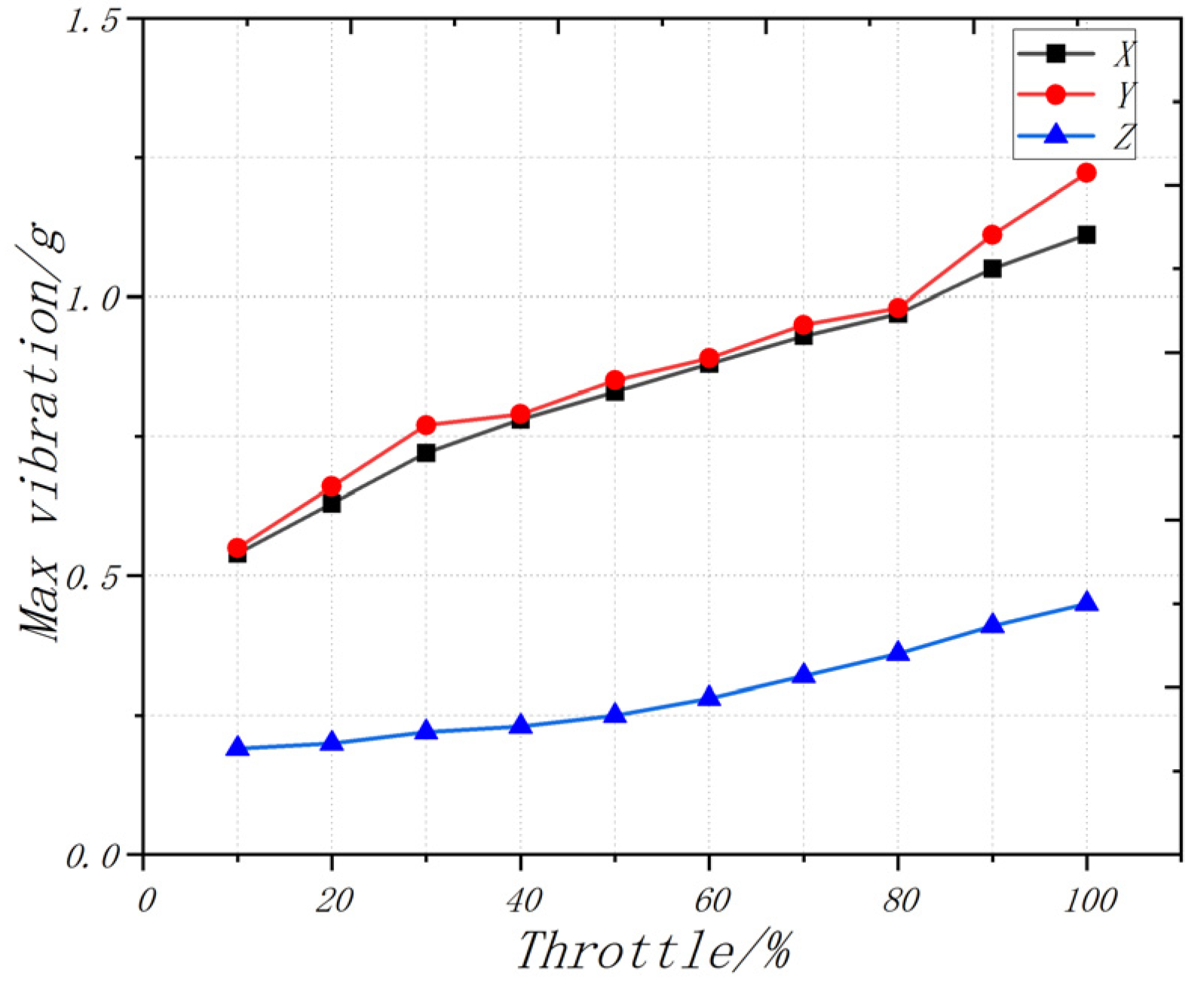
4.2. Vibration Test
4.3. The Static Test
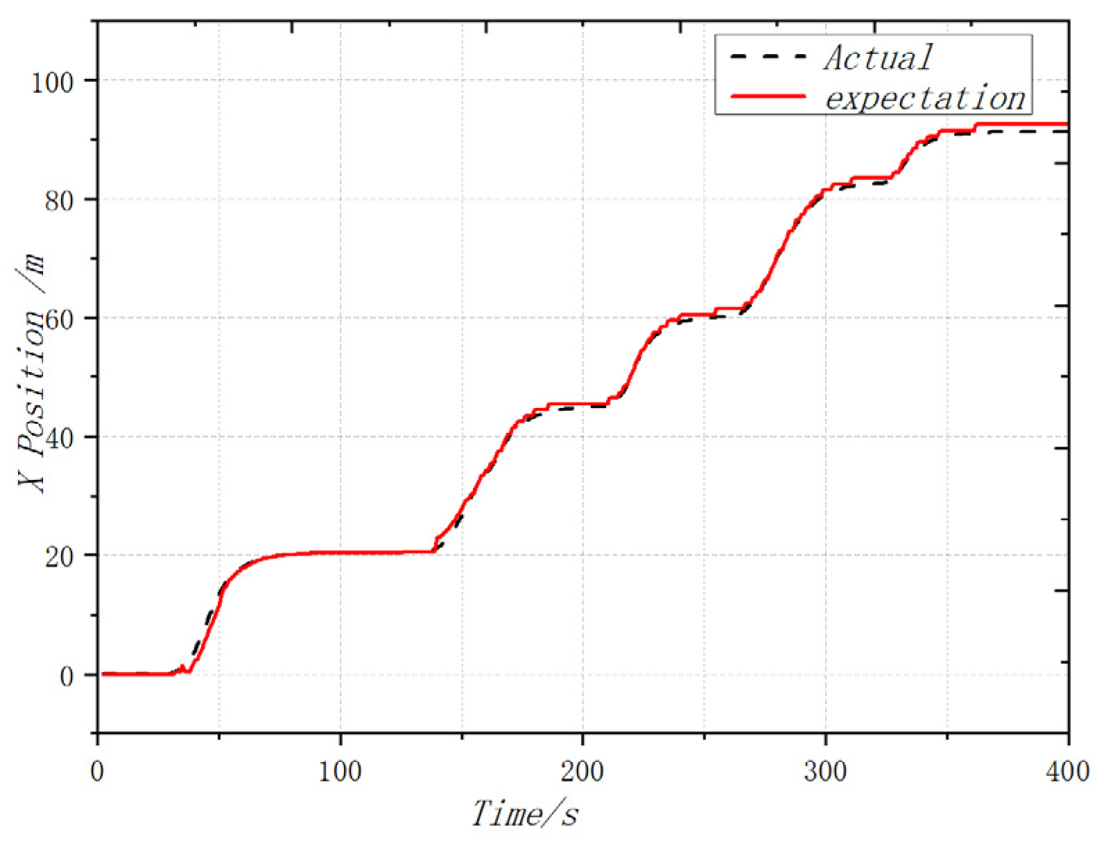
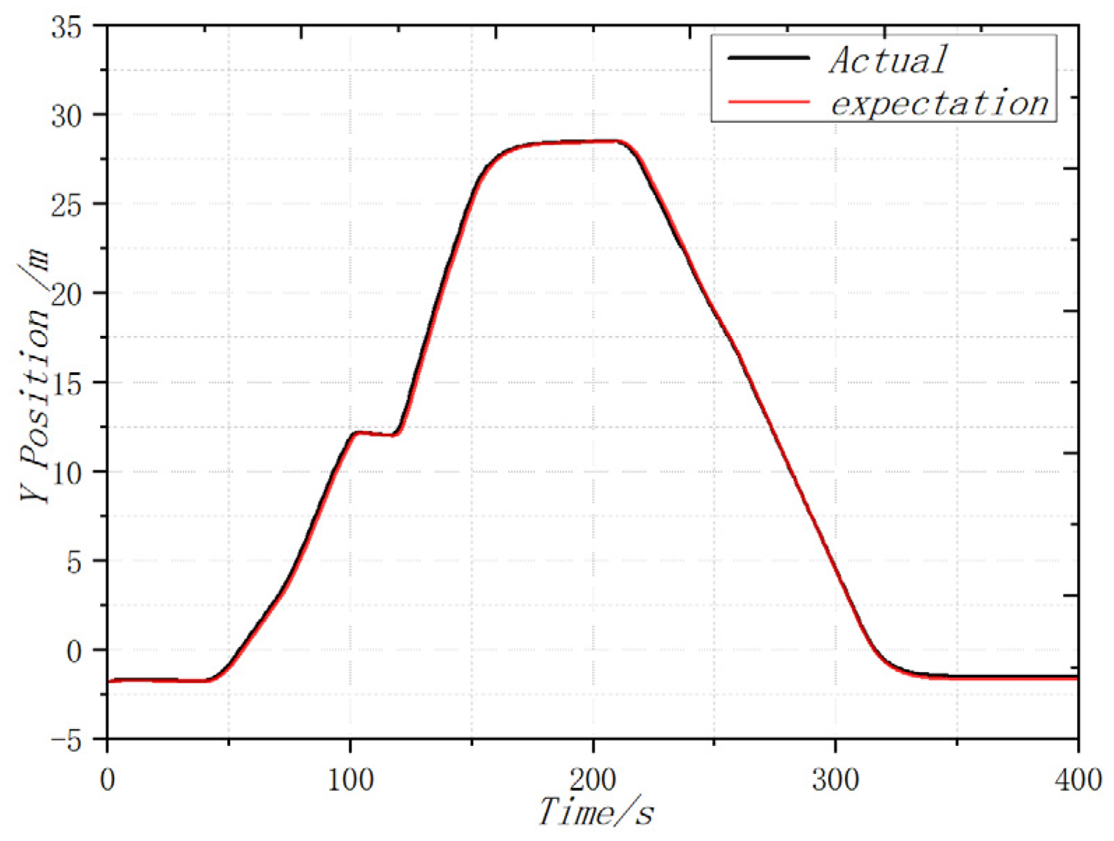
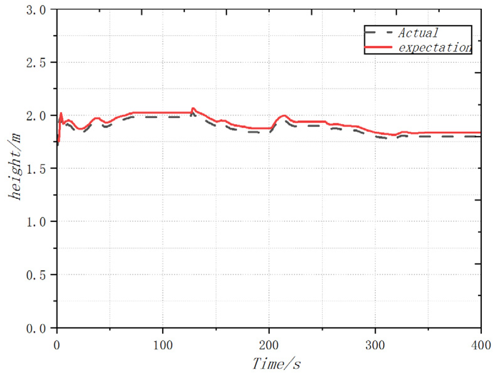
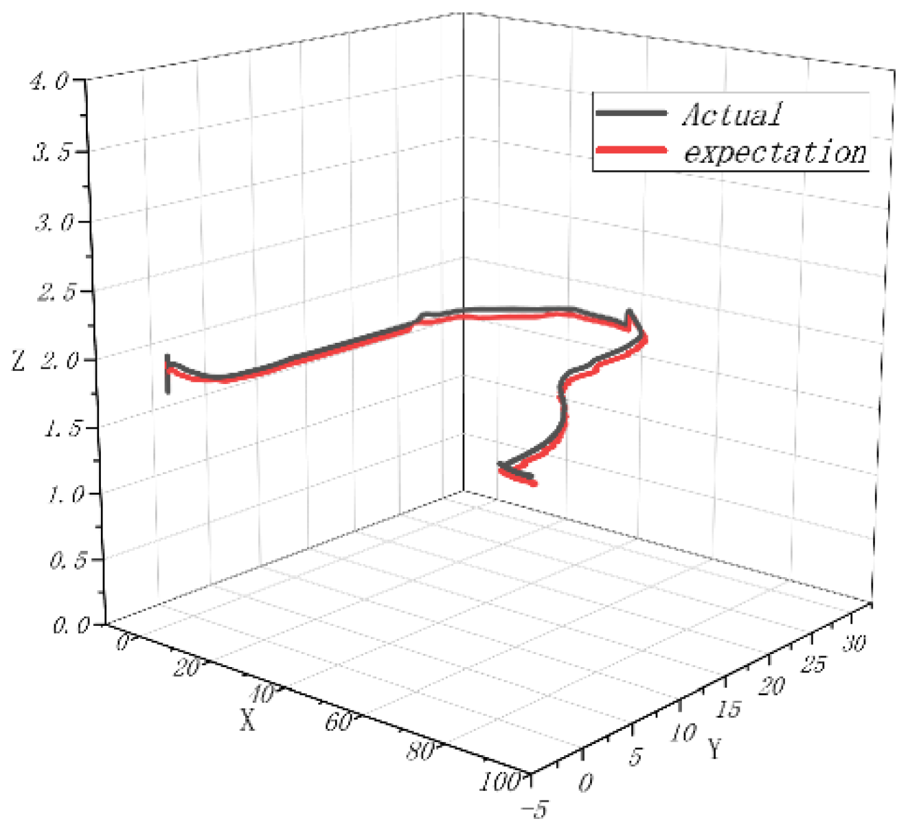
4.4. Dynamic Flight Experiment
5. Conclusions
Author Contributions
Funding
Institutional Review Board Statement
Informed Consent Statement
Conflicts of Interest
References
- Raja, V.; Solaiappan, S.K.; Rajendran, P.; Madasamy, S.K.; Jung, S. Conceptual Design and Multi-Disciplinary Computational Investigations of Multirotor Unmanned Aerial Vehicle for Environmental Applications. Appl. Sci. 2021, 11, 8364. [Google Scholar] [CrossRef]
- Zeghlache, S.; Mekki, H.; Bouguerra, A.; Djerioui, A. Actuator fault tolerant control using adaptive RBFNN fuzzy sliding mode controller for coaxial octorotor UAV. ISA Trans. 2018, 80, 267–278. [Google Scholar] [CrossRef] [PubMed]
- Park, H.-J.; Go, S.-C. Modeling and Control of a Hybrid Multi DOF Motor for a Tilted Rotating System. Energies 2022, 15, 7436. [Google Scholar] [CrossRef]
- Taherinezhad, M.; Ramirez-Serrano, A.; Abedini, A. Robust Trajectory-Tracking for a Bi-Copter Drone Using INDI: A Gain Tuning Multi-Objective Approach. Robotics 2022, 11, 86. [Google Scholar] [CrossRef]
- Xu, J.; Hao, Y.; Wang, J.; Li, L. The Control Algorithm and Experimentation of Coaxial Rotor Aircraft Trajectory Tracking Based on Backstepping Sliding Mode. Aerospace 2021, 8, 337. [Google Scholar] [CrossRef]
- Giljarhus, K.E.T.; Porcarelli, A.; Apeland, J. Investigation of Rotor Efficiency with Varying Rotor Pitch Angle for a Coaxial Drone. Drones 2022, 6, 91. [Google Scholar] [CrossRef]
- Mofid, O.; Mobayen, S.; Zhang, C.; Esakki, B. Desired tracking of delayed quadrotor UAV under model uncertainty and wind disturbance using adaptive super-twisting terminal sliding mode control. ISA Trans. 2022, 123, 455–471. [Google Scholar] [CrossRef] [PubMed]
- Prasad Rao, J.; Holzsager, J.E.; Maia, M.M.; Diez, J.F. Experimental Study into Optimal Configuration and Operation of Two-Four Rotor Coaxial Systems for eVTOL Vehicles. Aerospace 2022, 9, 452. [Google Scholar] [CrossRef]
- Candeloro, P.; Ragni, D.; Pagliaroli, T. Small-Scale Rotor Aeroacoustics for Drone Propulsion: A Review of Noise Sources and Control Strategies. Fluids 2022, 7, 279. [Google Scholar] [CrossRef]
- Al-Kaff, A.; García, F.; Martín, D.; De La Escalera, A.; Armingol, J.M. Obstacle Detection and Avoidance System Based on Monocular Camera and Size Expansion Algorithm for UAVs. Sensors 2017, 17, 1061. [Google Scholar] [CrossRef]
- Zhu, Y.; Zhou, J.; Yang, Y.; Liu, L.; Liu, F.; Kong, W. Rapid Target Detection of Fruit Trees Using UAV Imaging and Improved Light YOLOv4 Algorithm. Remote Sens. 2022, 14, 4324. [Google Scholar] [CrossRef]
- Panjwani, B.; Quinsard, C.; Przemysław, D.G.; Furseth, J. Virtual Modelling and Testing of the Single and Contra-Rotating Co-Axial Propeller. Drones 2020, 4, 42. [Google Scholar] [CrossRef]
- Sun, W.; Sun, P.; Wu, J. An Adaptive Fusion Attitude and Heading Measurement Method of MEMS/GNSS Based on Covariance Matching. Micromachines 2022, 13, 1787. [Google Scholar] [CrossRef] [PubMed]
- Alonge, F.; Cusumano, P.; D’Ippolito, F.; Garraffa, G.; Livreri, P.; Sferlazza, A. Localization in Structured Environments with UWB Devices without Acceleration Measurements, and Velocity Estimation Using a Kalman–Bucy Filter. Sensors 2022, 22, 6308. [Google Scholar] [CrossRef]
- Zhu, Y.; Liu, J.; Yu, R.; Mu, Z.; Huang, L.; Chen, J.; Chen, J. Attitude Solving Algorithm and FPGA Implementation of Four-Rotor UAV Based on Improved Mahony Complementary Filter. Sensors 2022, 22, 6411. [Google Scholar] [CrossRef] [PubMed]
- Yang, S.; Han, J.; Xia, L. Adaptive robust servo constraint tracking control for an underactuated quadrotor UAV with mismatched uncertainties. ISA Trans. 2020, 106, 12–30. [Google Scholar] [CrossRef] [PubMed]
- Zhou, H.; Mao, Q.; Song, Y.; Wu, A.; Hu, X. Analysis of Internal Angle Error of UAV LiDAR Based on Rotating Mirror Scanning. Remote Sens. 2022, 14, 5260. [Google Scholar] [CrossRef]
- Hentschke, M.; Pignaton de Freitas, E.; Hennig, C.H.; Girardi da Veiga, I.C. Evaluation of Altitude Sensors for a Crop Spraying Drone. Drones 2018, 2, 25. [Google Scholar] [CrossRef] [Green Version]
- Shukla, D.; Komerath, N. Multirotor Drone Aerodynamic Interaction Investigation. Drones 2018, 2, 43. [Google Scholar] [CrossRef] [Green Version]
- Matus-Vargas, A.; Rodriguez-Gomez, G.; Martinez-Carranza, J. A Monocular SLAM-based Controller for Multirotors with Sensor Faults under Ground Effect. Sensors 2019, 19, 4948. [Google Scholar] [CrossRef]
- Smithard, J.; Rajic, N.; Van der Velden, S.; Norman, P.; Rosalie, C.; Galea, S.; Mei, H.; Lin, B.; Giurgiutiu, V. An Advanced Multi-Sensor Acousto-Ultrasonic Structural Health Monitoring System: Development and Aerospace Demonstration. Materials 2017, 10, 832. [Google Scholar] [CrossRef] [PubMed] [Green Version]
- Becerra, V.M. Autonomous Control of Unmanned Aerial Vehicles. Electronics 2019, 8, 452. [Google Scholar] [CrossRef] [Green Version]
- Okulski, M.; Ławryńczuk, M. A Small UAV Optimized for Efficient Long-Range and VTOL Missions: An Experimental Tandem-Wing Quadplane Drone. Appl. Sci. 2022, 12, 7059. [Google Scholar] [CrossRef]
- Wang, Z.; Xu, M.; Liu, L.; Fang, C.; Sun, Y.; Chen, H. Optimal UAV Formation Tracking Control with Dynamic Leading Velocity and Network-Induced Delays. Entropy 2022, 24, 305. [Google Scholar] [CrossRef]
- Wengert, M.; Wijesingha, J.; Schulze-Brüninghoff, D.; Wachendorf, M.; Astor, T. Multisite and Multitemporal Grassland Yield Estimation Using UAV-Borne Hyperspectral Data. Remote Sens. 2022, 14, 2068. [Google Scholar] [CrossRef]
- Zhang, M.; Li, Q. A Compound Scheme Based on Improved ADRC and Nonlinear Compensation for Electromechanical Actuator. Actuators 2022, 11, 93. [Google Scholar] [CrossRef]
- Zhou, X.; Yu, X.; Guo, K.; Zhou, S.; Guo, L.; Zhang, Y.; Peng, X. Safety Flight Control Design of a Quadrotor UAV with Capability Analysis. IEEE Trans. Cybern. 2021. [Google Scholar] [CrossRef]
- Sun, C.; Liu, M.; Liu, C.; Feng, X.; Wu, H. An Industrial Quadrotor UAV Control Method Based on Fuzzy Adaptive Linear Active Disturbance Rejection Control. Electronics 2021, 10, 376. [Google Scholar] [CrossRef]
- Torresan, C.; Carotenuto, F.; Chiavetta, U.; Miglietta, F.; Zaldei, A.; Gioli, B. Individual Tree Crown Segmentation in Two-Layered Dense Mixed Forests from UAV LiDAR Data. Drones 2020, 4, 10. [Google Scholar] [CrossRef] [Green Version]
- Garcia-Nieto, S.; Velasco-Carrau, J.; Paredes-Valles, F.; Salcedo, J.V.; Simarro, R. Motion Equations and Attitude Control in the Vertical Flight of a VTOL Bi-Rotor UAV. Electronics 2019, 8, 208. [Google Scholar] [CrossRef]
- Tan, J.; Fan, Y.; Yan, P.; Wang, C.; Feng, H. Sliding Mode Fault Tolerant Control for Unmanned Aerial Vehicle with Sensor and Actuator Faults. Sensors 2019, 19, 643. [Google Scholar] [CrossRef] [PubMed] [Green Version]
- Sun, M.; Liu, J.; Wang, H. Robust fuzzy tracking control of a quad-rotor unmanned aerial vehicle based on sector linearization and interval matrix approaches. ISA Trans. 2018, 80, 336–349. [Google Scholar] [CrossRef] [PubMed]
- Mokhtari, M.R.; Cherki, B.; Braham, A.C. Disturbance observer based hierarchical control of coaxial-rotor UAV. ISA Trans. 2017, 67, 466–475. [Google Scholar] [CrossRef] [PubMed]
- Abedini, A.; Bataleblu, A.A.; Roshanian, J. Co-design Optimization of a Novel Multi-identity Drone Helicopter (MICOPTER). J. Intell. Robot. Syst. 2022, 106, 56. [Google Scholar] [CrossRef] [PubMed]


| UAV Test Platform | Platform Related Parameters |
|---|---|
| UAV | Coaxial twin rotor with diameter of 80 |
| UAV remote control | Fs-i6s |
| Battery | 1800 mah 35 c 4 s14.8 v |
| ESC | Platinum-25A-6S-V4 |
| Paddle | 19.5 cm ∗ 5 cm ∗ 0.5 cm |
| Electric motor | HKII-2213-14 3200kv |
| Steering engine | KST DS215MG V3.0 |
| Attitude sensor | Six axis wireless Bluetooth attitude sensor |
| Vibration sensor | Digital MEMS vibration sensor |
| Computer | CPU: Intel Core I7 8700, Memory: 8 GB (1333 MHz), Hard disk: solid state drive 240 G |
| Pressure sensor | DAYSENSOR DYLF-102 |
| Power | 15 V DC power supply |
Publisher’s Note: MDPI stays neutral with regard to jurisdictional claims in published maps and institutional affiliations. |
© 2022 by the authors. Licensee MDPI, Basel, Switzerland. This article is an open access article distributed under the terms and conditions of the Creative Commons Attribution (CC BY) license (https://creativecommons.org/licenses/by/4.0/).
Share and Cite
You, D.; Hao, Y.; Xu, J.; Yang, L. Research on Attitude Detection and Flight Experiment of Coaxial Twin-Rotor UAV. Sensors 2022, 22, 9572. https://doi.org/10.3390/s22249572
You D, Hao Y, Xu J, Yang L. Research on Attitude Detection and Flight Experiment of Coaxial Twin-Rotor UAV. Sensors. 2022; 22(24):9572. https://doi.org/10.3390/s22249572
Chicago/Turabian StyleYou, Deyi, Yongping Hao, Jiulong Xu, and Liyuan Yang. 2022. "Research on Attitude Detection and Flight Experiment of Coaxial Twin-Rotor UAV" Sensors 22, no. 24: 9572. https://doi.org/10.3390/s22249572