Article

Influence of Framework Material and Abutment Configuration on Fatigue Performance in Dental Implant Systems: A Finite Element Analysis

by
Meryem Erdoğdu
1,*,
Mehmet Gökberkkaan Demirel
1,
Reza Mohammadi
2,
Neslihan Güntekin
1 and
Masoud Ghanbarzadeh Chaleshtori
3
1
Department of Prosthodontics, Faculty of Dentistry, Necmettin Erbakan University, 42090 Konya, Türkiye
2
Faculty of Dentistry, Necmettin Erbakan University, 42090 Konya, Türkiye
3
Department of Mechanical Engineering, Buali University of Hamedan, Hamedan 65178-38695, Iran
*
Author to whom correspondence should be addressed.
Medicina 2024, 60(9), 1463; https://doi.org/10.3390/medicina60091463
Submission received: 4 July 2024 / Revised: 17 August 2024 / Accepted: 27 August 2024 / Published: 6 September 2024
(This article belongs to the Special Issue Recent Advances in Periodontics and Dental Implantology: Part II)

Abstract

:
Background and Objectives: This study uses finite element analysis to evaluate the impact of abutment angulation, types, and framework materials on the stress distribution and fatigue performance of dental implant systems. Materials and Methods: Three-dimensional models of maxillary three-unit fixed implant-supported prostheses were analyzed. Abutments with different angles and types were used. Two different framework materials were used. Conducted on implants, a force of 150 N was applied obliquely, directed from the palatal to the buccal aspect, at a specific angle of 30 degrees. The distribution of stress and fatigue performance were then assessed, considering the types of restoration frameworks used and the angles of the abutments in three distinct locations. The simulation aspect of the research was carried out utilizing Abaqus Software (ABAQUS 2020, Dassault Systems Simulation Corp., Johnston, RT, USA). Results: In all models, fatigue strengths in the premolar region were higher than in the molar region. Maximum stress levels were seen in models with angled implants. In almost all models with the zirconia framework, fatigue performance was slightly lower. Conclusions: According to the findings of this study, it was concluded that the use of metal-framework multi-unit restorations with minimum angulation has significant positive effects on the biomechanics and long-term success of implant treatments.

1. Introduction

Dental implant abutments play a crucial role in the success and longevity of implant-supported prostheses. The type and angle of abutments have been shown to significantly impact stress distribution, mechanical stability, and peri-implant tissue health [1,2,3]. The angle of the dental implants is a critical factor that influences their placement accuracy, biomechanical behavior, and long-term success [1,4,5]. Angled implants offer both advantages and disadvantages in various medical and dental applications. One significant advantage of angled implants is their ability to compensate for non-ideal implant positions, allowing for better alignment with the natural anatomy and improving functional prosthesis outcomes [6]. By tilting the distal implant, a more posterior position can be achieved, enhancing implant anchorage by utilizing the cortical bone of the sinus and nasal fossa [7]. This positioning allows for longer implants in available bone, increasing the bone–implant contact area and primary anchorage [8]. Biomechanically, tilted implants can improve stability by increasing contact with cortical bone, leading to enhanced stability [9]. Additionally, the use of tilted implants can increase the anterior–posterior spread, contributing to a favorable pattern of bone resorption and stress distribution, especially when splinted with a rigid superstructure [10]. Research has shown that angled implants, when used in conjunction with a short cantilever, can decrease stress on peri-implant cortical bone, further enhancing the long-term success of the implant treatment [10]. Furthermore, the use of tilted implants can reduce costs by avoiding the need for angulated abutments, benefiting both clinicians and patients economically. However, angled implants also come with drawbacks. In terms of prosthetic considerations, tilted implants can increase stress on bone tissue and prosthetic screws, which should be carefully managed to ensure long-term success (Almeida et al., 2022). Another major disadvantage is the potential transfer of unfavorable forces to the implant or bone, which can compromise treatment prognosis by causing stress concentrations and damage to the peri-implant bone [11]. Moreover, concern is the increased cost, manufacturing complexity, and maintenance requirements associated with using angled abutments or bars to compensate for implant angulation [12]. Tao et al. [5] have highlighted that deviations in dental implant angles affect the success of the procedure and showed that implants with smaller deviations lead to better outcomes. Similarly, Mosharraf et al. [1] highlighted the impact of abutment angles on stress distribution in implant-supported prostheses, emphasizing the importance of considering angles in the design and placement of dental implants. Furthermore, Kitagawa et al. [13] investigated the influence of taper angle on the dynamic behavior of taper joint dental implants, emphasizing the importance of considering the angle in the design and analysis of implant systems. Other studies have utilized finite element analysis to investigate the effects of angle implantation cases on implant success, highlighting the biomechanical implications of implant angles [14,15]. These findings underscore the significance of dental implant angles in ensuring optimal biomechanical performance and long-term success. Additionally, a higher probability of failure and increased peri-implant marginal bone loss in dental implants connected to angled abutments compared to straight abutments have been observed, indicating the potential risks associated with certain implant angles [16]. The precise compensation of dental implant angles with the appropriate abutment type is crucial for the success of implant-supported prostheses. The angulation of implants and the type of abutment used can significantly impact the retention and stress distribution in the prosthesis. In this context, Frantz et al. [17] conducted an in vitro study to test the retention of overdenture attachment systems with different implant angulations and abutment types, highlighting the importance of considering the angle of the implants and the type of abutment for optimal retention. Additionally, Mosharraf et al. [1] performed a finite element analysis to evaluate the effect of abutment angulation on stress distribution in implant-supported prostheses, emphasizing the significance of considering different abutment angles for stress management.
Additionally, the choice of abutment material, such as ceramic or metallic, can influence peri-implant clinical parameters and tissue adaptation [18,19]. The choice of abutment material plays a crucial role in the overall outcome. Accordingly, a study investigated the effect of zirconia and alumina implant abutments on the light reflection of supporting soft tissues, indicating the importance of considering the material of the abutment for aesthetic and biological reasons [20]. Moreover, another study conducted a three-dimensional finite element analysis to assess the influence of prosthesis type and material on stress distribution in bone around implants; they emphasize the need to consider the material properties of the abutment for optimal stress distribution [21].
When deciding between a cemented or screwed abutment for an implant-supported prosthesis, several factors need to be considered. Cemented abutments offer advantages such as providing a more passive fit due to compensating for any distortion during framework casting [22]. However, it is crucial to note that the screw access channel in the abutment is commonly occluded prior to cementation, which can lead to challenges in case of future maintenance or repairs [23]. On the other hand, screwed abutments can help prevent issues like abutment screw loosening, which is a common problem with implant-supported prostheses [24,25]. Additionally, the choice of cement plays a significant role in the retention of restorations, with more retentive cements potentially causing damage to the implant fixture, abutment, or prosthesis if aggressive techniques are used for removal [26]. Moreover, the design of the abutment, including factors like height, taper, and margin level, can influence the retention and amount of residual cement in cement-retained restorations [27,28]. Studies have shown that the margin level of the abutment can impact the occurrence of residual cement, with subgingival margins leading to higher rates of cement residues [27]. Furthermore, the use of resin cements and different abutment types can affect the aesthetics of implant-supported restorations [29]. When considering abutment type for existing angulation in dental implant restorations, it is essential to weigh the advantages and disadvantages of screwed versus cemented abutments. Screwed abutments offer retrievability and ease of maintenance but they may be associated with higher rates of screw loosening, especially with increased abutment angulation [30,31]. On the other hand, cemented abutments provide better resistance to fluid and bacterial permeability, potentially leading to improved long-term outcomes [32]. However, it is crucial to note that the choice between screw-retained and cement-retained restorations should also consider factors such as aesthetics and occlusal integrity [33]. Studies have shown that abutment angulation plays a significant role in the stability and performance of implant restorations. Higher angulations have been linked to increased screw loosening and decreased mechanical strength, potentially leading to higher failure rates [31]. Additionally, the type of implant–abutment connection and screw length can influence preload retention and overall stability [34]. Angulated screw channel (ASC) abutments have been developed to allow for screw-retained restorations even in cases of non-ideal implant positioning, as long as the angulation correction needed is within a certain range [35]. As a result of these studies, it can be concluded that screwed abutments, especially those with angulation, offer benefits in terms of retention, stability, and adaptability to challenging anatomical situations. While some studies highlight potential issues like increased marginal bone loss with angulated abutments, the overall advantages of using screwed abutments in cases with angulation seem to outweigh the drawbacks. The effects of implant restoration materials on stress distribution have been extensively studied through various research articles. The choice of restoration material compositions, such as coping and veneering porcelain, has been shown to significantly affect stress distribution in implant-supported prostheses [1]. Additionally, the moduli of elasticity of implant restorative materials have been found to have similar effects on stress distribution through dental implants and their surrounding bone [36]. Furthermore, the use of composite resin materials as abutment or restoration materials has been suggested to resolve the dilemma of abutment rigidity under mechanical stress, indicating their potential to manage stress distribution in implant-supported restorations [37,38]. The influence of various occlusal materials on stress transfer to implant-supported prostheses and supporting bone has also been investigated. Studies have reported that the choice of occlusal surface material, such as acrylic-based materials, metal alloys, and ceramics, can impact stress distribution [39]. Moreover, the use of indirect composite materials with elastic properties as veneering materials for implant-supported prostheses has been suggested to improve the shock-absorbing capacity and reduce impact force and stress distribution on implants [40]. Finite element analysis (FEA) has been widely employed to simulate the stress distribution in dental implants and alveolar bone, providing valuable insights into the mechanical behavior of different restorative materials [41]. Additionally, the effect of prosthetic materials on crestal bone loss has been highlighted, with prosthetic materials found to have a greater effect on crestal bone loss than implant systems [42]. Implant restoration material compositions, specifically PFBM and PFBZ, have a significant impact on stress distribution within the prosthetic structures. Studies have shown that the choice of materials influences the stress distribution in implant-supported prostheses. For instance, Sertgöz Sevimay et al. [43] found that the combination of cobalt–chromium for the framework and porcelain for the occlusal surface resulted in optimal stress distribution in implant-supported fixed prostheses. Additionally, Bakitian et al. [44] reported that layered zirconia fixed dental prostheses (FDPs) are associated with more chipping of the veneering porcelain compared to PFBM FDPs, indicating a difference in stress distribution between these materials. Moreover, the literature suggests that the composition of the restoration materials impacts the fracture rates of the prostheses. Agustín-Panadero et al. [45] highlighted that PFBZ restorations have a fracture rate ranging between 6% and 15% over a 3- to 5-year period, while ceramo-metallic restorations exhibit fracture rates between 4% and 10% over 10 years. This indicates that the choice of materials, such as PFBZ restorations, can influence the longevity and success of the prostheses. In conclusion, the selection of implant restoration material compositions, whether PFBM or PFBZ, plays a crucial role in determining stress distribution within prosthetic structures. Understanding the impact of these material compositions on stress distribution is essential for designing durable and long-lasting implant-supported prostheses.
In conclusion, when dealing with existing angulation in dental implant cases, the choice between screwed and cemented abutments and also the choice between PFBM or PFBZ should be made based on a comprehensive assessment of factors such as maintenance ease, bacterial permeability, mechanical stability, and aesthetic considerations. It is crucial to consider the specific clinical scenario, including the degree of angulation, to determine the most suitable abutment type and framework material for each individual case. Understanding these factors is crucial for improving the longevity and success of dental implants. In accordance with various findings from prior research on the extent and pattern of fatigue performance on implants and bone across varying abutment angulations and prosthesis materials, further investigations are warranted in this area. Despite advances in dental implant technology, while the existing literature offers valuable insights into the individual effects of abutment type, material framework, and angulations on implant biomechanics, there is a clear gap in the research of comprehensively examining the combined impact of these factors. Therefore, the primary objective of this study was to evaluate the impact of abutment angulation, type, and diverse materials utilized for implant-supported prostheses on the stress distribution and fatigue performance within the implant and adjacent tissues through FEA. This study’s null hypothesis posited that abutment angulation and the use of different framework materials for implant-supported prostheses would not influence the fatigue performance.

2. Materials and Methods

2.1. Preparation of Specimens

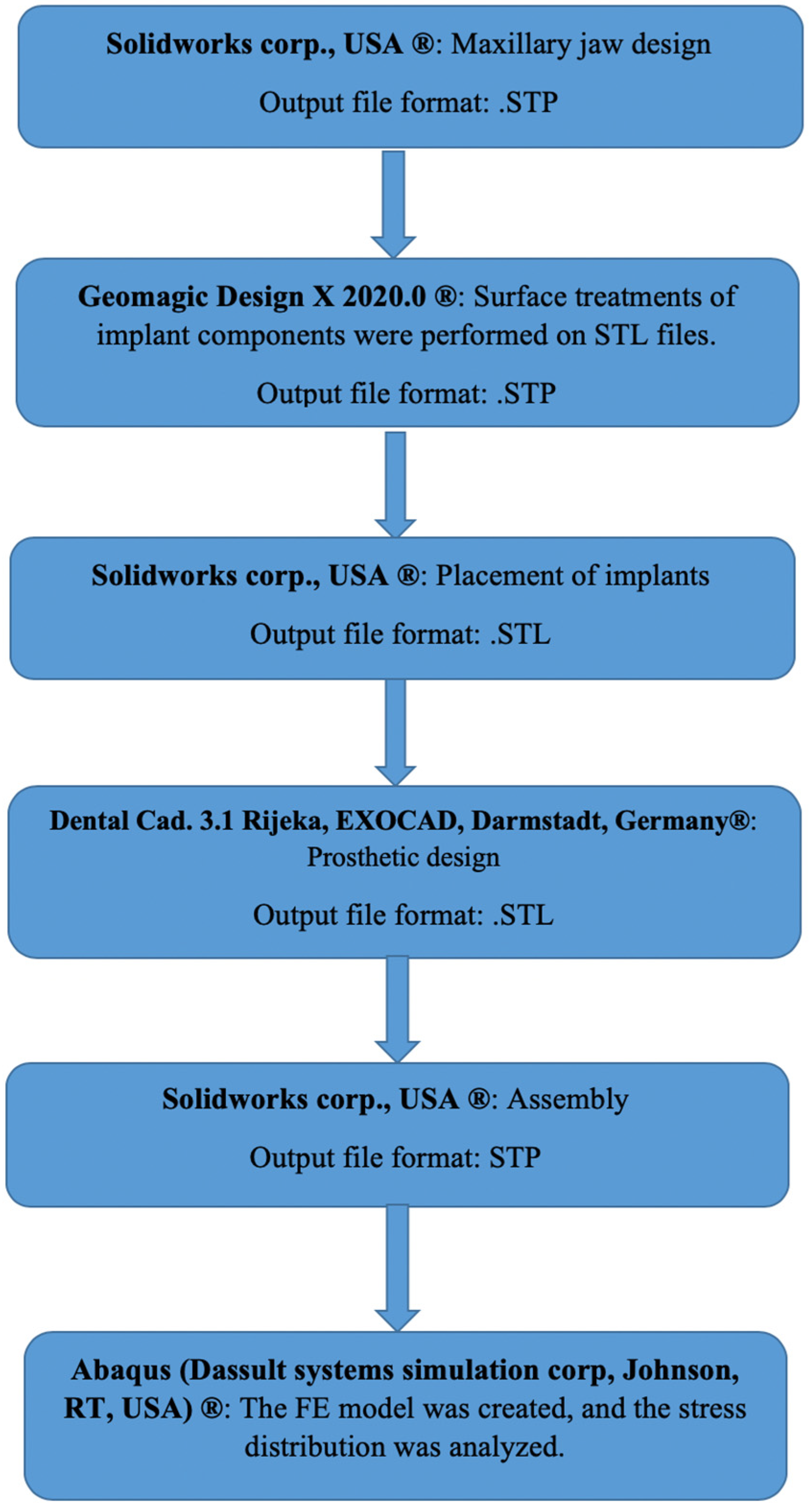
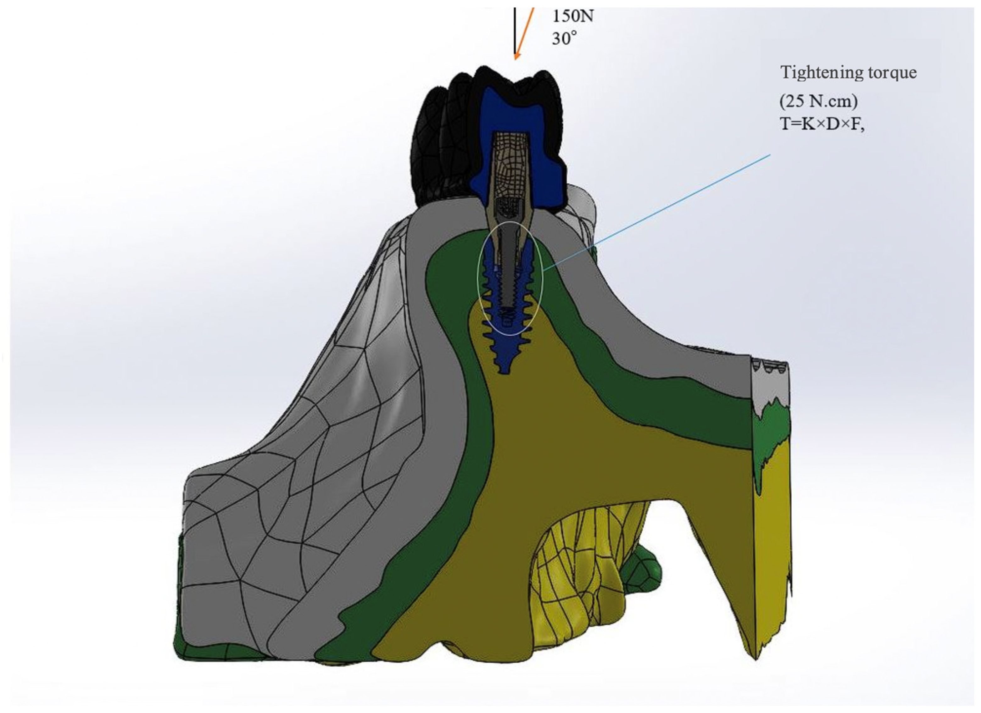
In this study, multi-unit and resin-cemented restoration designs of Bil implant company (İstanbul, Türkiye) were used. Restorations with two different framework materials (porcelain fused to base metal (PFBM) and porcelain fused to base zirconia (PFBZ)) were used. Straight (3LSRAGH2NP, new ⌀3.7 mm implant L 10 mm), 15° (Abutment screw NP, BLSR156H2ANP, new ⌀3.7 mm implant L 10 mm), and 30° (Abutment screw NP, BLSR306H2ANP, new ⌀3.7 mm implant L 10 mm) abutments of the company were used for the multi-unit design. Additionally, for the resin-cemented type, straight (Abutment screw NP, new ⌀3.7 mm implant L 10 mm, PAD35GH2AH55NP), 15° (Abutment screw NP, new ⌀3.7 mm implant L 10 mm, PAA156H2AH7NP), and 25° (Abutment screw NP, new ⌀3.7 mm implant L 10 mm, PAA25GH2AH7NP) abutments were used. The groups used in the analysis are as follows: multi-unit 0-degree metal framework (Mu0M); multi-unit 15-degree metal framework (mu15M); multi-unit 30-degree metal framework (Mu30M); cemented 0-degree metal framework (C0M); cemented 15-degree metal framework (C15M); cemented 25-degree metal framework (C25M); multi-unit 0-degree zirconia framework (Mu0Z); multi-unit 15-degree zirconia framework (Mu15Z); multi-unit 30-degree zirconia framework (Mu30Z); cemented 0-degree zirconia framework (C0Z); cemented 15-degree zirconia framework (C15Z); and cemented 25-degree zirconia framework (C25Z). For the preparation of the specimens, a model was designed to mimic the maxillary jaw bone (mucosa, trabecular, and cortical bone) of an edentulous patient. The assembly module of the Solidworks 2013 (Solidworks Corp., Waltham, MA, USA) program was used for this design. In the design, the region of tooth 15 was considered missing and the bridge planning was aimed to be realized with implant placement in the region of teeth 14 and 16. Into the STP file that was obtained, the implants were positioned according to the information received from Bil implant company. In the insert section, the indent command in the feature section was used to create the cavity of the implant in the bone, and STL files were obtained for the prosthesis design. Following that, the designs of the prostheses were made using the Exocad program (Dental Cad. 3.1 Rijeka, EXOCAD, Darmstadt, Germany). These STL files were transferred to the Geomagic Design X program (Geomagic Design X 2020.0) and STP files were obtained after adjustments such as smoothing. The prostheses were then placed on the implants on the model. In addition, for resin-cemented restorations, a cement gap of 40 μm was closed with resin cement. The final version of the obtained models was saved as an STP file and transferred to the Abaqus program (ABAQUS 2020 Dassault Systems Simulation Corp., Johnston, RT, USA) for FEA (Figure 1). In the Abaqus program, the properties of the materials were first transferred to the program in the property section, and the analysis type was defined as static, general, and direct cyclic in the step section. In the direct cyclic section, the number of cycles was entered as 1000. Then, in the interaction section, the contacts (except for the contact between the screw and the implant) were transferred to the program as a tie and the loading and boundary conditions were performed in the load section. Then, the mesh process was performed in the mesh section of the Abaqus program (Figure 2). The total number of nodes and elements is shown in Table 1. Material properties were defined for all components to be included in the study (Table 2). The chosen properties reflect the typical mechanical behavior of every material as documented in previous studies, as also mentioned in Table 2. The connections between the components were provided in the interaction area. The connections simulated as a tie to simulate the osseointegration property were as follows: framework and porcelain, composite and prosthesis, bone and mucosa, and implant and bone. The connection between the screw parts was simulated by giving torque properties.

2.2. Estimating the Stress Distribution

A load of 150 N was applied to the occlusal table (an inclination from palatal to buccal, at an angle of 30 degrees). At this stage, the maxillary bone was encastred, which means that the maxillary bone was restricted from movement and rotation in all directions. In this study, it was assumed that the implants were completely osseointegrated with the bone and that the implant components did not show any movement on the implant surface. In order to define the quality of integration, a frictional contact type was applied between the abutment, fixture, and abutment screw interface. The frictional coefficient was set to 0.3.
The equation for the screw torque moment is as follows:
T = K × D × F ,
where T corresponds to the screw torque moment (Ncm); D is the screw diameter (m); F is the screw preload (N); and K is the screw factor or torque coefficient (usually with a value of 0.2). Using the above equation, the screw preload value can be calculated if a tightening moment is applied to the abutment screw. In this study, using a tightening moment of 25 Ncm, the screw preload value was calculated as 781 N (Figure 3). After this process, stress values were obtained. Stress values are reported as von Mises Stress values (vMS).

2.3. Estimating the Fatigue Performance

For long-term implant success, maximum or endless fatigue performance needs to be achieved. As an evaluation method, physical testing or fatigue analysis can be applied. In this study, the following equations were used through FE modeling to estimate the fatigue performance of implants.
γ 2 + ε N 2 = 1.65 σ f σ N , m E ( 2 N f ) b + 1.75 ε f ( 2 N f ) c .
where σN,m corresponds to the normal stress on the critical plane; 2Nf is the number of reversals to crack initiation; γ/2 is the shear strain amplitude; ΔεN is the normal strain on the critical plane; σ f is the fatigue strength coefficient; ε f is the normal fatigue ductility coefficient; E is the elastic modulus; c is the fatigue ductility exponent; and b is the fatigue strength exponent. The fatigue ductility exponent and coefficient are derived from the Coffin–Manson law [51].
ε P = ε f ( 2 N f ) c .
where ε P   A represents the plastic strain.
The fatigue strength exponent and coefficient come from Basquin’s law:
ε e = σ a E = σ f E ( 2 N f ) b .
σ a = σ 2 = ( σ m a x σ m i n ) 2 .
where ε e is equivalent to the elastic component of the cyclic strain amplitude; ve σ a is equivalent to the cyclic stress amplitude.
The material properties were approximated using Seeger’s method by rescaling the conventional monotonic ultimate tensile stress (UTS) [52].
Table 3 shows the values of all the relative parameters for titanium according to Seeger’s method.

3. Results

3.1. Stress Distribution

3.1.1. Stress Values on the Implant

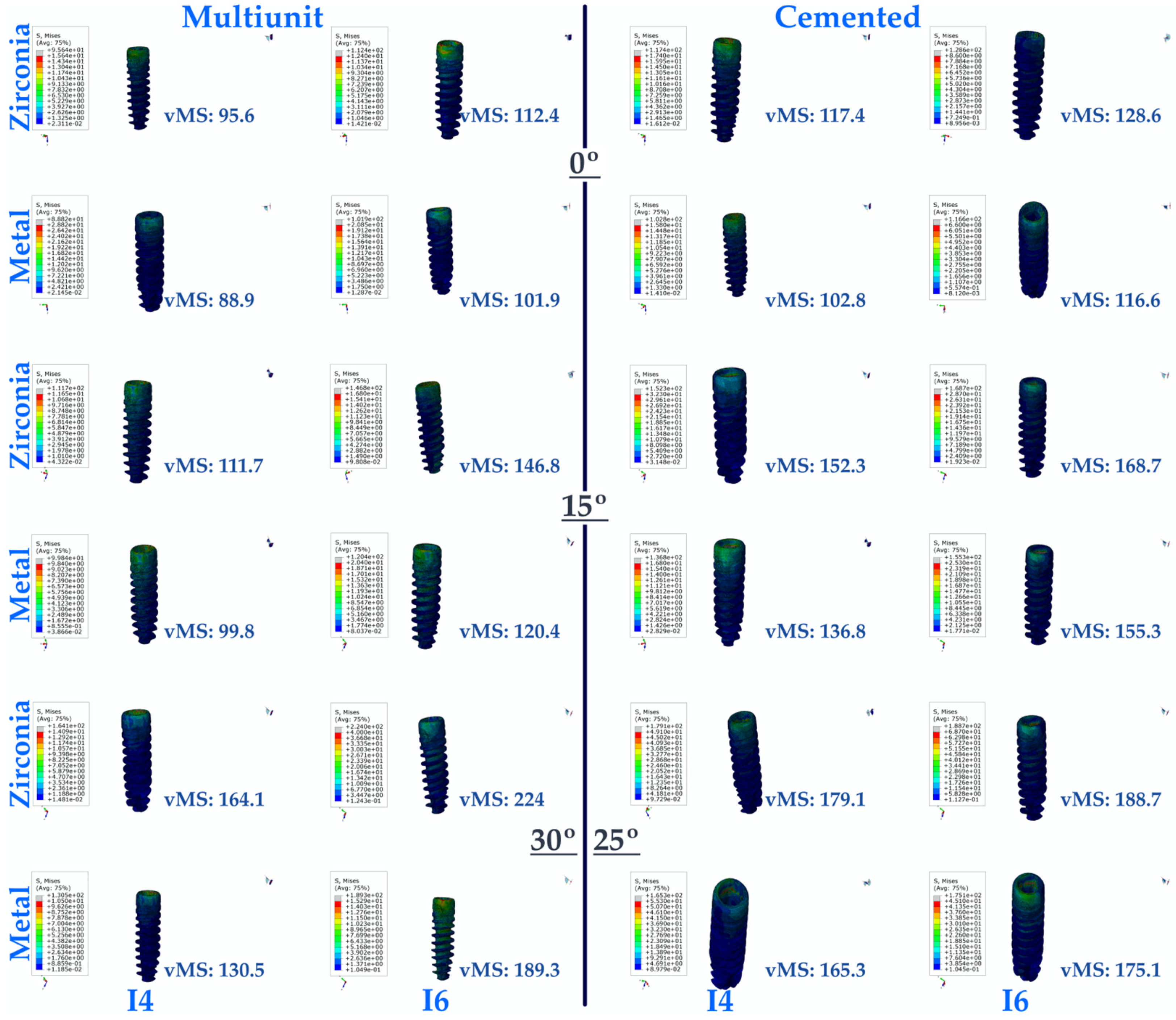
As a result of this study, the lowest vMS values were generally seen in multi-unit restorations for implants in the premolar region. The lowest vMS was found in Mu0M. In resin-cemented restorations, where the vMS was higher than in multi-unit restorations, the highest vMS was seen in C25Z. For both types of abutments (multi-unit and resin cemented), vMS values increase with increasing angulation. In addition, PFBZ obtained higher vMS values for both restorations.
In the implants in the molar region, the lowest vMS was observed in Mu0M. The highest vMS was obtained in Mu30Z. In both types of restorations (multi-unit and resin cemented), regardless of whether PFBM or PFBZ was used, vMS increased with increasing angulation. For implants in the molar region, lower vMS values are observed up to 15 degrees of angulation in screw-retained restorations, regardless of the framework material. When the angulation increases to 30 degrees in multi-unit restorations, higher vMS values are observed compared to resin-cemented restorations with an angulation of 25 degrees. Similar to the premolar region, PFBZ has higher vMS for both restorations.
In general, it was found that the vMS applied to implants in the premolar region was less distributed compared to implants in the molar region (Figure 4).

3.1.2. Stress Values on the Abutment

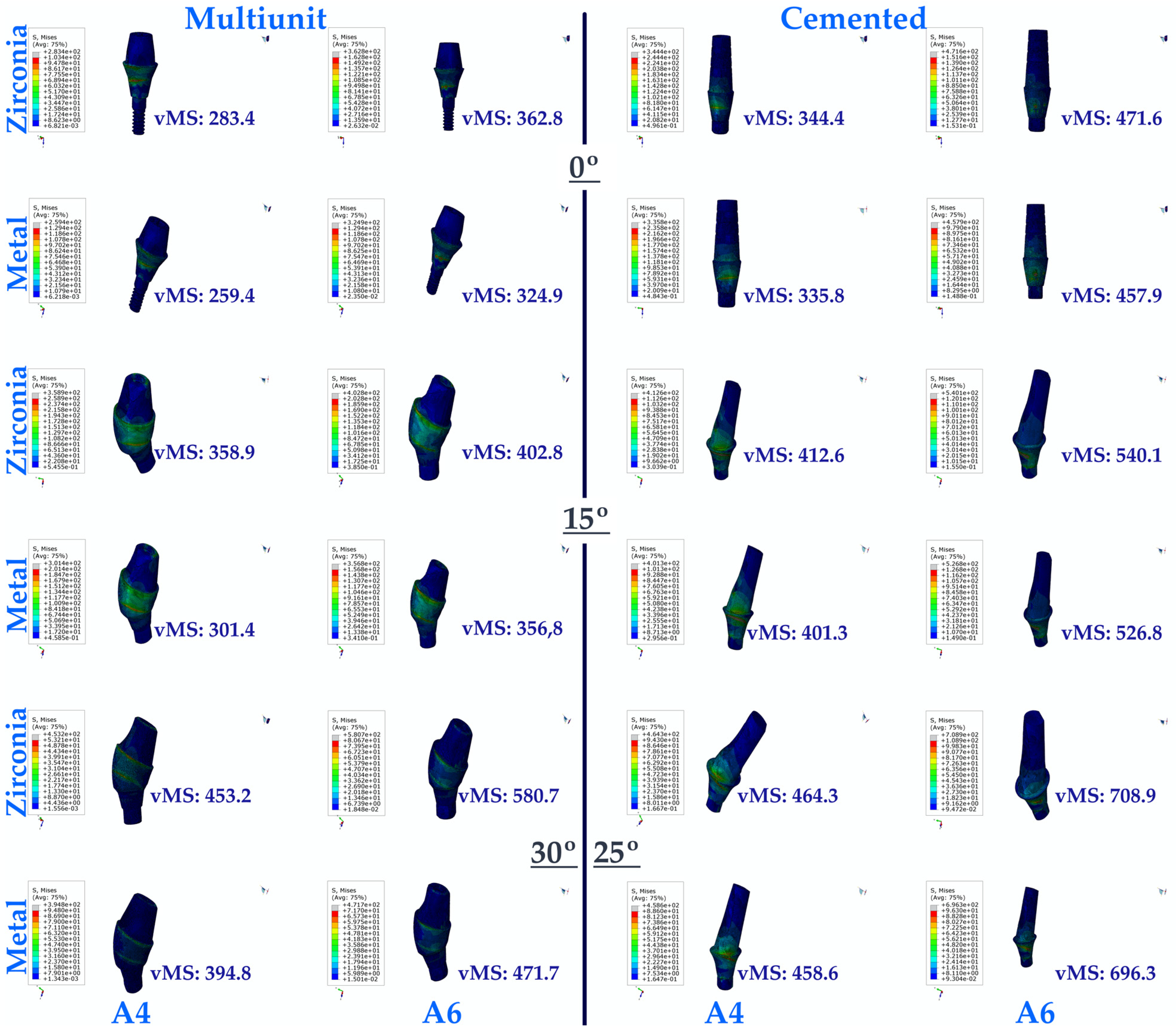
The lowest vMS seen in the abutments in the premolar region was seen in Mu0M, while the highest vMS was seen in C25Z. When both resin-cemented and multi-unit restorations were evaluated separately, it was observed that the vMS on the abutments increased with increasing angulation. In addition, the highest vMS values were obtained in restorations with the highest angulation. When the vMS on the abutments in the premolar region was analyzed, a higher vMS was observed in restorations with PFBZ in direct proportion to the increase in angulation, while this distribution was lower in restorations with PFBM. It was observed that the vMS on the abutments in the premolar region was lower when multi-unit restorations were used compared to resin-cemented restorations.
Similar to the abutments in the premolar region, the lowest vMS in the abutments in the molar region was observed in Mu0M, while the highest vMS was found in C25Z. In addition, the highest vMS values were obtained in restorations with the highest angulation. Furthermore, lower vMS values were obtained in multi-unit restorations compared to resin-cemented restorations regardless of the framework material. Again, PFBZ gave higher vMS than PFBM in every group.
Among the vMS observed in the abutments, the lowest vMS values were observed in the premolar region, similar to the vMS observed in the implants (Figure 5).

3.1.3. Stress Values on the Cortical Bone

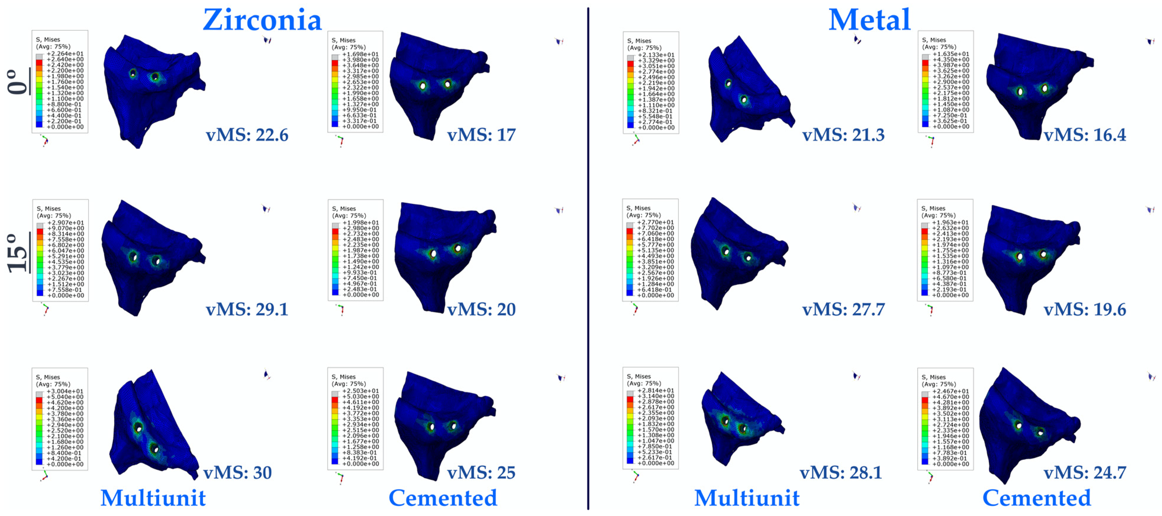
As a result of this study, the effects of the applied stress on the cortical bone were also examined. The lowest vMS was observed in C0M, while the highest vMS was observed in Mu30Z. In both multi-unit and resin-cemented restorations, regardless of the framework material, it was found that vMS increased with increasing angulation. In addition, vMS values in bone were lower in resin-cemented restorations, while higher vMS values were obtained in multi-unit restorations. In addition, all PFBZ restorations calculated higher vMS values than PFBM restorations (Figure 6).

3.1.4. Stress Values on the Framework

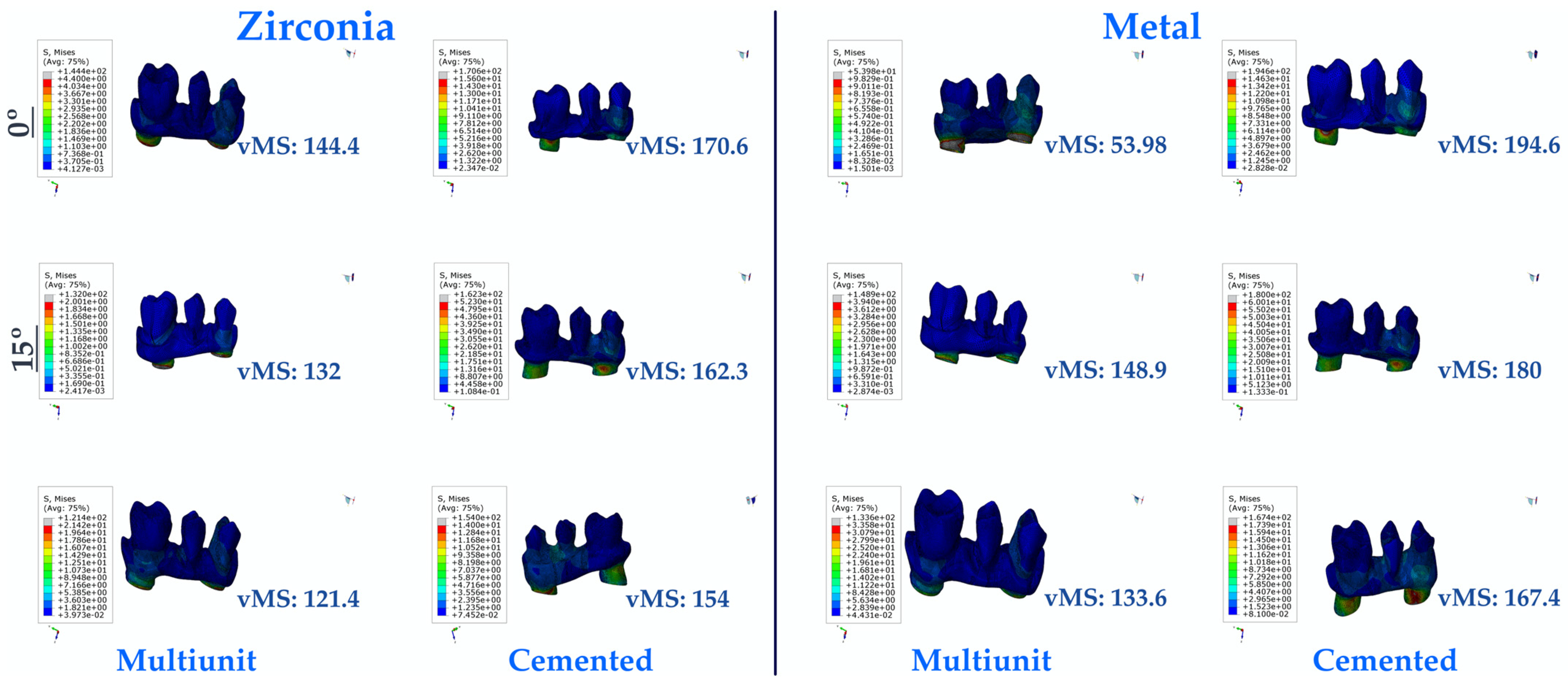
When the prosthetic frameworks were analyzed, the lowest vMS was found in Mu30Z. The highest vMS was observed in C0M. In both types of restorations, vMS decreased with increasing angulation, independent of the framework material. Multi-unit restorations were found to have lower vMS than resin-cemented restorations. In addition, in both types of restorations, PFBM and PFBZ restorations caused a decrease in vMS inversely proportional to the increase in angulation, while PFBM restorations gave higher vMS values than PFBZ restorations (Figure 7).

3.1.5. Stress Values on the Abutment Screw

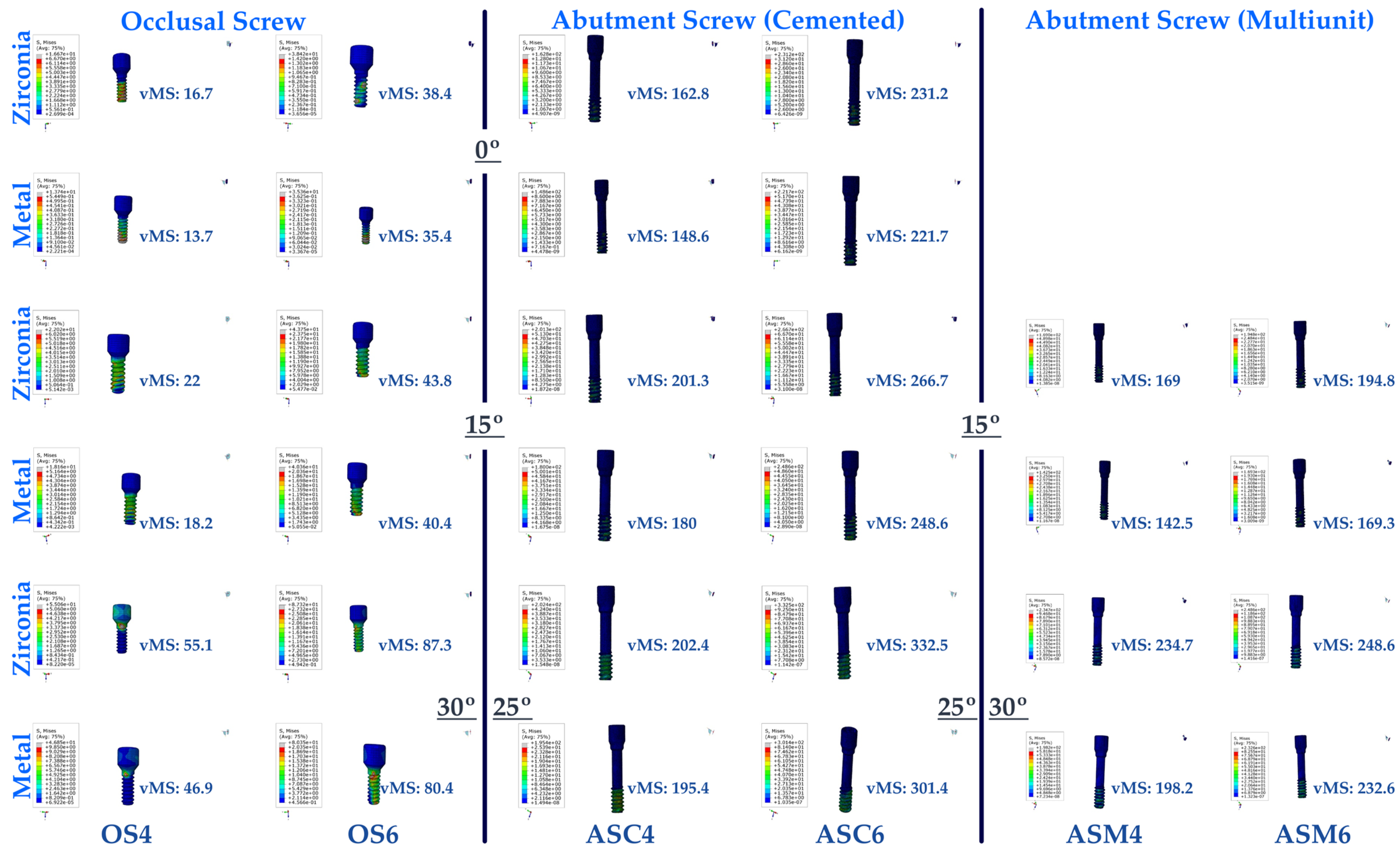
When the vMS on the abutment/multi-unit screw were analyzed, the highest vMS was found in Mu30Z. The lowest vMS was also seen in multi-unit restorations. Among these restorations, PFBM restorations with a 15-degree angle were found to have the lowest vMS. In direct proportion to the increase in angulation, there is an increase in the vMS values of the abutment/multi-unit screw in both PFBZ and PFBM restorations. The vMS values of the abutment/multi-unit screw of PFBM restorations were lower than PFBZ restorations in all angle groups. In the 15-degree-angle groups, screw-retained restorations showed lower vMS, regardless of the framework. With increasing angulation, multi-unit restorations were found to have higher vMS than resin-cemented restorations.
When the vMS on the abutment/multi-unit screw in the molar region was examined, the highest vMS was seen for C25Z. In both regions (premolar and molar), the lowest vMS was found in C15M. In direct proportion to the increase in angulation, an increase in the vMS to the abutment/multi-unit screw was observed in both PFBZ and PFBM restorations. The vMS to the abutment/multi-unit screw of PFBM restorations were lower than those of PFBZ restorations in all angle groups. Multi-unit restorations showed lower vMS regardless of the framework material, while resin-cemented restorations obtained higher vMS values in each group.
The resultant vMS of the abutment/multi-unit screw in the restoration to the applied stress was lower in each angulation, restoration type, and framework material group in the premolar region.

3.1.6. Stress Values on the Occlusal Screw

The highest vMS on the occlusal screws of multi-unit restorations in the premolar region was observed in the occlusal screw of Mu30Z, while the lowest vMS was observed in the occlusal screw of Mu0M. In multi-unit restorations, an increase in occlusal screws in both frameworks was observed in direct proportion to the increase in angle. The vMS values of the occlusal screws in PFBM restorations were lower than the occlusal screw vMS values in PFBZ restorations.
In the molar area, results matching the premolar area were obtained. The lowest occlusal screw vMS was seen in Mu0M, while the highest vMS was found in Mu30Z. Similarly, in this region, the resultant vMS on the occlusal screw increased with increasing angles. The occlusal screw vMS values of PFBZ restorations were higher than those of PFBM restorations.
The result of the applied stress on the occlusal screws was found to be lower in the premolar region than in the molar region in all framework and angulation groups (Figure 8).

3.1.7. Stress Values on the Resin Cement

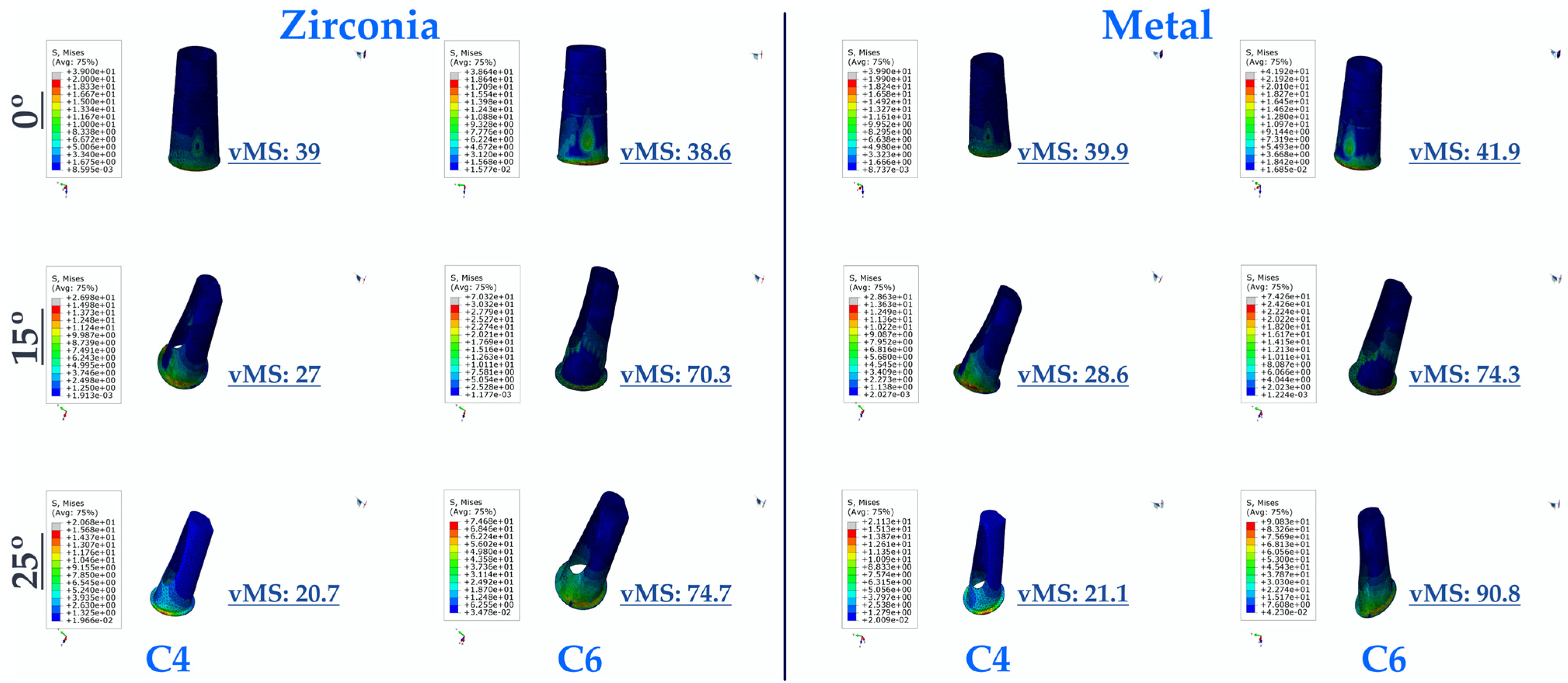
When the vMS on the cement in resin-cemented restorations were analyzed, the highest vMS in the premolar region was observed in C0M. In addition, the lowest vMS was found in C25Z. An inversely proportional decrease in the vMS on the resin cement was observed in both PFBM and PFBZ restorations with increasing angles. The vMS values in the resin cements of PFBM restorations were higher than those of PFBZ restorations in each angle group.
In the resin cement vMS of restorations in the molar region, the lowest data were obtained in C0Z. The highest vMS was found in C25M. Both frameworks of restorations show an increase in resin cement vMS with increasing angles. It was determined that the resin cement vMS values of PFBM restorations were higher than PFBZ restorations.
The resultant vMS of the resin cement in the restoration to the applied stress was generally lower in the premolar groups. Differently, in C0Z, slightly higher resin cement vMS values were obtained in the premolar region than in the molar region (Figure 9).

3.2. Fatigue Performance

3.2.1. Fatigue Performance of Implant

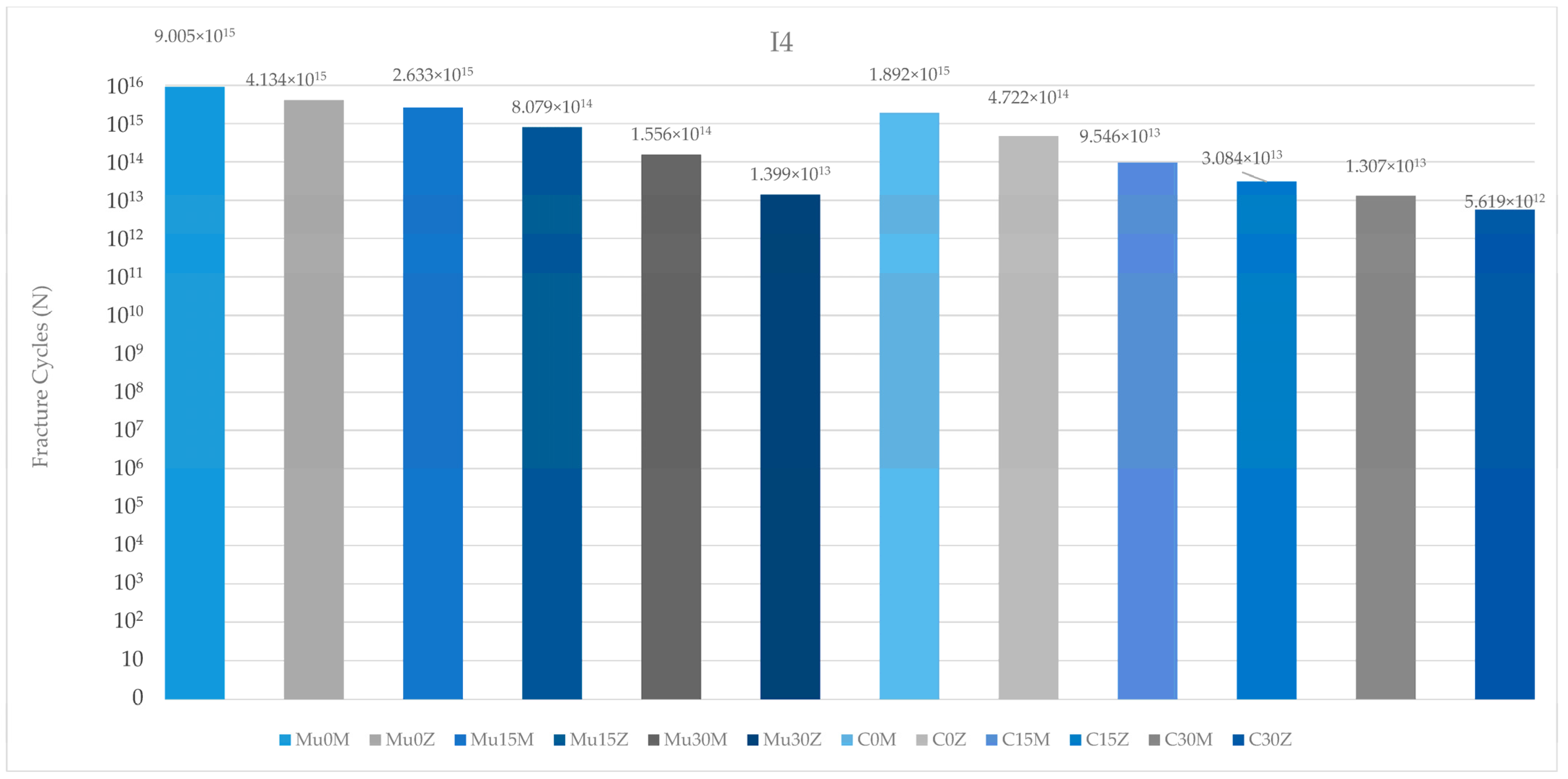
According to the data obtained as a result of this study, the highest implant fatigue performance in the premolar region was observed in Mu0M. On the other hand, the poorest implant fatigue performance was recorded in C25Z. Regardless of the type of abutment (multi-unit or resin cemented), fatigue performance decreased inversely with increasing angles. Again, in both restoration types, implants with PFBZ showed lower values than implants with PFBM. Multi-unit restorations were more successful than resin-cemented restorations (Figure 10).
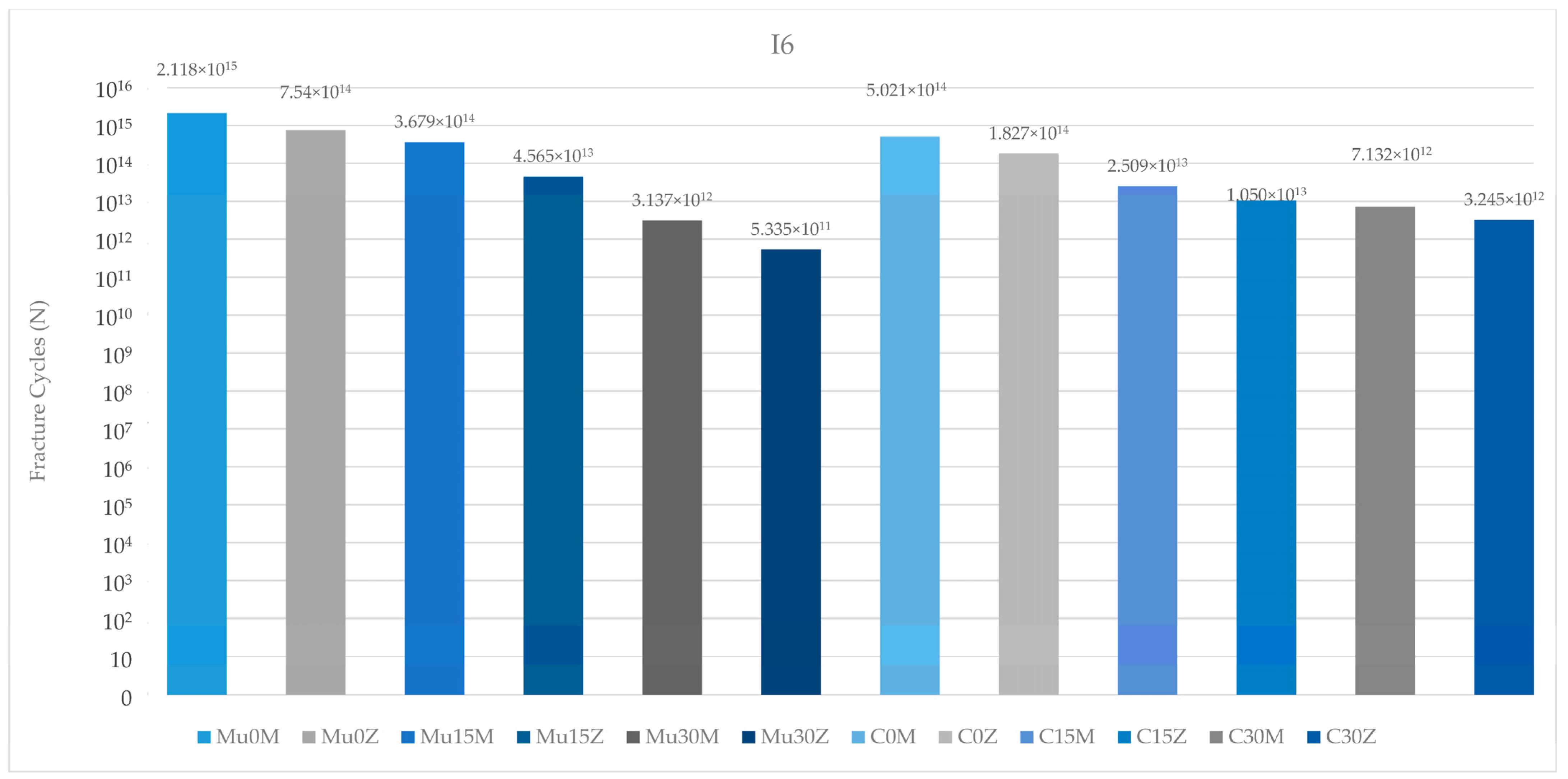
Regarding the fatigue performance of the implants in the molar region, the highest value was seen in the metal-framework restoration with no angle, while the lowest value was found in Mu30Z. As in the premolar region, an increase in the angle—independent of the restoration and framework material—led to a decrease in fatigue performance. In both frameworks, the implant in the multi-unit restoration generally achieved higher values than the implant in the resin-cemented restoration. In addition, the implant in C25M performed better than the implant in Mu30M. PFBZ restorations showed lower fatigue performance than the implants of PFBM restorations in each group (Figure 11).
Considering the fatigue performance of the implants in both regions, the results in the premolar region were more successful than the results in the molar region.

3.2.2. Fatigue Performance of Abutment

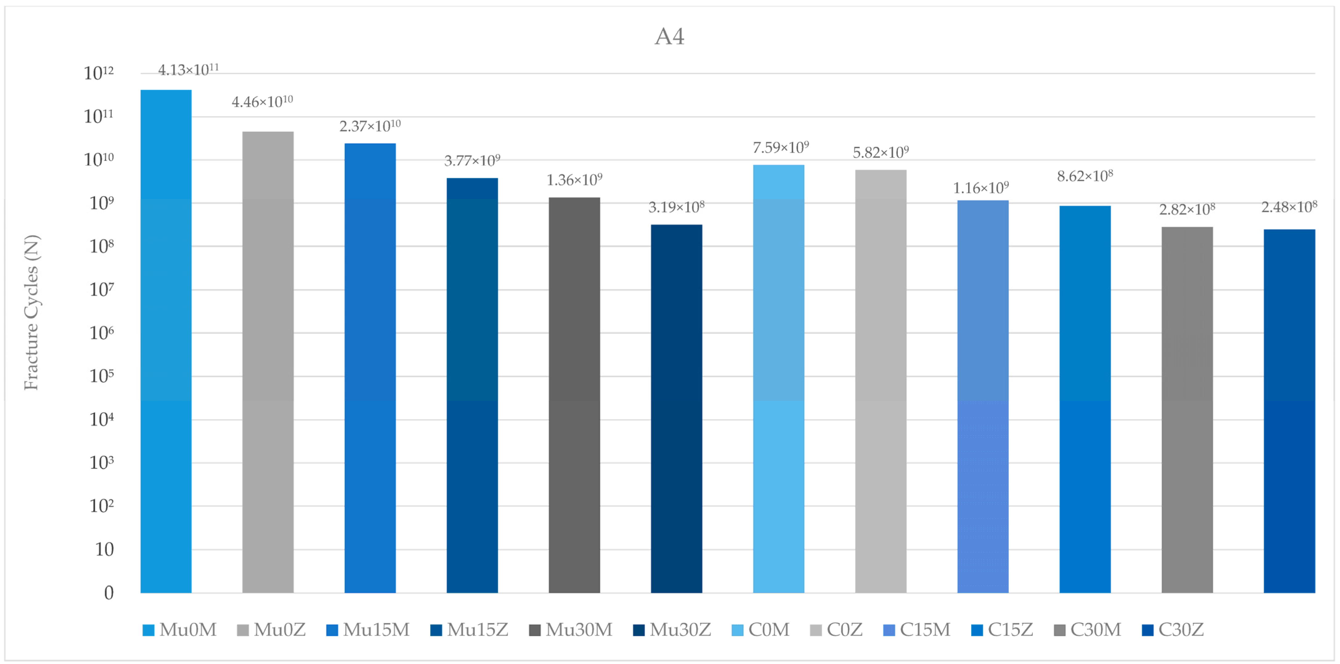
When the fatigue performance of the abutments in the premolar region was analyzed, the highest value was found in Mu0M, while the lowest value was found in C25Z. In both restoration types (multi-unit and resin cemented), the fatigue performance of the abutments in the PFBM group was higher than the abutments in the PFBZ group. Increasing the angles caused a decrease in the fatigue performance of the abutments in each group. The abutments in the multi-unit restoration achieved higher performance results in each framework group than the abutments in the resin-cemented restoration (Figure 12).
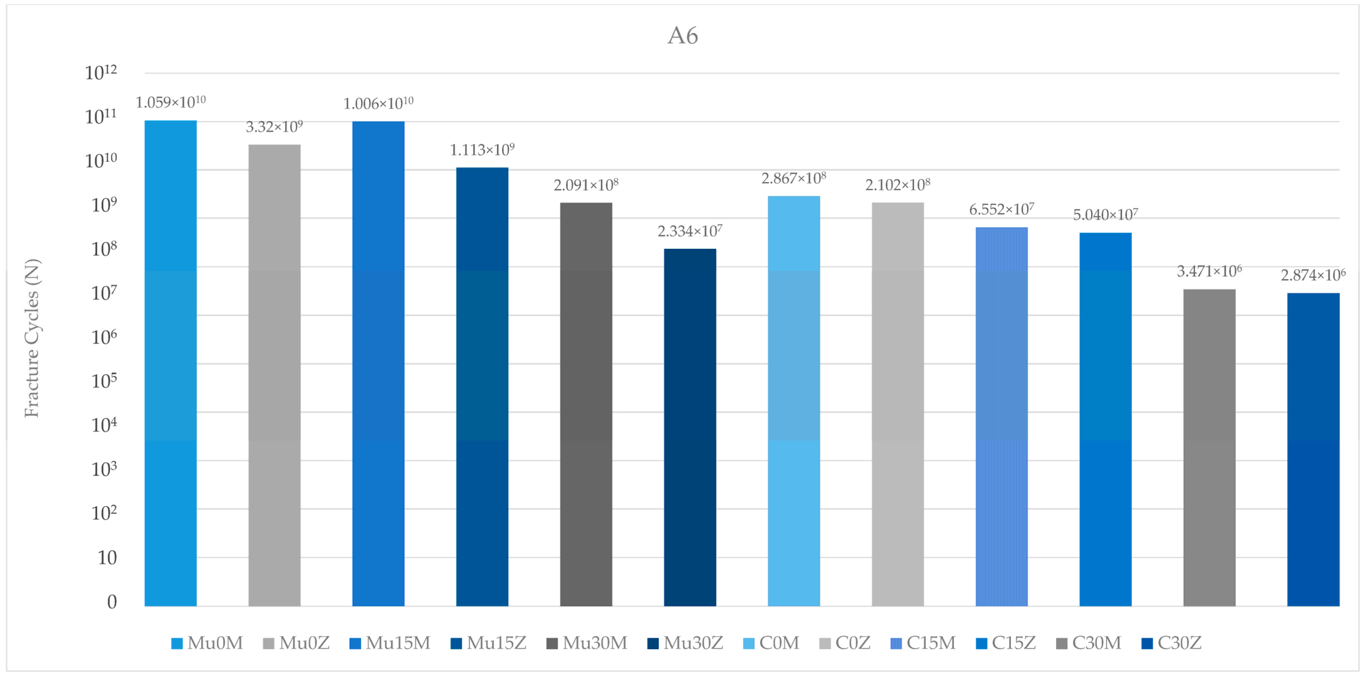
The results of the abutments in the molar region generally match the results of the abutments in the premolar region. Again, the highest value was seen in Mu0M, while the lowest value was found in C25Z. In both types of abutments (multi-unit and resin cemented), there was a decrease in values inversely proportional to the increase in angle. Contrary to this result, the abutment in Mu15M showed higher fatigue performance than the abutment in Mu0Z. Similar to the abutments in the premolar region, the abutments in this region also achieved better fatigue performance in both frameworks in multi-unit restorations. On the other hand, the fatigue performance of abutments in PFBZ restorations was lower in each group (Figure 13).
When the fatigue performance of the abutments was analyzed, the results in the premolar region were found to be higher than in the molar region.

3.2.3. Fatigue Performance of Abutment Screw

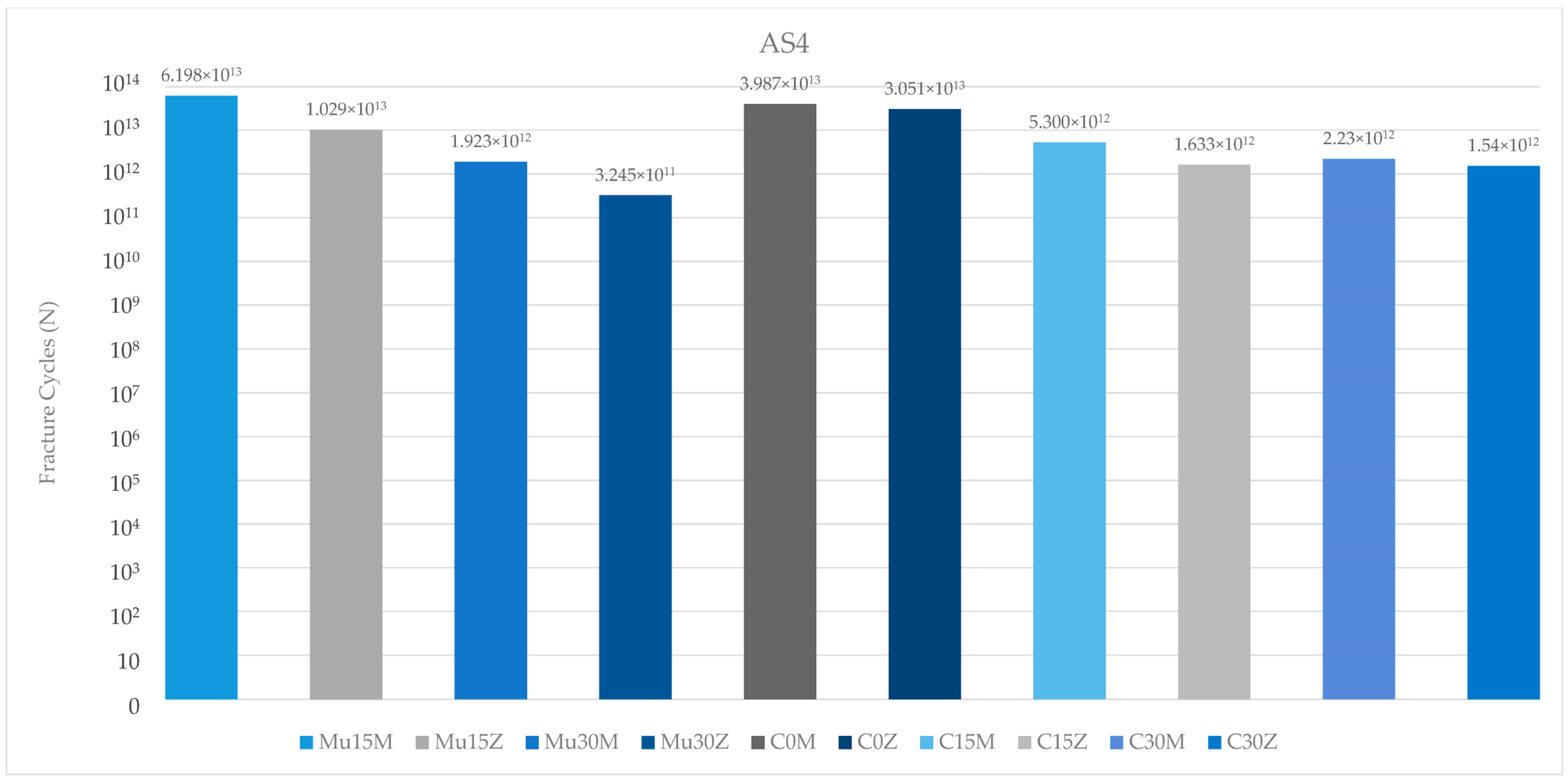
Regarding the fatigue performance of the abutment screws used in this study in the premolar region, the highest value was seen in Mu15M. The lowest value was found in the abutment screw of Mu30Z. Increasing the angle caused a decrease in the fatigue performance of the abutment screws. In addition, compared to the abutment screws of multi-unit and resin-cemented restorations with the same angle (15 degrees), multi-unit restorations were found to be higher in both frameworks. In both types of abutments (multi-unit and resin cemented), abutment screws in PFBZ were found to have lower fatigue performance (Figure 14).
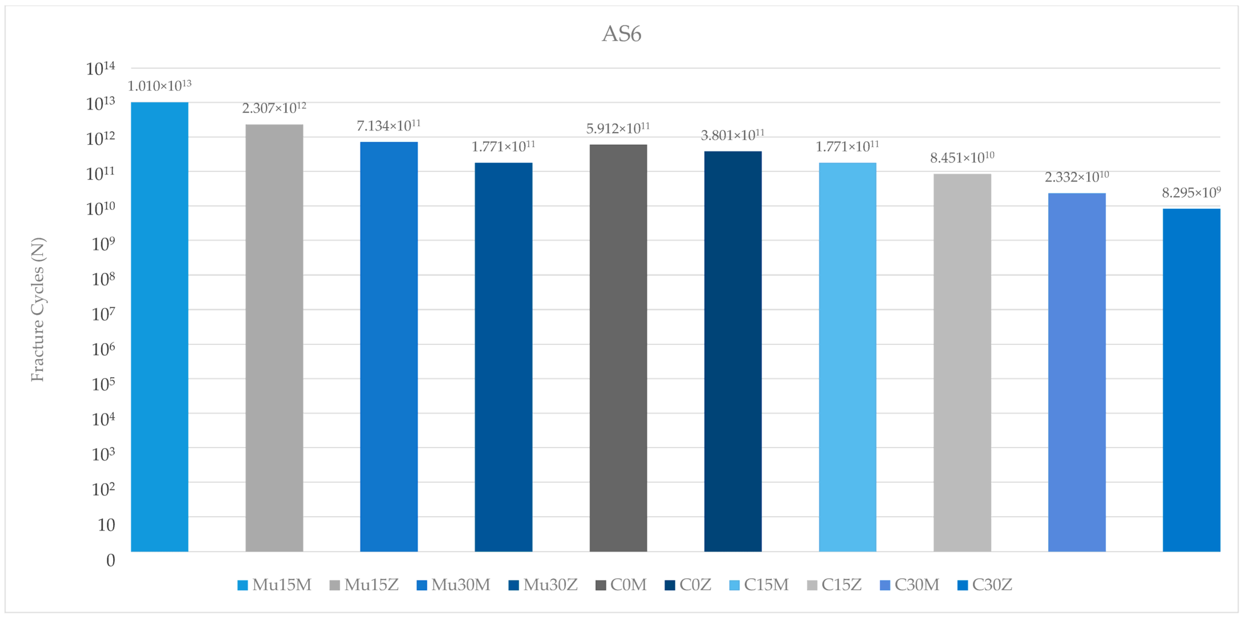
Among the fatigue performance of the abutment screws in the molar region, the highest value was found in Mu15M. The lowest abutment screw fatigue performance was found in C25Z. In all groupings, fatigue performance of the abutment screw decreased inversely with increasing angles. In multi-unit restorations, abutment screws exhibited higher fatigue performance than the resin-cemented groups. In addition, the abutment screws of PFBZ restorations always showed lower values than the PFBM groups (Figure 15).
Regarding the fatigue performance of the abutment screws, higher values were found in the premolar region than in the molar region, independently of the group.

3.2.4. Fatigue Performance of Occlusal Screw

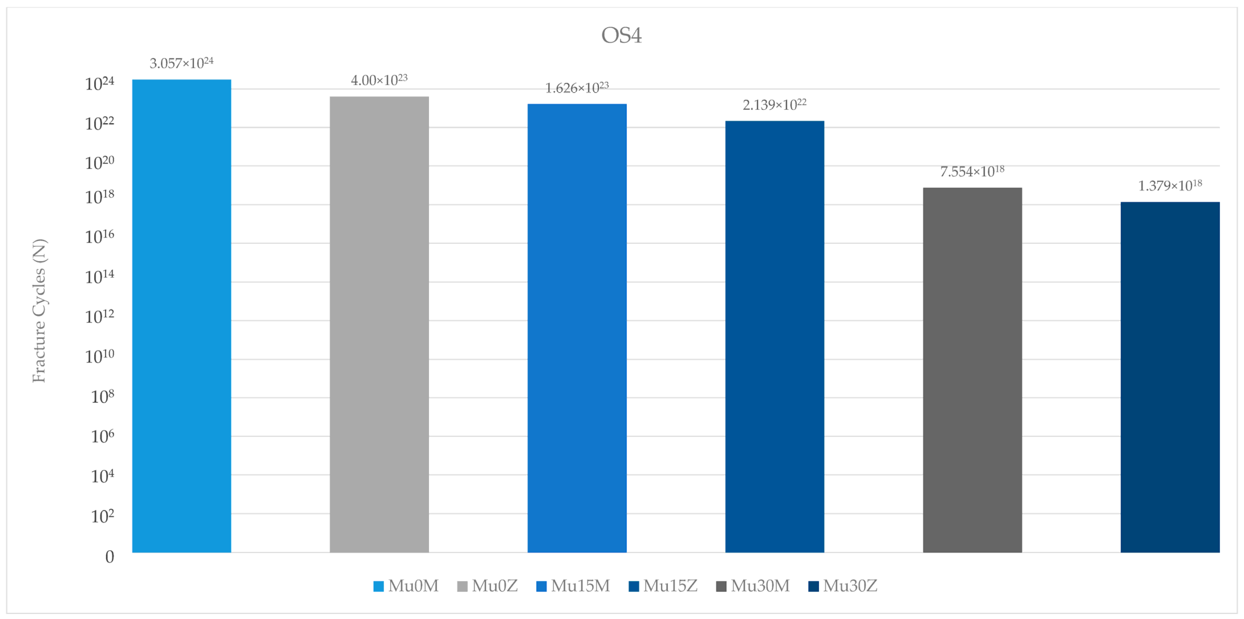
When the fatigue performance values of the occlusal screws in the premolar region were analyzed, the highest value was found in Mu0M. The lowest value was found in Mu30Z. An inversely proportional decrease in occlusal screw fatigue performance was observed with increasing angles, regardless of the framework. The occlusal screw in the PFBZ group showed a lower fatigue value than the PFBM restoration (Figure 16).
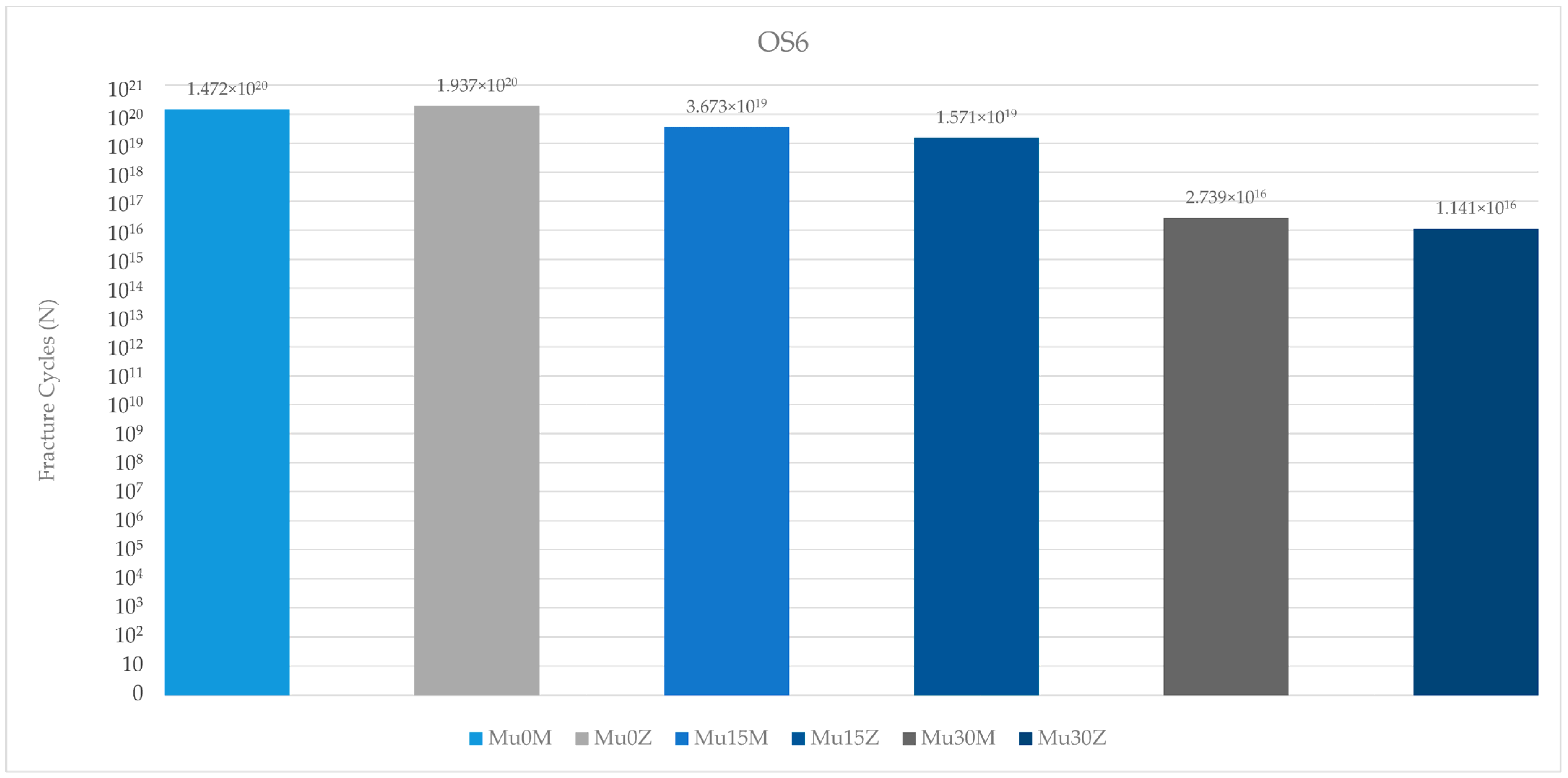
When the occlusal screw fatigue performance in the molar region was examined, the most successful value was found in Mu0Z. The poorest fatigue value was found in the occlusal screw of Mu30Z. In the occlusal screw of both types of framework restorations; increasing the angle caused a decrease in fatigue performance. Only in the group without an angle, the performance of the occlusal screw in the PFBZ obtained a higher value (Figure 17).
When the occlusal screw fatigue performance in both regions was analyzed, the values in the premolar region were more successful in both framework groups.

4. Discussion

This study evaluated the effect of the angle and type of abutments and the composition of the restoration framework on the stress distribution and fatigue performance of dental implant components. The null hypothesis was rejected. The composition of the crown framework material appears to influence the stress distribution and fatigue performance of the abutment–implant complex. In addition, high implant angulation also influenced stress distribution and fatigue performance.
The annual chewing cycle of an individual is recognized as 1,130,000 [55,56]. The results of the study were evaluated accordingly. Studies investigating the fatigue performance of dental restorations in molar and premolar regions are essential for understanding the durability and longevity of these treatments. Lovera-Prado et al. [57], found that dental implant fatigue limits differ across tooth regions, with premolars falling between incisors and molars in terms of values. Other studies have shown that the occlusal forces in the molar region can range from 250 to 400 N, while in the premolar region, they can vary from 140 to 170 N [58]. Consistent with the findings of these studies, in this study, lower fatigue performance values were obtained for implant components in the molar region than in the premolar region. As a result, it can be said that this part of this study is in line with the literature. The fatigue performance of abutments is also a critical aspect in implant dentistry. Consistent with studies reporting that fatigue failure will occur at the weakest point of the implant, the earliest deformation in the study was seen on the abutment in the molar region [59,60]. In addition, the highest fatigue strength was observed in the occlusal screw in the premolar region. The fatigue resistance of occlusal screws is influenced by various factors such as design, material, and loading conditions [61]. Additionally, the influence of the vertical misfit on screw fatigue behavior has been investigated, highlighting the importance of proper fit to prevent fatigue failure [62]. Proper insertion and the torquing of screws have been studied to assess their effect on screw loosening and fatigue resistance [63]. Additionally, the diameter of the occlusal access hole in screw-retained prostheses can affect the distribution of occlusal forces and potentially impact fatigue performance [64]. In conclusion, although it is unlikely to be feasible in real life due to physician or material manufacturing errors, as demonstrated in this study, the flawless application of occlusal screws is important for longevity and durability. Again, it is seen that these results are similar to the literature. Moreover, as expected, a decrease in fatigue strength was observed in each component as the angle increased. The lower stress observed at lower angles (0–15 degrees) suggests that there is a potential to reduce implant failure rates in clinical settings, highlighting the need for more precise angle assessments during surgical procedures. Multiple studies indicate a correlation between angle and fatigue properties [65,66,67,68]. Also, another study that underlines the importance of geometric parameters, such as angles, in influencing the fatigue properties of mechanical components, supports the results of the study [69]. This study suggests that the correct choice of framework material and restoration type will become more important as the angle increases. Multi-unit restorations have been a topic of interest in dental research, particularly in comparison to resin cement-retained restorations. Several studies have investigated the success rates and complications associated with these two types of restorations [70,71]. To determine the comparative fatigue performance of multi-unit versus resin-cemented restorations, it is crucial to consider studies that specifically address the fatigue behavior of these restorative techniques. In general, in this study, superior fatigue performance was obtained in the use of multi-unit restorations compared to resin-cemented restorations. Resin-cemented restorations obtained higher values only of the implant in the molar region and the abutment screw in the premolar region. The incompatibility of the angles between the two restoration types is thought to be the reason for this. As the angle increases, the choice of restoration type requires precision. Multi-unit restorations show superior success compared to resin-cemented restorations, even in cases with high angulations. This conclusion is also supported by the superior fatigue performance of the occlusal screw in the premolar region. As a result, it can be said that this part of this study is also in line with the literature. Based on this information, it can be concluded that multi-unit restorations should be preferred, especially in cases with large angulations. This could reduce stress levels in implants placed at increased angles. However, it should be noted that in this study, multi-unit restorations achieved superior fatigue performance compared to resin-cemented restorations, regardless of the angle. Moreover, the type of restoration framework can affect fatigue behavior. When PFBZ and PFBM materials were evaluated in this study, in general, PFBM restorations showed higher fatigue performance. Similar to this study, Jung et al. [72] discovered that the survival rate of metal–ceramic crowns was notably higher than that of all-ceramic crowns, indicating better longevity for metal–ceramic restorations. Similarly, Sailer et al. [73] observed a lower complication rate for PFBM fixed dental prostheses compared to PFBZ prostheses, further supporting the superior performance of metal–ceramic restorations in terms of durability. Furthermore, Hosseini et al. [74] pointed out a higher incidence of veneering fractures in zirconia crowns compared to metal–ceramic crowns, suggesting that metal–ceramic restorations may be more resistant to fatigue-related failures. This is consistent with the findings of Bajunaid et al. [75], who noted that ceramic materials, including zirconia, are susceptible to cohesive fractures and chipping, indicating potential weaknesses in zirconia restorations under fatigue conditions. As a result, it can be said that this part of this study is in line with the literature, too. Overall, the synthesis of these studies suggests that implant-supported metal–ceramic restorations may indeed offer better fatigue performance than implant-supported zirconia restorations. The evidence points toward the higher survival rates, lower complication rates, and a reduced incidence of veneering fractures associated with metal–ceramic restorations, highlighting their potential as a more durable option for long-term success in dental implant applications. Finite element analysis (FEA) was utilized in this study to explore the research hypothesis. FEA is a valuable computational tool commonly employed in the examination of various aspects related to dental restorations, biomaterials, restorative techniques, and prosthetic designs, particularly focusing on stress distribution under different loading conditions. This numerical simulation method enables a comprehensive investigation and quantification of the biomechanical responses demonstrated by complex dental structures. It is frequently utilized to analyze stress patterns in dental biomechanical studies. The modeling process assumed perfect joining of all components in different configurations and the material properties were considered isotropic and linear. Ignoring any potential errors that may occur during material production and preparation, the calculation of just 1000 cycles and use of finite element analysis may not fully capture the complex biomechanical interactions in vivo and are among the limitations of the present study. In future studies, it is recommended to verify the obtained findings with in vivo studies and to use higher cycle values to increase the reliability of the results.

5. Conclusions

This study aims to address an important research gap and provide a comprehensive perspective on the complex rehabilitation of implant-supported resin-cemented or screw-retained restorations where an angle is present, and to provide valuable information for clinical practice. Direct comparisons of fatigue performance between screw-retained and resin-cemented restorations are limited in the literature. This study eliminated this uncertainty. Thus, it contributes to the literature.
The results of this study are as follows:
  • In general, and especially in the case of implant restorations with an increased angle, the choice of multi-unit restorations will greatly increase the survival rate;
  • PFBZ does not offer an ideal treatment alternative for implant restorations. Implant restorations with PFBM are currently still a better alternative;
  • Occlusal screws are the most durable components when each stage is performed perfectly, in accordance with the procedure;
  • Considering the chewing force on the molar region, posterior implant planning should be performed precisely;
  • The placement of implants with a straight angle should be considered among the basic steps for the success of prosthetic treatments and surgical procedures should be carried out with sensitivity in this regard.

Author Contributions

Conceptualization, M.E. and M.G.D.; methodology, M.G.D., R.M. and M.G.C.; software, R.M. and M.G.C.; validation, M.E., M.G.D., R.M. and N.G.; formal analysis, R.M. and M.G.C.; investigation, M.E. and M.G.D.; resources, M.E.; data curation, M.E. and R.M.; writing—original draft preparation, M.E.; writing—review and editing, M.E., M.G.D., R.M. and N.G.; visualization, M.E., M.G.D. and R.M.; supervision, M.E., M.G.D., R.M. and N.G.; project administration, M.E., M.G.D. and R.M.; funding acquisition, M.E. All authors have read and agreed to the published version of the manuscript.

Funding

This research received no external funding.

Institutional Review Board Statement

Not applicable.

Informed Consent Statement

Not applicable.

Data Availability Statement

The raw data supporting the conclusions of this article will be made available by the authors upon request.

Acknowledgments

All the authors of this study thank to Bil Implant for their support in terms of the STL data of implant components.

Conflicts of Interest

The authors declare no conflicts of interest.

References

  1. Mosharraf, R.; Abbasi, M.; Givehchian, P. The Effect of Abutment Angulation and Crown Material Compositions on Stress Distribution in 3-Unit Fixed Implant-Supported Prostheses: A Finite Element Analysis. Int. J. Dent. 2022, 2022, 4451810. [Google Scholar] [CrossRef]
  2. de Souza Pereira, P.H.; Amaral, M.; Baroudi, K.; Vitti, R.P.; Nassani, M.Z.; Silva-Concílio, L.R. Effect of Implant Platform Connection and Abutment Material on Removal Torque and Implant Hexagon Plastic Deformation. Eur. J. Dent. 2019, 13, 349–353. [Google Scholar] [CrossRef]
  3. Pesce, P.; Fabbro, M.D.; Menini, M.; Giovanni, E.D.; Annunziata, M.; Khijmatgar, S.; Canullo, L. Effects of Abutment Materials on Peri-Implant Soft Tissue Health and Stability: A Network Meta-Analysis. J. Prosthodont. Res. 2023, 67, 506–517. [Google Scholar] [CrossRef] [PubMed]
  4. Yao, K.-T.; Chang, T.-Y.; Huang, G.-J.; Fang, H.-W.; Wang, D.-H.; Hsu, M.-L. Survival of Four Conical Implant Abutment Connections After Removal of the Abutment Screw and Simulated Cyclic Loading: An In Vitro Comparative Study. J. Oral Implantol. 2023, 49, 393–400. [Google Scholar] [CrossRef]
  5. Tao, B.; Feng, Y.; Fan, X.; Lan, K.; Zhuang, M.; Wang, S.; Wang, F.; Chen, X.; Wu, Y. The Accuracy of a Novel Image-guided Hybrid Robotic System for Dental Implant Placement: An in Vitro Study. Int. J. Med. Robot. Comput. Assist. Surg. 2022, 19, e2452. [Google Scholar] [CrossRef] [PubMed]
  6. Badalia, I.; Kumar, M.; Bansal, A.; Mehra, S.K.; Batra, R. Evaluation of Stress Patterns in Bone Around Implants for Different Abutment Angulations under Axial and Oblique Loading in Anterior Maxillary Region—A Finite Element Analysis. Dent. J. Adv. Stud. 2020, 8, 60–64. [Google Scholar] [CrossRef]
  7. Hassan, S.S.M.; Emarah, A. All on 4 Versus All on 6 Implant Concepts for Rehabilitation of Edentulous Maxilla. Short Term Randomized Clinical and Radiographic Study. Egypt. Dent. J. 2020, 66, 659–670. [Google Scholar] [CrossRef]
  8. Nag, P.V.R.; Ramanathan, M.; Puppala, S.; Daniel, S.; Vasundhara, K.A. Rehabilitation of Atrophic Posterior Partial Edentulous Maxilla with TTPHIL ALL TILT® Technique: 3 Year Follow-Up Case Report. Braz. Dent. Sci. 2022, 25, e3315. [Google Scholar] [CrossRef]
  9. Wu, A.Y.; Hsu, J.-T.; Fuh, L.; Huang, H. Effects of Positions and Angulations of Titanium Dental Implants in Biomechanical Performances in the All-on-Four Treatment: 3D Numerical and Strain Gauge Methods. Metals 2020, 10, 280. [Google Scholar] [CrossRef]
  10. Khairallah, A.; Hamed, M. Biological and Prosthetic Complications of Cantilevered and Non-Cantilevered Fixed Hybrid Metal Acrylic Prostheses Used for Vertical and Inclined Implants in Atrophied Mandible. A Randomized Clinical Trial. Egypt. Dent. J. 2021, 67, 717–728. [Google Scholar] [CrossRef]
  11. Scotton, R.; Claudino, D.D.; Savaris, L.B.; Mendes, F.M.F.; de Oliveira Stroparo, J.L.; Storrer, C.L.M.; Rezende, C.E.E.; Macedo, R.M.; Gabardo, M.C.L.; Zielak, J.C. Stress Distribution around Short Implants with Different Frictional Joint Designs: A Photoelastic Colorimetric Analysis/Distribuição De Tensão Em Torno De Implantes Curtos Com Diferentes Designs De Fricção: Uma Análise Colorimétrica. Brazilian J. Dev. 2021, 7, 106244–106255. [Google Scholar] [CrossRef]
  12. Rostom, D.A.; Ragheb, N. Retention and Wear Characteristic Assessment of OT Equator with Smart Box Attachment Versus Ball Attachment for Mandibular Two Implant Assisted Over Denture. In-Vitro Study. Egypt. Dent. J. 2021, 67, 3525–3532. [Google Scholar] [CrossRef]
  13. Kitagawa, T.; Tanimoto, Y.; Murakami, H.; Igeta, S.; Tamaki, H.; Komiyama, O.; Kato, T. Evaluating the Dynamic Behavior of Taper Joint Implants under Different Loading Conditions:A Transient Dynamic Finite Element Analysis. Int. J. Oral-Med. Sci. 2013, 12, 105–111. [Google Scholar] [CrossRef]
  14. Hamza, G.E.; El-Zawahry, M.M.; ElGbary, H.S.; El-Anwar, M.I. Angulated Dental Implant Versus Vertical One Finite Element Study. J. Int. Soc. Sci. Eng. 2021, 3, 18–24. [Google Scholar] [CrossRef]
  15. Özdoğan, M.; Gokce, H.; Şahin, İ. Effect of Straight and Angled Abutments on the Strain on a Zirconia Crown and Implant in the Mandibular Second Molar Region: A Fea-Based Study. Mater. Tehnol. 2020, 54, 251–257. [Google Scholar] [CrossRef]
  16. Anitua, E.; Fernández-de-Retana, S.; Alkhraisat, M.H. Survival and Marginal Bone Loss of Dental Implants Supporting Cad-Cam Angled Channel Restorations: A Split-Mouth Retrospective Study. Eur. J. Dent. 2020, 14, 194–199. [Google Scholar] [CrossRef]
  17. Frantz, K.; Funkenbusch, P.; Feng, C.; Tsigarida, A.; Chochlidakis, K.; Lo Russo, L.; Ercoli, C. Effect of Implant Angulation and Patrice on the Retention of Overdenture Attachment Systems: An in Vitro Study. J. Prosthodont. 2023, 33, 452–459. [Google Scholar] [CrossRef]
  18. Wadia, R. Abutment Material and Peri-Implant Soft Tissue. Br. Dent. J. 2020, 228, 82. [Google Scholar] [CrossRef]
  19. Laleman, I.; Lambert, F. Implant Connection and Abutment Selection as a Predisposing and/or Precipitating Factor for Peri-Implant Diseases: A Review. Clin. Implant Dent. Relat. Res. 2023, 25, 723–733. [Google Scholar] [CrossRef]
  20. Laleman, I.; Lambert, F.; Gahlert, M.; Bacevic, M.; Woelfler, H.; Roehling, S. The Effect of Different Abutment Materials on Peri-Implant Tissues—A Systematic Review and Meta-Analysis. Clin. Oral Implants Res. 2023, 34 (Suppl. S26), 125–142. [Google Scholar] [CrossRef]
  21. Dayan, S.C.; Geckili, O. The Influence of Framework Material on Stress Distribution in Maxillary Complete-Arch Fixed Prostheses Supported by Four Dental Implants: A Three-Dimensional Finite Element Analysis. Comput. Methods Biomech. Biomed. Engin. 2021, 24, 1606–1617. [Google Scholar] [CrossRef]
  22. Rismanchian, M.; Davoudi, A.; Nosouhian, S.; Tabesh, M.; Rismanchian, M. Internal and Marginal Fit Accuracy of Pre-Sintered CAD/CAM Implant-Supported Frameworks before and after Porcelain Layering. Int. J. Oral Maxillofac. Implants 2022, 37, 601–607. [Google Scholar] [CrossRef] [PubMed]
  23. Aboelfadl, A.; Taha, M.M. Effect of Implant Abutment Venting on Peri-Implant Soft Tissue Response. A Randomized Clinical Trial. Egypt. Dent. J. 2018, 64, 1813–1824. [Google Scholar] [CrossRef]
  24. Alsubaiy, E.F. Abutment Screw Loosening in Implants: A Literature Review. J. Fam. Med. Prim. Care 2020, 9, 5490–5494. [Google Scholar] [CrossRef]
  25. Londhe, S.M.; Gowda, E.M.; Mandlik, V.B.; Shashidhar, M.P. Factors Associated with Abutment Screw Loosening in Single Implant Supported Crowns: A Cross-Sectional Study. Med. J. Armed Forces India 2020, 76, 37–40. [Google Scholar] [CrossRef]
  26. Amini, P. Evaluation of the Effect of Surface Roughness and Modification of Implant Abutment Axial Wall on the Retention of Zirconium Oxide Copings before and after Thermocycling. J. Clin. Exp. Dent. 2024, 16, e399–e405. [Google Scholar] [CrossRef]
  27. Kim, H.J.; Karasan, D.; Park, K.; Kwon, H.-B.; Han, J.; Lee, J. Abutment Margin Levels and Residual Cement Occurrence in Cement-retained Implant Restorations: An Observational Study. Clin. Oral Implants Res. 2022, 34, 33–41. [Google Scholar] [CrossRef] [PubMed]
  28. Gönder, A.; Polat, S.; Kılıçarslan, M.A.; Ocak, M.; Tamam, E. How Can Excess Residual Cement Be Reduced in Implant-Supported Restorations?: An in Vitro Study. Clin. Implant Dent. Relat. Res. 2023, 25, 807–814. [Google Scholar] [CrossRef]
  29. Çeken, A. Effect of Abutment Types and Resin Cements on the Esthetics of Implant-Supported Restorations. J. Adv. Prosthodont. 2023, 15, 114. [Google Scholar] [CrossRef]
  30. Salama, A.; Radwan, M.M.; Bushra, S. Influence of Thermo-Mechanical Aging on Straight Versus Angled Multi-Unit Abutments Screw Joint Stability. Egypt. Dent. J. 2023, 69, 487–495. [Google Scholar] [CrossRef]
  31. Güven, M.E. Effect of Dynamic Cycles and Abutment Angle on the Screw Stability of Standard and Narrow Implants: An in Vitro Study. Med. Sci. Discov. 2023, 10, 911–917. [Google Scholar] [CrossRef]
  32. Müller, L.; Rauch, A.; Reissmann, D.R.; Schierz, O. Impact of Cement Type and Abutment Height on Pull-Off Force of Zirconia Reinforced Lithium Silicate Crowns on Titanium Implant Stock Abutments: An in Vitro Study. BMC Oral Health 2021, 21, 592. [Google Scholar] [CrossRef] [PubMed]
  33. Hamed, M.T.; Mously, H.A.; Alamoudi, S.K.; Hashem, A.B.H.; Naguib, G.H. A Systematic Review of Screw Versus Cement-Retained Fixed Implant Supported Reconstructions. Clin. Cosmet. Investig. Dent. 2020, 12, 9–16. [Google Scholar] [CrossRef]
  34. Kanneganti, K.C.; Vinnakota, D.N.; Pottem, S.R.; Pulagam, M. Comparative Effect of Implant-Abutment Connections, Abutment Angulations, and Screw Lengths on Preloaded Abutment Screw Using Three-Dimensional Finite Element Analysis: An in Vitro Study. J. Indian Prosthodont. Soc. 2018, 18, 161. [Google Scholar] [CrossRef]
  35. Kan, J.Y.K.; Rungcharassaeng, K.; Kamolroongwarakul, P.; Lin, G.; Matsuda, H.; Yin, S.; Wang, H.; Tarnow, D.P.; Lozada, J. Frequency of Screw-retained Angulated Screw Channel Single Crown Following Immediate Implant Placement and Provisionalization in the Esthetic Zone: A Cone Beam Computed Tomography Study. Clin. Implant Dent. Relat. Res. 2023, 25, 789–794. [Google Scholar] [CrossRef] [PubMed]
  36. Emam, M.; Arafa, M.A. Stress Distribution and Fracture Resistance of Green Reprocessed Polyetheretherketone (PEEK) Single Implant Crown Restorations Compared to Unreprocessed PEEK and Zirconia: An in-Vitro Study. BMC Oral Health 2023, 23, 275. [Google Scholar] [CrossRef] [PubMed]
  37. Fayyad, A. Comparison Between Two Different Unilateral Mandibular Partial Denture Designs Retained by Extra-Coronal Attachment. An In-Vitro Study. Egypt. Dent. J. 2022, 68, 2479–2485. [Google Scholar] [CrossRef]
  38. Barragán-Paredes, M.A.; Mosquera-Victoria, I.; Viveros-Rebolledo, C.A.; Rodríguez-Paz, M.L.; Muñoz-Vélez, M.F.; Llano, C.H.V. Comparison of the Mechanical Properties of Temporary Abutments Made of Polyetheretherketone and Photopolymeric Resin. Open Dent. J. 2021, 15, 512–519. [Google Scholar] [CrossRef]
  39. Yilmaz, B.; Alsaery, A.; Altintas, S.H.; Schimmel, M. Comparison of Strains for New Generation CAD-CAM Implant-supported Crowns under Loading. Clin. Implant Dent. Relat. Res. 2020, 22, 397–402. [Google Scholar] [CrossRef]
  40. Takata, H.; Komine, F.; Honda, J.; Blatz, M.B.; Matsumura, H. An in Vitro Evaluation of Fracture Load of Implant-supported Zirconia-based Prostheses Fabricated with Different Veneer Materials. Clin. Oral Implants Res. 2018, 29, 396–403. [Google Scholar] [CrossRef]
  41. Zhang, X.; Mao, J.; Zhou, Y.; Ji, F.; Chen, X. Mechanical Properties and Osteoblast Proliferation of Complex Porous Dental Implants Filled with Magnesium Alloy Based on 3D Printing. J. Biomater. Appl. 2020, 35, 1275–1283. [Google Scholar] [CrossRef] [PubMed]
  42. Poovarodom, P.; Rungsiyakull, C.; Suriyawanakul, J.; Li, Q.; Sasaki, K.; Yoda, N.; Rungsiyakull, P. Effect of Implant Placement Depth on Bone Remodeling on Implant-Supported Single Zirconia Abutment Crown: A 3D Finite Element Study. J. Prosthodont. Res. 2023, 67, 278–287. [Google Scholar] [CrossRef] [PubMed]
  43. Sevimay, M.; Üşümez, A.; Eskitaşçıoğlu, G. The Influence of Various Occlusal Materials on Stresses Transferred to Implant-supported Prostheses and Supporting Bone: A Three-dimensional Finite-element Study. J. Biomed. Mater. Res. Part B Appl. Biomater. 2005, 73, 140–147. [Google Scholar] [CrossRef] [PubMed]
  44. Bakitian, F.; Papia, E.; Larsson, C.; von Steyern, P.V. Evaluation of Stress Distribution in Tooth-Supported Fixed Dental Prostheses Made of Translucent Zirconia with Variations in Framework Designs: A Three-Dimensional Finite Element Analysis. J. Prosthodont. 2020, 29, 315–322. [Google Scholar] [CrossRef] [PubMed]
  45. Agustín-Panadero, R.; Román-Rodríguez, J.-L.; Ferreiroa, A.; Solá-Ruíz, M.F.; Fons-Font, A. Zirconia in Fixed Prosthesis. A Literature Review. J. Clin. Exp. Dent. 2014, 6, e66–e73. [Google Scholar] [CrossRef]
  46. Alqahtani, A.R.; Desai, S.R.; Patel, J.R.; Alqhtani, N.R.; Alqahtani, A.S.; Heboyan, A.; Fernandes, G.V.O.; Mustafa, M.; Karobari, M.I. Investigating the Impact of Diameters and Thread Designs on the Biomechanics of Short Implants Placed in D4 Bone: A 3D Finite Element Analysis. BMC Oral Health 2023, 23, 686. [Google Scholar] [CrossRef]
  47. Al-Kordy, N.M.T.A.; Al-Saadi, M.H. Finite Element Study of Stress Distribution with Tooth-Supported Mandibular Overdenture Retained by Ball Attachments or Resilient Telescopic Crowns. Eur. J. Dent. 2023, 17, 539–547. [Google Scholar] [CrossRef]
  48. Mozaffari, A.; Hashtbaran, D.; Moghadam, A.; Aalaei, S. Stress Distribution in Peri-Implant Bone in the Replacement of Molars with One or Two Implants: A Finite Element Analysis. J. Dent. 2023, 24, 132. [Google Scholar]
  49. Ersöz, M.B.T.; Mumcu, E. Biomechanical Investigation of Maxillary Implant-Supported Full-Arch Prostheses Produced with Different Framework Materials: A Finite Elements Study. J. Adv. Prosthodont. 2022, 14, 346. [Google Scholar] [CrossRef]
  50. Chen, S.; Hong, X.; Ye, Z.; Wu, M.; Chen, L.; Wu, L.; Wang, Y.; Chen, Y.; Wu, J.; Wang, J. The Effect of Root Canal Treatment and Post-Crown Restorations on Stress Distribution in Teeth with Periapical Periodontitis: A Finite Element Analysis. BMC Oral Health 2023, 23, 973. [Google Scholar] [CrossRef]
  51. Brown, M.W.; Miller, K.J. A Theory for Fatigue Failure under Multiaxial Stress-Strain Conditions. Proc. Inst. Mech. Eng. 1973, 187, 745–755. [Google Scholar] [CrossRef]
  52. Duan, Y.; Gonzalez, J.A.; Kulkarni, P.A.; Nagy, W.W.; Griggs, J.A. Fatigue Lifetime Prediction of a Reduced-Diameter Dental Implant System: Numerical and Experimental Study. Dent. Mater. 2018, 34, 1299–1309. [Google Scholar] [CrossRef]
  53. Young, C.S.; Durham, J.C. Industrial Applications of Titanium and Zirconium: Fourth Volume: A Symposium; ASTM International: West Conshohocken, PA, USA, 1986; Volume 4, ISBN 0803104847. [Google Scholar]
  54. Allum, S.R.; Tomlinson, R.A.; Joshi, R. The Impact of Loads on Standard Diameter, Small Diameter and Mini Implants: A Comparative Laboratory Study. Clin. Oral Implants Res. 2008, 19, 553–559. [Google Scholar] [CrossRef] [PubMed]
  55. Fuentes, R.; Arias, A.; Lezcano, M.F.; Saravia, D.; Kuramochi, G.; Navarro, P.; Días, F.J. A New Tridimensional Insight into Geometric and Kinematic Characteristics of Masticatory Cycles in Participants with Normal Occlusion. Biomed Res. Int. 2018, 2018, 2527463. [Google Scholar] [CrossRef] [PubMed]
  56. van Casteren, A.; Codd, J.R.; Kupczik, K.; Plasqui, G.; Sellers, W.I.; Henry, A.G. The Cost of Chewing: The Energetics and Evolutionary Significance of Mastication in Humans. Sci. Adv. 2024, 8, eabn8351. [Google Scholar] [CrossRef] [PubMed]
  57. Lovera-Prado, K.; Vanaclocha, V.; Atienza, C.M.; Vanaclocha, A.; Jordá-Gómez, P.; Saiz-Sapena, N.; Vanaclocha, L. Barbed Dental Ti6Al4V Alloy Screw: Design and Bench Testing. Materials 2023, 16, 2228. [Google Scholar] [CrossRef]
  58. Lee, W.-T.; Koak, J.; Lim, Y.; Kim, S.-K.; Kwon, H.-B.; Kim, M. Stress Shielding and Fatigue Limits of Poly-ether-ether-ketone Dental Implants. J. Biomed. Mater. Res. Part B Appl. Biomater. 2012, 100, 1044–1052. [Google Scholar] [CrossRef]
  59. López-Píriz, R.; Cabal, B.; Goyos-Ball, L.; Fernández, A.; Bartolomé, J.F.; Moya, J.S.; Torrecillas, R. Current State-of-the-art and Future Perspectives of the Three Main Modern Implant-dentistry Concerns: Aesthetic Requirements, Mechanical Properties, and Peri-implantitis Prevention. J. Biomed. Mater. Res. Part A 2019, 107, 1466–1475. [Google Scholar] [CrossRef]
  60. Lauritano, D.; Moreo, G.; Lucchese, A.; Viganoni, C.; Limongelli, L. The Impact of Implant–Abutment Connection on Clinical Outcomes and Microbial Colonization: A Narrative Review. Materials 2020, 13, 1131. [Google Scholar] [CrossRef]
  61. Cho, W.-R.; Huh, Y.; Park, C.-J.; Cho, L. Effect of Cyclic Loading and Retightening on Reverse Torque Value in External and Internal Implants. J. Adv. Prosthodont. 2015, 7, 288–293. [Google Scholar] [CrossRef]
  62. Abasolo, M.; Aguirrebeitia, J.; Vallejo, J.; Albizuri, J.; Coria, I. Influence of Vertical Misfit in Screw Fatigue Behavior in Dental Implants: A Three-Dimensional Finite Element Approach. Proc. Inst. Mech. Eng. Part H J. Eng. Med. 2018, 232, 1117–1128. [Google Scholar] [CrossRef] [PubMed]
  63. Arshad, M.; Shirani, G.; Refoua, S.; Yeganeh, M.R. Comparative Study of Abutment Screw Loosening with or without Adhesive Material. J. Adv. Prosthodont. 2017, 9, 99–103. [Google Scholar] [CrossRef]
  64. Choi, J.-W.; Lee, J.-J.; Bae, E.; Huh, J.-B. Implant-Supported Fixed Dental Prosthesis with a Microlocking Implant Prosthetic System: A Clinical Report. J. Prosthet. Dent. 2020, 123, 15–19. [Google Scholar] [CrossRef] [PubMed]
  65. de Campos, M.R.; Botelho, A.L.; dos Reis, A.C. Reasons for the Fatigue of Ball Attachments and Their O-Rings: A Systematic Review. Dent. Med. Probl. 2023, 60, 167–176. [Google Scholar] [CrossRef]
  66. Sun, F.; Lv, L.-T.; Cheng, W.; Zhang, J.-L.; Ba, D.; Song, G.; Lin, Z. Effect of Loading Angles and Implant Lengths on the Static and Fatigue Fractures of Dental Implants. Materials 2021, 14, 5542. [Google Scholar] [CrossRef] [PubMed]
  67. Atalay, P.; Öztaş, D.D. Fatigue Resistance and Fracture Strength of Narrow-diameter One-piece Zirconia Implants with Angled Abutments. J. Esthet. Restor. Dent. 2022, 34, 1060–1067. [Google Scholar] [CrossRef]
  68. Suzuki, H.; Hata, Y.; Watanabe, F. Implant Fracture under Dynamic Fatigue Loading: Influence of Embedded Angle and Depth of Implant. Odontology 2015, 104, 357–362. [Google Scholar] [CrossRef]
  69. Demet, S.M.; Ersoyoğlu, A.S. An Analysis of the Effect of Pressure Angle Change on Bending Fatigue Performance in Asymmetrical Spur Gears. Proc. Inst. Mech. Eng. Part L J. Mater. Des. Appl. 2021, 235, 2142–2150. [Google Scholar] [CrossRef]
  70. Kaweewongprasert, P.; Phasuk, K.; Levon, J.A.; Eckert, G.J.; Feitosa, S.; Valandro, L.F.; Bottino, M.C.; Morton, D. Fatigue Failure Load of Lithium Disilicate Restorations Cemented on a Chairside Titanium-Base. J. Prosthodont. 2018, 28, 973–981. [Google Scholar] [CrossRef]
  71. Pucci, C.R.; Mafetano, A.P.V.P.; Borges, A.L.S.; de Andrade, G.S.; Dal Piva, A.M.D.O.; Kleverlaan, C.J.; Tribst, J.P.M. Substrate Rigidity Effect on CAD/CAM Restorations at Different Thicknesses. Eur. J. Dent. 2022, 17, 1020–1028. [Google Scholar] [CrossRef]
  72. Jung, R.E.; Pjetursson, B.E.; Glauser, R.; Zembic, A.; Zwahlen, M.; Lang, N.P. A Systematic Review of the 5-year Survival and Complication Rates of Implant-supported Single Crowns. Clin. Oral Implants Res. 2007, 19, 119–130. [Google Scholar] [CrossRef] [PubMed]
  73. Sailer, I.; Strasding, M.; Valente, N.A.; Zwahlen, M.; Liu, S.; Pjetursson, B.E. A Systematic Review of the Survival and Complication Rates of Zirconia-Ceramic and Metal-Ceramic Multiple-Unit Fixed Dental Prostheses. Clin. Oral Implants Res. 2018, 29 (Suppl. S1), 184–198. [Google Scholar] [CrossRef] [PubMed]
  74. Hosseini, M.; Worsaae, N.; Gotfredsen, K. A 5-year Randomized Controlled Trial Comparing Zirconia-based Versus Metal-based Implant-supported Single-tooth Restorations in the Premolar Region. Clin. Oral Implants Res. 2022, 33, 792–803. [Google Scholar] [CrossRef] [PubMed]
  75. Bajunaid, S.O.; Alshiddi, I.F.; Alhomaidhi, L.; Almutairi, R.; Alolayan, S.; Habib, S.R. Comparison of the Fracture Resistance and Fracture Mode of Contemporary Restorative Materials to Overcome the Offset of Mandibular Implant-Supported, Cement-Retained Crowns. Materials 2021, 14, 4838. [Google Scholar] [CrossRef]
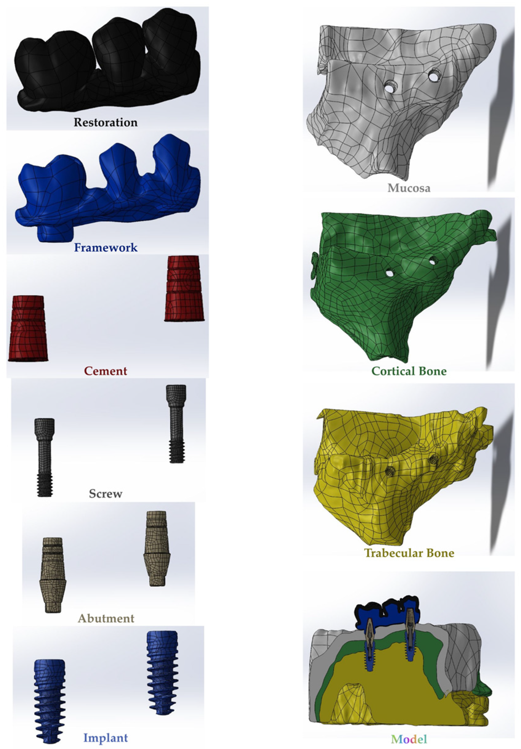
Figure 1. The final version of the obtained models.
Medicina 60 01463 g001
Figure 2. The key steps of the methodology.
Medicina 60 01463 g002
Figure 3. Screw preloading with the bone block fixed along the axes.
Medicina 60 01463 g003
Figure 4. Von Mises Stress on the implant. vMS: von Mises Stress; I4: implant in the premolar area; I6: implant in the molar area.
Medicina 60 01463 g004
Figure 5. Von Mises Stress on the abutment. vMS: von Mises Stress; A4: abutment in the premolar area; A6: abutment in the molar area.
Medicina 60 01463 g005
Figure 6. Von Mises Stress on the cortical bone. vMS: von Mises Stress.
Medicina 60 01463 g006
Figure 7. Von Mises Stress on the framework. vMS: von Mises Stress.
Medicina 60 01463 g007
Figure 8. Von Mises Stress on the screw. vMS: von Mises Stress; OS4: occlusal screw in the premolar area; OS6: occlusal screw in the molar area; ASC4: abutment screw of cemented restoration in the premolar area; ASC6: abutment screw of cemented restoration in the molar area; ASM4: abutment screw of multi-unit restoration in the premolar area; ASM6: abutment screw of multi-unit restoration in the molar area.
Medicina 60 01463 g008
Figure 9. Von Mises Stress on the resin cement. vMS: von Mises Stress; C4: resin cement in the premolar area; C6: resin cement in the molar area.
Medicina 60 01463 g009
Figure 10. Fracture cycles of implants in the premolar region. I4: implant in the premolar area; Mu0M: multi-unit 0-degree metal framework; Mu0Z: multi-unit 0-degree zirconia framework; Mu15M: multi-unit 15-degree metal framework; Mu15Z: multi-unit 15-degree zirconia framework; Mu30M: multi-unit 30-degree metal framework; Mu30Z: multi-unit 30-degree zirconia framework; C0M: cemented 0-degree metal framework; C0Z: cemented 0-degree zirconia framework; C15M: cemented 15-degree metal framework; C15Z: cemented 15-degree zirconia framework; C25M: cemented 25-degree metal framework; C25Z: cemented 25-degree zirconia framework.
Medicina 60 01463 g010
Figure 11. Fracture cycles of implants in the molar region. I6: implant in the molar area; Mu0M: multi-unit 0-degree metal framework; Mu0Z: multi-unit 0-degree zirconia framework; Mu15M: multi-unit 15-degree metal framework; Mu15Z: multi-unit 15-degree zirconia framework; Mu30M: multi-unit 30-degree metal framework; Mu30Z: multi-unit 30-degree zirconia framework; C0M: cemented 0-degree metal framework; C0Z: cemented 0-degree zirconia framework; C15M: cemented 15-degree metal framework; C15Z: cemented 15-degree zirconia framework; C25M: cemented 25-degree metal framework; C25Z: cemented 25-degree zirconia framework.
Medicina 60 01463 g011
Figure 12. Fracture cycles of abutments in the premolar region. A4: abutment in the premolar area; Mu0M: multi-unit 0-degree metal framework; Mu0Z: multi-unit 0-degree zirconia framework; Mu15M: multi-unit 15-degree metal framework; Mu15Z: multi-unit 15-degree zirconia framework; Mu30M: multi-unit 30-degree metal framework; Mu30Z: multi-unit 30-degree zirconia framework; C0M: cemented 0-degree metal framework; C0Z: cemented 0-degree zirconia framework; C15M: cemented 15-degree metal framework; C15Z: cemented 15-degree zirconia framework; C25M: cemented 25-degree metal framework; C25Z: cemented 25-degree zirconia framework.
Medicina 60 01463 g012
Figure 13. Fracture cycles of abutments in the molar region. A6: abutment in the molar area; Mu0M: multi-unit 0-degree metal framework; Mu0Z: multi-unit 0-degree zirconia framework; Mu15M: multi-unit 15-degree metal framework; Mu15Z: multi-unit 15-degree zirconia framework; Mu30M: multi-unit 30-degree metal framework; Mu30Z: multi-unit 30-degree zirconia framework; C0M: cemented 0-degree metal framework; C0Z: cemented 0-degree zirconia framework; C15M: cemented 15-degree metal framework; C15Z: cemented 15-degree zirconia framework; C25M: cemented 25-degree metal framework; C25Z: cemented 25-degree zirconia framework.
Medicina 60 01463 g013
Figure 14. Fracture cycles of abutment screws in the premolar region. AS4: abutment screw in the premolar area; Mu0M: multi-unit 0-degree metal framework; Mu0Z: multi-unit 0-degree zirconia framework; Mu15M: multi-unit 15-degree metal framework; Mu15Z: multi-unit 15-degree zirconia framework; Mu30M: multi-unit 30-degree metal framework; Mu30Z: multi-unit 30-degree zirconia framework; C0M: cemented 0-degree metal framework; C0Z: cemented 0-degree zirconia framework; C15M: cemented 15-degree metal framework; C15Z: cemented 15-degree zirconia framework; C25M: cemented 25-degree metal framework; C25Z: cemented 25-degree zirconia framework.
Medicina 60 01463 g014
Figure 15. Fracture cycles of abutment screws in the molar region. AS6: abutment screw in the molar area; Mu0M: multi-unit 0-degree metal framework; Mu0Z: multi-unit 0-degree zirconia framework; Mu15M: multi-unit 15-degree metal framework; Mu15Z: multi-unit 15-degree zirconia framework; Mu30M: multi-unit 30-degree metal framework; Mu30Z: multi-unit 30-degree zirconia framework; C0M: cemented 0-degree metal framework; C0Z: cemented 0-degree zirconia framework; C15M: cemented 15-degree metal framework; C15Z: cemented 15-degree zirconia framework; C25M: cemented 25-degree metal framework; C25Z: cemented 25-degree zirconia framework.
Medicina 60 01463 g015
Figure 16. Fracture cycles of occlusal screws in the premolar region. OS4: occlusal screw in the premolar area; Mu0M: multi-unit 0-degree metal framework; Mu0Z: multi-unit 0-degree zirconia framework; Mu15M: multi-unit 15-degree metal framework; Mu15Z: multi-unit 15-degree zirconia framework; Mu30M: multi-unit 30-degree metal framework; Mu30Z: multi-unit 30-degree zirconia framework; C0M: cemented 0-degree metal framework; C0Z: cemented 0-degree zirconia framework; C15M: cemented 15-degree metal framework; C15Z: cemented 15-degree zirconia framework; C25M: cemented 25-degree metal framework; C25Z: cemented 25-degree zirconia framework.
Medicina 60 01463 g016
Figure 17. Fracture cycles of occlusal screws in the molar region. OS6: occlusal screw in the molar area; Mu0M: multi-unit 0-degree metal framework; Mu0Z: multi-unit 0-degree zirconia framework; Mu15M: multi-unit 15-degree metal framework; Mu15Z: multi-unit 15-degree zirconia framework; Mu30M: multi-unit 30-degree metal framework; Mu30Z: multi-unit 30-degree zirconia framework; C0M: cemented 0-degree metal framework; C0Z: cemented 0-degree zirconia framework; C15M: cemented 15-degree metal framework; C15Z: cemented 15-degree zirconia framework; C25M: cemented 25-degree metal framework; C25Z: cemented 25-degree zirconia framework.
Medicina 60 01463 g017
Table 1. Total number of nodes, elements, and mesh types of 3 cemented and 3 multi-unit models.
ModelTotal Number of Nodes Total Number of ElementsMesh Types
C0 2,884,87115,083,472Linear tetrahedral elements of type C3D4
C152,378,95312,324,461Linear tetrahedral elements of type C3D4
C252,032,78310,586,603Linear tetrahedral elements of type C3D4
Mu01,964,01210,388,715Linear tetrahedral elements of type C3D4
Mu152,301,34012,108,325Linear tetrahedral elements of type C3D4
Mu302,516,89813,482,386Linear tetrahedral elements of type C3D4
Table 2. Material properties assigned to the model.
MaterialYoung’s Modulus (E MPa)Poisson’s Ratio (ν)Shear Modulus (G Mpa)References
Cortical BoneEx 12,600
Ey 12,600
Ez 19,400
νxy 0.300
νyz 0.253
νxz 0.253
νyx 0.300
νzy 0.390
νzx 0.390
Gxy 4850
Gyz 5700
Gxz 5700
[46]
Trabecular BoneEx 1148
Ey 210
Ez 1148
νxy 0.055
νyz 0.010
νxz 0.322
νyx 0.010
νzy 0.055
νzx 0.322
Gxy 68
Gyz 68
Gxz 434
[46]
Mucosa2.80.40 [47]
Titanium110,0000.33 [48]
Felspathic Porcelain82,8000.28 [48]
Zirconia210,0000.30 [49]
Co-Cr Alloy218,0000.33 [47]
Resin Composite12,0000.33 [50]
Resin Cement51000.27 [50]
Table 3. Material parameters using Seeger’s method [53,54].
σ f ε f bc
1554.710.35−0.095−0.69
Disclaimer/Publisher’s Note: The statements, opinions and data contained in all publications are solely those of the individual author(s) and contributor(s) and not of MDPI and/or the editor(s). MDPI and/or the editor(s) disclaim responsibility for any injury to people or property resulting from any ideas, methods, instructions or products referred to in the content.