
A Comprehensive Review on Forward Osmosis Water Treatment: Recent Advances and Prospects of Membranes and Draw Solutes


Abstract
:
1. Introduction
2. Principles and Advantages of FO Water Treatment
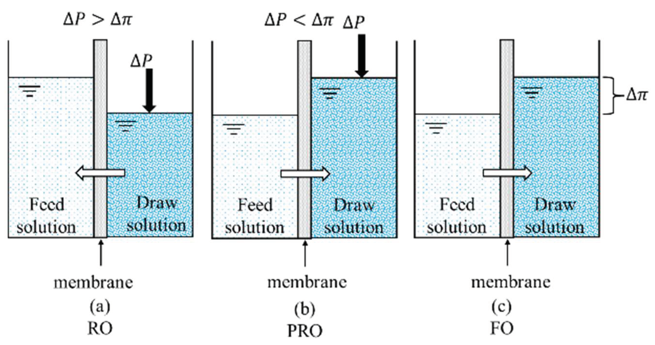
2.1. Basic Principles of FO Water Treatment
2.2. Advantages of FO Water Treatment
3. Major Issues Related to FO
3.1. Concentration Polarization
3.2. Membrane Fouling
3.3. Reverse Solute Flux
4. Advances in FO Draw Solutes/Solutions
4.1. Gaseous Draw Solutes
4.2. Inorganic-Based Draw Solutes
4.3. Organic-Based Draw Solutes
4.4. MNP-Based Draw Solutes
4.5. Hydrogel Solutes
5. Advances in FO Membranes
5.1. CA Membranes
5.2. TFC Membranes
5.3. PBI Membranes
5.4. AQP Membranes
6. Sustainability of FO Water Treatment
6.1. Continuous Development of High-Tech FO Membranes
6.2. Long-Term Exploration of Draw Solutions
6.3. Ongoing Research on Fouling
6.4. Reasonable Utilization of Hybrid Systems
7. Conclusions
Author Contributions
Funding
Institutional Review Board Statement
Informed Consent Statement
Data Availability Statement
Acknowledgments
Conflicts of Interest
References
- Wang, Y.; Mei, X.; Ma, T.F.; Xue, C.J.; Wu, M.D.; Ji, M.; Li, Y.G. Green recovery of hazardous acetonitrile from high-salt chemical wastewater by pervaporation. J. Clean. Prod. 2018, 197, 742–749. [Google Scholar] [CrossRef]
- Shi, J.X.; Huang, W.P.; Han, H.J.; Xu, C.Y. Review on treatment technology of salt wastewater in coal chemical industry of China. Desalination 2020, 493, 114640. [Google Scholar] [CrossRef]
- Firouzjaei, M.D.; Seyedpour, S.F.; Aktij, S.A.; Giagnorio, M.; Bazrafshan, N.; Mollahosseini, A.; Samadi, F.; Ahmadalipour, S.; Firouzjaei, F.D.; Esfahani, M.R.; et al. Recent advances in functionalized polymer membranes for biofouling control and mitigation in forward osmosis. J. Membr. Sci. 2020, 596, 117604. [Google Scholar] [CrossRef]
- Valladares Linares, R.; Li, Z.; Sarp, S.; Bucs, S.S.; Amy, G.; Vrouwenvelder, J.S. Forward osmosis niches in seawater desalination and wastewater reuse. Water Res. 2014, 66, 122–139. [Google Scholar] [CrossRef]
- Dharupaneedi, S.P.; Nataraj, S.K.; Nadagouda, M.; Reddy, K.R.; Shukla, S.S.; Aminabhavi, T.M. Membrane-based separation of potential emerging pollutants. Sep. Purif. Technol. 2019, 210, 850–866. [Google Scholar] [CrossRef]
- Dutta, S.; Nath, K. Feasibility of forward osmosis using ultra low pressure RO membrane and Glauber salt as draw solute for wastewater treatment. J. Environ. Chem. Eng. 2018, 6, 5635–5644. [Google Scholar] [CrossRef]
- Elsaid, K.; Sayed, E.T.; Abdelkareem, M.A.; Mahmoud, M.S.; Ramadan, M.; Olabi, A.G. Environmental impact of emerging desalination technologies: A preliminary evaluation. J. Environ. Chem. Eng. 2020, 8, 104099. [Google Scholar] [CrossRef]
- Liu, D.; Liu, Q.Q.; Zhang, Y. Research Progress on Zero Discharge and Resource Utilization of Industrial High-Salt Wastewater. CLEAN-Soil Air Water 2021, 49, 2000410. [Google Scholar] [CrossRef]
- Ouyang, W.; Chen, T.; Shi, Y.; Tong, L.; Chen, Y.; Wang, W.; Yang, J.; Xue, J. Physico-chemical processes. Water Environ. Res 2019, 91, 1350–1377. [Google Scholar] [CrossRef] [Green Version]
- Mohsenpour, S.F.; Hennige, S.; Willoughby, N.; Adeloye, A.; Gutierrez, T. Integrating micro-algae into wastewater treatment: A review. Sci. Total Environ. 2020, 752, 142168. [Google Scholar] [CrossRef] [PubMed]
- Chai, W.S.; Tan, W.G.; Munawaroh, H.S.H.; Gupta, V.K.; Ho, S.H.; Show, P.L. Multifaceted roles of microalgae in the application of wastewater biotreatment: A review. Environ. Pollut. 2021, 269, 116236. [Google Scholar] [CrossRef]
- Ahmad, N.N.R.; Ang, W.L.; Leo, C.P.; Mohammad, A.W.; Hilal, N. Current advances in membrane technologies for saline wastewater treatment: A comprehensive review. Desalination 2021, 517, 115170. [Google Scholar] [CrossRef]
- Vinardell, S.; Astals, S.; Peces, M.; Cardete, M.A.; Fernandez, I.; Mata-Alvarez, J.; Dosta, J. Advances in anaerobic membrane bioreactor technology for municipal wastewater treatment: A 2020 updated review. Renew. Sustain. Energy Rev. 2020, 130, 109936. [Google Scholar] [CrossRef]
- Ezugbe, E.O.; Rathilal, S. Membrane Technologies in Wastewater Treatment: A Review. Membranes 2020, 10, 89. [Google Scholar] [CrossRef]
- Wei, Y.Y.; Liu, G.P.; Luo, J.Q.; Li, L.B.; Xu, Z. Novel membrane separation technologies and membrane processes. Front. Chem. Sci. Eng. 2021, 15, 717–719. [Google Scholar] [CrossRef]
- Lutchmiah, K.; Verliefde, A.R.D.; Roest, K.; Rietveld, L.C.; Cornelissen, E.R. Forward osmosis for application in wastewater treatment: A review. Water Res. 2014, 58, 179–197. [Google Scholar] [CrossRef]
- Suwaileh, W.; Pathak, N.; Shon, H.; Hilal, N. Forward osmosis membranes and processes: A comprehensive review of research trends and future outlook. Desalination 2020, 485, 114455. [Google Scholar] [CrossRef]
- Dou, P.J.; Zhao, S.W.; Xu, S.S.; Li, X.M.; He, T. Feasibility of osmotic dilution for recycling spent dialysate: Process performance, scaling, and economic evaluation. Water Res. 2019, 168, 115157. [Google Scholar] [CrossRef] [PubMed]
- Duong, H.C.; Ansari, A.J.; Nghiem, L.D.; Cao, H.T.; Vu, T.D.; Nguyen, T.P. Membrane Processes for the Regeneration of Liquid Desiccant Solution for Air Conditioning. Curr. Pollut. Rep. 2019, 5, 308–318. [Google Scholar] [CrossRef]
- Ibrar, I.; Altaee, A.; Zhou, J.L.; Naji, O.; Khanafer, D. Challenges and potentials of forward osmosis process in the treatment of wastewater. Crit. Rev. Environ. Sci. Technol. 2020, 50, 1339–1383. [Google Scholar] [CrossRef]
- Wang, J.L.; Liu, X.J. Forward osmosis technology for water treatment: Recent advances and future perspectives. J. Clean. Prod. 2020, 280, 124354. [Google Scholar] [CrossRef]
- Widjojo, N.; Chung, T.-S.; Weber, M.; Maletzko, C.; Warzelhan, V. A sulfonated polyphenylenesulfone (sPPSU) as the supporting substrate in thin film composite (TFC) membranes with enhanced performance for forward osmosis (FO). Chem. Eng. J. 2013, 220, 15–23. [Google Scholar] [CrossRef]
- Darvishmanesh, S.; Pethica, B.A.; Sundaresan, S. Forward osmosis using draw solutions manifesting liquid-liquid phase separation. Desalination 2017, 421, 23–31. [Google Scholar] [CrossRef]
- Tang, Y.Y.; Xu, J.; Chen, X.; Gao, C.J. Core of Forward Osmosis for Desalination—Forward Osmosis Membrane. Prog. Chem. 2015, 27, 818–830. [Google Scholar]
- Cath, T.; Childress, A.; Elimelech, M. Forward osmosis: Principles, applications, and recent developments. J. Membr. Sci. 2006, 281, 70–87. [Google Scholar] [CrossRef]
- Altaee, A.; Braytee, A.; Millar, G.J.; Naji, O. Energy efficiency of hollow fibre membrane module in the forward osmosis seawater desalination process. J. Membr. Sci. 2019, 587, 117165. [Google Scholar] [CrossRef]
- McGinnis, R.L.; Elimelech, M. Energy requirements of ammonia-carbon dioxide forward osmosis desalination. Desalination 2007, 207, 370–382. [Google Scholar] [CrossRef]
- Siagiana, U.W.R.; Raksajati, A.; Himma, N.F.; Khoiruddin, K.; Wenten, I.G. Membrane-based carbon capture technologies: Membrane gas separation vs. membrane contactor. J. Nat. Gas Sci. Eng. 2019, 67, 172–195. [Google Scholar] [CrossRef]
- McGinnis, R.L.; Hancock, N.T.; Nowosielski-Slepowron, M.S.; McGurgan, G.D. Pilot demonstration of the NH3/CO2 forward osmosis desalination process on high salinity brines. Desalination 2013, 312, 67–74. [Google Scholar] [CrossRef]
- Altaee, A.; Zhou, J.; Alanezi, A.A.; Zaragoza, G. Pressure retarded osmosis process for power generation: Feasibility, energy balance and controlling parameters. Appl. Energy 2017, 206, 303–311. [Google Scholar] [CrossRef]
- Ma, C.; Li, Q.; Dai, C.; Wang, L.; Zhao, B.; Zhang, Z.; Xue, S.; Tian, W. Pilot-scale study of forward osmosis for treating desulfurization wastewater. Water Sci. Technol. 2020, 82, 2857–2863. [Google Scholar] [CrossRef] [PubMed]
- Mi, B.; Elimelech, M. Organic fouling of forward osmosis membranes: Fouling reversibility and cleaning without chemical reagents. J. Membr. Sci. 2010, 348, 337–345. [Google Scholar] [CrossRef]
- Jiang, Y.Z.; Liu, C.Y.; Huang, A.S. EDTA-Functionalized Covalent Organic Framework for the Removal of Heavy-Metal Ions. ACS Appl. Mater. Interfaces 2019, 11, 32186–32191. [Google Scholar] [CrossRef]
- Zhang, Y.; Ren, T.T.; Tian, H.; Jin, B.B.; He, J.H. Hydrogel-Encapsulated Enzyme Facilitates Colorimetric Acute Toxicity Assessment of Heavy Metal Ions. ACS Appl. Mater. Interfaces 2018, 10, 26705–26712. [Google Scholar] [CrossRef] [PubMed]
- Vijayaraghavan, K.; Rangabhashiyam, S.; Ashokkumar, T.; Arockiaraj, J. Mono- and multi-component biosorption of lead(II), cadmium(II), copper(II) and nickel(II) ions onto coco-peat biomass. Sep. Sci. Technol. 2016, 51, 2725–2733. [Google Scholar] [CrossRef]
- Fang, X.; Li, J.; Li, X.; Pan, S.; Zhang, X.; Sun, X.; Shen, J.; Han, W.; Wang, L. Internal pore decoration with polydopamine nanoparticle on polymeric ultrafiltration membrane for enhanced heavy metal removal. Chem. Eng. J. 2017, 314, 38–49. [Google Scholar] [CrossRef]
- He, M.; Wang, L.; Zhang, Z.; Zhang, Y.; Zhu, J.; Wang, X.; Lv, Y.; Miao, R. Stable Forward Osmosis Nanocomposite Membrane Doped with Sulfonated Graphene Oxide@Metal–Organic Frameworks for Heavy Metal Removal. ACS Appl. Mater. Interfaces 2020, 12, 57102–57116. [Google Scholar] [CrossRef]
- Phuntsho, S.; Sahebi, S.; Majeed, T.; Lotfi, F.; Kim, J.E.; Shon, H.K. Assessing the major factors affecting the performances of forward osmosis and its implications on the desalination process. Chem. Eng. J. 2013, 231, 484–496. [Google Scholar] [CrossRef]
- Chen, C.H.; Qin, H. A Mathematical Modeling of the Reverse Osmosis Concentration Process of a Glucose Solution. Processes 2019, 7, 271. [Google Scholar] [CrossRef] [Green Version]
- Xiao, Y.H.; Xu, H.J.; Zhao, C.Y. Modeling the mass transfer process in membranes for carbon capture and separation with concentration polarization effect. Int. Commun. Heat Mass Transf. 2021, 126, 105396. [Google Scholar] [CrossRef]
- Ibrar, I.; Yadav, S.; Altaee, A.; Hawari, A.; Nguyen, V.; Zhou, J. A novel empirical method for predicting concentration polarization in forward osmosis for single and multicomponent draw solutions. Desalination 2020, 494, 114668. [Google Scholar] [CrossRef]
- Arjmandi, A.; Peyravi, M.; Arjmandi, M.; Altaee, A. Exploring the use of cheap natural raw materials to reduce the internal concentration polarization in thin-film composite forward osmosis membranes. Chem. Eng. J. 2020, 398, 125483. [Google Scholar] [CrossRef]
- McCutcheon, J.R.; Elimelech, M. Influence of concentrative and dilutive internal concentration polarization on flux behavior in forward osmosis. J. Membr. Sci. 2006, 284, 237–247. [Google Scholar] [CrossRef]
- Gray, G.T.; McCutcheon, J.R.; Elimelech, M. Internal concentration polarization in forward osmosis: Role of membrane orientation. Desalination 2006, 197, 1–8. [Google Scholar] [CrossRef]
- Kim, S.; Hoek, E.M.V. Modeling concentration polarization in reverse osmosis processes. Desalination 2005, 186, 111–128. [Google Scholar] [CrossRef]
- Al-Mutaz, I.S.; Alsubaie, F.M. Development of a mathematical model for the prediction of concentration polarization in reverse osmosis desalination processes. Desalination Water Treat. 2017, 71, 19–24. [Google Scholar] [CrossRef] [Green Version]
- Song, X.X.; Liu, Z.Y.; Sun, D.R.D.L. Nano Gives the Answer: Breaking the Bottleneck of Internal Concentration Polarization with a Nanofiber Composite Forward Osmosis Membrane for a High Water Production Rate. Adv. Mater. 2011, 23, 3256. [Google Scholar] [CrossRef]
- Zhou, Z.; Lee, J.Y.; Chung, T.-S. Thin film composite forward-osmosis membranes with enhanced internal osmotic pressure for internal concentration polarization reduction. Chem. Eng. J. 2014, 249, 236–245. [Google Scholar] [CrossRef]
- Liang, S.Q.; Wu, J.H.; Wang, C.; Zhao, X.X.; Wang, C.; Yang, X.; Huo, H.L.; Wang, T.; Geng, Z.; Wang, X.Z. Ultra-high selectivity self-supporting symmetric membrane for forward osmosis separation. Desalination 2022, 534, 115796. [Google Scholar] [CrossRef]
- Xiao, F.; Xiao, P.; Zhang, W.J.; Wang, D.S. Identification of key factors affecting the organic fouling on low-pressure ultrafiltration membranes. J. Membr. Sci. 2013, 447, 144–152. [Google Scholar] [CrossRef]
- Tow, E.W.; Rencken, M.M.; Lienhard, J.H. In situ visualization of organic fouling and cleaning mechanisms in reverse osmosis and forward osmosis. Desalination 2016, 399, 138–147. [Google Scholar] [CrossRef] [Green Version]
- Emadzadeh, D.; Lau, W.J.; Matsuura, T.; Hilal, N.; Ismail, A.F. The potential of thin film nanocomposite membrane in reducing organic fouling in forward osmosis process. Desalination 2014, 348, 82–88. [Google Scholar] [CrossRef]
- Nielsen, C.H. Biomimetic membranes for sensor and separation applications. Anal. Bioanal. Chem. 2009, 395, 697–718. [Google Scholar] [CrossRef] [PubMed]
- Phuntsho, S.; Shon, H.K.; Hong, S.; Lee, S.; Vigneswaran, S. A novel low energy fertilizer driven forward osmosis desalination for direct fertigation: Evaluating the performance of fertilizer draw solutions. J. Membr. Sci. 2011, 375, 172–181. [Google Scholar] [CrossRef]
- Wang, X.; Wang, H.; Xie, M. Secret underneath: Fouling of membrane support layer in anaerobic osmotic membrane bioreactor (AnOMBR). J. Membr. Sci. 2020, 614, 118530. [Google Scholar] [CrossRef]
- Shen, L.; Zhang, X.; Zuo, J.; Wang, Y. Performance enhancement of TFC FO membranes with polyethyleneimine modification and post-treatment. J. Membr. Sci. 2017, 534, 46–58. [Google Scholar] [CrossRef]
- Li, F.; Cheng, Q.X.; Tian, Q.; Yang, B.; Chen, Q.Y. Biofouling behavior and performance of forward osmosis membranes with bioinspired surface modification in osmotic membrane bioreactor. Bioresour. Technol. 2016, 211, 751–758. [Google Scholar] [CrossRef]
- Choi, H.G.; Son, M.; Yoon, S.; Celik, E.; Kang, S.; Park, H.; Park, C.H.; Choi, H. Alginate fouling reduction of functionalized carbon nanotube blended cellulose acetate membrane in forward osmosis. Chemosphere 2015, 136, 204–210. [Google Scholar] [CrossRef]
- Luo, W.; Xie, M.; Song, X.; Guo, W.; Ngo, H.H.; Zhou, J.L.; Nghiem, L.D. Biomimetic aquaporin membranes for osmotic membrane bioreactors: Membrane performance and contaminant removal. Bioresour. Technol. 2018, 249, 62–68. [Google Scholar] [CrossRef] [Green Version]
- Zou, S.; Gu, Y.; Xiao, D.; Tang, C.Y. The role of physical and chemical parameters on forward osmosis membrane fouling during algae separation. J. Membr. Sci. 2011, 366, 356–362. [Google Scholar] [CrossRef]
- Yong, J.S.; Phillip, W.A.; Elimelech, M. Coupled reverse draw solute permeation and water flux in forward osmosis with neutral draw solutes. J. Membr. Sci. 2012, 392–393, 9–17. [Google Scholar] [CrossRef]
- Lopes, G.H.; Ibaseta, N.; Guichardon, P.; Haldenwang, P. Effects of Solute Permeability on Permeation and Solute Rejection in Membrane Filtration. Chem. Eng. Technol. 2018, 41, 788–797. [Google Scholar] [CrossRef]
- Ge, Q.; Ling, M.; Chung, T.-S. Draw solutions for forward osmosis processes: Developments, challenges, and prospects for the future. J. Membr. Sci. 2013, 442, 225–237. [Google Scholar] [CrossRef]
- Qasim, M.; Mohammed, F.; Aidan, A.; Darwish, N.A. Forward osmosis desalination using ferric sulfate draw solute. Desalination 2017, 423, 12–20. [Google Scholar] [CrossRef]
- Kim, Y.; Lee, J.H.; Kim, Y.C.; Lee, K.H.; Park, I.S.; Park, S.-J. Operation and simulation of pilot-scale forward osmosis desalination with ammonium bicarbonate. Chem. Eng. Res. Des. 2015, 94, 390–395. [Google Scholar] [CrossRef]
- Dutta, S.; Nath, K. Dewatering of Brackish Water and Wastewater by an Integrated Forward Osmosis and Nanofiltration System for Direct Fertigation. Arab. J. Sci. Eng. 2019, 44, 9977–9986. [Google Scholar] [CrossRef]
- Volpin, F.; Heo, H.; Hasan Johir, M.A.; Cho, J.; Phuntsho, S.; Shon, H.K. Techno-economic feasibility of recovering phosphorus, nitrogen and water from dilute human urine via forward osmosis. Water Res. 2019, 150, 47–55. [Google Scholar] [CrossRef]
- Yang, S.; Lee, S.; Hong, S. Enhancing the applicability of forward osmosis membrane process utilizing food additives as draw solutes. J. Membr. Sci. 2021, 638, 119705. [Google Scholar] [CrossRef]
- Bagheri, B.; Karimi-Jashni, A.; Zerafat, M.M. Application of molasses as draw solution in forward osmosis desalination for fertigation purposes. Environ. Technol. 2021, 42, 764–774. [Google Scholar] [CrossRef]
- Kim, J.; Kim, J.; Lim, J.; Hong, S. Evaluation of ethanol as draw solute for forward osmosis (FO) process of highly saline (waste)water. Desalination 2019, 456, 23–31. [Google Scholar] [CrossRef]
- Zhao, P.; Gao, B.; Xu, S.; Kong, J.; Ma, D.; Shon, H.K.; Yue, Q.; Liu, P. Polyelectrolyte-promoted forward osmosis process for dye wastewater treatment—Exploring the feasibility of using polyacrylamide as draw solute. Chem. Eng. J. 2015, 264, 32–38. [Google Scholar] [CrossRef]
- Shoorangiz, L.; Karimi-Jashni, A.; Azadi, F.; Zerafat, M.M. Water treatment by forward osmosis using novel D-Xylose coated magnetic nanoparticles as draw agent. Environ. Technol. 2021, 1–10. [Google Scholar] [CrossRef] [PubMed]
- Khazaie, F.; Shokrollahzadeh, S.; Bide, Y.; Sheshmani, S.; Shahvelayati, A.S. Forward osmosis using highly water dispersible sodium alginate sulfate coated-Fe3O4 nanoparticles as innovative draw solution for water desalination. Process Saf. Environ. Prot. 2021, 146, 789–799. [Google Scholar] [CrossRef]
- Zhang, H.; Li, J.; Cui, H.; Li, H.; Yang, F. Forward osmosis using electric-responsive polymer hydrogels as draw agents: Influence of freezing–thawing cycles, voltage, feed solutions on process performance. Chem. Eng. J. 2015, 259, 814–819. [Google Scholar] [CrossRef]
- Li, D.; Zhang, X.; Yao, J.; Simon, G.P.; Wang, H. Stimuli-responsive polymer hydrogels as a new class of draw agent for forward osmosis desalination. Chem. Commun. 2011, 47, 1710–1712. [Google Scholar] [CrossRef]
- Petrinic, I.; Stergar, J.; Buksek, H.; Drofenik, M.; Gyergyek, S.; Helix-Nielsen, C.; Ban, I.R.A. Superparamagnetic Fe3O4@CA Nanoparticles and Their Potential as Draw Solution Agents in Forward Osmosis. Nanomaterials 2021, 11, 2965. [Google Scholar] [CrossRef]
- Chaoui, I.; Abderafi, S.; Vaudreuil, S.; Bounahmidi, T. Water desalination by forward osmosis: Draw solutes and recovery methods—Review. Environ. Technol. Rev. 2019, 8, 25–46. [Google Scholar] [CrossRef]
- Tayel, A.; Nasr, P.; Sewilam, H. Forward osmosis desalination using pectin-coated magnetic nanoparticles as a draw solution. Clean Technol. Environ. Policy 2019, 21, 1617–1628. [Google Scholar] [CrossRef]
- Kim, Y.C.; Han, S.; Hong, S. A feasibility study of magnetic separation of magnetic nanoparticle for forward osmosis. Water Sci. Technol. 2011, 64, 469–476. [Google Scholar] [CrossRef]
- Khazaie, F.; Sheshmani, S.; Shokrollahzadeh, S.; Shahvelayati, A.S. Desalination of saline water via forward osmosis using magnetic nanoparticles covalently functionalized with citrate ions as osmotic agent. Environ. Technol. 2020, 43, 2113–2123. [Google Scholar] [CrossRef]
- Bai, H.; Liu, Z.; Sun, D.D. Highly water soluble and recovered dextran coated Fe3O4 magnetic nanoparticles for brackish water desalination. Sep. Purif. Technol. 2011, 81, 392–399. [Google Scholar] [CrossRef]
- Ling, M.M.; Chung, T.-S. Desalination process using super hydrophilic nanoparticles via forward osmosis integrated with ultrafiltration regeneration. Desalination 2011, 278, 194–202. [Google Scholar] [CrossRef]
- Li, D.; Zhang, X.; Yao, J.; Zeng, Y.; Simon, G.P.; Wang, H. Composite polymer hydrogels as draw agents in forward osmosis and solar dewatering. Soft Matter 2011, 7, 10048–10056. [Google Scholar] [CrossRef]
- Razmjou, A.; Simon, G.P.; Wang, H. Effect of particle size on the performance of forward osmosis desalination by stimuli-responsive polymer hydrogels as a draw agent. Chem. Eng. J. 2013, 215–216, 913–920. [Google Scholar] [CrossRef]
- Akther, N.; Sodiq, A.; Giwa, A.; Daer, S.; Arafat, H.A.; Hasan, S.W. Recent advancements in forward osmosis desalination: A review. Chem. Eng. J. 2015, 281, 502–522. [Google Scholar] [CrossRef]
- Sahebi, S.; Shon, H.K.; Phuntsho, S.; Ramavandi, B. Fabricating robust thin film composite membranes reinforced on woven mesh backing fabric support for pressure assisted and forward osmosis: A dataset. Data Brief 2018, 21, 364–370. [Google Scholar] [CrossRef]
- Ahmad, N.A.; Goh, P.S.; Abdul Karim, Z.; Ismail, A.F. Thin Film Composite Membrane for Oily Waste Water Treatment: Recent Advances and Challenges. Membranes 2018, 8, 86. [Google Scholar] [CrossRef] [Green Version]
- Shokrgozar Eslah, S.; Shokrollahzadeh, S.; Moini Jazani, O.; Samimi, A. Forward osmosis water desalination: Fabrication of graphene oxide-polyamide/polysulfone thin-film nanocomposite membrane with high water flux and low reverse salt diffusion. Sep. Sci. Technol. 2017, 53, 573–583. [Google Scholar] [CrossRef]
- Arena, J.T.; Chwatko, M.; Robillard, H.A.; McCutcheon, J.R. pH Sensitivity of Ion Exchange through a Thin Film Composite Membrane in Forward Osmosis. Environ. Sci. Technol. Lett. 2015, 2, 177–182. [Google Scholar] [CrossRef]
- Wei, J.; Qiu, C.; Tang, C.Y.; Wang, R.; Fane, A.G. Synthesis and characterization of flat-sheet thin film composite forward osmosis membranes. J. Membr. Sci. 2011, 372, 292–302. [Google Scholar] [CrossRef]
- Shibuya, M.; Park, M.J.; Lim, S.; Phuntsho, S.; Matsuyama, H.; Shon, H.K. Novel CA/PVDF nanofiber supports strategically designed via coaxial electrospinning for high performance thin-film composite forward osmosis membranes for desalination. Desalination 2018, 445, 63–74. [Google Scholar] [CrossRef]
- Lakra, R.; Balakrishnan, M.; Basu, S. Development of cellulose acetate-chitosan-metal organic framework forward osmosis membrane for recovery of water and nutrients from wastewater. J. Environ. Chem. Eng. 2021, 9, 105882. [Google Scholar] [CrossRef]
- Ren, J.; McCutcheon, J.R. A new commercial thin film composite membrane for forward osmosis. Desalination 2014, 343, 187–193. [Google Scholar] [CrossRef]
- Ahn, H.R.; Tak, T.M.; Kwon, Y.-N. Preparation and applications of poly vinyl alcohol (PVA) modified cellulose acetate (CA) membranes for forward osmosis (FO) processes. Desalination Water Treat. 2013, 53, 1–7. [Google Scholar] [CrossRef]
- Nguyen, T.P.N.; Yun, E.-T.; Kim, I.-C.; Kwon, Y.-N. Preparation of cellulose triacetate/cellulose acetate (CTA/CA)-based membranes for forward osmosis. J. Membr. Sci. 2013, 433, 49–59. [Google Scholar] [CrossRef]
- Song, H.-m.; Zhu, L.-j.; Zeng, Z.-x.; Xue, Q.-j. High performance forward osmosis cellulose acetate (CA) membrane modified by polyvinyl alcohol and polydopamine. J. Polym. Res. 2018, 25, 159. [Google Scholar] [CrossRef]
- Zyaie, J.; Sheikhi, M.; Baniasadi, J.; Sahebi, S.; Mohammadi, T. Assessment of a Thermally Modified Cellulose Acetate Forward-Osmosis Membrane Using Response Surface Methodology. Chem. Eng. Technol. 2018, 41, 1706–1715. [Google Scholar] [CrossRef]
- Tiraferri, A.; Yip, N.Y.; Phillip, W.A.; Schiffman, J.D.; Elimelech, M. Relating performance of thin-film composite forward osmosis membranes to support layer formation and structure. J. Membr. Sci. 2011, 367, 340–352. [Google Scholar] [CrossRef] [Green Version]
- Arena, J.T.; McCloskey, B.; Freeman, B.D.; McCutcheon, J.R. Surface modification of thin film composite membrane support layers with polydopamine: Enabling use of reverse osmosis membranes in pressure retarded osmosis. J. Membr. Sci. 2011, 375, 55–62. [Google Scholar] [CrossRef]
- Ma, N.; Wei, J.; Liao, R.; Tang, C.Y. Zeolite-polyamide thin film nanocomposite membranes: Towards enhanced performance for forward osmosis. J. Membr. Sci. 2012, 405–406, 149–157. [Google Scholar] [CrossRef]
- Huang, L.; Bui, N.-N.; Meyering, M.T.; Hamlin, T.J.; McCutcheon, J.R. Novel hydrophilic nylon 6,6 microfiltration membrane supported thin film composite membranes for engineered osmosis. J. Membr. Sci. 2013, 437, 141–149. [Google Scholar] [CrossRef]
- Emadzadeh, D.; Lau, W.J.; Matsuura, T.; Rahbari-Sisakht, M.; Ismail, A.F. A novel thin film composite forward osmosis membrane prepared from PSf–TiO2 nanocomposite substrate for water desalination. Chem. Eng. J. 2014, 237, 70–80. [Google Scholar] [CrossRef]
- Ren, J.; McCutcheon, J.R. Polyacrylonitrile supported thin film composite hollow fiber membranes for forward osmosis. Desalination 2015, 372, 67–74. [Google Scholar] [CrossRef] [Green Version]
- Faria, A.F.; Liu, C.; Xie, M.; Perreault, F.; Nghiem, L.D.; Ma, J.; Elimelech, M. Thin-film composite forward osmosis membranes functionalized with graphene oxide–silver nanocomposites for biofouling control. J. Membr. Sci. 2017, 525, 146–156. [Google Scholar] [CrossRef]
- Jonidi Jafari, A.; Saeedi-Jurkuyeh, A. Synthesis of thin-film composite forward osmosis membranes for removing organic micro-pollutants from aqueous solutions. Water Supply 2019, 19, 1160–1166. [Google Scholar]
- Zhao, W.; Liu, H.; Liu, Y.; Jian, M.; Gao, L.; Wang, H.; Zhang, X. Thin-Film Nanocomposite Forward-Osmosis Membranes on Hydrophilic Microfiltration Support with an Intermediate Layer of Graphene Oxide and Multiwall Carbon Nanotube. ACS Appl. Mater. Interfaces 2018, 10, 34464–34474. [Google Scholar] [CrossRef]
- Chang, H.M.; Chen, S.S.; Cai, Z.S.; Chang, W.S.; Ray, S.S.; Nguyen, N.C.; Li, C.W.; Paswan, M. Iodide recovery and boron removal from thin-film transistor liquid crystal display wastewater through forward osmosis. J. Clean. Prod. 2020, 258, 120587. [Google Scholar] [CrossRef]
- Li, Z.; Wang, Y.; Han, M.; Wang, D.; Han, S.; Liu, Z.; Zhou, N.; Shang, R.; Xie, C. Graphene Oxide Incorporated Forward Osmosis Membranes With Enhanced Desalination Performance and Chlorine Resistance. Front. Chem. 2019, 7, 877. [Google Scholar] [CrossRef]
- Saeedi-Jurkuyeh, A.; Jonidi Jafari, A.; Kalantary, R.R.; Esrafili, A. Preparation of a thin-film nanocomposite forward osmosis membrane for the removal of organic micro-pollutants from aqueous solutions. Environ. Technol. 2021, 42, 3011–3024. [Google Scholar] [CrossRef]
- Akther, N.; Ali, S.M.; Phuntsho, S.; Shon, H. Surface modification of thin-film composite forward osmosis membranes with polyvinyl alcohol–graphene oxide composite hydrogels for antifouling properties. Desalination 2020, 491, 114591. [Google Scholar] [CrossRef]
- Hajiaghaee, S.F.; Bozorg, A.; Norouzi, M. Forward osmosis performance of thin film composite membrane composed of electrospun polysulfone fiber coated by Fe3O4/fCNT-embedded polyamide active layer. Korean J. Chem. Eng. 2022. [Google Scholar] [CrossRef]
- Huang, J.J.; Mei, X.; Han, J.; Yao, L.; Chen, S.H.; You, X.F.; Liao, Y. Impacts of hydrophobic, hydrophilic, superhydrophobic and superhydrophilic nanofibrous substrates on the thin film composite forward osmosis membranes. J. Environ. Chem. Eng. 2021, 10, 106958. [Google Scholar] [CrossRef]
- Kahrizi, M.; Gonzales, R.R.; Kong, L.X.; Matsuyama, H.; Lu, P.; Lin, J.Y.; Zhao, S.F. Significant roles of substrate properties in forward osmosis membrane performance: A review. Desalination 2022, 528, 115615. [Google Scholar] [CrossRef]
- Jamnongkan, T.; Mongkholrattanasit, R.; Wattanakornsiri, A.; Wachirawongsakorn, P.; Takatsuka, Y.; Hara, T. Green adsorbents for copper (II) biosorption from waste aqueous solution based on hydrogel-beads of biomaterials. S. Afr. J. Chem. Eng. 2021, 35, 14–22. [Google Scholar] [CrossRef]
- Wang, K.Y.; Chung, T.-S. Polybenzimidazole nanofiltration hollow fiber for cephalexin separation. AICHE J. 2006, 52, 1363–1377. [Google Scholar] [CrossRef]
- Wang, K.Y.; Chung, T.-S.; Qin, J.-J. Polybenzimidazole (PBI) nanofiltration hollow fiber membranes applied in forward osmosis process. J. Membr. Sci. 2007, 300, 6–12. [Google Scholar] [CrossRef]
- Wang, K.Y.; Yang, Q.; Chung, T.-S.; Rajagopalan, R. Enhanced forward osmosis from chemically modified polybenzimidazole (PBI) nanofiltration hollow fiber membranes with a thin wall. Chem. Eng. Sci. 2009, 64, 1577–1584. [Google Scholar] [CrossRef]
- Flanagan, M.F.; Escobar, I.C. Novel charged and hydrophilized polybenzimidazole (PBI) membranes for forward osmosis. J. Membr. Sci. 2013, 434, 85–92. [Google Scholar] [CrossRef]
- Chen, S.C.; Su, J.; Fu, F.J.; Mi, B.; Chung, T.S. Gypsum (CaSO4.2H2O) Scaling on Polybenzimidazole and Cellulose Acetate Hollow Fiber Membranes under Forward Osmosis. Membranes 2013, 3, 354–374. [Google Scholar] [CrossRef] [Green Version]
- Fu, F.-J.; Zhang, S.; Sun, S.-P.; Wang, K.-Y.; Chung, T.-S. POSS-containing delamination-free dual-layer hollow fiber membranes for forward osmosis and osmotic power generation. J. Membr. Sci. 2013, 443, 144–155. [Google Scholar] [CrossRef]
- Chen, S.C.; Fu, X.Z.; Chung, T.-S. Fouling behaviors of polybenzimidazole (PBI)–polyhedral oligomeric silsesquioxane (POSS)/polyacrylonitrile (PAN) hollow fiber membranes for engineering osmosis processes. Desalination 2014, 335, 17–26. [Google Scholar] [CrossRef]
- Aiba, M.; Tokuyama, T.; Matsumoto, H.; Tomioka, H.; Higashihara, T.; Ueda, M. Semipermeable membranes based on polybenzimidazole: Simultaneous improvement in water flux and salt rejection by facile cross-linking. Desalination 2016, 395, 1–7. [Google Scholar] [CrossRef]
- Daer, S.; Akther, N.; Wei, Q.; Shon, H.K.; Hasan, S.W. Influence of silica nanoparticles on the desalination performance of forward osmosis polybenzimidazole membranes. Desalination 2020, 491, 114441. [Google Scholar] [CrossRef]
- Wang, C.; Li, Y.M. Permeation of greywater constituents in an aquaporin based biomimetic forward osmosis membrane process: Experimental performance and modeling. J. Chem. Technol. Biotechnol. 2019, 94, 1567–1575. [Google Scholar] [CrossRef]
- Liang, Z.X.; Yun, Y.B.; Wang, M.X.; Liu, G.C.; Lu, P.; Yang, W.; Li, C.L. Performance evaluation of interfacial polymerisation-fabricated aquaporin-based biomimetic membranes in forward osmosis. RSC Adv. 2019, 9, 10715–10726. [Google Scholar] [CrossRef] [PubMed] [Green Version]
- Li, X.; Loh, C.H.; Wang, R.; Widjajanti, W.; Torres, J. Fabrication of a robust high-performance FO membrane by optimizing substrate structure and incorporating aquaporin into selective layer. J. Membr. Sci. 2017, 525, 257–268. [Google Scholar] [CrossRef]
- Xie, M.; Luo, W.; Guo, H.; Nghiem, L.D.; Tang, C.Y.; Gray, S.R. Trace organic contaminant rejection by aquaporin forward osmosis membrane: Transport mechanisms and membrane stability. Water Res. 2018, 132, 90–98. [Google Scholar] [CrossRef] [Green Version]
- Madsen, H.T.; Bajraktari, N.; Hélix-Nielsen, C.; Van der Bruggen, B.; Søgaard, E.G. Use of biomimetic forward osmosis membrane for trace organics removal. J. Membr. Sci. 2015, 476, 469–474. [Google Scholar] [CrossRef]
- Behboudi, A.; Ghiasi, S.; Mohammadi, T.; Ulbricht, M. Preparation and characterization of asymmetric hollow fiber polyvinyl chloride (PVC) membrane for forward osmosis application. Sep. Purif. Technol. 2021, 270, 118801. [Google Scholar] [CrossRef]
- Tang, C.Y.; Zhao, Y.; Wang, R.; Helix-Nielsen, C.; Fane, A.G. Desalination by biomimetic aquaporin membranes: Review of status and prospects. Desalination 2013, 308, 34–40. [Google Scholar] [CrossRef]
- Zhao, Y.; Qiu, C.Q.; Li, X.S.; Vararattanavech, A.; Shen, W.M.; Torres, J.; Helix-Nielsen, C.; Wang, R.; Hu, X.; Fane, A.G.; et al. Synthesis of robust and high-performance aquaporin-based biomimetic membranes by interfacial polymerization-membrane preparation and RO performance characterization. J. Membr. Sci. 2012, 423, 422–428. [Google Scholar] [CrossRef]
- Mikhaylova, M.; Kim, D.K.; Berry, C.C.; Zagorodni, A.; Toprak, M.; Curtis, A.S.G.; Muhammed, M. BSA immobilization on amine-functionalized superparamagnetic iron oxide nanoparticles. Chem. Mater. 2004, 16, 2344–2354. [Google Scholar] [CrossRef]
- Zhang, R.; Liu, Y.; He, M.; Su, Y.; Zhao, X.; Elimelech, M.; Jiang, Z. Antifouling membranes for sustainable water purification: Strategies and mechanisms. Chem. Soc. Rev. 2016, 45, 5888–5924. [Google Scholar] [CrossRef] [PubMed]
- Feria-Diaz, J.J.; Lopez-Mendez, M.C.; Rodriguez-Miranda, J.P.; Sandoval-Herazo, L.C.; Correa-Mahecha, F. Commercial Thermal Technologies for Desalination of Water from Renewable Energies: A State of the Art Review. Processes 2021, 9, 262. [Google Scholar] [CrossRef]
- Nassrullah, H.; Anis, S.F.; Hashaikeh, R.; Hilal, N. Energy for desalination: A state-of-the-art review. Desalination 2020, 491, 114569. [Google Scholar] [CrossRef]
- Long, Q.; Jia, Y.; Li, J.; Yang, J.; Liu, F.; Zheng, J.; Yu, B. Recent Advance on Draw Solutes Development in Forward Osmosis. Processes 2018, 6, 165. [Google Scholar] [CrossRef] [Green Version]
- Suwaileh, W.; Johnson, D.; Jones, D.; Hilal, N. An integrated fertilizer driven forward osmosis- renewables powered membrane distillation system for brackish water desalination: A combined experimental and theoretical approach. Desalination 2019, 471, 114126. [Google Scholar] [CrossRef]
- Seo, J.; Kim, Y.M.; Chae, S.H.; Lim, S.J.; Park, H.; Kim, J.H. An optimization strategy for a forward osmosis-reverse osmosis hybrid process for wastewater reuse and seawater desalination: A modeling study. Desalination 2019, 463, 40–49. [Google Scholar] [CrossRef]
- Kim, J.E.; Phuntsho, S.; Chekli, L.; Hong, S.; Ghaffour, N.; Leiknes, T.; Choi, J.Y.; Shon, H.K. Environmental and economic impacts of fertilizer drawn forward osmosis and nanofiltration hybrid system. Desalination 2017, 416, 76–85. [Google Scholar] [CrossRef]
- Kujawska, A.; Kiełkowska, U.; Atisha, A.; Yanful, E.; Kujawski, W. Comparative analysis of separation methods used for the elimination of pharmaceuticals and personal care products (PPCPs) from water—A critical review. Sep. Purif. Technol. 2022, 290, 120797. [Google Scholar] [CrossRef]
- Pramanik, B.K.; Islam, M.A.; Asif, M.B.; Roychand, R.; Pramanik, S.K.; Shah, K.; Bhuiyan, M.; Hai, F. Emerging investigator series: Phosphorus recovery from municipal wastewater by adsorption on steelmaking slag preceding forward osmosis: An integrated process. Environ. Sci. Water Res. Technol. 2020, 6, 1559–1567. [Google Scholar] [CrossRef]
- Zhao, X.; Liu, C. Enhancing the forward osmosis performance via the mesoporous silica hollow spheres assisted fast adsorption-diffusion process. Mater. Lett. 2019, 234, 347–350. [Google Scholar] [CrossRef]
- Li, L.; Wang, X.; Xie, M.; Wang, H.; Li, X.; Ren, Y. EDTA-based adsorption layer for mitigating FO membrane fouling via in situ removing calcium binding with organic foulants. J. Membr. Sci. 2019, 578, 95–102. [Google Scholar] [CrossRef]
- Zhang, W.; Wen, Y.; Wu, M.; Zhang, J.; Qian, G. A heterostructure membrane with natural-light photocatalytic activity. Mater. Today Commun. 2020, 24, 101175. [Google Scholar] [CrossRef]
- Hafiz, M.A.; Hawari, A.H.; Das, P.; Khan, S.; Altaee, A. Comparison of dual stage ultrafiltration and hybrid ultrafiltration-forward osmosis process for harvesting microalgae (Tetraselmis sp.) biomass. Chem. Eng. Process. Process Intensif. 2020, 157, 108112. [Google Scholar] [CrossRef]


| Year | Draw Solutes/Solutions | Type | FO Performance | References |
|---|---|---|---|---|
| 2015 | Ammonium hydrogencarbonate (NH4HCO3) | Gaseous | WRR: 99.9%. | [65] |
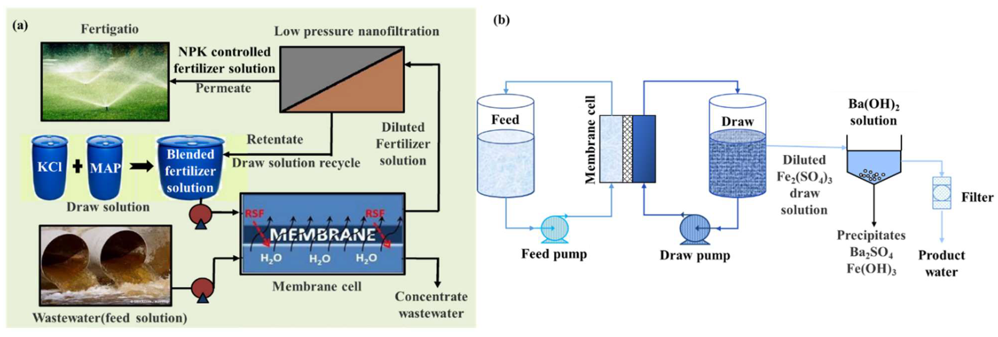
| 2019 | Inorganic fertilizers (KCl and NH4PO3) | Inorganic-based | WRR: >90%. | [66] |
| 2011 | Fertilizers (KCl, NaNO3, NH4Cl, and (NH4)2SO4) | Inorganic-based | —— | [54] |
| 2019 | Mg(NO3)2 6H2O | Inorganic-based | 93% P recovery; 50% N recovery. | [67] |
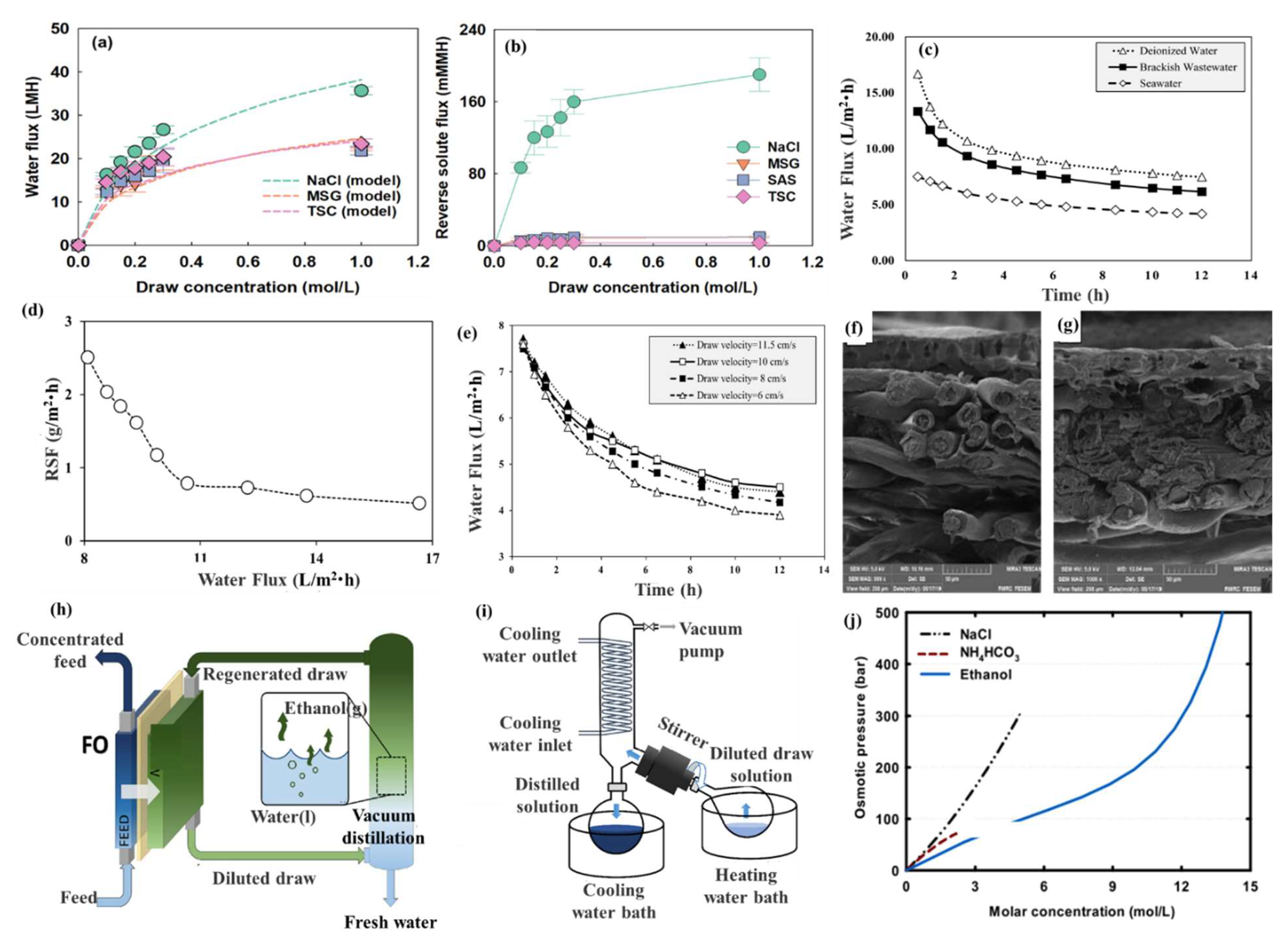
| 2017 | Iron(III) sulfate | Inorganic-based | WF: 3.75 L/m2·h for brackish water; WF: 1.61 L/m2·h for seawater. | [64] |
| 2021 | Food additives (monosodium glutamate (MSG), saccharin (SAS), and trisodium citrate (TSC)) | Organic-based | WF: up to about 20 L/m2·h for all the draw solutes. | [68] |
| 2021 | Molasses | Organic-based | WF: 16.7 L/m2·h for deionized water; WF: 13.3 L/m2·h for brackish wastewater; WF: 7.5 L/m2·h for seawater. | [69] |
| 2019 | Ethanol | Organic-based | —— | [70] |
| 2015 | Polyacrylamide | Organic-based | —— | [71] |
| 2021 | d-xylose-coated MNPs | MNP-based | WF: 2.98 L/m2·h. | [72] |
| 2021 | Fe3O4 nanoparticles with sodium alginate (SA) | MNP-based | WF: 13.8 L/m2·h. | [73] |
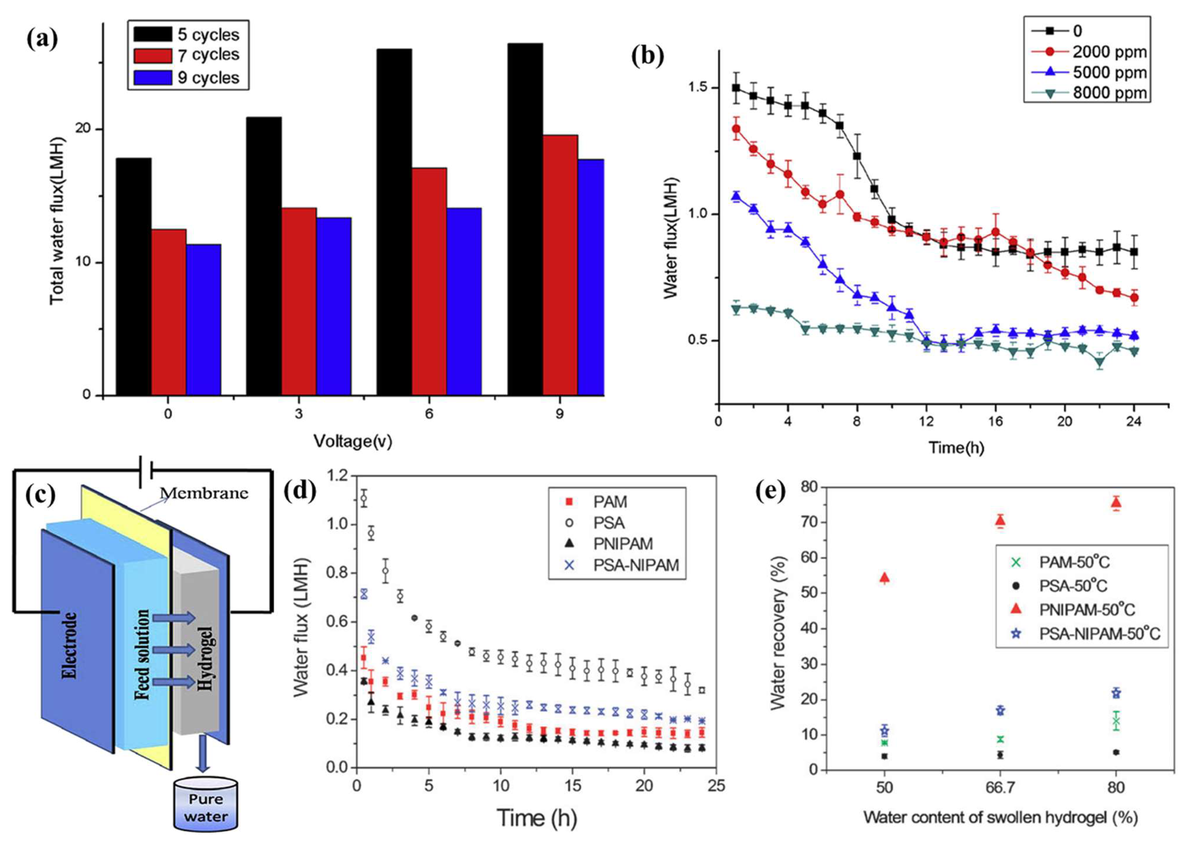
| 2015 | Electro-responsive polymer hydrogels | Hydrogel | WF: 26.47 L/m2·h. | [74] |
| 2011 | Ionic polymer hydrogel | Hydrogel | WF: lower than 1 L/m2·h. | [75] |
| Year | Membranes | Materials | Preparation Methods | Membrane Performance | References |
|---|---|---|---|---|---|
| 2013 | PVA-coated flat-sheet CA | PVA; CA | Phase inversion | WF: improved 20% compared with pure CA; SR: not changed. | [94] |
| 2013 | CTA/CA | CTA; CA | Immersion precipitation | WF: 10.39 L/m2·h, RSF: 0.084 mol NaCl/m2·h (FS: Milli-Q water; DS: 1 M NaCl); WF: 9.27 L/m2·h, RSF: 0.248 mol KBr /m2·h (FS: Milli-Q water; DS: 1 M KBr); lower membrane fouling. | [95] |
| 2015 | fCNT-CA | fCNT; CA | Phase inversion | WF: 50% higher than the unmodified CA; advanced alginate fouling resistance. | [58] |
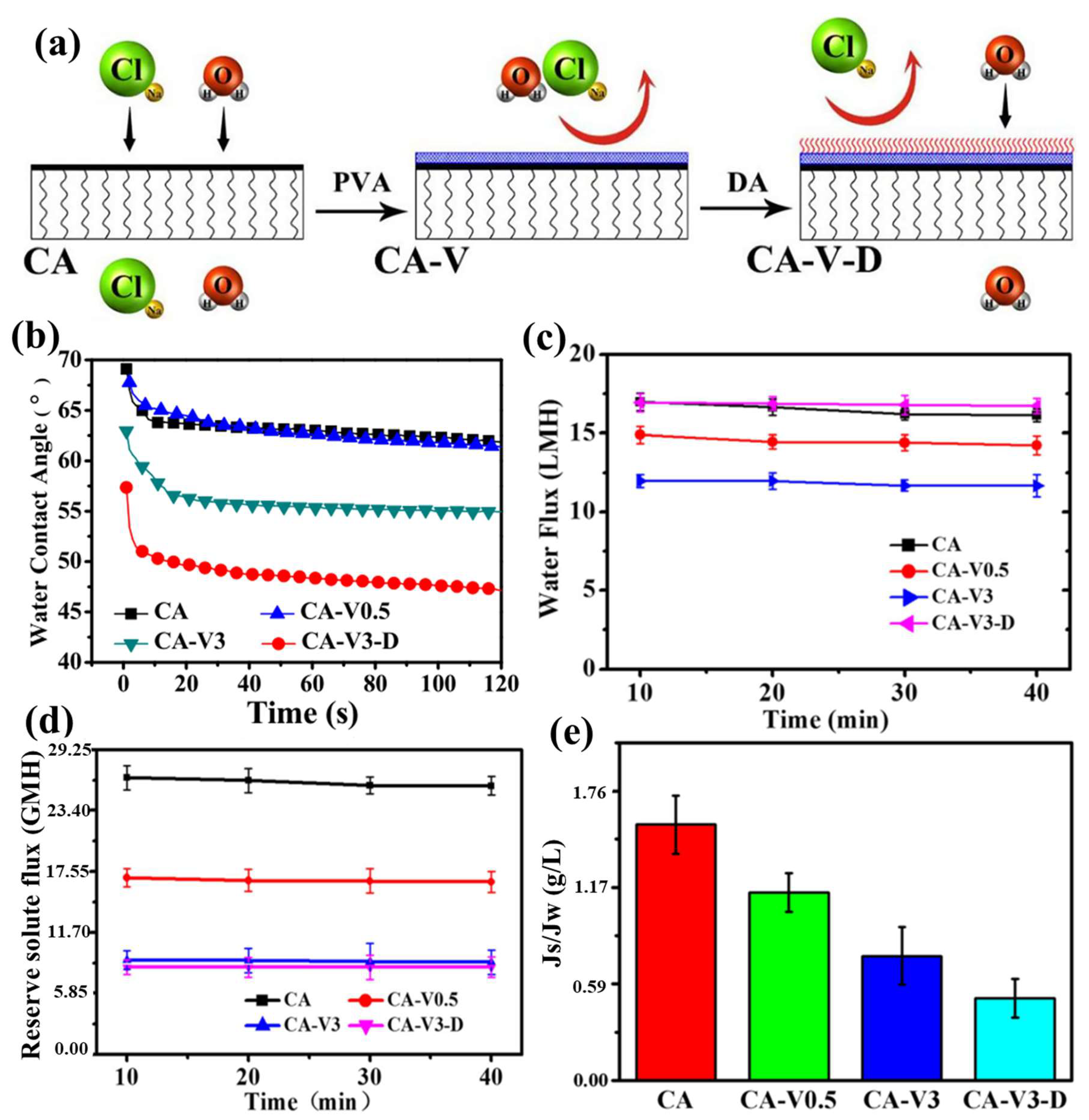
| 2018 | CA modified with PVA and PDA | PVA; PDA; CA | Phase inversion | WF: 16.72 L/m2·h, RSF: 0.14 mol NaCl/m2·h, Js/Jw: 3 times lower than that of bare CA (FS: DI water; DS: 2.0 M NaCl). | [96] |
| 2018 | Flat-sheet CA | CA | Phase inversion via immersion precipitation | WF: 21.75 L/m2·h, RSF: 5.88 g/m2·h; WF: 42.25 L/m2·h, RSF: 17.66 g/m2·h (Prediction based on Box–Behnken design). | [97] |
| Year | Membranes | Materials | Preparation Methods | Membrane Performance | References |
|---|---|---|---|---|---|
| 2011 | TFC | PSf support; PA active layer | Phase separation and interfacial polymerization | WF: 4–25 L/m2·h, SR: over 95.5% (DS: 1 M NaCl). | [98] |
| 2011 | flat-sheet TFC | Porous PSf substrates, PA rejection layers | Phase inversion and interfacial polymerization | WF: 54 L/m2·h, 50% higher than the commercial CTA-HW, (DS: 2 M NaCl). | [90] |
| 2011 | TFC modified with PDA | BW30, SW30-XLE; PET fabric layer; Psu | —— | WF: a two-fold increase for the SW30-XLE but a reduction for the BW30; an 8–15-fold increase compared to the control data | [99] |
| 2012 | Zeolite-PA TFN; Zeolite-PA TFC | PSf substrates; PA active layer; NaY zeolite nanoparticles. | Phase inversion and interfacial polymerization | WF: 80% increase compared to the pure TFC (DS: 0.5 M NaCl;FS: 1 M NaCl). | [100] |
| 2013 | TFC supported by nylon 6,6 MF membrane | nylon 6,6 MF membrane support; Poly(piperazinamide) or PA selective layer | Interfacial polymerization | WF: matched, RSF: 10-fold lower than the HTI CA. | [101] |
| 2014 | TiO2 TFN | PSf matrix; PA rejection layer; TiO2 nanoparticles | Phase inversion and interfacial polymerization | WF: improved by 86–93%. (DS: 1 M NaCl;FS: 2 M NaCl). | [102] |
| 2015 | PAN hollow-fiber supported TFC | Hydrophilic PAN hollow fiber support; PA active layer. | Dry-jet wet-spinning; interfacial polymerization | WF: 36.6 L/m2·h in PRO (DS: 1 M NaCl; FS: DI water). | [103] |
| 2016 | Anti-biofouling GO/Ag TFN | TFC; PA active layer; graphite powder; AgNO3 | —— | —— | [104] |
| 2017 | GO/PA TFN | PSf support; PA active layer; GO nanosheets | Phase inversion and interfacial polymerization | WF: 14.5 L/m2·h in FO, RSF: reduced up to 39%. | [36] |
| 2017 | PES/PDA UF | PES UF membrane; PA layer; PDA | Phase inversion | WF: 166 L/m2·h, SR: BSA rejection of 92.9%, 20.23 mg Pb/g, 17.01 mg Cd/g and 10.42 mg Cu/g. | [88] |
| 2018 | TFC | PSf polymer; PA active layer | Phase inversion and interfacial polymerization | SR: phenol rejection of 79% and benzene rejection of 90%. | [105] |
| 2018 | GO/MWCNT TFN | Nylon MF substrates; GO; MWCNT | Interfacial polymerization | WF: increase, RSF: reduce. | [106] |
| 2019 | HTI CTA, TFC-AQP flat-sheet membranes | —— | Direct purchase | SR: boron rejection of 98.4% and iodide rejection of 98.3% (DS: 2 M MgCl2). | [107] |
| 2020 | GO/PA-TFN | PSf Substrate; PA layer; Graphite | Phase inversion and interfacial polymerization | WF: increased 56.97% in AL-FS mode and 42.48% in AL-DS, SR: chlorine resistance 75 times better than baseline membrane (DS: 2 M NaCl). | [108] |
| 2020 | GO/PA-PEG/PSf TFN | PSf substrates; PA layer; GO; PEG. | Phase inversion and interfacial polymerization | WF: 34.3 L/m2·h SR: rejection rates of benzene, phenol, and toluene (97, 84, and 91%, respectively). | [109] |
| 2021 | GO/PVA hydrogel-coated PA TFC | PA TFC; GO; PVA. | Phase inversion and interfacial polymerization | WF: 29.3 L/m2·h; RSF: 13.8 g/m2·h; SRSF: 0.46 g/L. | [110] |
| 2022 | Fe3O4/fCNT-embedded PA TFC | polysulfone fibers; PA layer; Fe3O4 particle; fCNTs. | WF: 27.4 L/m2·h; SR: rejections of 90% and 94% for Na2SO4 and NaCl. | [111] |
| Year | Membranes | Materials | Preparation Methods | Membrane Performance | References |
|---|---|---|---|---|---|
| 2007 | PBI NF hollow-fiber membranes | hollow fiber; PBI dope | Dry-jet wet phase inversion and chemically cross-linking modification. | High water permeation flux and high rejection to divalent ions. | [116] |
| 2009 | PBI NF hollow-fiber membranes | PBI dope | Dry-jet wet phase inversion and chemically cross-linking modification. | High permeation flux and improved salt selectivity. | [117] |
| 2013 | PBI flat-sheet membranes | PBI dope | Dip-coating and phase inversion. | WF: increase, SR: increase, (DS: 2 M NH4HCO3; FS: 0.1 M NaCl). | [118] |
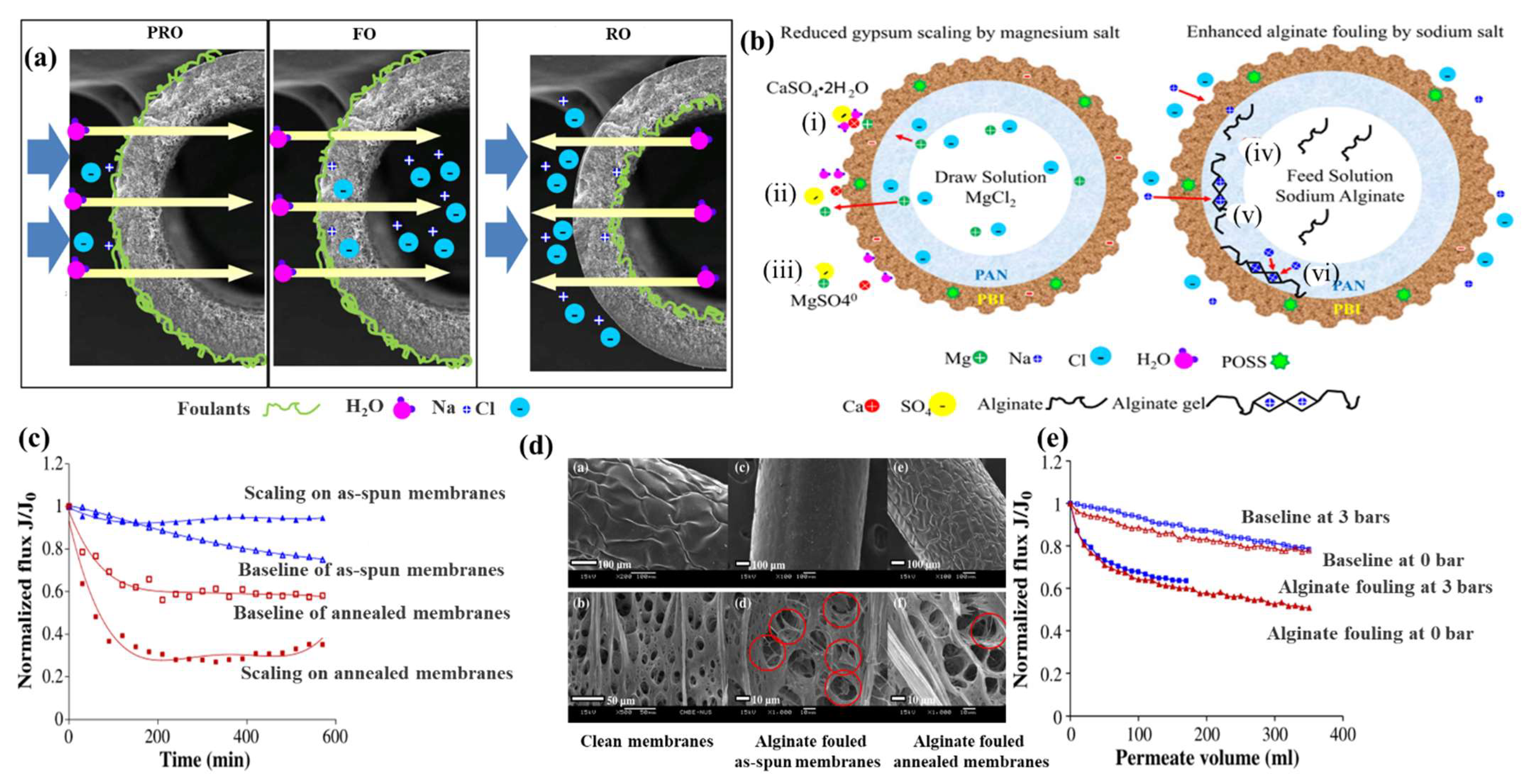
| 2013 | PBI-POSS/PAN | (1) CA; (2) PBI/PES; (3) PBI-POSS/PAN | —— | WF: 1.3% flux reduction, minimal scaling. | [119] |
| 2013 | PBI/POSS-PAN/PVP dual-layer hollow-fiber membranes | PBI/POSS outer layer; PAN/PVP inner layer | —— | WF: 31.37 L/m2·h (DS: 2.0 M MgCl2); power density: 2.47 W/m2 (DS: 1.0 M NaCl). | [120] |
| 2014 | PBI–POSS/PAN hollow-fiber membranes | Hollow-fiber membrane; POSS particles; PAN; PBI | —— | RSF: high, Lower fouling. | [121] |
| 2016 | Cross-linked N-substituted PBI membrane | N-butylsulfonated PBI; divinyl sulfone | Deprotonation and cross-linking modification. | WF: 22.1 L/m2·h, SR: 46% NaCl rejection. | [122] |
| 2020 | PBI/SiO2 flat-sheet membrane | Polyester fabric; PBI dope; silica nanoparticles | Non-solvent induced phase separation method. | WF: 16.9 L/m2·h (twofold higher than the pristine PBI (about 7.4 L/m2·h)). | [123] |
Publisher’s Note: MDPI stays neutral with regard to jurisdictional claims in published maps and institutional affiliations. |
© 2022 by the authors. Licensee MDPI, Basel, Switzerland. This article is an open access article distributed under the terms and conditions of the Creative Commons Attribution (CC BY) license (https://creativecommons.org/licenses/by/4.0/).
Share and Cite
Xu, Y.; Zhu, Y.; Chen, Z.; Zhu, J.; Chen, G. A Comprehensive Review on Forward Osmosis Water Treatment: Recent Advances and Prospects of Membranes and Draw Solutes. Int. J. Environ. Res. Public Health 2022, 19, 8215. https://doi.org/10.3390/ijerph19138215
Xu Y, Zhu Y, Chen Z, Zhu J, Chen G. A Comprehensive Review on Forward Osmosis Water Treatment: Recent Advances and Prospects of Membranes and Draw Solutes. International Journal of Environmental Research and Public Health. 2022; 19(13):8215. https://doi.org/10.3390/ijerph19138215
Chicago/Turabian StyleXu, Yang, Yingying Zhu, Zhen Chen, Jinyuan Zhu, and Geng Chen. 2022. "A Comprehensive Review on Forward Osmosis Water Treatment: Recent Advances and Prospects of Membranes and Draw Solutes" International Journal of Environmental Research and Public Health 19, no. 13: 8215. https://doi.org/10.3390/ijerph19138215
APA StyleXu, Y., Zhu, Y., Chen, Z., Zhu, J., & Chen, G. (2022). A Comprehensive Review on Forward Osmosis Water Treatment: Recent Advances and Prospects of Membranes and Draw Solutes. International Journal of Environmental Research and Public Health, 19(13), 8215. https://doi.org/10.3390/ijerph19138215