
Rapid Degradation of Chlortetracycline Using Hydrodynamic Cavitation with Hydrogen Peroxide


Abstract
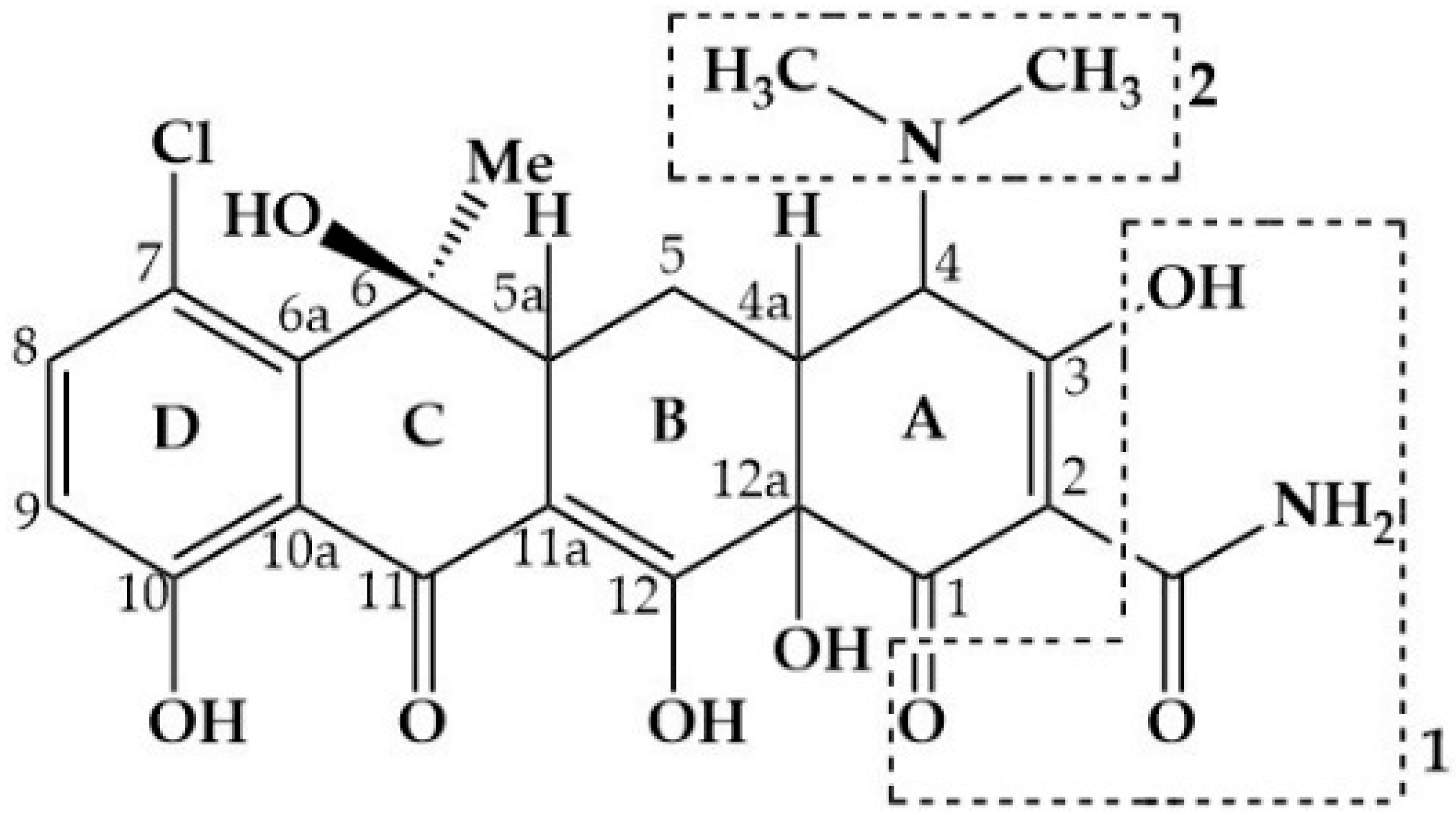
:1. Introduction
2. Materials and Methods
2.1. Chemicals
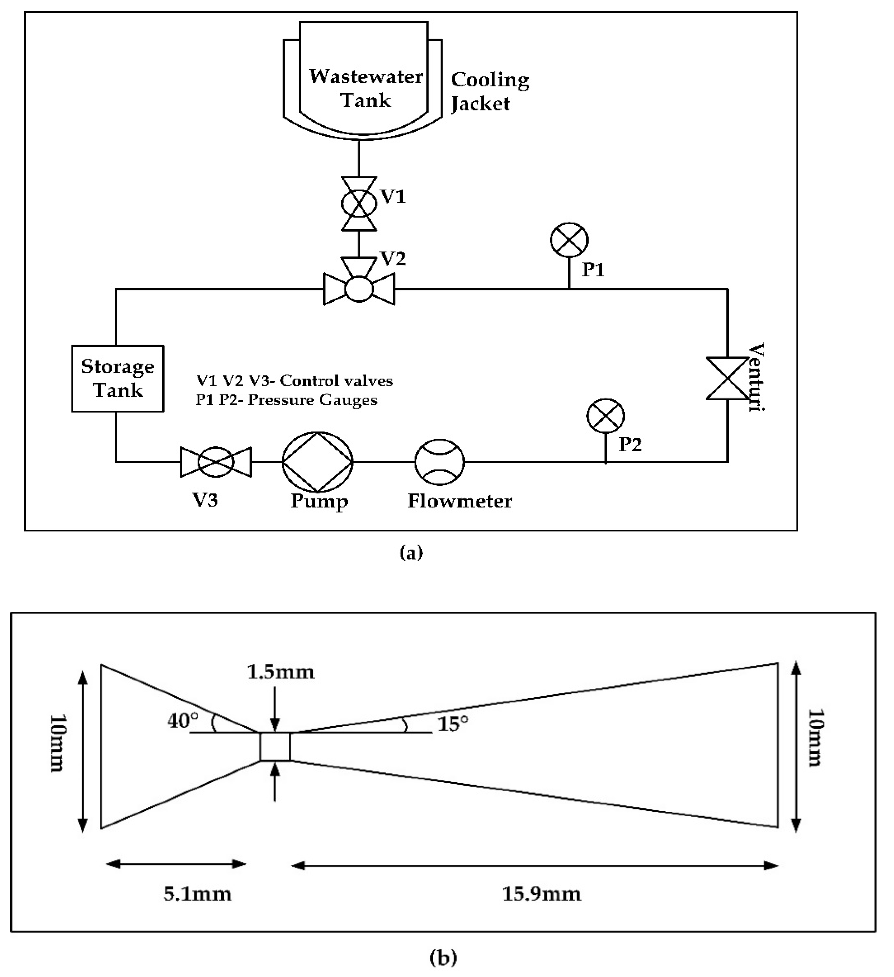
2.2. Experimental System
2.3. Experimental Procedure
2.4. Analytical Methods
2.5. Ecological Risk for Antibiotics in Water Samples
2.6. Energy Consumption Analysis
3. Results
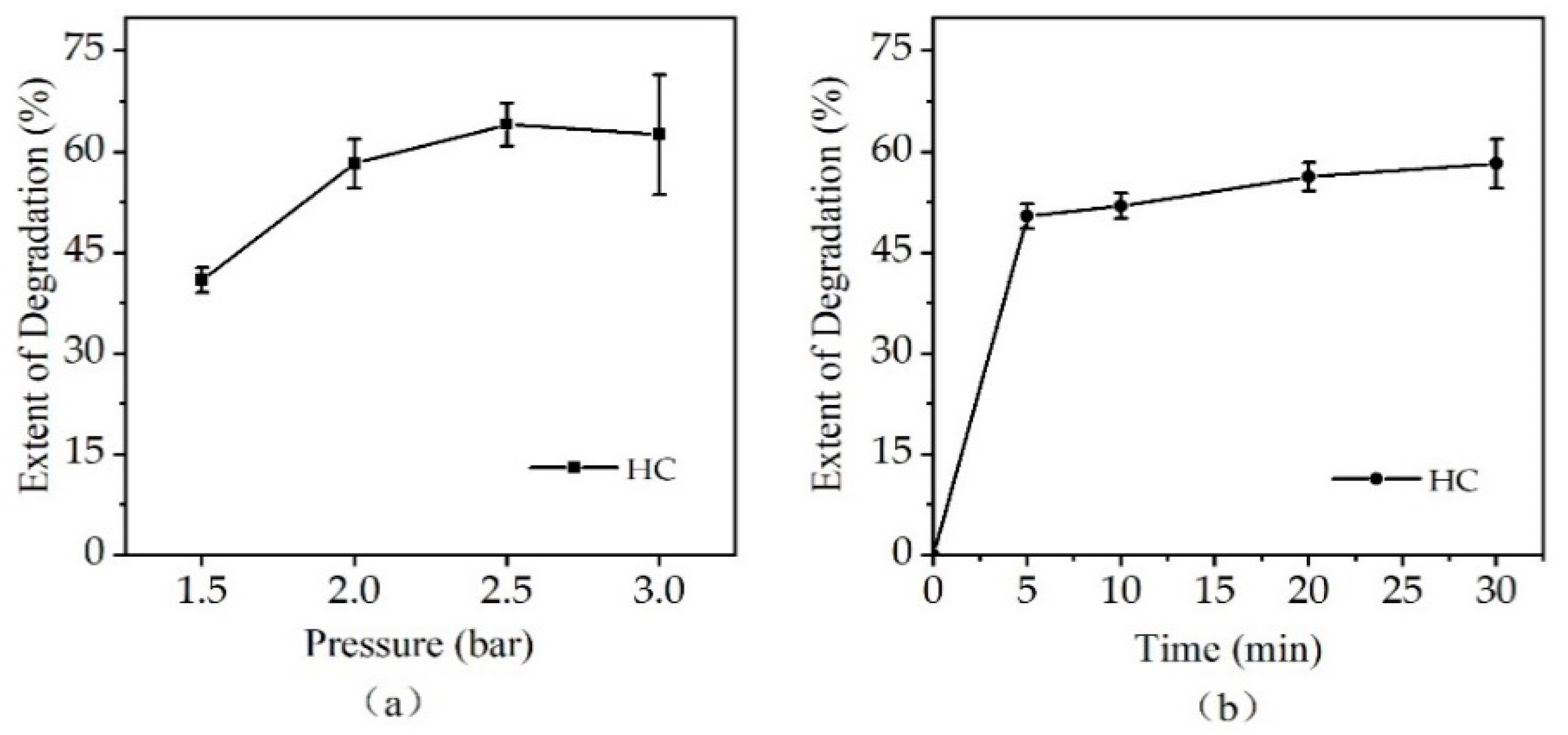
3.1. Extent of Degradation of CTC by HC Alone
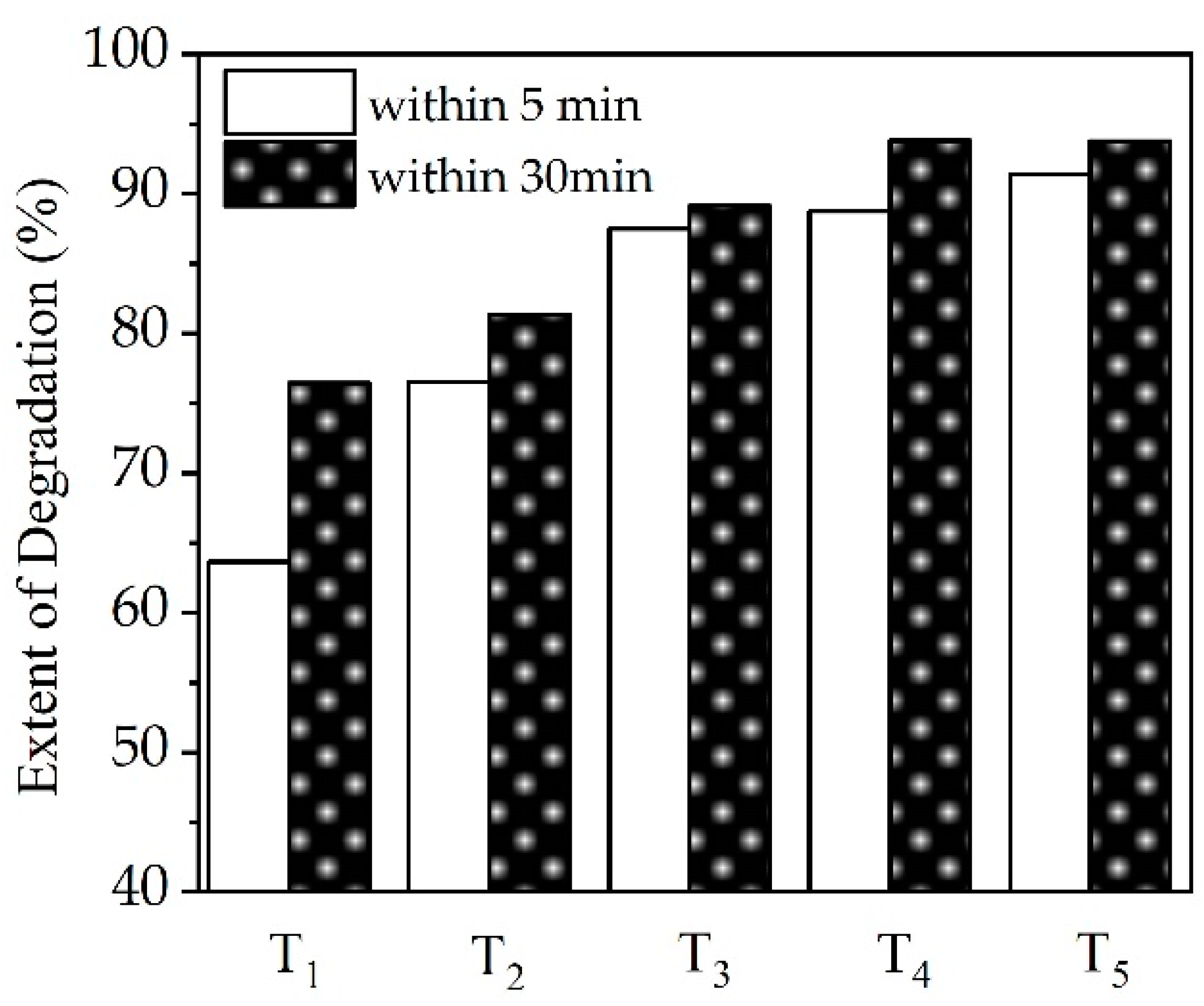
3.2. Extent of Degradation of CTC by HC Combined with Oxidants
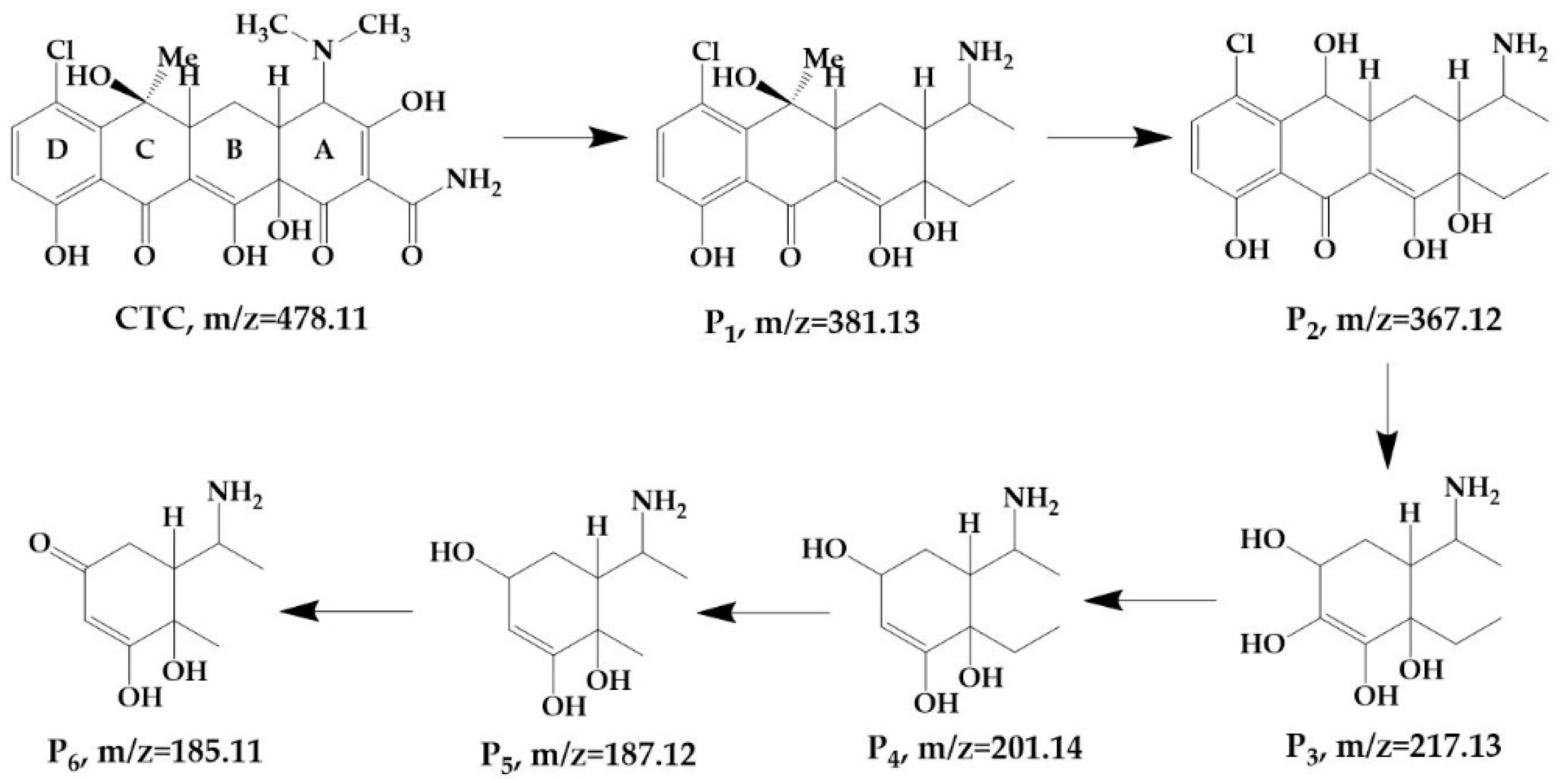
3.3. Product Identification and Pathways
3.3.1. Product Identification and Pathways Based on HC
3.3.2. Product Identification and Pathways via HC Combined with H2O2
3.4. Ecological Risk for Antibiotics in Water Samples
3.5. Energy Consumption Analysis
4. Discussion
4.1. Effect of Inlet Pressure
4.2. Effect of Oxidants
4.3. Possible Mechanisms of CTC Degradation
5. Conclusions
Supplementary Materials
Author Contributions
Funding
Institutional Review Board Statement
Informed Consent Statement
Data Availability Statement
Acknowledgments
Conflicts of Interest
References
- Song, Z.; Ma, Y.L.; Li, C.E. The residual tetracycline in pharmaceutical wastewater was effectively removed by using MnO2/graphene nanocomposite. Sci. Total Environ. 2019, 651, 580–590. [Google Scholar] [CrossRef] [PubMed]
- Hou, J.; Wang, C.; Mao, D.Q.; Luo, Y. The occurrence and fate of tetracyclines in two pharmaceutical wastewater treatment plants of Northern China. Environ. Sci. Pollut. Res. 2016, 23, 1722–1731. [Google Scholar] [CrossRef] [PubMed]
- Li, S.; Hu, J.Y. Photolytic and photocatalytic degradation of tetracycline: Effect of humic acid on degradation kinetics and mechanisms. J. Hazard. Mater. 2016, 318, 134–144. [Google Scholar] [CrossRef] [PubMed]
- Tian, Y.; Zou, J.; Feng, L.; Zhang, L.; Liu, Y. Chlorella vulgaris enhance the photodegradation of chlortetracycline in aqueous solution via extracellular organic matters (EOMs): Role of triplet state EOMs. Water Res. 2019, 149, 35–41. [Google Scholar] [CrossRef] [PubMed]
- Liao, X.B.; Zou, R.S.; Li, B.X.; Tong, T.L.; Xie, S.G.; Yuan, B.L. Biodegradation of chlortetracycline by acclimated microbiota. Process Saf. Environ. Prot. 2017, 109, 11–17. [Google Scholar] [CrossRef]
- Kong, W.; Gao, Y.; Yue, Q.; Li, Q.; Gao, B.; Kong, Y.; Wang, X.; Zhang, P.; Wang, Y. Performance optimization of CdS precipitated graphene oxide/polyacrylic acid composite for efficient photodegradation of chlortetracycline. J. Hazard. Mater. 2020, 388, 121780. [Google Scholar] [CrossRef]
- Badmus, K.O.; Tijani, J.; Massima, E.; Petrik, L. Treatment of persistent organic pollutants in wastewater using hydrodynamic cavitation in synergy with advanced oxidation process. Environ. Sci. Pollut. Res. 2018, 25, 7299–7314. [Google Scholar] [CrossRef] [Green Version]
- Daghrir, R.; Drogui, P.; Delegan, N.; El Khakani, M.A. Electrochemical degradation of chlortetracycline using N-doped Ti/TiO2 photoanode under sunlight irradiations. Water Res. 2013, 47, 6801–6810. [Google Scholar] [CrossRef]
- Sun, X.; Liu, S.; Zhang, X.; Tao, Y.; Boczkaj, G.; Yong Yoon, J.; Xuan, X. Recent advances in hydrodynamic cavitation-based pretreatments of lignocellulosic biomass for valorization. Bioresour. Technol. 2021, 345, 126251. [Google Scholar] [CrossRef]
- Thanekar, P.; Panda, M.; Gogate, P.R. Degradation of carbamazepine using hydrodynamic cavitation combined with advanced oxidation processes. Ultrason. Sonochem. 2018, 40, 567–576. [Google Scholar] [CrossRef]
- Cvetkovic, M.; Kompare, B.; Klemencic, A.K. Application of hydrodynamic cavitation in ballast water treatment. Environ. Sci. Pollut. Res. Int. 2015, 22, 7422–7438. [Google Scholar] [CrossRef] [PubMed]
- Barik, A.J.; Gogate, P.R. Hybrid treatment strategies for 2,4,6-trichlorophenol degradation based on combination of hydrodynamic cavitation and AOPs. Ultrason. Sonochem. 2018, 40, 383–394. [Google Scholar] [CrossRef] [PubMed]
- Sun, X.; You, W.B.; Xuan, X.X.; Ji, L.; Xu, X.; Wang, G.C.; Zhao, S.; Boczkaj, G.; Yoon, J.Y.; Chen, S.Y. Effect of the cavitation generation unit structure on the performance of an advanced hydrodynamic cavitation reactor for process intensifications. Chem. Eng. J. 2021, 412, 15. [Google Scholar] [CrossRef]
- Badmus, K.O.; Irakoze, N.; Adeniyi, O.R.; Petrik, L. Synergistic advance Fenton oxidation and hydrodynamic cavitation treatment of persistent organic dyes in textile wastewater. J. Environ. Chem. Eng. 2020, 8, 103521. [Google Scholar] [CrossRef]
- Pradhan, A.A.; Gogate, P.R. Removal of p-nitrophenol using hydrodynamic cavitation and Fenton chemistry at pilot scale operation. Chem. Eng. J. 2010, 156, 77–82. [Google Scholar] [CrossRef]
- Mishra, K.P.; Gogate, P.R. Intensification of degradation of Rhodamine B using hydrodynamic cavitation in the presence of additives. Sep. Purif. Technol. 2010, 75, 385–391. [Google Scholar] [CrossRef]
- Gogate, P.R.; Pandit, A.B. Application of Cavitational reactors for cell disruption for recovery of intracellular enzymes. J. Chem. Technol. Biotechnol. 2008, 83, 1083–1093. [Google Scholar] [CrossRef]
- Amin, L.P.; Gogate, P.R.; Burgess, A.E.; Bremner, D.H. Optimization of a hydrodynamic cavitation reactor using salicylic acid dosimetry. Chem. Eng. J. 2010, 156, 165–169. [Google Scholar] [CrossRef] [Green Version]
- Sun, X.; Yang, Z.; Wei, X.S.; Tao, Y.; Boczkaj, G.; Yoon, J.Y.; Xuan, X.X.; Chen, S.Y. Multi-objective optimization of the cavitation generation unit structure of an advanced rotational hydrodynamic cavitation reactor. Ultrason. Sonochem. 2021, 80, 10. [Google Scholar] [CrossRef]
- Petkovic, S.D.; Adnadjevic, B.K.; Jovanovic, J.D. A novel advanced technology for removal of phenol from wastewaters in a ventury reactor. Therm. Sci. 2019, 23, 1935–1942. [Google Scholar] [CrossRef] [Green Version]
- Wang, K.; Jin, R.Y.; Qiao, Y.N.; He, Z.D.; Wang, Y.; Wang, X.J. The removal of Rhodamine B by H2O2 or ClO2 combined with hydrodynamic cavitation. Water Sci. Technol. 2019, 80, 1571–1580. [Google Scholar] [CrossRef] [PubMed]
- Rajoriya, S.; Bargole, S.; Saharan, V.K. Degradation of a cationic dye (Rhodamine 6G) using hydrodynamic cavitation coupled with other oxidative agents: Reaction mechanism and pathway. Ultrason. Sonochem. 2017, 34, 183–194. [Google Scholar] [CrossRef] [PubMed]
- Rajoriya, S.; Bargole, S.; George, S.; Saharan, V.K. Treatment of textile dyeing industry effluent using hydrodynamic cavitation in combination with advanced oxidation reagents. J. Hazard. Mater. 2018, 344, 1109–1115. [Google Scholar] [CrossRef] [PubMed]
- Joshi, S.M.; Gogate, P.R. Intensification of industrial wastewater treatment using hydrodynamic cavitation combined with advanced oxidation at operating capacity of 70 L. Ultrason. Sonochem. 2019, 52, 375–381. [Google Scholar] [CrossRef]
- Gągol, M.; Soltani, R.D.C.; Przyjazny, A.; Boczkaj, G. Effective degradation of sulfide ions and organic sulfides in cavitation-based advanced oxidation processes (AOPs). Ultrason. Sonochem. 2019, 58, 104610. [Google Scholar] [CrossRef]
- Patil, P.N.; Bote, S.D.; Gogate, P.R. Degradation of imidacloprid using combined advanced oxidation processes based on hydrodynamic cavitation. Ultrason. Sonochem. 2014, 21, 1770–1777. [Google Scholar] [CrossRef]
- Li, G.; Yi, L.; Wang, J.; Song, Y. Hydrodynamic cavitation degradation of Rhodamine B assisted by Fe(3+)-doped TiO2: Mechanisms, geometric and operation parameters. Ultrason. Sonochem. 2020, 60, 104806. [Google Scholar] [CrossRef]
- Roy, K.; Moholkar, V.S. Sulfadiazine degradation using hybrid AOP of heterogeneous Fenton/persulfate system coupled with hydrodynamic cavitation. Chem. Eng. J. 2020, 386, 121294. [Google Scholar] [CrossRef]
- Mukherjee, A.; Mullick, A.; Moulik, S.; Roy, A. Oxidative degradation of emerging micropollutants induced by rotational hydrodynamic cavitating device: A case study with ciprofloxacin. J. Environ. Chem. Eng. 2021, 9, 105652. [Google Scholar] [CrossRef]
- European Commission. Technical Guidance Document on Risk Assessment, (TGD); Part II, Technical Report; European Commission (EC), 2003; pp. 1917–1942. Available online: https://echa.europa.eu/documents/10162/987906/tgdpart2_2ed_en.pdf/138b7b71-a069-428e-9036-62f4300b752f (accessed on 25 March 2022).
- Bagal, M.V.; Gogate, P.R. Degradation of 2,4-dinitrophenol using a combination of hydrodynamic cavitation, chemical and advanced oxidation processes. Ultrason. Sonochem. 2013, 20, 1226–1235. [Google Scholar] [CrossRef]
- Raut-Jadhav, S.; Saharan, V.K.; Pinjari, D.; Sonawane, S.; Saini, D.; Pandit, A. Synergetic effect of combination of AOP’s (hydrodynamic cavitation and H2O2) on the degradation of neonicotinoid class of insecticide. J. Hazard. Mater. 2013, 261, 139–147. [Google Scholar] [CrossRef] [PubMed]
- Gore, M.M.; Saharan, V.K.; Pinjari, D.V.; Chavan, P.V.; Pandit, A.B. Degradation of reactive orange 4 dye using hydrodynamic cavitation based hybrid techniques. Ultrason. Sonochem. 2014, 21, 1075–1082. [Google Scholar] [CrossRef] [PubMed]
- Saharan, V.K.; Badve, M.P.; Pandit, A.B. Degradation of Reactive Red 120 dye using hydrodynamic cavitation. Chem. Eng. J. 2011, 178, 100–107. [Google Scholar] [CrossRef]
- Wang, W.M.; Song, J.; Han, X. Schwertmannite as a new Fenton-like catalyst in the oxidation of phenol by H2O2. J. Hazard. Mater. 2013, 262, 412–419. [Google Scholar] [CrossRef] [PubMed]
- Mirzaei, A.; Chen, Z.; Haghighat, F.; Yerushalmi, L. Removal of pharmaceuticals from water by homo/heterogonous Fenton-type processes—A review. Chemosphere 2017, 174, 665–688. [Google Scholar] [CrossRef] [PubMed]
- Jin, Q.Q.; Chen, Q.; Kang, J.; Shen, J.M.; Guo, F.; Chen, Z.L. Fabrication of iron-dipicolinamide catalyst with Fe-N bonds for enhancing non-radical reactive species under alkaline Fenton process. Chemosphere 2020, 241, 11. [Google Scholar] [CrossRef] [PubMed]
- Tao, Y.; Cai, J.; Huai, X.; Liu, B. A novel antibiotic wastewater degradation technique combining cavitating jets impingement with multiple synergetic methods. Ultrason. Sonochem. 2018, 44, 36–44. [Google Scholar] [CrossRef]
- Wang, J.; Guo, Y.; Guo, P.; Yu, J.; Guo, W.; Wang, X. Degradation of reactive brilliant red K-2BP in water using a combination of swirling jet-induced cavitation and Fenton process. Sep. Purif. Technol. 2014, 130, 1–6. [Google Scholar] [CrossRef]
- Pulicharla, R.; Das, R.K.; Kaur Brar, S.; Drogui, P.; Surampalli, R.Y. Degradation kinetics of chlortetracycline in wastewater using ultrasonication assisted laccase. Chem. Eng. J. 2018, 347, 828–835. [Google Scholar] [CrossRef]
- Zhang, M.; Shi, Q.; Cheng, X.; Yang, J.; Liu, Z.; Chen, T.; Qu, Y.; Wang, J.; Xie, M.; Han, W. Accelerated generation of hydroxyl radical through surface polarization on BiVO4 microtubes for efficient chlortetracycline degradation. Chem. Eng. J. 2020, 400, 125871. [Google Scholar] [CrossRef]
- Pulicharla, R.; Brar, S.K.; Rouissi, T.; Auger, S.; Drogui, P.; Verma, M.; Surampalli, R.Y. Degradation of chlortetracycline in wastewater sludge by ultrasonication, Fenton oxidation, and ferro-sonication. Ultrason. Sonochem. 2017, 34, 332–342. [Google Scholar] [CrossRef] [PubMed]
- Li, T.; Ouyang, E. Case study on the application of salt-tolerant bacteria to the treatment of highly concentrated wastewater from pharmaceutical industry. Ind. Water Treat. 2019, 39, 96–99. [Google Scholar]
- Zhang, H.; Liu, W.; Jiang, H.; Yang, L.; Luo, L.; Song, S. Treatment of Pharmaceutical Wastewater Using Combined Fenton, Coagulating Sedimentation, Hydrolysis Acidification, and A/O Process. China Water Wastewater 2018, 34, 89–92. [Google Scholar]


| Inlet Pressure (bar) | Flow Rate (LPH) | Number of Entire Fluids Passes per Minute |
|---|---|---|
| 1.5 | 180 | 3 |
| 2.0 | 240 | 4 |
| 2.5 | 300 | 5 |
| 3.0 | 360 | 6 |
| Organism | PNEC (mg/L) | RQ |
|---|---|---|
| Green algae | 1.9 | 2.6 |
| Daphnid | 0.3 | 16.5 |
| Fish | 8.0 | 0.6 |
| Treatment Time (min) | Degradation Rate (%) | CTC Degraded (mg/L) | Power Density (kJ/L) | C. Y. (mg/J) |
|---|---|---|---|---|
| 5 | 88.7 | 71.0 | 792 | 9.0 × 10⁻⁵ |
| 10 | 88.7 | 71.0 | 792 | 9.0 × 10⁻⁵ |
| 20 | 91.0 | 72.8 | 792 | 9.2 × 10⁻⁵ |
| 30 | 93.8 | 75.0 | 792 | 9.5 × 10⁻⁵ |
Publisher’s Note: MDPI stays neutral with regard to jurisdictional claims in published maps and institutional affiliations. |
© 2022 by the authors. Licensee MDPI, Basel, Switzerland. This article is an open access article distributed under the terms and conditions of the Creative Commons Attribution (CC BY) license (https://creativecommons.org/licenses/by/4.0/).
Share and Cite
Meng, C.; Meng, M.; Sun, X.; Gu, C.; Zou, H.; Li, X. Rapid Degradation of Chlortetracycline Using Hydrodynamic Cavitation with Hydrogen Peroxide. Int. J. Environ. Res. Public Health 2022, 19, 4167. https://doi.org/10.3390/ijerph19074167
Meng C, Meng M, Sun X, Gu C, Zou H, Li X. Rapid Degradation of Chlortetracycline Using Hydrodynamic Cavitation with Hydrogen Peroxide. International Journal of Environmental Research and Public Health. 2022; 19(7):4167. https://doi.org/10.3390/ijerph19074167
Chicago/Turabian StyleMeng, Chen, Min Meng, Xun Sun, Congcong Gu, Huiyun Zou, and Xuewen Li. 2022. "Rapid Degradation of Chlortetracycline Using Hydrodynamic Cavitation with Hydrogen Peroxide" International Journal of Environmental Research and Public Health 19, no. 7: 4167. https://doi.org/10.3390/ijerph19074167