1. Introduction
Even though special moment-resistant frames (SMFs) can be considered a recent development in building codes, their use can be traced back to the first reports of the use of structural steel in building construction more than one century ago [
1].
At present, there is an increased demand for SMFs in civil construction. This is due to their good dissipation response to seismic events and their versatility in architectural applications. These frames impose smaller forces on foundations than other structural systems, which results in more economical foundation systems. Nonetheless, seismic provisions must be guaranteed in their design. This was widely discussed by different authors, for example, in the work of Andrade [
2], on the qualification of steel I-beam connections connected to column weak axis, Bustamante [
3], in his work on the qualification of a composite tubular SMF connection, Ceron [
4], on the prequalification of a beam-column moment welded connection with dog bone section reduction in the beam, Cheng et al. [
5], on the evaluation of the seismic performance of steel beams to concrete-filled steel tubular column connections, Ramirez [
6], in his work on the analysis of the inelastic behavior of a double T connection [
6], Schneider and Alostaz [
7], on the experimental analysis of connections to concrete-filled steel tubes, Sheet et al. [
8], on the experimental investigation of concrete-filled tubular (CFT) column-to-steel beam connections under cyclic loading, Shin et al. [
9], in their work on the behavior of welded CFT column to H-beam connections with external stiffeners, Torres [
10], on the qualification of a rigid metal connection I beam—composite column, and by Vallejo and Clement [
11] on the evaluation a steel beam’s rigid connection to a concrete-filled tubular column when submitted to dynamic load.
Since their inception, the methodology for the design and construction of SMFs has been constantly reviewed to consider the requirements of new construction projects [
12,
13]. This can be observed in the updates to building codes such as AISC 358-16 [
14] and AISC 341-16 [
15], in which the design philosophy has been updated to prevent failure induced by strong seismic events. In addition, a special focus is placed on the versatility of frames that can be used in multiple civil constructions, and whose design allows for significant damage during a strong earthquake [
16].
SMFs include three basic elements in their construction: beams, columns, and beam-column connections. A particular type of SMF uses a concrete-filled steel tubular (CFST) column. This setup is used extensively in architectural and industrial applications, mainly because of its load-bearing capacity under different loading conditions [
17]. In addition, the use of diaphragms is common since they provide adequate structural integrity [
17,
18].
Due to their multiple advantages for construction and assembly, a variety of SMFs are included in building codes, such as AISC 358. Nonetheless, due to the multiple options in the configuration of SMFs, some are not covered under building codes and must be tested according to the provisions included in AISC 341 [
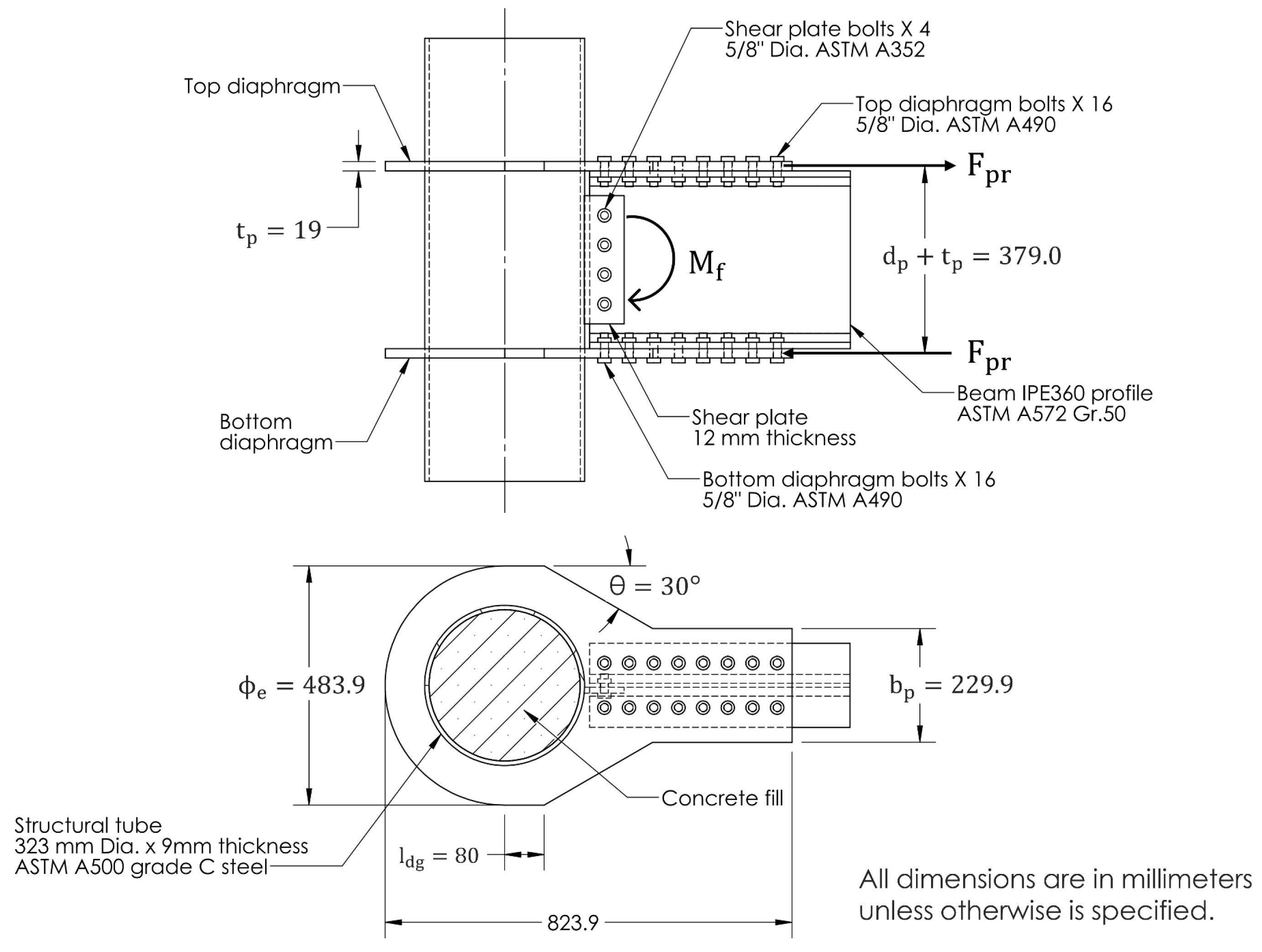
15]. This is the case of the connection analyzed in this work, which uses a concrete-filled steel tubular column connection and external diaphragms.
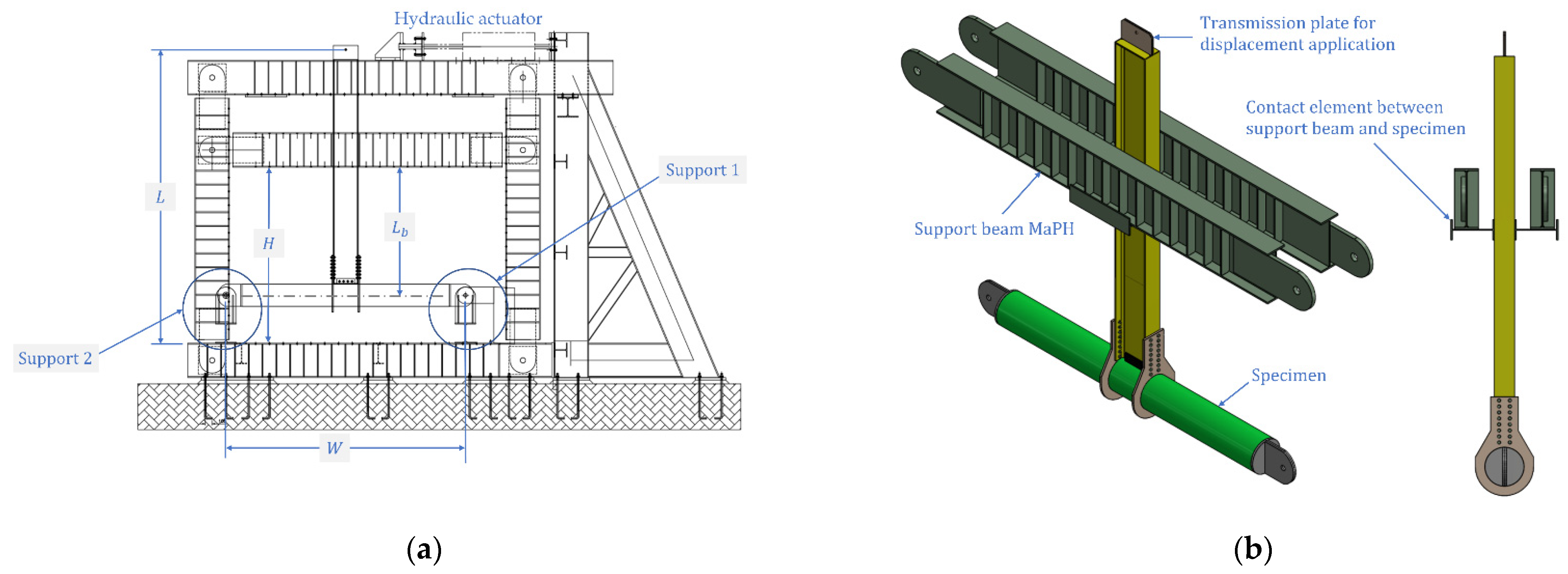
The experimental work presented by Ramírez et al. [
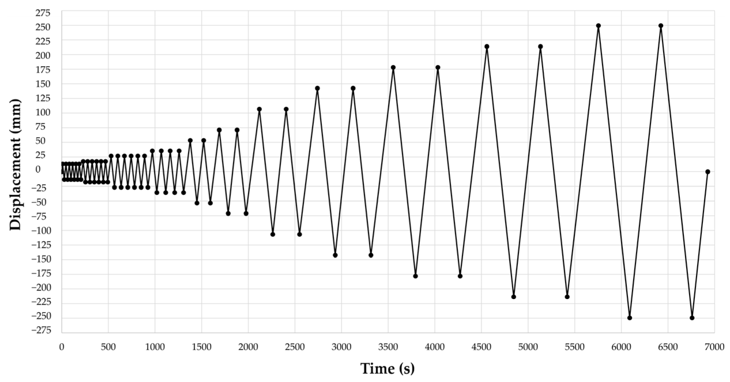
19] was aimed at the study and qualification of the connection modeled in this work. For this, an experimental test was conducted in accordance with the FEMA 350 standard for earthquake-resistant structures [
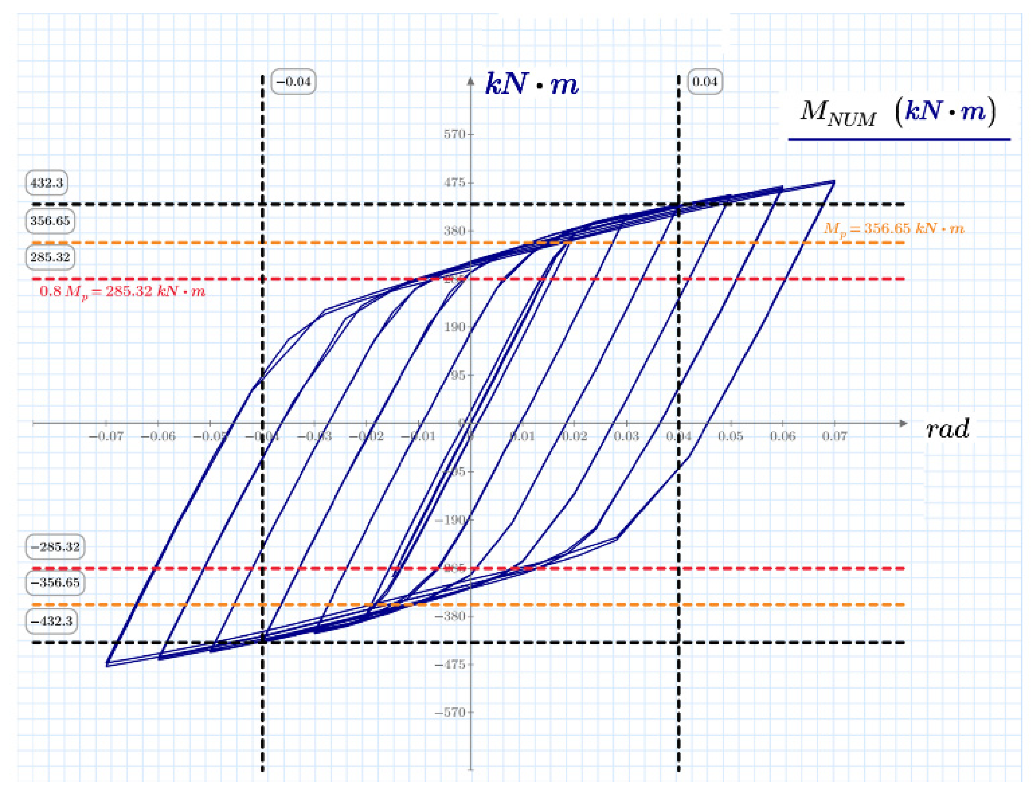
12]. The failure modes, hysteretic performance, strength and stiffness degradation, rigidity classification and energy dissipation were determined and analyzed. It was concluded in the experimental study that this connection exhibits large hysteretic loops and develops ductility and dissipation capacity. More importantly, the maximum rotation of the beam was 0.07 rad with a resistant moment above 80% of the beam capacity measured from the face of the column. Thus, the ductility design requirements for earthquake resistance were met according to the current regulations. A review of the experimental work conducted on different configurations of CFST column-to-steel beam connections to analyze their seismic behavior was also conducted by Ramirez et al. [
19].
Despite the good results obtained in the experimental tests presented by Ramírez et al. [
19] for the steel beam-to-concrete-filled steel tubular column connection using external diaphragms, there are multiple possibilities in the configuration of this type of connection. Testing these configurations will require the development of an expensive and time-consuming experimental test program. A numerical model is a key tool to tackle this issue, i.e., the numerical model can be used to conduct low-cost evaluation of the performance of a particular configuration or group of configurations. Moreover, if such a model can be simplified, it will be a convenient tool to provide fast and satisfactory answers for engineering design purposes.
Examples of the modeling efforts on different configurations of CFSTs can be found in the literature. For instance, Cheng, C.T. and Chung, L. [
5] developed an analytical nonlinear force–deformation model to simulate the shear transfer behavior in the panel zone of CFST beam-column connections. In this model, the authors considered the influence of the axial load on the shear transfer behavior. The model was validated with experimental tests conducted on five different types of CFST beam-column connections. It was observed that better ductility of connections occurred at higher axial loads. In addition, the predictions of the model were better for higher axial loads but showed a more conservative behavior for lower axial loads.
Shin et al. [
9] presented a numerical model to describe the behavior of CFT columns to H-beam welded moment connections with external T-stiffeners under cyclic loads. The model was based on the finite element method (FEM) and aided by the software ABAQUS. The model was evaluated by comparing the test results for displacement responses and the potential of failure modes. The authors reported good agreement in the prediction of the model. In addition, the model indicated that a properly designed T-stiffener leads to the formation of the plastic hinge in the beam section away from the column face.
Wu et al. [
20] developed a mechanical model to describe the theoretical equations to calculate the stiffness, yielding shear strength, and ultimate shear strength of the panel zone for a proposed new design of bolted beam-to-column connections for CFT. The model considers the behavior of steel and concrete elements as independent and accounts for the presence of holes in both steel and concrete elements. The model was validated with a series of cyclic loading experiments that were in close agreement with the experimental results. It was also shown that the proposed connection met the specifications for seismic resistance while presenting good energy dissipation capacity with plastic angular displacements of more than 5%.
Li et al. [
21] developed an analytical model to describe the seismic behavior of a connection for circular CFST column-to-steel beam composite structures. The connection was characterized by an extended endplate welded to a steel beam and bolted to a CFT column using high-strength steel rods. The model is based on the FEM and showed good agreement with experiments. The model was implemented using the object-oriented software framework OPENSEES and was validated against experimental tests. The tests showed that the connection exhibited good ductility and energy dissipation capability, meeting the requirements recommended by the AISC.
Tao et al. [
22] developed a numerical model based on the FEM to analyze the behavior of bolted end-plate joints for (CFST) columns, steel beams, and through-bolt connections. The model was validated with experimental tests conducted under lateral cyclic loading with horizontal displacements imposed at the top of the column. The proposed model showed satisfactory agreement with the experiments. In particular, the three typical stages, elastic, elastic–plastic and load descending, could be identified from the full range of the load–displacement skeleton curves. The model also captured the buckling effect of the beam flange and web in a satisfactory manner. The model was also used to compare the performance of the bolted joint with that of the counterpart with an external diaphragm.
Xu et al. [
23] developed a finite element model using ABAQUS to evaluate the seismic performance of a damage-tolerant steel frame. This type of frame is provided with a composite ultrahigh-performance concrete (UHPC) joint and friction damper applied at the beam-to-column connection. Pushover analysis and nonlinear dynamic analyses were carried out to compare the behavior of the proposed damage-tolerant steel frame against a conventional frame. The model results showed that, compared to the conventional frame, the deformation and the base shear force of the novel frame are significantly reduced. It was also concluded that the early yielding mechanism caused by the weak friction dampers can effectively improve the energy dissipation performance and damage control.
Wu et al. [
24] developed a finite element model in ABAQUS to describe the seismic performance of a steel-reinforced concrete column-steel beam composite joint (MPCJ). They analyzed three different beam-column connection types: bolted, welded, and bolted-welded. The connections were subjected to low-cycle reversed loading to investigate the elastic and elastoplastic development trends, failure characteristics, and seismic response. Based on the experimental results, it was concluded that the MPCJs exhibited stable hysteretic curves, reasonable strength and stiffness degradation and good ductility and energy dissipation performance. These results were used to validate the finite element model, which showed good agreement with the experiments. In addition, based on the experimental results and the numerical validation, the authors proposed simplified equations to calculate the flexural and shear-bearing capacity of MPCJs.
Rong et al. [
25] conducted an FEM-based analysis of the seismic performance of a steel frame with an external diaphragm joint between a CFST column and an H-shaped steel beam. The numerical model considered material and geometric nonlinearity. The model was validated with the hysteretic and skeleton curves obtained for a quasistatic test conducted to analyze the joint stiffness, beam-to-column stiffness ratio and concrete strength. Although the model was in good agreement with experiments, the authors reported that the numerical model had a plumper hysteretic curve and was more rigid than the experimental results. They attributed this to the initial defects of the material being ignored and the simplification of the weld. In addition, the authors reported that the model was in good agreement for the deformation and stress distribution.
Mou et al. [
26] conducted a numerical analysis to evaluate the seismic performance of a novel connection between a beam and a reinforced concrete-filled steel tube (RCFST) column. The connection was tested under cyclic loading to evaluate the failure modes, hysteretic performance, stiffness degradation, strength degradation, energy dissipation capacity, and strain responses. The authors compared the skeleton curves of the experiments and the numerical model. It was observed that the curves were in good agreement before the peak load. They attributed the mismatch beyond the peak load to the difficulty in simulating the behavior of bond-slip between steel parts and concrete parts and the cracking behavior of concrete. The authors also reported that the failure modes predicted by the model and observed experimentally were similar.
Li et al. [
27] proposed a numerical model based on the FEM to study the seismic performance of a novel U-shaped diaphragm connection designed to transfer the moment at beam ends in the frame with special-shaped CFST columns and steel beams. The model was verified by comparing the horizontal load-interstory drift hysteretic curves of the tests. Then, the model was used to analyze the influences of the U-shaped diaphragm size, tube thickness, and axial load ratio of the column. Based on the parametric analysis results, a mechanical model was proposed to calculate the yield strength and ultimate strength of U-shaped diaphragm connections. The authors reported good agreement between the strengths calculated by the mechanical model and the FEM-based model.
Previous research in the field highlights the relevance of developing numerical models that support the design and analysis of a particular portfolio of connections. Nonetheless, none of the models available in the literature can be used to study the seismic behavior of the steel beam-to-concrete-filled steel tubular column connection using external diaphragms qualified experimentally by Ramírez et al. [
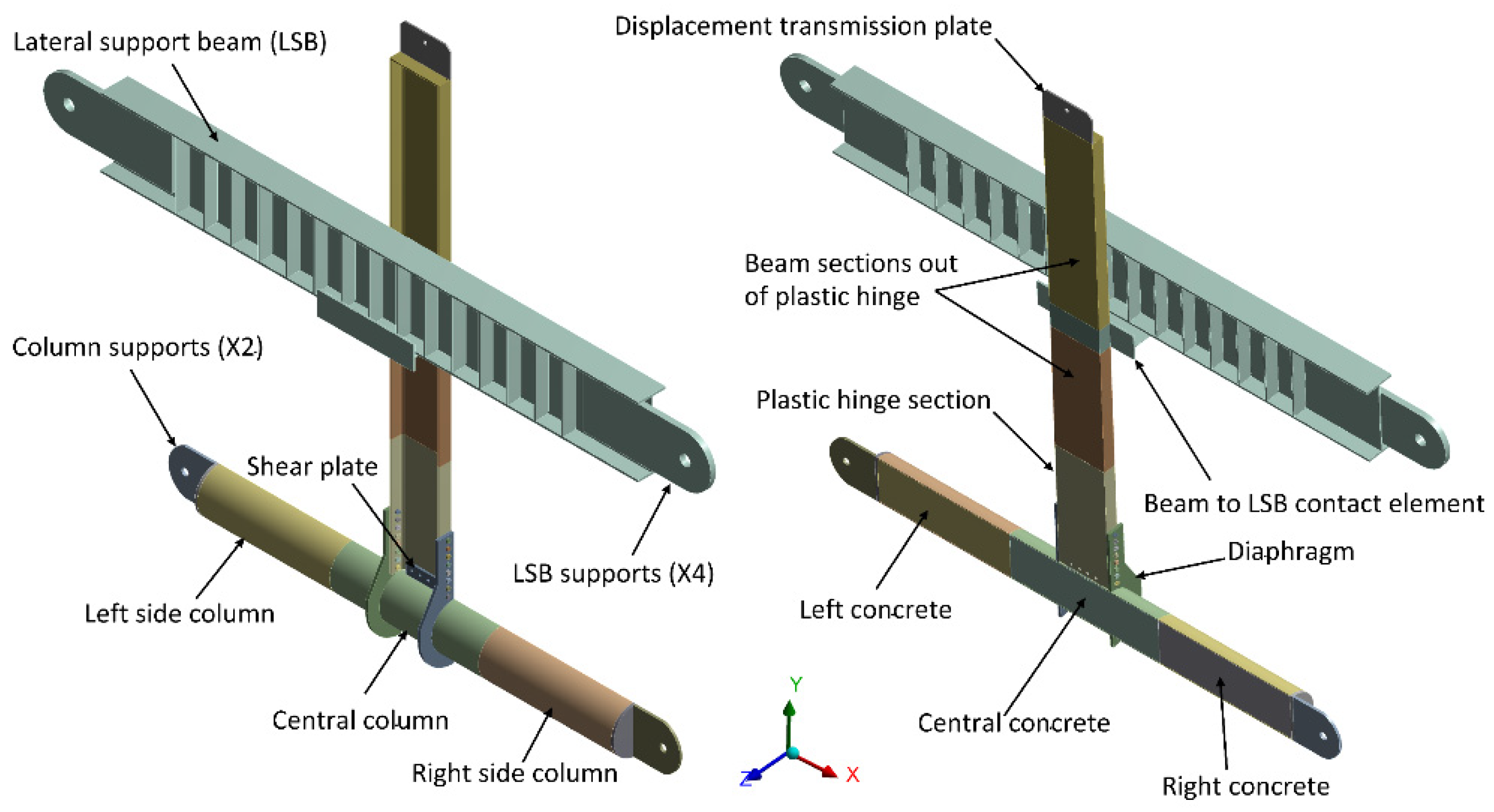
19]. In this context, we present a FEM-based model and its application to predict the seismic response and behavior of this connection. This is presented showing relevant aspects of the numerical model for the design of this type of connection in terms of its flexural capacity, plasticization mechanism and plastic hinging location. The analysis was conducted according to the criteria established by current regulations and the results of previous experimental tests. In addition, two stages of simplifications were conducted in the original model aimed at improving its suitability for engineering purposes.
4. Conclusions
The increase in the use of SMFs motivates the use of new connections that are not homologated under the current design regulations. Therefore, studies are required to ensure that the designed frames dissipate the seismic energy in the beams without affecting the connections. In this context, this work presents a numerical model and an analysis of the inelastic behavior under cyclic loads of a steel beam-to-concrete-filled steel tubular column connection using external diaphragms.
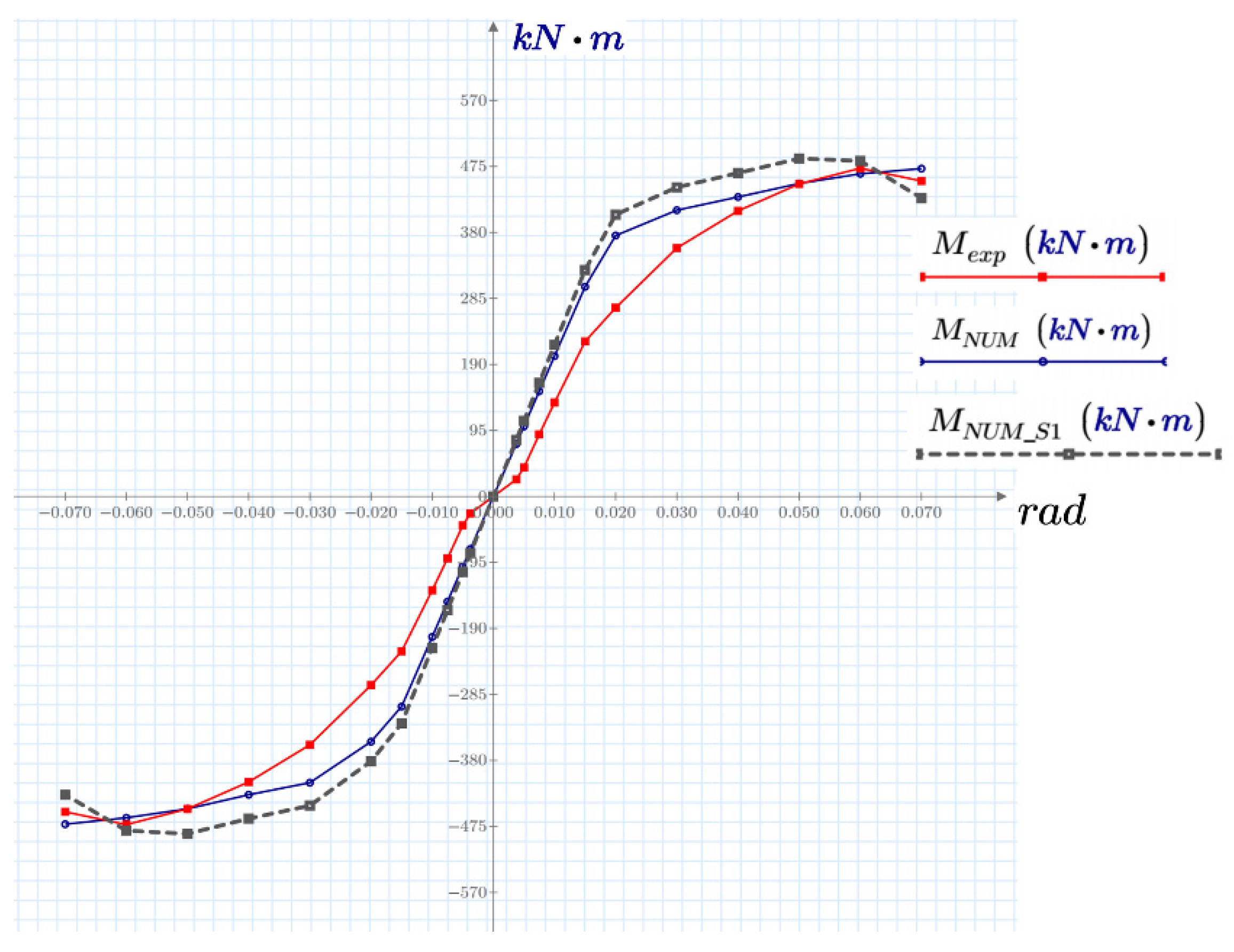
The model was based on the FEM and built in Ansys, and showed satisfactory results when compared with experiments. In addition, two stages of simplification were conducted to reduce the computational time required for the calculations.
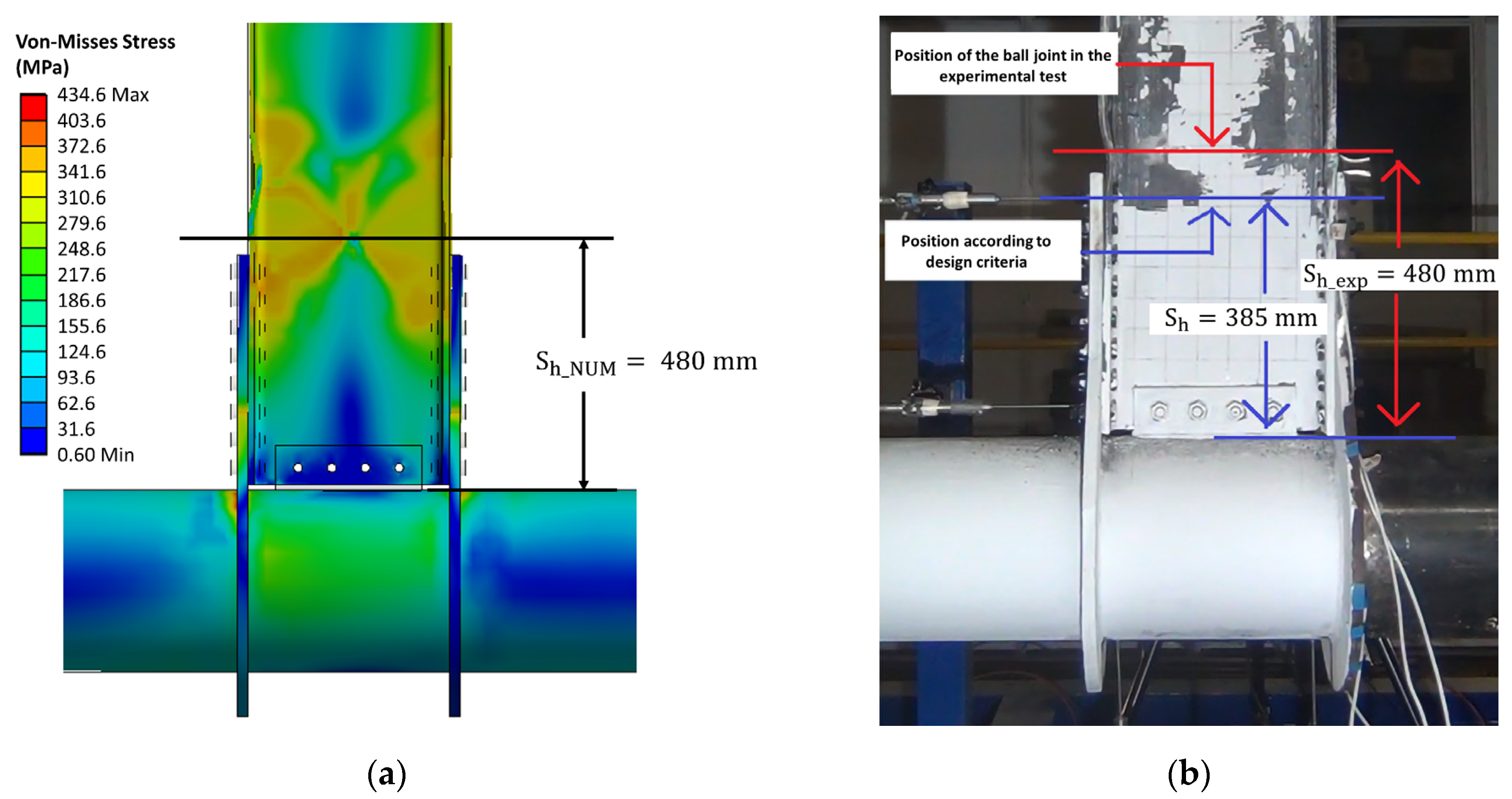
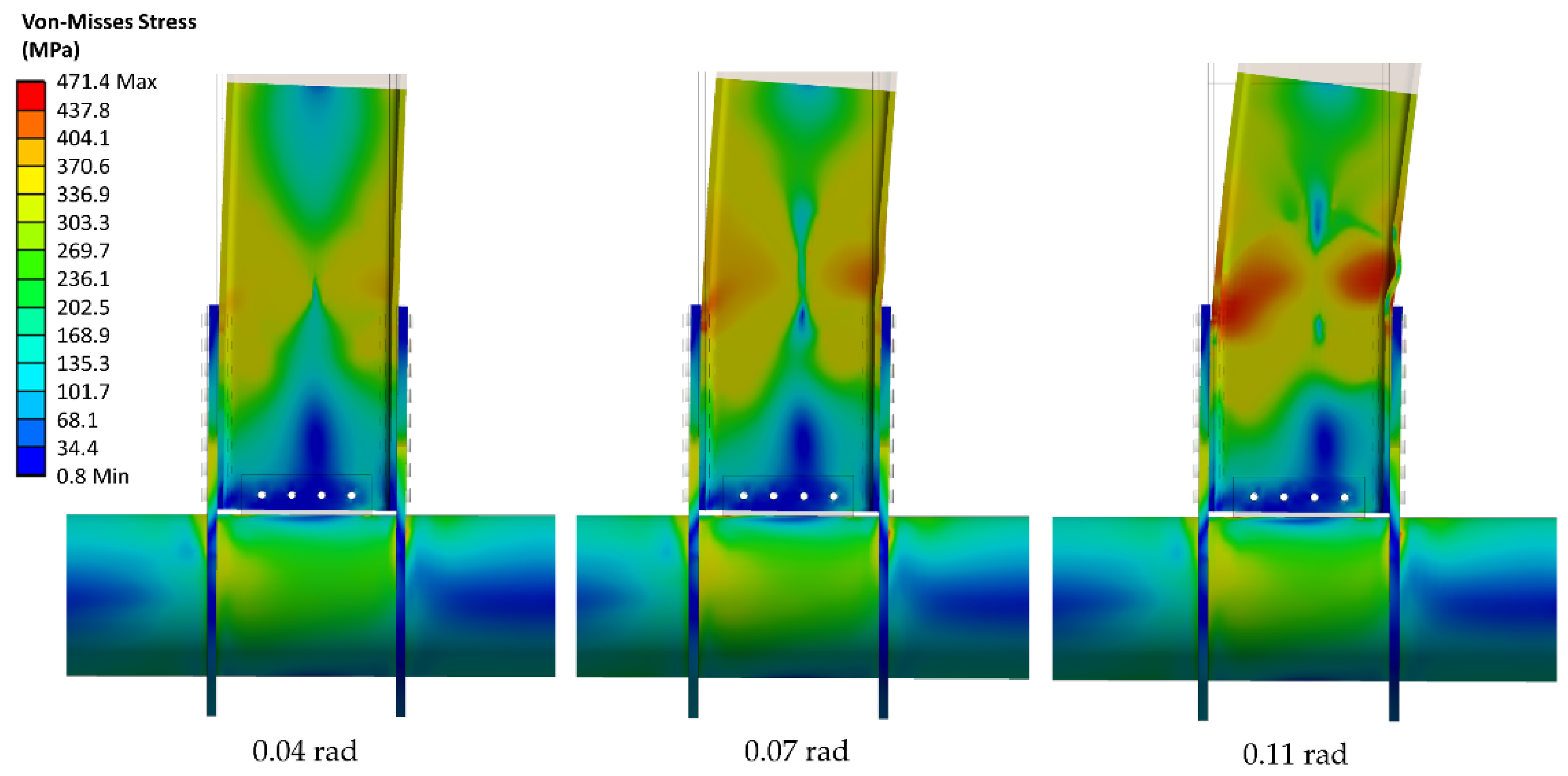
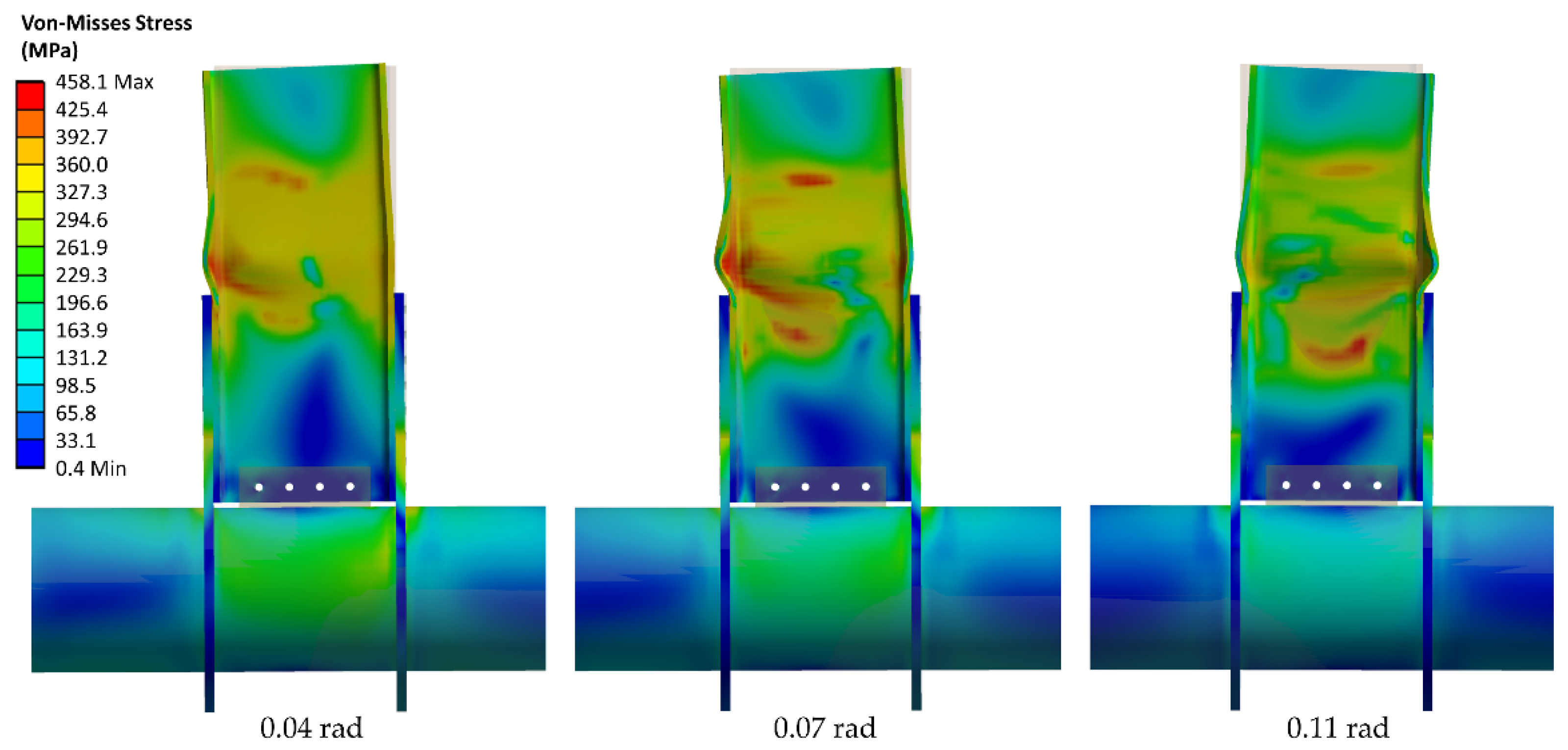
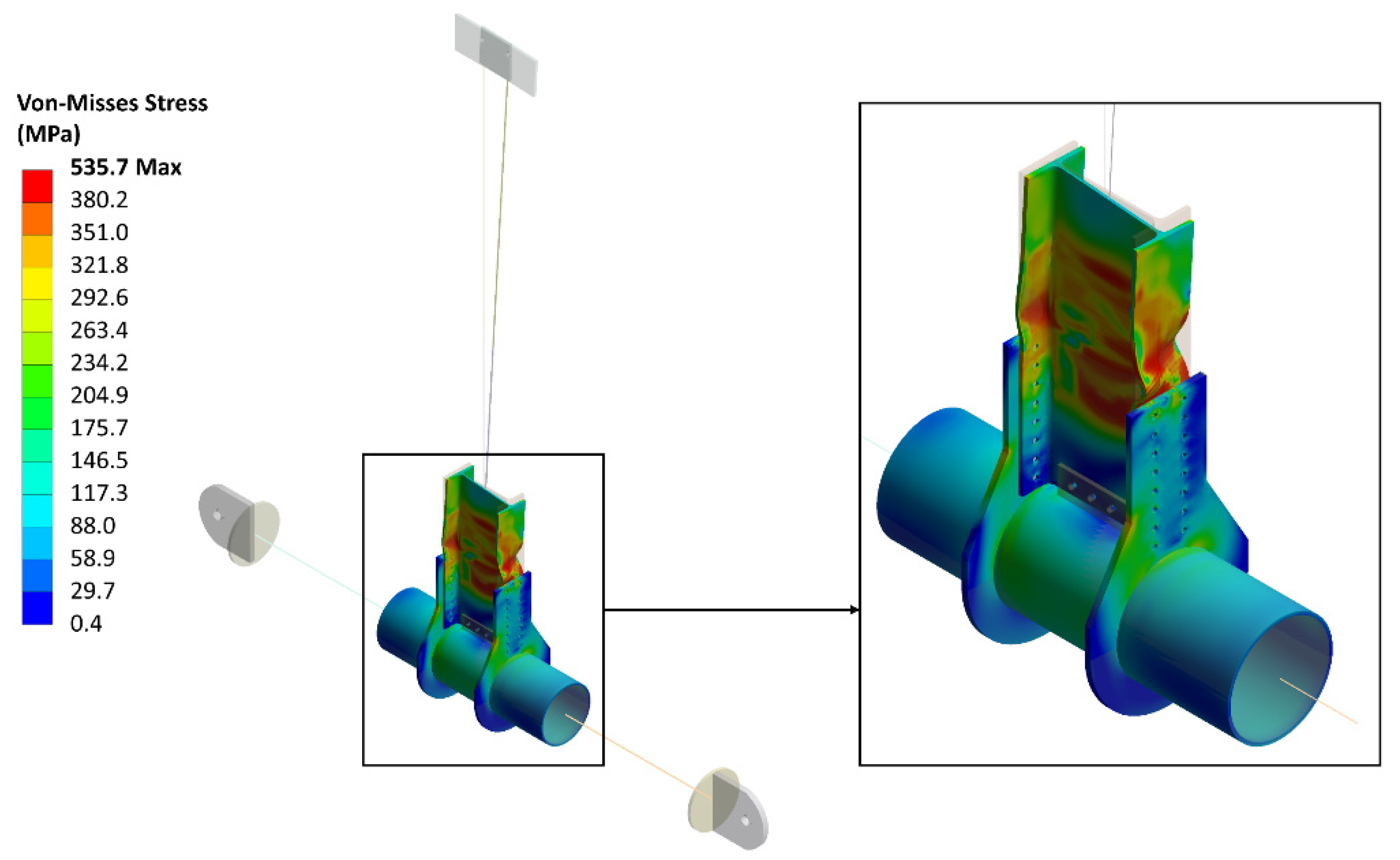
Although the nonlinear effect of the connection considered in the model included the effect of large deformations and the kinematic hardening of the material, the pinching effect due to bolt slip was not included. Nonetheless, the nonlinearity caused by this effect was accounted for in a practical way by a fitting coefficient. This approach led to good agreement with the experimental results in the nonlinear range. In addition, the nonlinear effect of the connection was captured with good results in terms of the location of the plastic hinging and the plasticization mechanism.
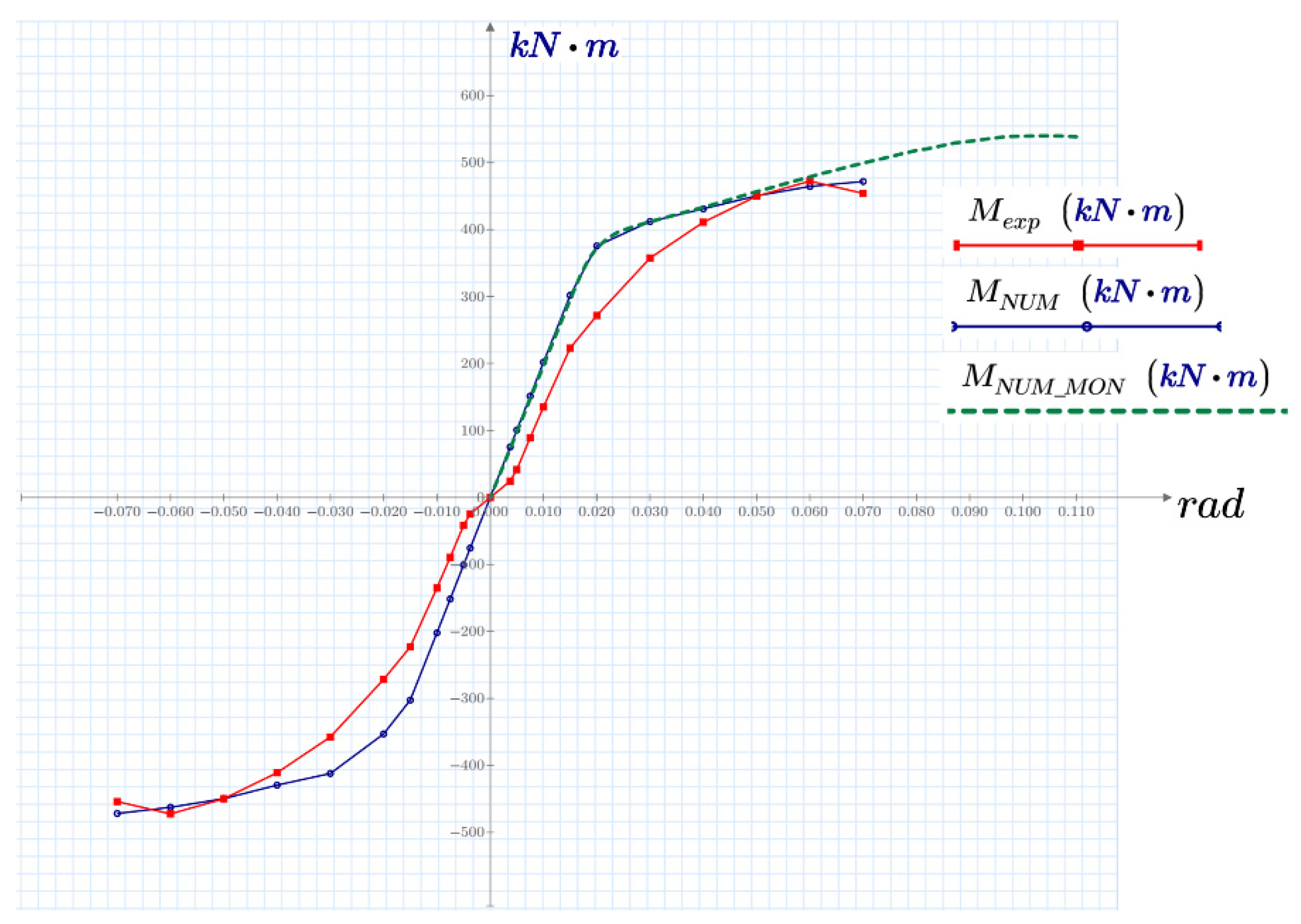
It was also observed that the approximate envelope of the hysteretic curves provided by the monotonic test was verified as stated by FEMA 355D [
13]. Moreover, a good correlation was observed, especially between the angular rotation from 0.04 to 0.07 rad, where the agreement was within 1%. In addition, the monotonic analysis provided a good estimate for the plasticization mechanism and the location of the plastic hinge. This was also the case after the model simplifications conducted in the first and second stages.
Regarding the reductions in the computational time, it was observed that the use of the monotonic test instead of cyclic loading decreased the time spent to reach a solution by 21 times. The first- and second-stage simplifications decreased the computational time 56-fold with respect to the original model. Finally, if the monotonic test is used along with the simplifications conducted in the first and second stages, the time reduction is 84-fold.
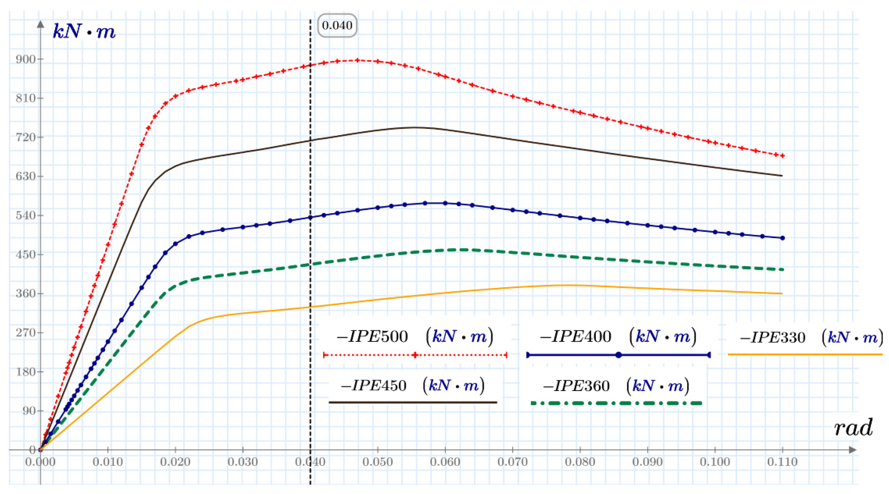
A parametric study was carried out with the numerical model including all the simplifications. In this study, four European type I profiles were analyzed using the monotonic test and the two model simplification stages. To select these profiles, the possible steel sections with the greatest possibility of meeting drifts or lateral displacement in frames with special energy dissipation capacity for medium- and low-rise buildings were considered. The results show that for all the configurations, the resistance moment was greater than the limit that must be reached to determine its applicability in special energy dissipation systems. Thus, all the connections satisfy the qualification requirements of AISC 358 to be used in SMFs with special energy dissipation capacity. In addition, the plastic hinging location is out of the diaphragm zone.
Subsequent studies can be oriented to increase the portfolio of the steel beam-to-concrete-filled steel tubular column connection using external diaphragms by analyzing different configurations, i.e., column sections, beam profiles, and different type of concretes suitable for seismic resistant applications. In future research, the pinching effect can be also studied in more detail. In addition, in this work, the diaphragms were connected to the column wall by using full penetration welds with 45-degree bevels. Nonetheless, it would be worth considering the effect of combining full penetration and partial penetration welds. This, since the use of partial penetration welds would considerably reduce the manufacturing time and associated costs.


