
Improved Analytical Solution for Air–Boosted Vacuum Consolidation of Saturated Soil Using Eigenfunction Expansion Method


Abstract
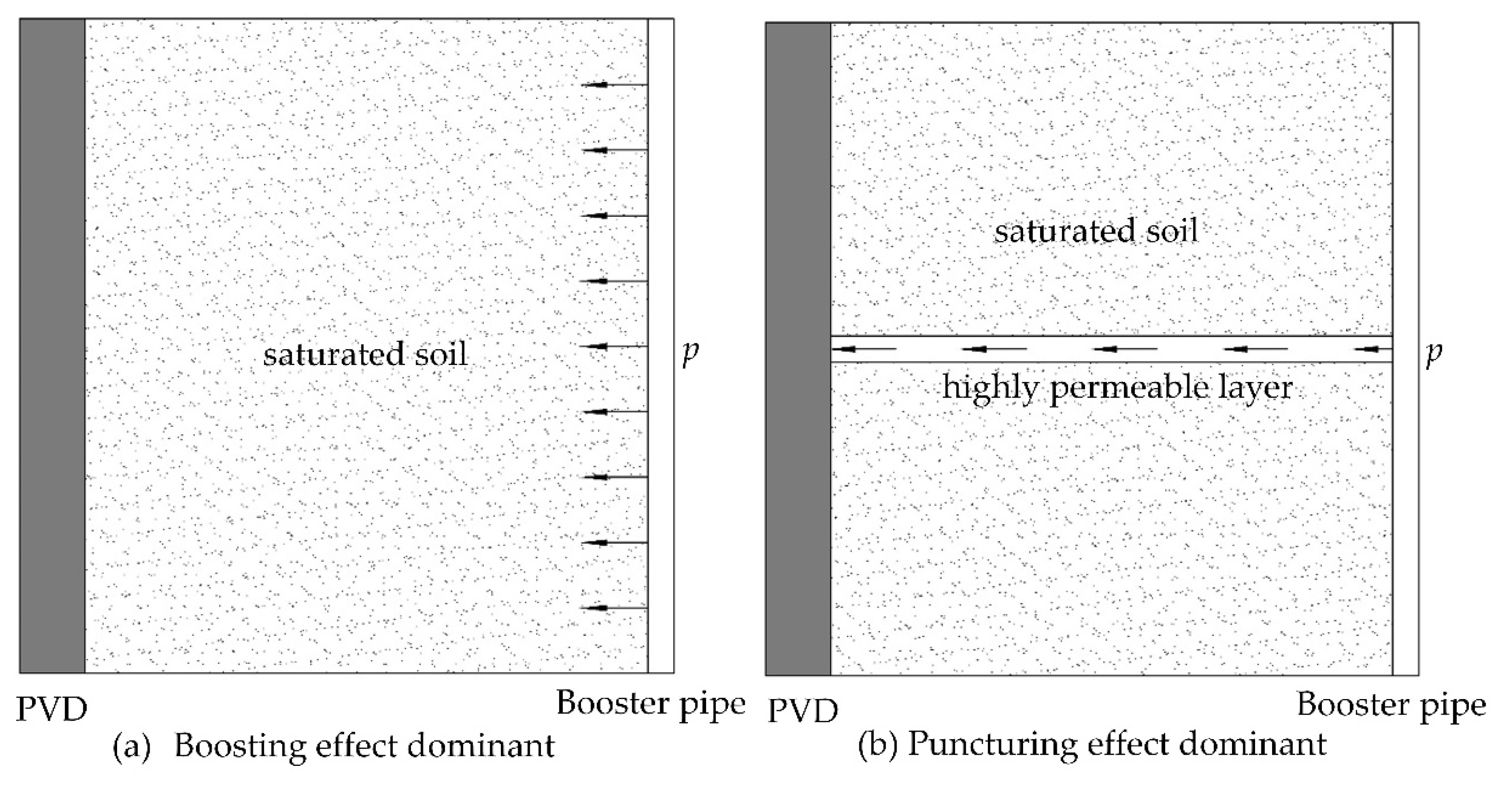
:1. Introduction
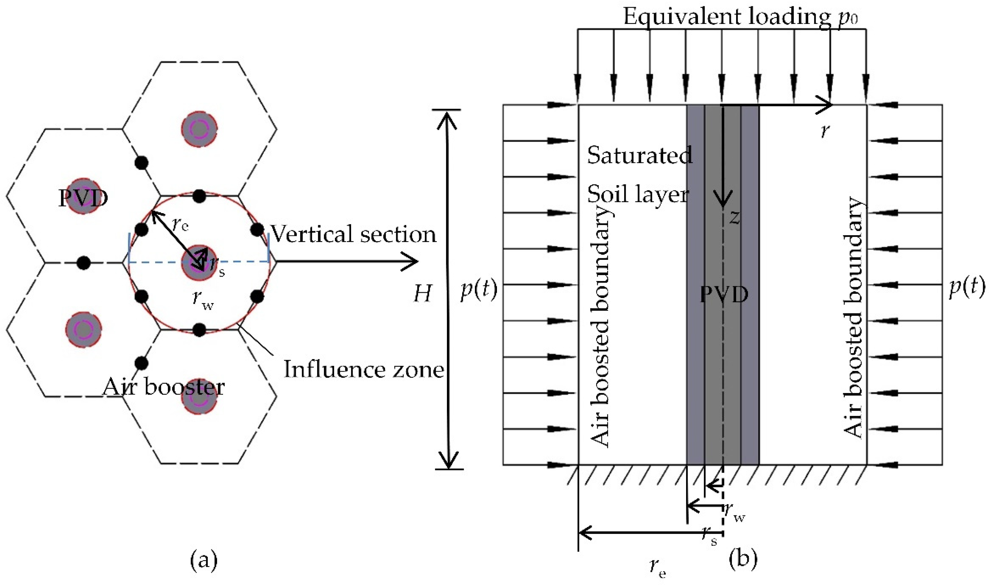
2. Mathematical Modeling
2.1. Governing Equations
2.2. Definite Conditions
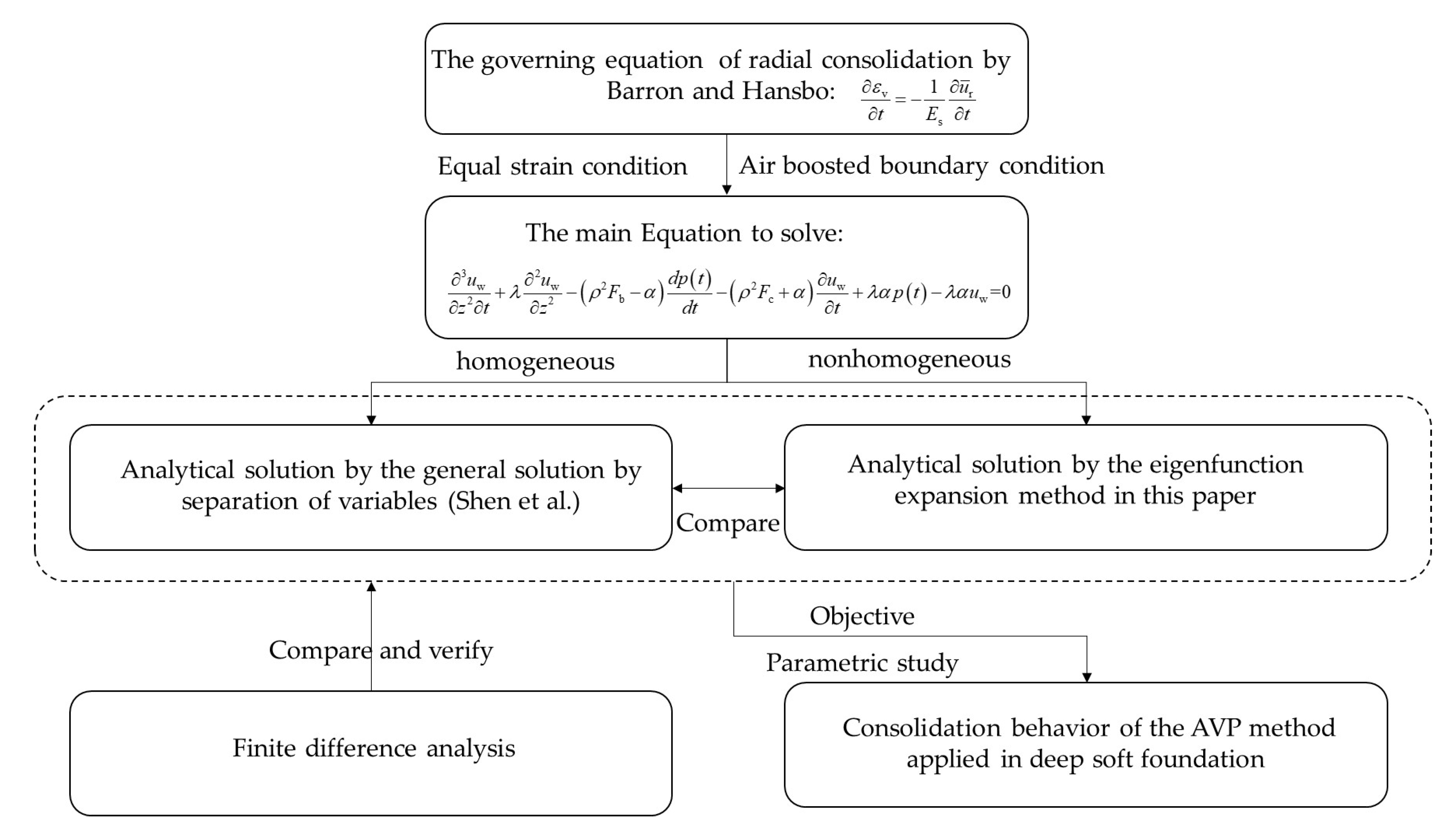
3. Solutions
3.1. The Analytical Solution of Shen et al.
3.2. Improved Analytical Solution by Eigenfunction Expansion Method
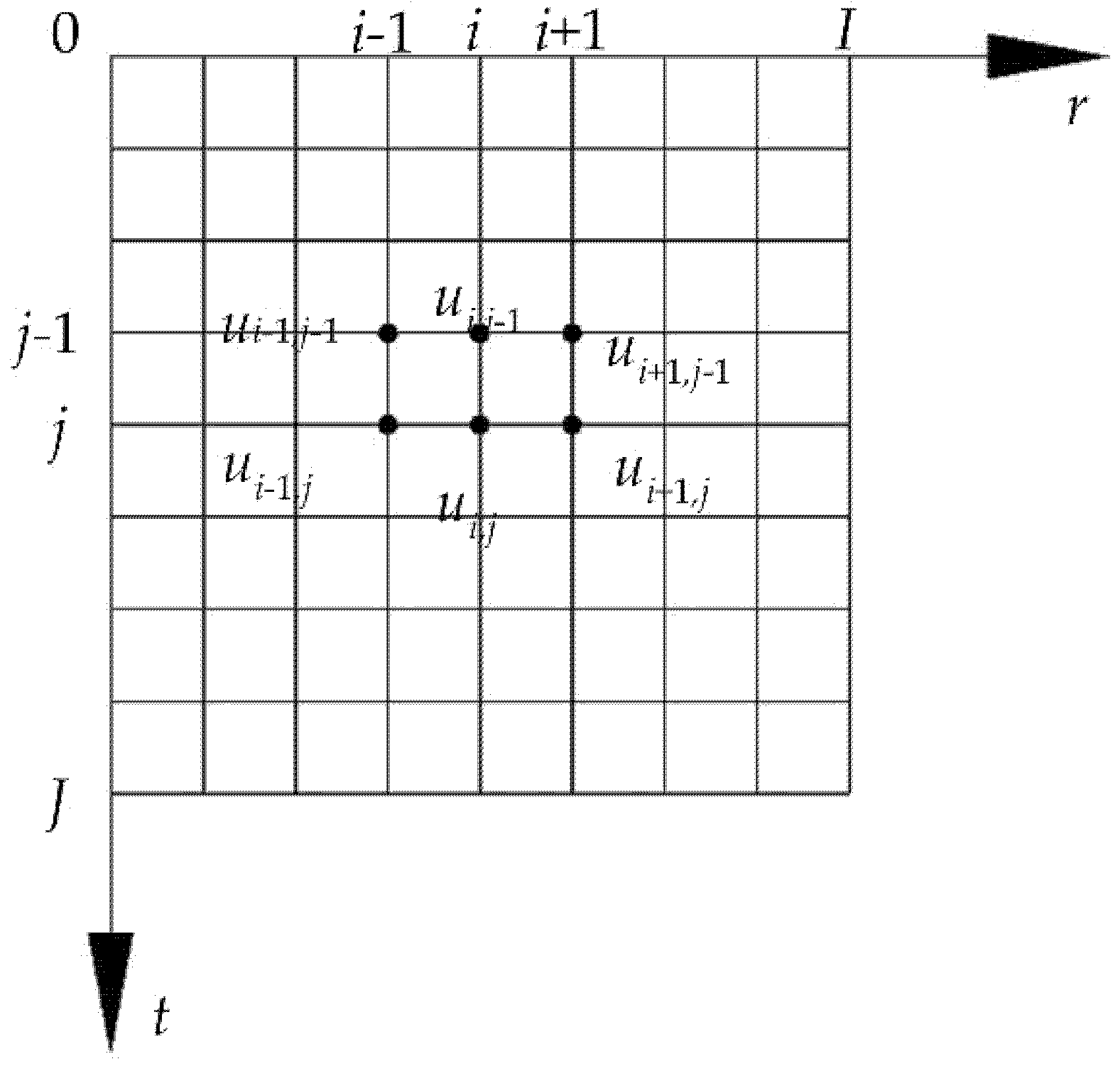
3.3. Finite Difference Analysis
4. Solution Verification
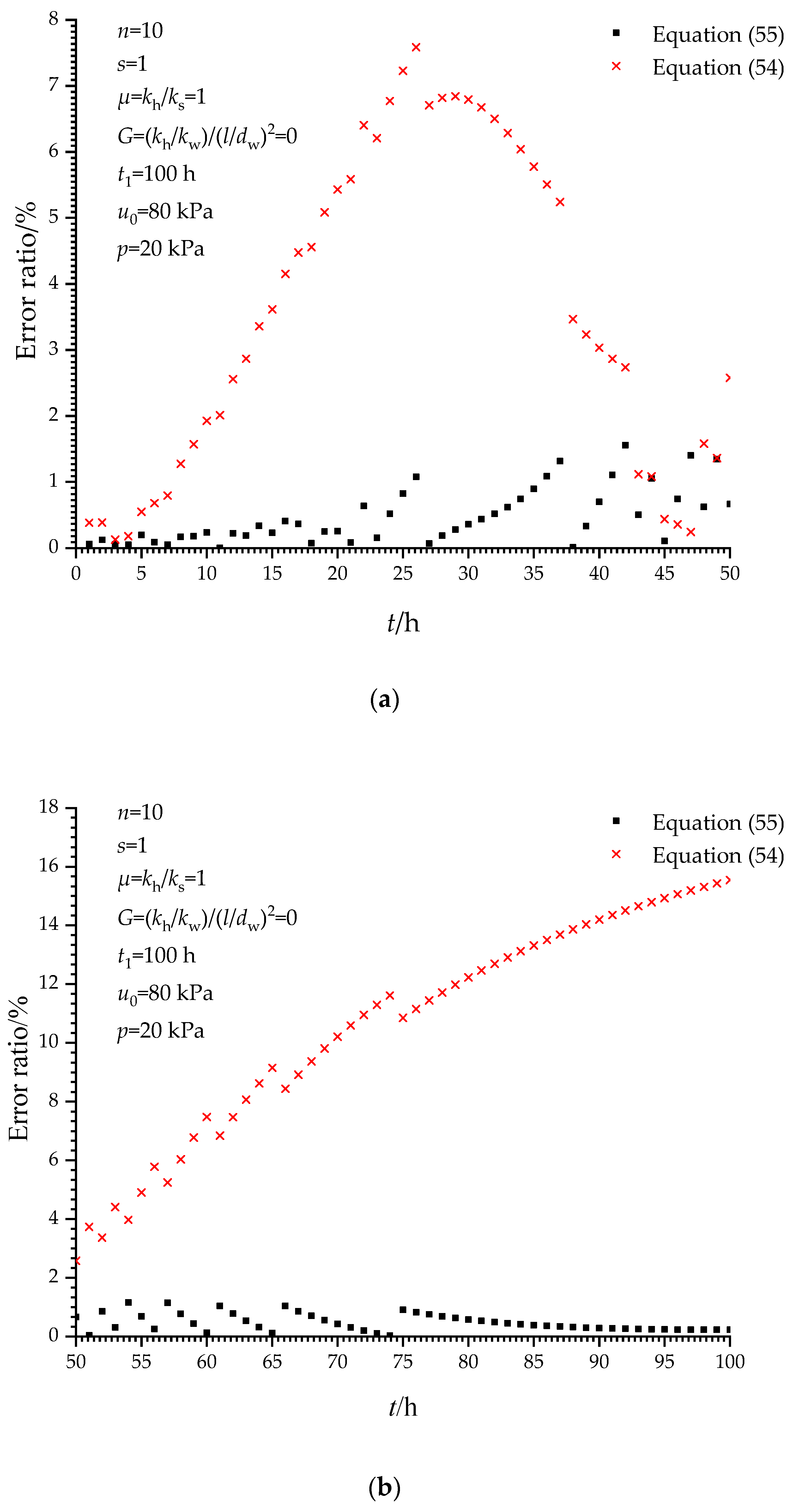
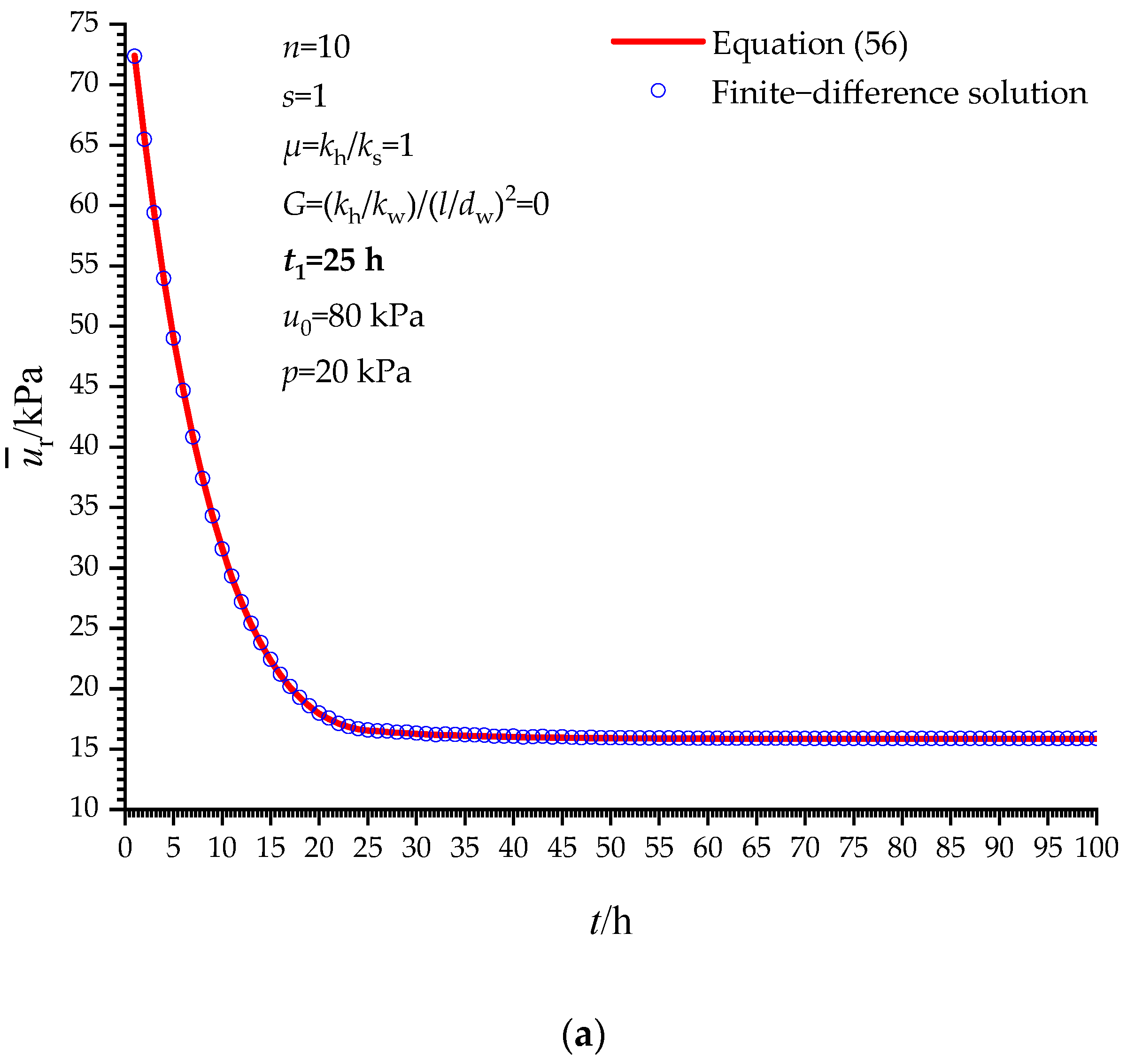
4.1. Verification When t ≤ t1
4.2. Verification When t > t1
5. Parametric Study
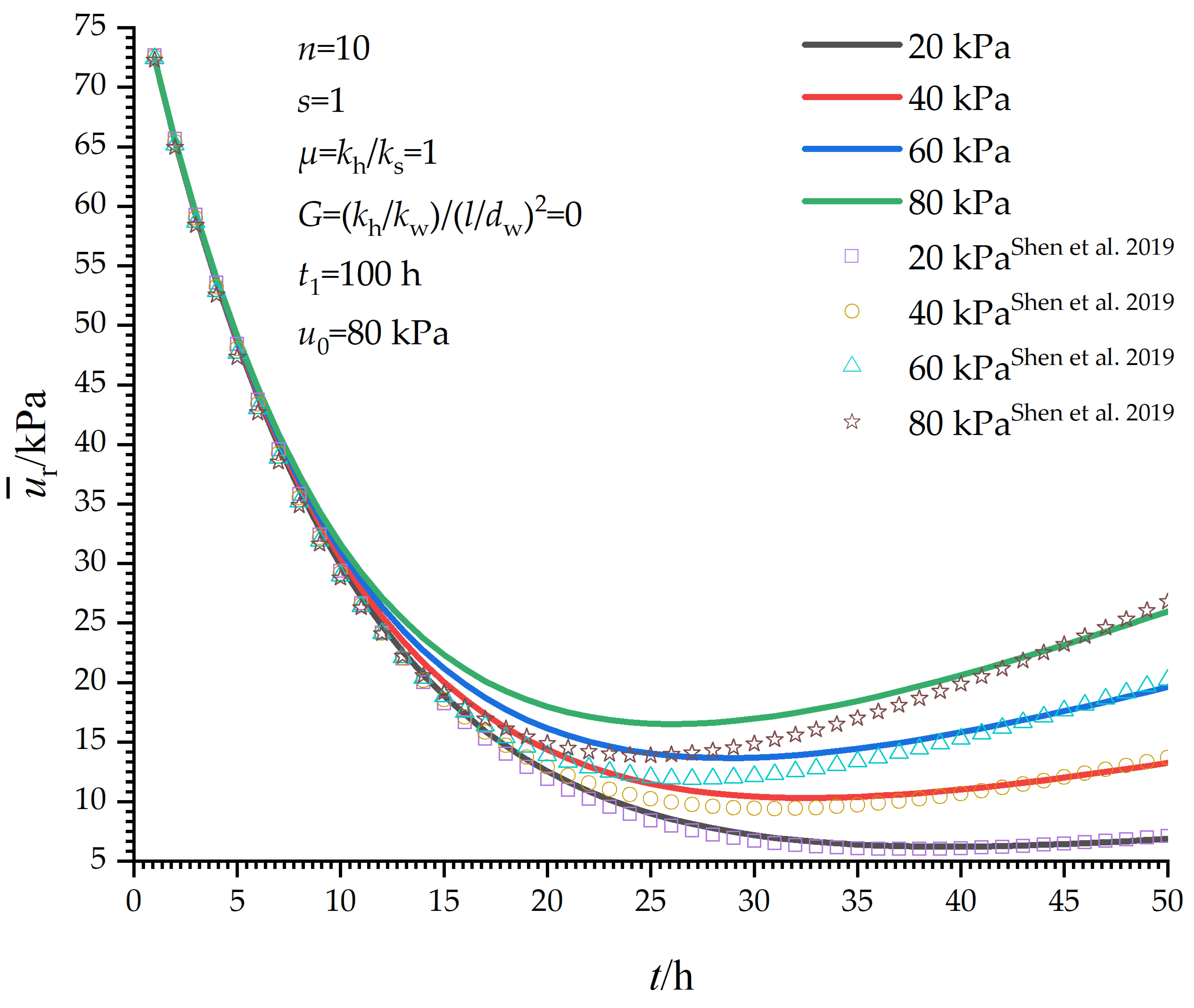
5.1. Influence of p
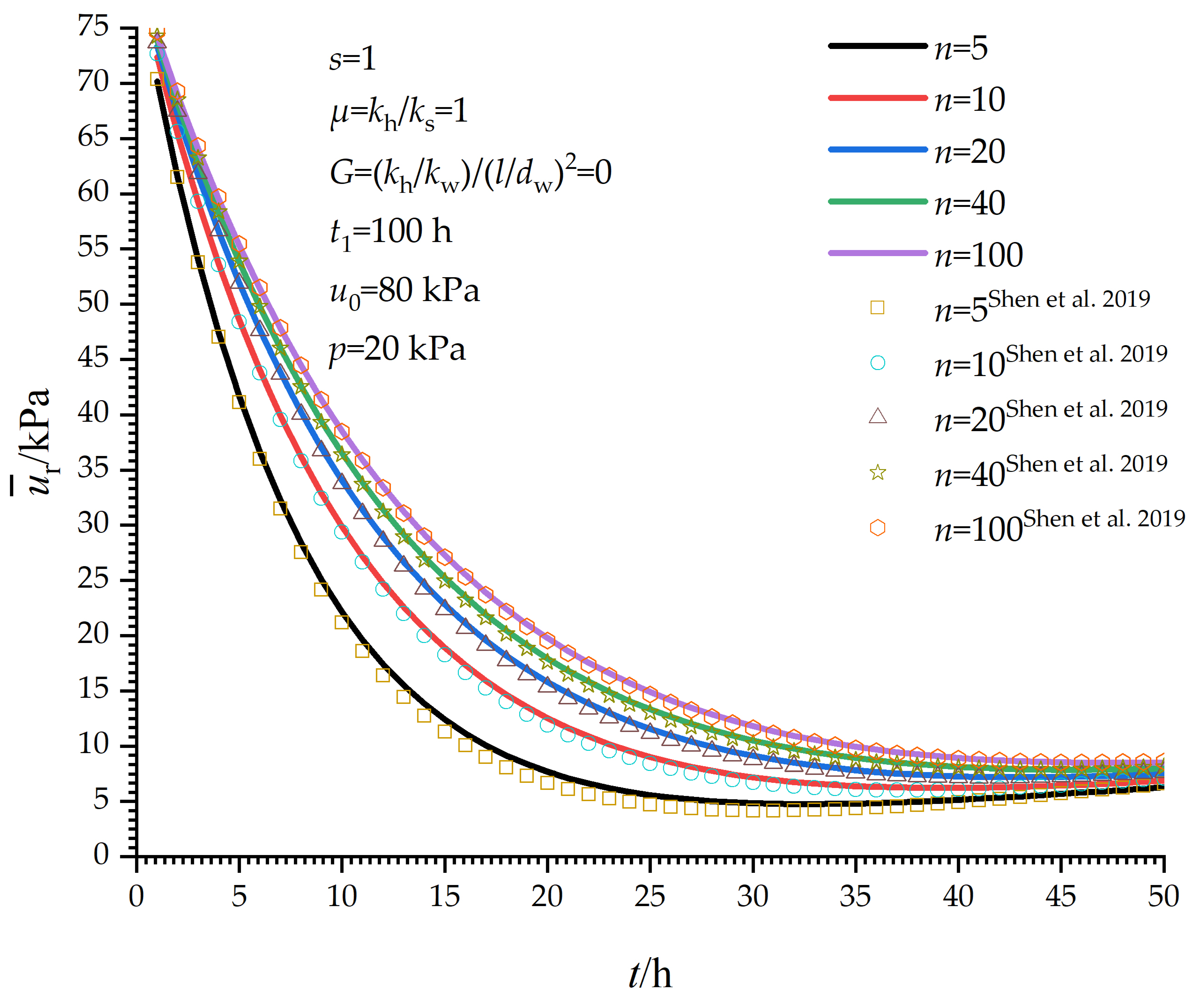
5.2. Influence of n
6. Discussion
7. Conclusions
Author Contributions
Funding
Institutional Review Board Statement
Informed Consent Statement
Data Availability Statement
Acknowledgments
Conflicts of Interest
Nomenclature
| ur | Excess pore water pressure in the radial direction |
| Average excess pore water pressure in the radial direction | |
| dw,ds,de | Diameter of the drain, the smear zone, and the model |
| rw,rs,re | The radius of the drain, the smear zone, and the model |
| Es | Oedometric modulus of the soil |
| G | The factor of well resistance |
| kw,kh,ks | The permeability coefficient of the drain, the smear zone, and the undisturbed zone |
| n | The ratio of influence radius to vertical drain radius |
| s | The ratio of smear zone to vertical drain radius |
| l | Depth of the soil |
| p0 | Equivalent uniform load of vacuum preloading |
| p(t) | The pressure of boosted air |
| t | Time |
| r | Radial coordinate |
References
- Prasanna, S.; Kumar, P. Soil Reinforcement Using Coconut Shell Ash: A Case Study of Indian Soil. J. Civ. Eng. Constr. 2017, 6, 73–78. [Google Scholar]
- Chai, J.C.; Carter, J.P.; Hayashi, S. Vacuum Consolidation and Its Combination with Embankment Loading. Can. Geotech. J. 2006, 43, 985–996. [Google Scholar] [CrossRef]
- Jin, Y.W.; Jin, Y.J.; Jiang, J.N.; Sun, Q.B.; Tang, X.W. Pressurized Vacuum Preloading Consolidation Method for Soft Soil Foundation/Tailing Slag/Lake Mud; China National Intellectual Property Administration: Beijing, China, 2011. [Google Scholar]
- Shen, Y.; Wang, H.; Tian, Y.; Feng, R.; Liu, J.; Wu, L. A New Approach to Improve Soft Ground in a Railway Station Applying Air–Boosted Vacuum Preloading. Geotech. Test. J. 2015, 38, 20140106. [Google Scholar] [CrossRef]
- Liu, S.; Zhang, D.; Du, G.; Han, W. A New Combined Vacuum Preloading with Pneumatic Fracturing Method for Soft Ground Improvement. Procedia Eng. 2016, 143, 454–461. [Google Scholar] [CrossRef]
- Tu, H.-Z.; Xu, Y.-H.; Xie, L.-Q. Mechanism and Numerical Analysis of Effect of Air Injection on Vacuum Preloading for Weak Foundation Improvement. Rock Soil Mech. 2014, 35, 600–606. [Google Scholar]
- Xie, L.Q.; Li, Y.; Liang, X. Field Test of the Mechanism of Increase and Dissipation of Pore Pressure of Air Injection on Vacuum Drainage for Soft Ground Improvement. Struct. Eng. 2019, 035, 243–251. [Google Scholar]
- Wang, J.; Cai, Y.; Ma, J.; Chu, J.; Fu, H.; Wang, P.; Jin, Y. Improved Vacuum Preloading Method for Consolidation of Dredged Clay–Slurry Fill. J. Geotech. Geoenviron. Eng. 2016, 142, 2–6. [Google Scholar] [CrossRef]
- Ding, H.; Guo, Z.; Fan, K.; Wang, Z.; Ming, Q. Comparative Experiment on Soft Soil Treatment by Air–Boosted Vacuum Preloading. Chin. J. Undergr. Space Eng. 2015, 11, 16. [Google Scholar]
- Hu, J.B.; Man, P.; Li, W.; Wang, W.G.; Peng, J. Field Tests on Marine Dredger Fill Foundation by Air–Boosted Vacuum Preloading. Sci. Technol. Eng. 2018, 18, 124–129. [Google Scholar]
- Cai, Y.; Xie, Z.; Wang, J.; Wang, P.; Geng, X. New Approach of Vacuum Preloading with Booster Prefabricated Vertical Drains (PVDs) to Improve Deep Marine Clay Strata. Can. Geotech. J. 2018, 55, 1359–1371. [Google Scholar] [CrossRef]
- Feng, S.X.; Lei, H.Y.; Ding, X.D.; Zheng, G.; Jin, Y.W. Shallow Ground Treatment by a Combined Air Booster and Straight–Line Vacuum Preloading Method: A Case Study. Geomech. Eng. 2021, 24, 129–141. [Google Scholar] [CrossRef]
- Feng, S.X.; Zhou, J.F. Field Instrumentation and Evaluation of Ground Treatment by Combined Air–Booster and Straight–Line Vacuum Preloading without Sand. Mar. Georesour. Geotechnol. 2022, 40, 267–280. [Google Scholar] [CrossRef]
- Lei, H.; Hu, Y.; Zheng, G.; Liu, J.; Wang, L.; Liu, Y. Improved Air–Booster Vacuum Preloading Method for Newly Dredged Fills: Laboratory Model Study. Mar. Georesour. Geotechnol. 2020, 38, 493–510. [Google Scholar] [CrossRef]
- Lei, H.; Fang, Q.; Liu, J.; Zheng, G.; Wang, P.; Gao, L. Ultra–Soft Ground Improvement Using Air–Booster Vacuum Preloading Method: Laboratory Model Test Study. Int. J. Geosynth. Ground Eng. 2021, 7, 87. [Google Scholar] [CrossRef]
- Lei, H.; Hu, Y.; Liu, J.; Liu, X.; Li, C. Consolidation Behavior of Tianjin Dredged Clay Using Two Air–Booster Vacuum Preloading Methods. J. Zhejiang Univ. A 2021, 22, 147–164. [Google Scholar] [CrossRef]
- Lei, H.Y.; Hu, Y.; Lei, S.H.; Qi, Z.Y.; Xu, Y.G. Analysis of microstructure characteristics of air–booster vacuum preloading for ultra–soft dredger fills. Rock Soil Mech. 2019, 40, 32–40. [Google Scholar] [CrossRef]
- Hu, X.Q.; Zhang, W.K.; Fu, H.T.; Wang, J.; Ni, J.F. Clogging Effect of Prefabricated Horizontal Drains in Dredged Soil by Air Booster Vacuum Consolidation. Geotext. Geomembr. 2021, 49, 1529–1538. [Google Scholar] [CrossRef]
- Ke, S.W.; Wang, P.; Hu, X.Q.; Geng, X.Y.; Hai, J.; Jin, J.Q.; Jiang, Z.W.; Ye, Q.; Chen, Z.J. Effect of the Pressurized Duration on Improving Dredged Slurry with Air Booster Vacuum Preloading. Mar. Georesour. Geotechnol. 2020, 38, 970–979. [Google Scholar] [CrossRef]
- Anda, R.; Fu, H.; Wang, J.; Lei, H.; Hu, X.; Ye, Q.; Cai, Y.; Xie, Z. Effects of Pressurizing Timing on Air Booster Vacuum Consolidation of Dredged Slurry. Geotext. Geomembr. 2020, 48, 491–503. [Google Scholar] [CrossRef]
- Xie, Z.; Wang, J.; Fu, H.; Cai, Y.; Xiuqing, H.; Cai, Y.; Zhang, Y.; Ma, X.; Jin, H. Effect of Pressurization Positions on the Consolidation of Dredged Slurry in Air–Booster Vacuum Preloading Method. Mar. Georesour. Geotechnol. 2020, 38, 122–131. [Google Scholar] [CrossRef]
- Shi, L.; Hu, D.; Cai, Y.; Pan, X.; Sun, H. Preliminary Study of Real–Time Pore Water Pressure Response and Reinforcement Mechanism of Air–Booster Vacuum Preloading Treated Dredged Slurry. Rock Soil Mech. 2020, 41, 185–193. [Google Scholar] [CrossRef]
- Lei, H.Y.; Wang, P.; Xu, L.; Lei, W. Influence of Gas Migration Patterns on Reinforcement of Dredged Slurry by Air–Booster Vacuum Preloading Method. Rock Soil Mech. 2021, 42, 943–953. [Google Scholar] [CrossRef]
- Xie, L.Q.; Niu, Y.C.; Liu, F.; Liu, S.G. Numerical Analysis of Vacuum Drainage with Air Injection. Chin. J. Undergr. Space Eng. 2009, 5, 1590–1593. [Google Scholar]
- Hu, Y.; Han, W.; Liu, S. Consolidation Analysis of Combined Method of Vacuum Preloading and Pneumatic Fracturing. J. Yangzhou Univ. Sci. Ed. 2016, 19, 58–63. [Google Scholar]
- Shen, Y.; Wang, Y.; Dong, S.; Jin, Y.; Wang, Y. Study on Consolidation Theory of Single–Layer Homogeneous Soil Treated by Air–Boosted Vacuum Preloading. J. China Railw. Soc. 2019, 41, 118–124. [Google Scholar] [CrossRef]
- Shen, Y.; Dong, S.; Wang, Y.; Jin, Y.; Li, X. Comparative Analysis between Integral–Transform Solution and Separate Variable Method for Consolidation of the Ground by Air–Boosted Vacuum Preloading. Chin. J. Rock Mech. Eng. 2019, 38, 3171–3178. [Google Scholar]
- Shen, Y.; Liu, Y.; Geng, S.; Qi, Y.; Dong, S.; Xin, X.; Sun, J.; Zheng, H. Consolidation Theory of Homogeneous Multilayer Treatment by Air–Boosted Vacuum Preloading. Eur. J. Environ. Civ. Eng. 2021, 1–19, Early Access. [Google Scholar] [CrossRef]
- Peng, W.; Gu, B.; Yang, H.; Yang, X.; Yu, Z. Analysis Method for Consolidation of Soil under Vacuum Preloading Assisted by Air Booster. Mar. Georesour. Geotechnol. 2021, 1–5, Early Access. [Google Scholar] [CrossRef]
- Barron, R.A. Consolidation of Fine–Grained Soil by Drain Wells. Trans. ASCE 1948, 113, 718–742. [Google Scholar]
- Hansbo, S. Consolidation of Fine–Grained Soils by Prefabricated Drains. Int. J. Rock Mech. Min. Sci. Geomech. Abstr. 1981, 3, 677–682. [Google Scholar] [CrossRef]
- Xie, K.H.; Zeng, G.X. Consolidation Theories for Drain Wells under Equal Strain Condition. Chin. J. Geotech. Eng. 1989, 11, 3–17. [Google Scholar]


Publisher’s Note: MDPI stays neutral with regard to jurisdictional claims in published maps and institutional affiliations. |
© 2022 by the authors. Licensee MDPI, Basel, Switzerland. This article is an open access article distributed under the terms and conditions of the Creative Commons Attribution (CC BY) license (https://creativecommons.org/licenses/by/4.0/).
Share and Cite
Xie, L.; Liang, Z.; Feng, G.; Li, Y.; Wu, T. Improved Analytical Solution for Air–Boosted Vacuum Consolidation of Saturated Soil Using Eigenfunction Expansion Method. Symmetry 2022, 14, 1757. https://doi.org/10.3390/sym14091757
Xie L, Liang Z, Feng G, Li Y, Wu T. Improved Analytical Solution for Air–Boosted Vacuum Consolidation of Saturated Soil Using Eigenfunction Expansion Method. Symmetry. 2022; 14(9):1757. https://doi.org/10.3390/sym14091757
Chicago/Turabian StyleXie, Liquan, Zelong Liang, Guangrui Feng, Yanhong Li, and Tongqing Wu. 2022. "Improved Analytical Solution for Air–Boosted Vacuum Consolidation of Saturated Soil Using Eigenfunction Expansion Method" Symmetry 14, no. 9: 1757. https://doi.org/10.3390/sym14091757