Review

Echelle Grating Spectroscopic Technology for High-Resolution and Broadband Spectral Measurement

1
Key Laboratory of Opto-Electronics Information Technology, Ministry of Education, Tianjin University, Tianjin 300072, China
2
Science and Technology on Electro-Optical Information Security Control Laboratory, Tianjin 300308, China
3
State Key Laboratory of Precision Measurement Technology and Instruments, Tsinghua University, Beijing 100084, China
*
Authors to whom correspondence should be addressed.
Appl. Sci. 2022, 12(21), 11042; https://doi.org/10.3390/app122111042
Submission received: 31 August 2022 / Revised: 18 October 2022 / Accepted: 20 October 2022 / Published: 31 October 2022

Abstract

:
Echelle grating provides high spectral resolving power and diffraction efficiency in a broadband wavelength range by the Littrow mode. The spectrometer with the cross-dispersed echelle scheme has seen remarkable growth in recent decades. Rather than the conventional approach with common blazed grating, the cross-dispersed echelle scheme achieves the two-dimensional spatial distribution of the spectrum by one exposure without scanning in the broadband spectral range. It is the fastest and most sensitive spectroscopic technology as of now, and it has been extensively applied in commercial and astronomical spectrometers. In this review, we first highlight the characteristics of the echelle and then present the optical layout, detection approach, and method of calibration. Finally, we discuss the state-of-the-art implementations and applications of commercial and astronomical instruments.

1. Introduction

A spectrometric instrument is to separate incoming light into its various frequency components whose strength and value provide information about either the source or the intervening medium [1]. For many years, it has been important in the study of physics, and it is now equally important in astronomical, biological, chemical, metallurgical, and other analytical investigations [2,3,4,5,6]. In chemistry, toxicology, and forensic science, spectroscopy is used to determine the presence and concentration of chemical species in samples. In astrophysics, it provides clues as to the composition and processes in stars and planetary atmospheres, as well as clues as to the large-scale motions of objects in the universe. In telecommunications, spectrometers are being used to analyze the channels of fiber-optic networks. The spectroscopy mainly depends on dispersion, diffraction, inelastic scattering, or optical modulation. No matter which method is used, the spectral resolution and time resolution are of considerable importance for spectroscopic instruments. Capturing high-resolution transient spectra over a wide spectral range is a challenge for accurate and efficient spectral analysis. Prism dispersion is short in terms of resolving power. A conventional grating cannot provide a uniform efficiency within a broad wavelength range. Raman spectrometers and Fourier transform spectrometers are limited in terms of time resolution and wavelength coverage. For high-resolution transient spectral analysis, an echelle spectrometer is the best choice.
The echelle is a kind of grating whose property is between the echelette and the echelon. It is coarsely ruled with large blaze angles and low groove frequencies, and it is used in high diffraction orders, so the grating period is greater than the wavelength of interest. Typical echelle groove spacings are 31.6, 79, and 316 g/mm, and blaze angles are 63.4°, 76°, 80.5°, and 82.8°, which correspond to R2, R4, R6, and R8 echelles. The characteristics of it were first described by George R. Harrison in 1949 [7,8,9,10,11,12]. The echelles were first applied in astronomy, both satellite- and ground-based, with specially designed instruments. Although there was some early analytical interest, it was not until the 1970s that instrumentation based on the echelle became generally available to analytical chemists [13]. This availability was due to the commercial acceptance and the astronomical applications. The dispersive system using an echelle can select the wavelength quickly and easily. Different from traditional gratings, echelles are used at large angles of incidence and diffraction with high diffraction orders, blaze in a full spectrum, and form a two-dimensional spectrum by a cross-dispersion scheme. It greatly increases the resolving power and intrinsic dispersion with a broad spectral coverage at fairly uniform efficiencies and increases the speed and compactness of spectrometers by the availability of shorter focal lengths, cyclic spectra, and the narrower geometry provided by the nearly identical exit angles of all wavelengths [10]. In higher orders, at least, the echelles are nearly free of polarization effects.
The echelle and cross-dispersion spectroscopic scheme is used by many high-end analytical instruments, including ICP-OES [14,15,16,17,18], AAS [19,20], and LIBS [21,22,23]. The spectral resolution is up to the picometer scale, and the wavelength covers the range from deep ultraviolet to near-infrared light. Due to the transient imaging and the high resolution at compact sizes, astronomical spectrometers also favor the echelle approach. Spectral analysis of the weak light collected by telescopes requires long-time exposure, and the echelle spectrometer can capture broadband spectra at one shot instead of scanning by ordinary blazed grating spectrometers [24]. It is very important for the analysis of the moving celestial body to seize the instantaneous state of the measured object [6].
In this review, we present the specific theoretical underpinnings of the echelle’s fundamental characteristics and illustrate typical optical layouts, detecting schemes and spectral calibration methods. We also describe the development and the state-of-the-art of commercial instruments and astronomical spectrometers. Finally, we discuss the future direction of this evolving field.

2. Fundamental Characteristics

2.1. High Resolving Power

An echelle is a kind of blazed grating, and the grating equation is:
sin i + sin θ = m λ / d
where i is the incidence angle, θ is the diffraction angle, λ is the wavelength, d is the groove spacing, and m is the diffraction order.
At a certain wavelength, when i and θ satisfy the following condition, the light at this wavelength is blazed, and the diffraction efficiency is maximum.
i + θ = 2 θ B
where θB is the blaze angle of the grating. The angular dispersion can be obtained from the grating equation:
d θ d λ = m d cos θ = sin i + sin θ λ cos θ
and the theoretical resolving power:
R = λ δ λ = m N = W λ ( sin i + sin θ )
where N is the total number of grooves illuminated on the grating surface, and W is the illuminated width of the grating. Equation (3) shows that the angular dispersion is only relevant to the incidence angle i and the diffraction angle θ. The larger i and θ are, the higher the angular dispersion is. Equation (4) shows that the resolving power also increases with the increase in i and θ. Replacing θ in Equation (4) with Equation (2), the resolving power at the blazed wavelength λb is expressed as:
R b = λ b δ λ b = W λ b ( sin i + sin ( 2 θ B i ) )
In differentiating Equation (5), we obtain the condition of the maximal resolution at the blazed wavelength:
d R b d i = W λ b ( cos i cos ( 2 θ B i ) ) = 0
When i = θB, the resolving power at the blazed wavelength is maximum. This type of layout is called the Littrow mode [25,26]. At this time, the angular dispersion is:
d θ d λ = 2 tan θ B λ
and the resolving power is:
R = λ δ λ = 2 W λ sin θ B
Equations (7) and (8) show that the angular dispersion and the resolving power at the blazed wavelength directly depend on the blaze angle of grating, which is normally 50–80° in an echelle. Assume that there is an echelle with a groove spacing of 79 gr/mm and a blaze angle of 76°. There is a common grating with a groove spacing of 1200 gr/mm and a blaze angle of 22°. The illuminated width of both gratings is 50 mm. Under the condition of λ = 632.8 nm, the resolution of the common grating is ~60,000, and the resolution of the echelle is ~155,000. So, the echelles have a higher intrinsic resolving power than that of common blazed gratings.

2.2. Blaze in Full Spectrum

By normalizing the diffraction intensity function of the echelle, the diffraction efficiency function can be expressed as:
I ˙ ( i , θ ) = I N 2 I 0 = ( sin δ b δ b ) 2 ( sin N δ d 2 N sin δ d 2 ) 2 = B F · ( I F / N 2 ) δ b = π λ b ( sin ( i θ B ) + sin ( θ θ B ) ) δ d = π λ d ( sin i + sin θ )
where BF is the blaze function, and IF is the interference function. When the rays of λb are just blazed, the grating equation is:
m λ b = d ( sin i + sin θ b )
θb is the diffraction angle of the rays of λb.
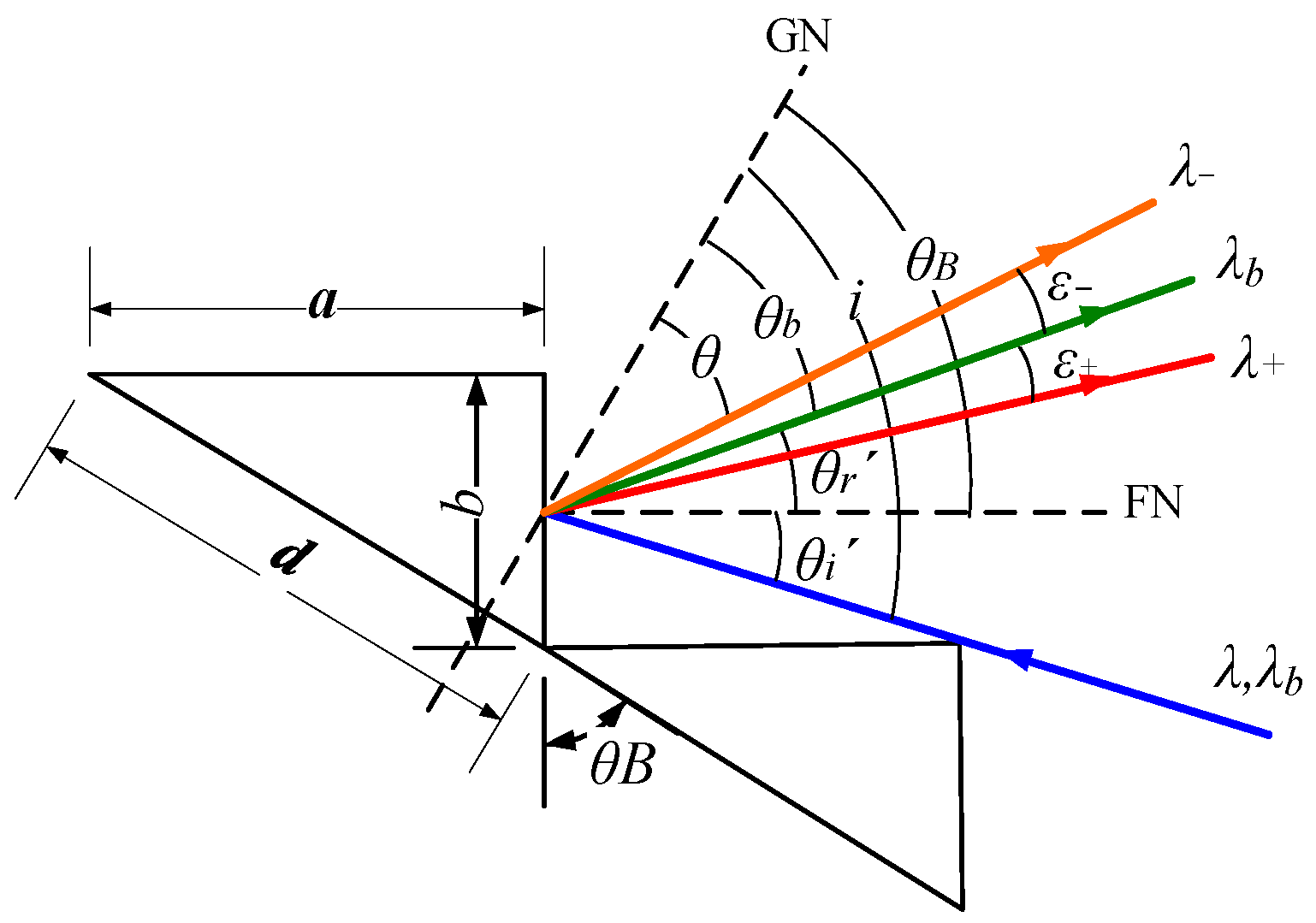
Let us investigate the diffraction of the wavelengths adjacent to the blaze wavelength. We assumed that λ+ and λ are slightly larger and smaller than λb, respectively, as shown in Figure 1.
Their corresponding grating equations are:
m λ ± = d ( sin i + sin ( θ b ± θ ε ± ) ) = m λ b d sin θ b ( 1 cos θ ε ± ) ± d cos θ b sin θ ε ±
Obviously, the diffraction efficiencies corresponding to different λ± vary. If we choose a pair of λ± where the BF value is 0.405, θε+ + θε = λ/(dcosθB). When θε± is very small, θε± is approximately:
θ ε ± = λ ± 2 d cos θ B
Thus, cosθε± is nearly equal to 1. When θb = θB, λ± can be described as:
λ ± = m λ b m 1 2
When m is large enough, there is:
λ + λ = m λ b m 2 1 / 4 = λ b m
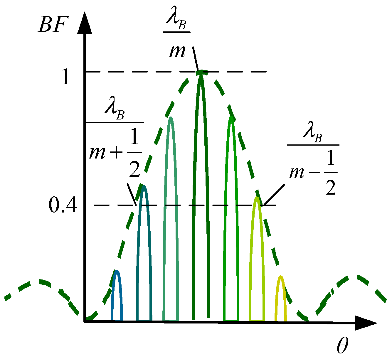
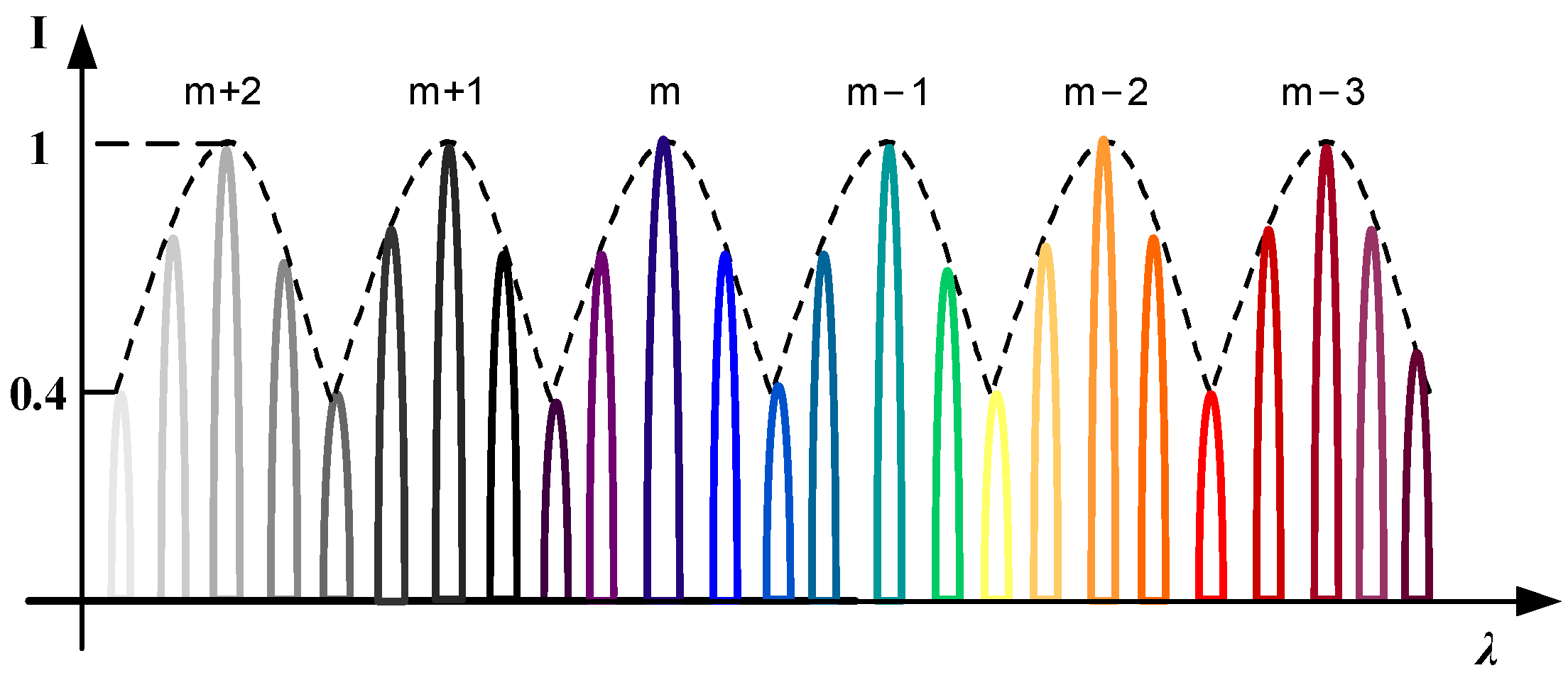
λb/m is exactly the free spectral range of the m-th order. It shows that the diffraction efficiency within the free spectral range is not lower than 40% (Figure 2).
Next, we discuss the relationship between the blazed wavelength of different orders and the free spectral range. It is assumed that the blazed wavelength of the first order at the Littrow mode is λB, and the blazed wavelength of the m-th order is λbm. Because the diffraction directions of these two wavelengths are the same, they can be depicted as:
λ B = 2 d sin θ B
λ b m = 1 m 2 d sin θ B = λ B m
From Equation (13), we can find that the upper limit of the free spectral range of the m-th order is just the lower limit of the free spectral range of the (m + 1)-th order:
λ B m + 1 / 2 = λ B ( m + 1 ) 1 / 2
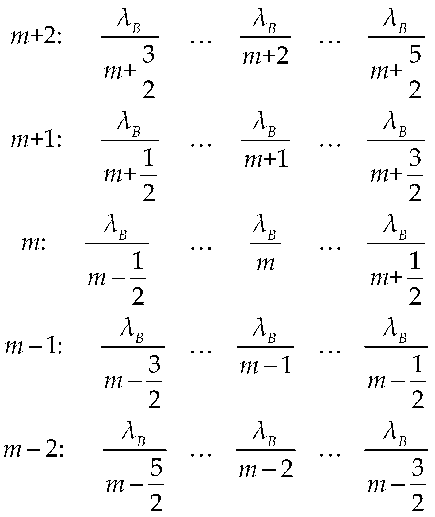
The free spectral range is very narrow, and the rays from different diffraction orders overlap with each other. The wavelength distribution at each order is shown in Figure 3.
The free spectral ranges of adjacent orders can be connected to form an entire broadband spectrum. The diffraction efficiency of all the wavelengths is higher than 40% (Figure 4), which is the characteristic of the blaze in the full spectrum.

3. Optical Layout

3.1. Littrow Mode

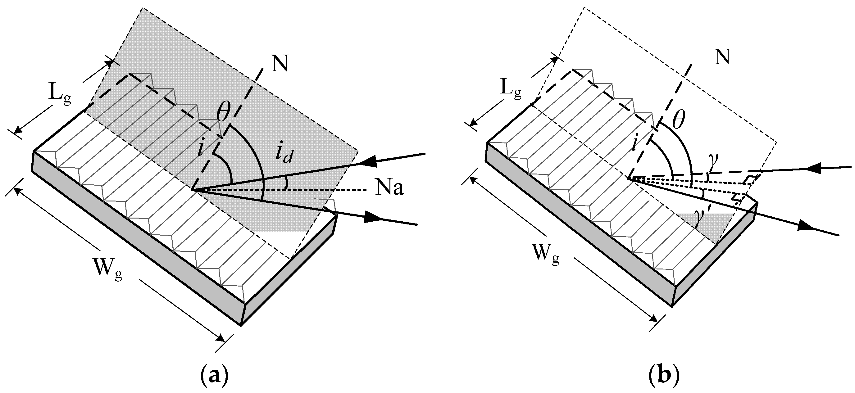
The light usually incidents on the echelle by the Littrow mode [27], which provides a greater resolving power, as shown the illustration above. However, in the strict Littrow mode, the incident rays overlap with the diffracted rays of the blazed wavelength, which limits the layout of optics. Therefore, it is necessary to introduce a certain angle to separate the two beams to form a quasi-Littrow mode. There are two ways—one is the In-plane Quasi-Littrow mode, and the other is the Off-plane Quasi-Littrow mode [28], as shown in Figure 5.
For IQLM (Figure 5a), the incident rays and diffraction rays are all in the principal plane. In OQLM (Figure 5b), the incident and diffraction rays deviate from the principal plane by small angles. Instead of the coincidence with Na in the strict Littrow mode, the incident rays deviate from Na by a small angle, both in IQLM and OQLM, which makes the optical layout easier. However, the diffraction efficiencies of these two modes have some differences. When id = 0, it is the strict Littrow mode whose diffraction efficiency is maximum. As id increases in IQLM, the peak diffraction efficiency decreases rapidly, which indicates that there is a trade-off between the efficiency and the optical layout. A small id is beneficial for diffraction efficiency, but it is easy to obstruct other optics. While in OQLM, the projections of the incident and diffraction rays on the principal plane satisfy the Littrow condition. The diffraction efficiency is cosγ times that of the strict Littrow mode. cosγ has little effect on diffraction efficiency, even when γ increased to 10°. This indicates that OQLM maintains the characteristics of the full-spectrum blaze better, taking full advantage of the light flux [29]. So, OQLM is widely accepted by most instruments.

3.2. Cross-Dispersion Layout

At OQLM, the grating equation can be expressed as:
2 d sin θ B cos γ = m λ
Due to the large blaze angle and large grating period of the echelle, the blazed wavelengths of all orders are diffracted in the same direction, causing the overlap of the diffraction wavelengths from different orders. In order to separate the overlapping orders, we need to perform secondary dispersion in the direction perpendicular to the grating dispersion, forming the cross-dispersion to obtain a two-dimensional spectrum [30], as shown in Figure 6. The cross disperser can be a prism or a grating. Commercial spectrometers usually use prisms, and astronomical instruments employ gratings more. We can define the grating dispersion as the primary dispersion and the dispersion perpendicular to the primary one as the auxiliary dispersion. The resolution of the auxiliary dispersion should be greater than the free spectral range. The arrangements of the primary and auxiliary dispersion have three modes, as shown in Figure 7. Taking a prism as the auxiliary disperser, for example, the position of the prism can be before or after the echelle, or the rays pass through the prism twice. When the rays are pre-dispersed by the prism (Figure 7a) [31,32], the incidence angles on the echelle are not uniform, which makes the calibration difficult. The layout in which rays pass through the prism twice (Figure 7c) [33,34,35,36] suffers from the same problem, but it has a higher resolving power between orders. The most common mode is that the prism is after the grating (Figure 7b) [15,37], which is easier for calibration and can meet the resolving demands for orders in most cases.

3.3. Collimating/Focusing Optics

The standard scheme of the cross-dispersion for the echelle spectrometers evolved from the Czerny–Turner (CT) structure [38,39]. As shown in Figure 7, it uses two concave spherical mirrors as the collimating mirror and the imaging mirror, respectively, at the two sides of the grating. In the traditional CT structure, the comas from the collimating and imaging mirrors cancel each other out, which effectively improves imaging quality [40]. However, in OQLM cross-dispersion optics, the rays do not enter and exit on the principal plane of the grating, so the astigmatism, coma, and spherical aberration generated by the two spherical mirrors are superimposed [41]. Therefore, compressing aberrations and improving imaging quality are the challenges for echelle spectrometers.
To overcome the influence of aberrations on the spectral resolution, multiplex alterations of optical paths are applied on the standard scheme by integrating extra optical components to the optics or by replacing the spherical mirrors with other macroshape mirrors. The astigmatism is the key influencing the resolution in the standard scheme. Wood and Lawler proposed an approach that suppressed astigmatism by rotating the ordered separation system to an orthogonal plane and prevented additional coma [42]. Xiao Fu [43] and Yin Lu [44] both added a cylindrical lens between the imaging mirror and the image plane to compress astigmatism. Yingchao Li proposed an aberration-corrected method for the echelle spectrometer based on a digital micromirror device and a photomultiplier, placing a lens group in front of the digital micromirror device [45]. Using parabolic mirrors as the collimating and imaging mirrors is another way to improve the system [46], which eliminates all the aberrations at the central wavelength. The system has much better imaging quality within a certain wavelength range, but the further away the wavelength is from the image center, the worse the image quality is. The spectral resolution difference from the nonuniform spot size is big. To overcome the inhomogeneity of the spot size, Yinxin Zhang [47] and Zengpeng Yang [48] both replaced the single imaging mirror with the three-mirror anti-astigmatism optical system. All the methods above are beneficial to optimizing the cross-dispersed optical system.

3.4. Detector

The two-dimensional spectrum of the cross-dispersion on the focal plane should be detected by detectors. Some early echelle spectrometers used the photomultiplier (PMT) [49,50,51] and photo-diode array (PDA) [52,53]. Nowadays, area array charge-coupled devices (CCD) and Complementary Metal Oxide Semiconductors (CMOS) are widely used.
When selecting a detector for the echelle spectrometer, we should consider some main parameters, such as the quantum efficiency, the image size, the effective pixels, and the pixel size. Within the wavelength range required, the higher the quantum efficiency is, the more sensitive the detector is. To capture the target spectrum in one shot, the image size ought to be big enough to cover all the monochromatic image spots that are to be measured [54]. For the primary dispersion direction, the height H of the detector should satisfy:
Δ l m = f c a m λ m c e n d cos γ cos θ B H
where Δlm is the broadening of a single order on the image plane, fcam is the focal length of the focusing optics, and λm-cen is the central wavelength of the m-th order. For the direction perpendicular to the primary dispersion, the wavelength range is λminλmax, and the width Wd of the detector should satisfy:
f c a m ( χ m a x χ m i n ) W d
where χmin and χmax are the dispersion angles at λmin and λmax, respectively.
The pixel size of the detector influences the system spectral resolution [55,56]. No matter what kind of detector is selected, we must follow the Nyquist–Shannon sampling theorem. That is, each image spot should cover at least two pixels. For more reliability, we cover three pixels and obtain:
sin i + sin θ λ cos θ f · Δ λ 3 p
where Δ λ is the spectral bandwidth of the slit image, and p is the pixel size of the detector. In the Littrow mode, the pixel size p should satisfy:
p < 2 f tan θ B 3 R
where R is the spectral resolution of the system, which is inversely proportional to the pixel size. There is a trade-off between the sensitivity of the detector and the spectral resolution.

4. Calibration

The two-dimensional monochromatic images captured by the detector need to be converted into a one-dimensional spectrum (Figure 8) calibrated with respect to the wavelength and intensity, which is called spectral restoration. The accuracy of the wavelength calibration depends on the spectral restoration algorithm. Improving the computational accuracy as well as the operating rate are always the goals of calibration algorithms.
In the early period, the wavelength position on a detector was calibrated by ray tracing with massive calculation. Later, it was optimized by mathematical methods. Nisson A. described the spectrum as its component cyclic orders and subsequently used the spectrographic optical axis as the fiduciary line to identify an unknown spectral line in terms of the position within its order cycle, with an accuracy of 1/105 [57]. McNeill proposed a method by which any line in an echelle spectrum was characterized by the ratio of l/L, where L is the distance between two arbitrary marks at opposite ends of the prism spectral slit, and l is the distance of the echelle line from one of them. Its accuracy is better than 1/106 [58]. However, the calibration accuracy and speed are still insufficient. Researchers developed a method of building a simplified optical model to establish the relationship between the wavelength and pixel position. For example, the software, called EGRAM (for echellogram), mapped the spectrograms from echelle spectrographic systems to the first order [59]. RUI Zhang deduced a detailed mathematical model suitable for real-time wavelength calibration of the refractive index of the prism, with an accuracy of 10−3 nm for the entire spectral range [60]. Sometimes, the model has errors. Lu Yin combined the ray-tracing technique with the method of EGRAM [59] to solve this problem. The accuracy of the algorithm is improved by calculating the offset distance of the principal ray from the center of the image plane in the two-dimensional vertical direction and compensating the spectral line bending from the reflecting prism, and the maximum deviation is less than one pixel [44]. Because many algorithms need to know the locations and wavelengths of hundreds of lines, G. Mirek Brandt proposed a method that required neither the pixel locations of certain spectral features nor the true order number of each diffraction order. It is a fully automatic wavelength calibration method that uses duplicate spectral features in adjacent orders to establish the scale-invariant component of the wavelength solution [61].
However, the actual image location may not be completely consistent with the theoretical wavelength coordinates, which may be caused by environmental changes (such as humidity, temperature, and atmospheric pressure), the processing of optical components, and adjustment errors. So, the model calibration is of significance. Sadler proposed a wavelength calibration method that simulated a conceptual spectrometer and could achieve sub-pixel accuracy of spectral line prediction positions in the temperature range of 5–35 °C [62], but this method ignored the effects of pressure and humidity. Rui Zhang established a spectral simplified model that could invert systematic parameters, and the deviation between the corrected actual x- and y-coordinates and the model calculation was less than one pixel [63]. Fajie Duan also proposed a time-saving simple spectral reduction algorithm. First, the least squares method (LSM) was used to associate the actual spectrogram with the theoretical model; then, the polynomial fitting method was used to improve the accuracy of the algorithm, and the wavelength error was less than 0.02 nm [64].

5. Applications

5.1. Commercial Instruments

The echelle system has been extensively used in commercial instruments because of its parallel measurement in a broadband spectral range with a high resolution and its compact size. The mainstream instruments include the inductively coupled plasma optical emission spectrometer (ICP-OES), atomic absorption spectrometry (AAS), and laser-induced breakdown spectroscopy (LIBS).
The combination of the echelle and cross-dispersion is the optimum optical scheme for ICP-OES that measures a large number of spectral lines simultaneously [65,66,67,68,69]. The spectral resolution is normally a few picometers. An echelle polychromator for ICP-OES designed by Thomas W in 1993 had a spectral range of 167–782 nm and a resolution of 0.006 nm (full width at half-maximum, FWHM) at 220 nm [66]. Shen Luan designed one that measured wavelengths from 130 nm to 800 nm, with a spectral bandwidth of 0.006 nm at 134.724 nm [65]. The near-infrared Echelle microwave-induced plasma atomic emission spectrometry (NIR-Echelle-MIP-OES) studied by J. Koch can be used for high-repetitive, high-resolved, and simultaneous spectra acquisition between 640 nm and 990 nm [67]. Chen proposed a wide spectral coverage approach with a rotating prism. The spectral range can reach 180–900 nm. Combined with ICP-OES, the wavelength precision is better than 0.01 nm [15]. Rolland-Thompson developed an approach in 2019 that can be applied to ICP-OES, and its imaging system includes primary, secondary, and tertiary tilted mirrors. The spectral resolution is up to 2.3 picometers/pixel [70].
The early AAS used hollow cathode lamps as the light source [71] and replaced the lamps to measure different chemical elements. Using continuous light as the light source directly is a challenge because it needs an optical scheme with a higher efficiency and a detector with more sensitivity [72]. The echelle cross-dispersed system provides a good solution [73]. For example, the electrothermal atomic absorption spectrometry (ETAAS) system developed by Bernard Radziuk determined simultaneous multi-elements and increased the radiation throughput [74]. Becker-Ross developed an echelle spectrometer as the research tool for the structured background in flame atomic absorption spectrometry (flame-AAS) with a spectral range of 200–465 nm [75].
LIBS requires broadband and high-resolution performance. In 1998, H.E. Bauer first proposed an approach using an echelle and an intensified charge coupled device (ICCD) in LIBS, which can simultaneously measure spectral lines in a wide wavelength range and improve the performance of analyzing samples [76]. Since then, the echelle scheme has been widely used in LIBS [77,78]. Chen Shao-jie [79] and C. Fabre [80] applied the echelle dispersion technique to LIBS successfully. A setup for LIBS and Raman spectroscopy measurements in a single unit using an echelle spectrograph system has been reported in recent years to measure minerals, archaeological artifacts, and other complex samples with minimum sample damage or consumption [81].

5.2. Astronomical Instruments

In the field of astronomy, spectral analysis is an extremely important way to observe celestial bodies. The spectral analysis determines the density, mass, movement, chemical composition, and distance from earth [82]. A high spectral resolution and broadband spectral range are the basic requirements for astronomical spectrometers. The light from deep space through a telescope is so weak that it usually takes more than one hour for an image. Spectrometers with common blazed gratings need multiple exposures for a broadband spectral range. During the longtime exposures, the state of celestial bodies may have changed. So, the capability of capturing the whole spectrum at one shot is another requisite for astronomical spectrometers. The echelle and the cross-dispersion are exactly applicable in astronomy.
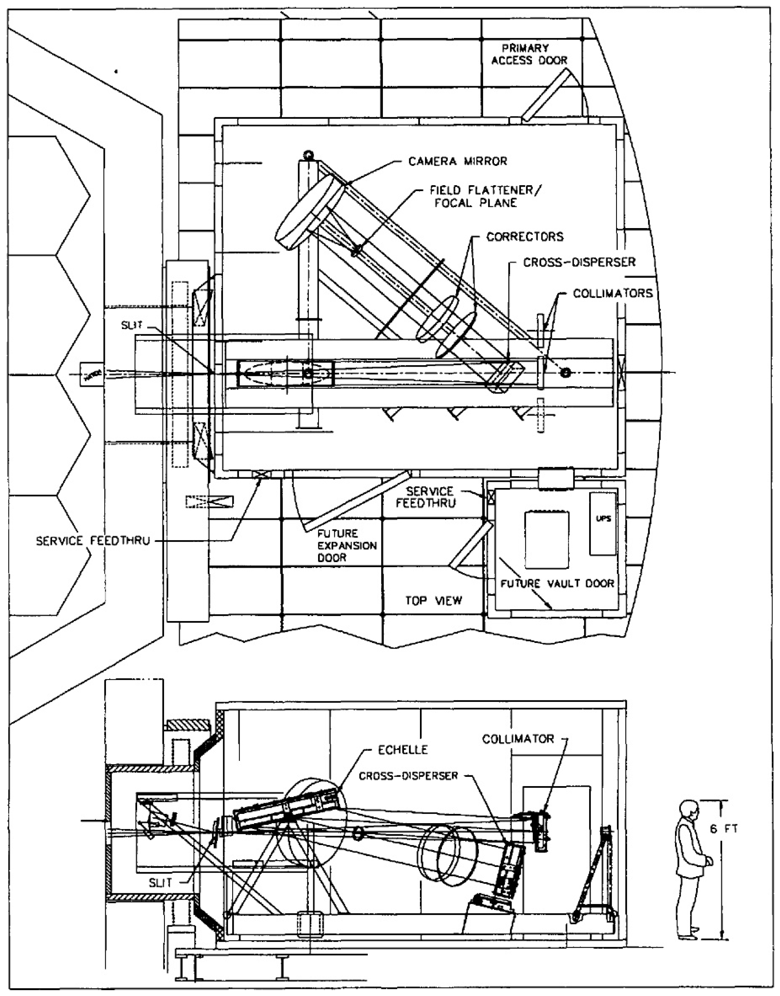
Early astronomical applications of the echelle spectrometer include the middle ultraviolet solar spectrometer from rockets [83] and the echelle spectrometer-spectrograph for the 91 cm telescope at Pine Bluff [84]. However, due to the limitation of the grating fabrication, the resolution is not high. With the improvement of the ruling technique, echelle spectrometers have been more widely used [85]. The high-resolution echelle spectrometer (HIRES) [86,87] (Figure 9) is the most representative one, which was constructed for the Keck telescope. It uses an echelle as the dispersive element, and the focal length of the collimator is much larger than that of the spectroscopic imaging mirror to reduce the image. It is difficult for the optical design to image the information from a large aperture telescope to the detector of a limited area. Therefore, the spectrometers for astronomical observation have much more complicated optics than commercial instruments. To meet the extremely high-resolution requirements, they typically have a front optical path, a collimated optical path, a cross-dispersion optical path, an imaging optical path, and an additional correction optical path.
In recent years, more and more observatories have begun to use echelle spectrometers for astronomical observations, as shown in Table 1. It can be seen that the spectral range of most spectrographs covers all of the visible spectrum and some of the near-infrared spectrum, such as EXPERT-III [88], CAFE [89], MIKE [90], and NRES [91,92,93]. There are also a few spectrometers whose spectral range only covers the near-infrared band, such as SPIRou [94,95,96]. Some spectrographs cover part of the mid-infrared spectrum, such as CRIRES+ [97,98,99,100]. Many of these spectrographs follow a concept called “white-pupil”, which was proposed by Baranne in 1972 [101]. In the white-pupil concept, the system pupil at the dispersive element is re-imaged on the entrance aperture of the camera. This pupil image is fixed at a specific position, independent of the wavelength. For example, the optical design of NEID is based on a classic white pupil layout [102]. Generally speaking, the white-pupil design offers a higher overall throughput and better image quality than conventional designs for the same resolution. For higher performance, some spectrometers use a beam splitter to split the beam into two sections so as to optimize the image quality and optical efficiency of each section individually. Some spectrometers split the beam into red and blue arms, such as G-CLEF [103,104,105], ESPRESSO [106,107,108,109], PEPSI [110,111,112,113], and SALT-HRS [114], while the light in CARMENES is separated into the visible and near-IR channels by a dichroic beam splitter centered at 0.96 µm [115,116,117]. In order to get a wider range of full spectrum coverage, some spectrographs employ several echelles with different incidence angles, such as CRIRES+. For higher spectral resolutions, we can use smaller slits, but the luminous flux is lower. Thus, the relationship between them needs to be balanced. Some spectrographs, such as CRIRES+ and IRD [118], were adjusted by an adaptive optics system to improve the performance of spectrometers.

6. Discussions and Outlook

In this review, we provided a general overview of the echelle spectroscopic technology. We discussed the characteristics of the echelle, the optical layout strategies, the key parameters of detection, the calibration methods, and the applications in commercial and astronomical instruments. Compared with the scanning-based spectrometers using common blazed gratings, echelle spectrometers have remarkable advantages. They have high spectral resolution and large optical throughput within the full spectral range. Such characteristics ensure the compact optical size and high-speed spectral analysis. These capabilities make the echelle spectrometer an appealing tool for identifying fine chemical compositions in the civilian field and studying celestial bodies in astronomy.
Commercial instruments pursue high performance at a low cost. The products need to meet the requirements of applications at an available price that most users can afford. The spectral resolution of a few picometers from ultraviolet to near infrared light is propitious for identifying metals and their isotopes. Higher spectral resolutions have fewer applications but higher costs. The current echelle spectrometers are still expensive due to the optics and the area array detector. The improvement of the optical fabrication technique for the echelle itself and the non-spherical mirrors is the key to reducing the price of optics. As for the detector, large-area, highly sensitive, and broadband CCDs or CMOSs are rapidly developing, but it is hard for the cost to drop in a short time. Therefore, the echelle cross dispersive technique is still only available in advanced equipment. On the other hand, the volume of spectrometers with echelles is too large to be portable. The development of a low-cost and portable device is the direction of the spectrometer of echelles.
For astronomical spectrometers, an extremely high performance is required, and the budget is usually adequate. So, the optics are much more complicated than those of commercial spectrometers, and the optical system consists of many lenses instead of a few mirrors. The highest obtainable spectral resolution is proportional to the grating size and even the instrument volume. Although the cost of optics is not a main limitation for the perfect optical performance, the volume influences the total budget and building difficulty greatly in the thermal IR because the price of the cooling vacuum container holding the spectrometer rises sharply as the volume increases [121]. An immersed echelle is a solution to reduce the size. It is an echelle in which the optical pass is filled up with high-refractive-index (n) material. For a given grating size, the immersed echelle has an n-fold increase in resolving power compared with the common echelle [121,122,123]. At some observatories, both the echelle and the immersed echelle are used in the spectrometer to observe different wavebands [124,125].
In the future, the echelle and cross-dispersion will continue to serve as a significant platform for the spectrometer family. It holds the promise of more applications in environmental monitoring, mineral exploration, metallurgy, biomedicine, and other fields. Furthermore, echelle spectrometers in various observatories around the world will be used to explore more diversified scientific discoveries.

7. Conclusions

Echelle grating provides high spectral resolving power and high diffraction efficiency in the broadband wavelength range by the Littrow mode. The spectrometer with a cross-dispersed echelle scheme achieves a two-dimensional spatial distribution of the spectrum by one exposure without scanning in the broadband spectral range. It is the fastest and most sensitive spectroscopic technology as of now, and it has been extensively applied in commercial and astronomical spectrometers. In the future, the echelle will have more applications in many fields.

Author Contributions

Conceptualization, Y.Z.; investigation, Y.Z., W.L. and W.D.; writing—original draft preparation, W.L. and W.D.; writing—review and editing, Y.Z., W.L. and H.Y.; supervision, Z.H. and H.Y.; funding acquisition, Y.Z. and H.Y. All authors have read and agreed to the published version of the manuscript.

Funding

This research was funded by the National Key Scientific Instrument and Equipment Development Project of China (2014YQ510403); the National Natural Science Foundation of China (NSFC) (61505143); and the Strategic Priority Research of the Chinese Academy of Sciences (CAS) (XDB09040100).

Institutional Review Board Statement

Not applicable.

Informed Consent Statement

Not applicable.

Data Availability Statement

All data generated or analyzed during this study are included in this published article.

Conflicts of Interest

The authors declare no conflict of interest.

References

  1. Neumann, W. Fundamentals of Dispersive Optical Spectroscopy Systems (Pm242); SPIE Press: Bellingham, DC, USA, 2013. [Google Scholar]
  2. Lentini, N.; Tiong, B.C.K.; Dubois, L.; Feger, T.; Coutts, D.W.; Fallscheer, C.; Schwab, C. A high resolution echelle spectrograph for exoplanet searches with small aperture telescopes. In Proceedings of the Ground-Based and Airborne Instrumentation for Astronomy VII, Austin, TX, USA, 10–14 June 2018; Volume 10702. [Google Scholar]
  3. Bourdarot, G.; Le Coarer, E.; Bonfils, X.; Alecian, E.; Rabou, P.; Magnard, Y. NanoVipa: A miniaturized high-resolution echelle spectrometer, for the monitoring of young stars from a 6U Cubesat. CEAS Space J. 2017, 9, 411–419. [Google Scholar] [CrossRef]
  4. Fantoni, R.; Almaviva, S.; Caneve, L.; Colao, F.; Maddaluno, G.; Gasior, P.; Kubkowska, M. Hydrogen isotope detection in metal matrix using double-pulse laser-induced breakdown-spectroscopy. Spectrochim. Acta Part B At. Spectrosc. 2017, 129, 8–13. [Google Scholar] [CrossRef]
  5. Miyabe, M.; Oba, M.; Jung, K.; Iimura, H.; Akaoka, K.; Kato, M.; Otobe, H.; Khumaeni, A.; Wakaida, I. Laser ablation absorption spectroscopy for isotopic analysis of plutonium: Spectroscopic properties and analytical performance. Spectrochim. Acta Part B At. Spectrosc. 2017, 134, 42–51. [Google Scholar] [CrossRef]
  6. Wang, P.; Chen, J.; Wu, X.; Tian, Y.; Zhang, R.; Sun, J.; Zhang, Z.; Wang, C.; Bai, P.; Guo, L.; et al. Determination of blood species using echelle Raman spectrometer and surface enhanced Raman spectroscopy. Spectrochim. Acta A 2022, 281, 121640. [Google Scholar] [CrossRef]
  7. Harrison, G.R.; Davis, S.P.; Robertson, H.J. Precision Measurement of Wavelengths with Echelle Spectrographs. J. Opt. Soc. Am. 1953, 43, 853–859. [Google Scholar] [CrossRef]
  8. Harrison, G.R. The Production of Diffraction Gratings: II. The Design of Echelle Gratings and Spectrographs1. JOSA 1949, 39, 522–527. [Google Scholar] [CrossRef]
  9. Harrison, G.R. The Production of Diffraction Gratings I. Development of the Ruling Art. JOSA 1949, 39, 413–426. [Google Scholar] [CrossRef]
  10. Harrison, G.R.; Loewen, E.G.; Wiley, R.S. Echelle gratings: Their testing and improvement. Appl. Opt. 1976, 15, 971–976. [Google Scholar] [CrossRef]
  11. Harrison, G.R. The diffraction grating—An opinionated appraisal. Appl. Opt. 1973, 12, 2039–2049. [Google Scholar] [CrossRef]
  12. Harrison, G.R.; Archer, J.E.; Camus, J. A Fixed-Focus Broad-Range Echelle Spectrograph of High Speed and Resolving Power. J. Opt. Soc. Am. 1952, 42, 706–709. [Google Scholar] [CrossRef]
  13. Zander, A.T.; Keliher, P.N. Examination of the Spectral Efficiency of an Echelle Grating Monochromator. Appl. Spectrosc. 1979, 33, 499–502. [Google Scholar] [CrossRef]
  14. Ying-Chao, L.; Chun-Sheng, L.; Hong-Xia, W.; Wen-Yu, J.; Liu-Zhen, S.; Yu-Qing, Y.; Guang, Y.; Di, T. Research on Detection Technology of Inductively Coupled Plasma Optical Emission Spectrometer Based on Digital Micromirror Device. Chin. J. Anal. Chem. 2022, 50, 1150–1157. [Google Scholar]
  15. Chen, S.; Tang, Y.; Bayanheshig, X.; Qi, X.; Zhu, W. A new type of wide spectral coverage echelle spectrometer design for ICP-AES. In Optical Design and Testing V; SPIE: Bellingham, DC, USA, 2012; Volume 8557. [Google Scholar]
  16. Becker-Ross, H.; Florek, S.; Franken, H.; Radziuk, B.; Zeiher, M. A scanning echelle monochromator for ICP-OES with dynamic wavelength stabilization and CCD detection. J. Anal. Atom. Spectrom. 2000, 15, 851–861. [Google Scholar] [CrossRef]
  17. Fichet, P.; Tabarant, M.; Salle, B.; Gautier, C. Comparisons between LIBS and ICP/OES. Anal. Bioanal. Chem. 2006, 385, 338–344. [Google Scholar] [CrossRef] [PubMed]
  18. Sedykh, E.M.; Gromyak, I.N.; Lorents, K.A.; Skripnik, A.Y.; Kolotov, V.P. A Methodological Approach to the Analysis of Rocks and Meteorites by Inductively Coupled Plasma Atomic Emission Spectrometry. J. Anal. Atom. Spectrom. 2019, 74, 393–400. [Google Scholar] [CrossRef]
  19. Harnly, J.M. The future of atomic absorption spectrometry: A continuum source with a charge coupled array detector. J. Anal. Atom. Spectrom. 1999, 14, 137–146. [Google Scholar] [CrossRef]
  20. Welz, B.; Becker-Ross, H.; Florek, S.; Heitmann, U.; Vale, M.G.R. High-resolution continuum-source atomic absorption spectrometry: What can we expect? J. Brazil. Chem. Soc. 2003, 14, 220–229. [Google Scholar] [CrossRef] [Green Version]
  21. Shameem, K.M.M.; Dhanada, V.S.; George, S.D.; Kartha, V.B.; Santhosh, C.; Unnikrishnan, V.K. Assessing the feasibility of a low-throughput gated echelle spectrograph for Laser-induced Breakdown spectroscopy (LIBS)-Raman measurements at standoff distances. Opt. Laser Technol. 2022, 153, 108264. [Google Scholar] [CrossRef]
  22. Taleb, A.; Shen, C.; Mory, D.; Cieślik, K.; Merk, S.; Aziz, M.R.; Caricato, A.P.; Gerhard, C.; Pelascini, F.; Hermann, J. Echelle spectrometer calibration by means of laser plasma. Spectrochim. Acta. Part B At. Spectrosc. 2021, 178, 106144. [Google Scholar] [CrossRef]
  23. Rao, A.P.; Jenkins, P.R.; Auxier, J.D.; Shattan, M.B.; Patnaik, A.K. Enabling orders of magnitude sensitivity improvement for quantification of Ga in a Ce matrix with a compact Echelle spectrometer. J. Anal. Atom. Spectrom. 2022, 37, 1975–1980. [Google Scholar] [CrossRef]
  24. Lizon, J.L.; Klein, B.; Oliva, E.; Löwinger, T.; Escude, G.A.; Baade, D.; Bristow, P.; Dorn, R.J.; Follert, R.; Grunhut, J.; et al. Opto-mechanical design of a new Cross Dispersion Unit for the CRIRES plus high resolution spectrograph for the VLT. In Proceedings of the Ground-Based and Airborne Instrumentation for Astronomy V, Montréal, QC, Canada, 22–26 June 2014; Volume 9147. [Google Scholar]
  25. Lotem, H. Littrow-mounted diffraction grating cavity. Appl Opt. 1994, 33, 930–934. [Google Scholar] [CrossRef] [PubMed]
  26. Lu, P.P.; Sun, K.X.; Byer, R.L.; Britten, J.A.; Hoaglan, C.R. Precise diffraction efficiency measurements of large-area greater-than-99%-efficient dielectric gratings at the Littrow angle. Opt. Lett. 2009, 34, 1708. [Google Scholar] [CrossRef] [PubMed]
  27. Masters, R.; Hsiech, C.; Pardue, H.L. Advantages of an off-Littrow mounting of an echelle grating. Appl. Opt. 1988, 27, 3895–3897. [Google Scholar] [CrossRef] [PubMed]
  28. Schroeder, D.J. Design considerations for astronomical echelle spectrographs. Publ. Astron. Soc. Pac. 1970, 82, 1253. [Google Scholar] [CrossRef]
  29. Schroeder, D.J.; Hilliard, R.L. Echelle efficiencies: Theory and experiment. Appl. Opt. 1980, 19, 2833–2841. [Google Scholar] [CrossRef]
  30. Wang, X.-L.; Chang, L.; Wang, L.; Ji, H.-X.; Xian, H.; Tang, Z.; Xin, Y.-X.; Wang, C.-J.; He, S.-S.; Zhang, J.-J.; et al. The Coude Echelle Spectrograph for the Lijiang 1.8m telescope. Res. Astron. Astrophys. 2020, 20, 032. [Google Scholar] [CrossRef]
  31. Lizon, J.L.; Klein, B.; Molina-Conde, I.; Oliva, E.; Escude, G.A.; Bristow, P.; Dorn, R.J.; Follert, R.; Hatzes, A.; Heiter, U.; et al. Very accurate cryogenic mechanisms for CRIRES. In Proceedings of the Optical and Infrared Interferometry and Imaging VI, Austin, TX, USA, 11–15 June 2018; Volume 10701. [Google Scholar]
  32. Kerber, F.; Frey, B.J.; Leviton, D.B.; Bristow, P.; Rosa, M.R. Calibration of the ZnSe pre-disperser on ESO’s cryogenic IR echelle spectrograph (CRIRES): Comparison of the first results from CRIRES and the laboratory data from CHARMS. Proc. SPIE-Int. Soc. Opt. Eng. 2006, 6269, 1317–1328. [Google Scholar]
  33. Farsad, M. A design cycle for echelle spectrometers. In Proceedings of the International Optical Design Conference, Denver, CO, USA, 9–13 July 2017; Volume 10590. [Google Scholar]
  34. Ge, J.; Angel, J.; Jacobsen, B.; Woolf, N.; Fugate, R.Q.; Black, J.H.; Lloyd-Hart, M. An optical ultrahigh-resolution cross-dispersed echelle spectrograph with adaptive optics. Publ. Astron. Soc. Pac. 2002, 114, 879–891. [Google Scholar] [CrossRef] [Green Version]
  35. Oliva, E.; Origlia, L.; Maiolino, R.; Gennari, S.; Biliotti, V.; Rossetti, E.; Baffa, C.; Leone, F.; Montegriffo, P.; Lolli, M.; et al. GIANO: An ultra-stable IR echelle spectrometer optimized for high precision radial velocity measurements and for high throughput low resolution spectroscopy. In Ground-Based Instrumentation for Astronomy, PTS 1-3; Springer: Berlin/Heidelberg, Germany, 2004; Volume 5492, pp. 1274–1279. [Google Scholar]
  36. Tull, R.G.; Macqueen, P.J.; Sneden, C.; Lambert, D.L. The High-Resolution Cross-Dispersed Echelle White-Pupil Spectrometer of the McDonald Observatory 2.7-m Telescope. Publ. Astron. Soc. Pac. 1995, 107, 251–264. [Google Scholar] [CrossRef] [Green Version]
  37. Sun, C.; Yang, J.; Zhu, J.; Ma, T.; Feng, S.; Song, N.; Guo, X.; Guo, H. Optical design of echelle spectrometer with ultra-wide wavelength range and high resolution. Opt. Precis. Eng. 2021, 29, 45–53. [Google Scholar] [CrossRef]
  38. Wu, S.; Wang, T.; Huang, C.; Gu, J.; Yu, L.; Xue, H.; Shen, Y. Advanced optical design of Czerny-Turner spectrometer with high flux and low aberration in broadband. Appl. Opt. 2022, 61, 3077. [Google Scholar] [CrossRef] [PubMed]
  39. Zhou, Q.; Zou, Z. Astigmatism-free Czerny–Turner spectrometer with a low f-number by a bicylinder lens. Appl. Opt. 2022, 61, 7985. [Google Scholar] [CrossRef] [PubMed]
  40. Shafer, A.B.; Megill, L.R.; Droppleman, L. Optimization of the Czerny-Turner Spectrometer. J. Opt. Soc. Am. 1964, 54, 879–886. [Google Scholar] [CrossRef]
  41. Zhang, Y.; Yang, H.; Huang, Z.; Jin, G. Optical Path Difference in Off-Plane Quasi-Littrow Dispersion Mountings. Spectrosc. Spect. Anal. 2013, 33, 1992–1996. [Google Scholar]
  42. Wood, M.P.; Lawler, J.E. Aberration-corrected echelle spectrometer for measuring ultraviolet branching fractions of iron-group ions. Appl. Opt. 2012, 51, 8407–8412. [Google Scholar] [CrossRef] [PubMed]
  43. Fu, X.; Duan, F.; Jiang, J.; Huang, T.; Ma, L.; Lv, C. Astigmatism-corrected echelle spectrometer using an off-the-shelf cylindrical lens. Appl. Opt. 2017, 56, 7861–7868. [Google Scholar] [CrossRef]
  44. Yin, L.; Yang, J.; Lu, Y.; Zhang, R.; Sun, C.; Cui, J. High-accuracy spectral reduction algorithm for the echelle spectrometer. Appl. Opt. 2016, 55, 3574–3581. [Google Scholar] [CrossRef]
  45. Li, Y.; Jiang, W.; Li, C.; Ma, Z.; Yang, Y.; Tian, D. Spectral reduction model for an echelle spectrometer based on a digital micromirror device and photomultiplier. Appl. Opt. 2021, 60, 9101–9109. [Google Scholar] [CrossRef]
  46. Pfeiffer, M.J.; Frank, C.; Baumüller, D.; Fuhrmann, K.; Gehren, T. FOCES—A fibre optics Cassegrain échelle spectrograph. Astron. Astrophys. Suppl. 1998, 130, 381–393. [Google Scholar] [CrossRef]
  47. Zhang, Y.; Duan, W.; Li, W. Design of Echelle Spectrometer with a Three-Mirror Anastigmat System. J. Tianjin Univ. 2022, 55, 519–526. [Google Scholar]
  48. Yang, Z.; Li, Z.; Pu, E.; Yan, L.; Wang, C.; Chen, L.; Li, P.; Yang, W.; Zhang, Y. High-Resolution Echelle Grating Spectrometer Based on Off-Axis Three-Mirror Reflective Optical System. Acta Opt. Sin. 2021, 41, 2212001. [Google Scholar]
  49. Zander, A.T.; Miller, M.H.; Hendrick, M.S.; Eastwood, D. Spectral Efficiency of the SpectraSpan III Echelle Grating Spectrometer. Appl. Spectrosc. 1985, 39, 1–5. [Google Scholar] [CrossRef]
  50. Cothran, C.D.; Fung, J.; Brown, M.R.; Schaffer, M.J. Fast high resolution echelle spectroscopy of a laboratory plasma. Rev. Sci. Instrum. 2006, 77, 063504. [Google Scholar] [CrossRef]
  51. Zhang, R.; Ren, W.; Xu, Z.; Wang, H.; Jiang, J.; Wang, Y.; Luo, X. Single-pixel echelle spectrometer based on compressive sensing. Optik 2021, 240, 166813. [Google Scholar] [CrossRef]
  52. Karanassios, V.; Horlick, G. Spectral Characteristics of a New Spectrometer Design for Atomic Emission Spectroscopy. Appl. Spectrosc. 1986, 40, 813–820. [Google Scholar] [CrossRef]
  53. Baldwin, D.P.; Zamzow, D.S.; Eckels, D.E.; Miller, G.P. AOTF-echelle spectrometer for air-ICP-AES continuous emission monitoring of heavy metals and actinides. Environ. Monit. Remediat. Technol. 1999, 3534, 478–487. [Google Scholar]
  54. Shannone, C. A Mathematical Theory of Communication; Wiley-IEEE Press: Hoboken, NJ, USA, 1948. [Google Scholar]
  55. Li, Y.; Duan, F.; Fu, X.; Huang, T. Optical Design of Small High Resolution Echelle Spectrograph. Chin. J. Sens. Actuators 2017, 30, 1139–1144. [Google Scholar]
  56. Becker-Ross, H.; Florek, S.V. Echelle spectrometers and charge-coupled devices. Spectrochim. Acta Part B At. Spectrosc. 1997, 52, 1367–1375. [Google Scholar] [CrossRef]
  57. Finkelstein, N.A. The Measurement of Wavelength in Echelle Spectra. J. Opt. Soc. Am. 1953, 43, 90. [Google Scholar] [CrossRef]
  58. Mcneill, J.J. Wavelength Measurement in Echelle Spectra. J. Opt. Soc. Am. 1959, 49, 441. [Google Scholar] [CrossRef]
  59. Dantzler, A.A. Echelle spectrograph software design aid. Appl. Opt. 1985, 24, 4504. [Google Scholar] [CrossRef] [PubMed]
  60. Zhang, R.; Yin, L.; Li, X.; Cui, J.; Yang, J.; Sun, C. Wavelength calibration model for prism-type echelle spectrometer by reversely solving prism’s refractive index in real time. Appl. Opt. 2016, 55, 4153–4158. [Google Scholar] [CrossRef]
  61. Brandt, G.M.; Brandt, T.D.; Mccully, C. Automatic Échelle Spectrograph Wavelength Calibration. Astron. J. 2020, 160, 25. [Google Scholar] [CrossRef]
  62. Sadler, D.A.; Littlejohn, D.; Perkins, C.V. Automatic wavelength calibration procedure for use with an optical spectrometer and array detector. J. Anal. Atom. Spectrom. 1995, 10, 253–257. [Google Scholar] [CrossRef]
  63. Zhang, R.; Li, X.; Cui, J. Establishment and correction of an Echelle cross-prism spectrogram reduction model. Opt. Commun. 2017; 403, 401–407. [Google Scholar]
  64. Duan, F.; Qin, Y.; Fu, X.; Ma, L.; Huang, T.; Zhang, C. Simple spectral reduction algorithm used for the echelle spectrometer. Appl. Opt. 2018, 57, 8921–8927. [Google Scholar] [CrossRef] [PubMed]
  65. Luan, S.; Schleicher, R.G.; Pilon, M.J.; Bulman, F.D.; Coleman, G.N. An echelle polychromator for inductively coupled plasma optical emission spectroscopy with vacuum ultraviolet wavelength coverage and charge injection device detection. Spectrochim. Acta Part B At. Spectrosc. 2001, 56, 1143–1157. [Google Scholar] [CrossRef]
  66. Barnard, T.W.; Crockett, M.I.; Ivaldi, J.C.; Lundberg, P.L. Design and evaluation of an echelle grating optical system for ICP-OES. Anal. Chem. 1993, 65, 1225–1230. [Google Scholar] [CrossRef]
  67. Koch, J.; Okruss, M.; Franzke, J.; Florek, S.V.; Niemax, K.; Becker-Ross, H. Element-selective detection of gas chromatographic eluates by near infrared Échelle optical emission spectrometry on microwave-induced plasmas. Spectrochim. Acta Part B At. Spectrosc. 2004, 59, 199–207. [Google Scholar] [CrossRef]
  68. Zander, A.T.; Chien, R.L.; Cooper, C.B.; Wilson, P.V. An image-mapped detector for simultaneous ICP-AES. Anal. Chem. 1999, 71, 3332–3340. [Google Scholar] [CrossRef]
  69. Pilon, M.J.; Denton, M.B.; Schleicher, R.G.; Moran, P.M.; Smith, S.B. Evaluation of a New Array Detector Atomic Emission Spectrometer for Inductively Coupled Plasma Atomic Emission Spectroscopy. Appl. Spectrosc. 1990, 44, 1613–1620. [Google Scholar] [CrossRef]
  70. Rolland-Thompson, J.; Bauer, A.; Yates, D.; Farsad, M. Echelle Spectrometer for Inductively Coupled Plasma Optical Emission Spectroscopy (ICP-OES), Has Imaging System Comprises Primary, Secondary, and Tertiary Tilted Mirrors. U.S. Patent US546397P, 16 August 2019. [Google Scholar]
  71. Salin, E.D.; Ingle, J.D. Performance of a time multiplex multiple slit multielement flame atomic absorption spectrometer. Anal. Chem. 1978, 50, 1745–1752. [Google Scholar] [CrossRef]
  72. Sneddon, J.; Farah, B.D.; Farah, K.S. Multielement Atomic Absorption Spectrometry: A Historical Perspective. Microchem. J. 1993, 48, 318–325. [Google Scholar] [CrossRef]
  73. Hamly, J.M. Multielement Atomic Absorption with a Continuum Source. Anal. Chem. 1986, 58, 933A–943A. [Google Scholar] [CrossRef]
  74. Radziuk, B.; Rdel, G.; Stenz, H.; Becker-Ross, H.; Florek, S. Spectrometer system for simultaneous multi-element electrothermal atomic absorption spectrometry using line sources and Zeeman-effect background correction. J. Anal. Atom. Spectrom. 1995, 10, 127–136. [Google Scholar] [CrossRef]
  75. Becker-Ross, H.; Okruss, M.; Florek, S.; Heitmann, U.; Huang, M.D. Echelle-spectrograph as a tool for studies of structured background in flame atomic absorption spectrometry. Spectrochim. Acta. Part B At. Spectrosc. 2002, 57, 1493–1504. [Google Scholar] [CrossRef]
  76. Bauer, H.E.; Leis, F.; Niemax, K. Laser induced breakdown spectrometry with an echelle spectrometer and intensified charge coupled device detection. Spectrochim. Acta. Part B At. Spectrosc. 1998, 53, 1815–1825. [Google Scholar] [CrossRef]
  77. Fichet, P.; Menut, D.; Brennetot, R.; Vors, E.; Rivoallan, A. Analysis by laser-induced breakdown spectroscopy of complex solids, liquids, and powders with an echelle spectrometer. Appl. Opt. 2003, 42, 6029–6035. [Google Scholar] [CrossRef]
  78. Hoehse, M.; Mory, D.; Florek, S.; Weritz, F.; Gornushkin, I.; Panne, U. A combined laser-induced breakdown and Raman spectroscopy Echelle system for elemental and molecular microanalysis. Spectrochim. Acta Part B At. Spectrosc. 2009, 64, 1219–1227. [Google Scholar] [CrossRef]
  79. Chen, S.; Qi, X.; Guo, T.Y.; Xia, Ù.C.H. A Portable Echelle Spectrograph Design for Laser-induced Breakdown Spectrometry. Chin. J. Lumin. 2013; 34, 672–677. [Google Scholar]
  80. Fabre, C.; Dubessy, J.; Boiron, M.; Brennetot, R.; Fichet, P.; Vors, E.; Lacour, J.; Rivoallan, A. A LIBS spectral database obtained in Martian conditions with an echelle spectrometer for in situ analysis of Mars soils and rocks. In Laser Induced Plasma Spectroscopy and Applications; Optical Society of America: Washington, DC, USA, 2002; p. E3. [Google Scholar]
  81. Shameem, K.M.; Dhanada, V.S.; Harikrishnan, S.; George, S.D.; Kartha, V.B.; Santhosh, C.; Unnikrishnan, V.K. Echelle LIBS-Raman system: A versatile tool for mineralogical and archaeological applications. Talanta 2020, 208, 120482. [Google Scholar] [CrossRef]
  82. Massey, P.; Hanson, M.M. Astronomical Spectroscopy. In Planets, Stars and Stellar Systems: Volume 2: Astronomical Techniques, Software, and Data; Oswalt, T.D., Bond, H.E., Eds.; Springer: Dordrecht, The Netherlands, 2013; pp. 35–98. [Google Scholar]
  83. Tousey, R.; Purcell, J.D.; Garrett, D.L. An echelle spectrograph for middle ultraviolet solar spectroscopy from rockets. Appl. Opt. 1967, 6, 365–372. [Google Scholar] [CrossRef]
  84. Schroeder, D.J. An Echelle Spectrometer-Spectrograph for Astronomical Use. Appl. Opt. 1967, 6, 1976–1980. [Google Scholar] [CrossRef] [PubMed]
  85. Tousey, R. Highlights of twenty years of optical space research. Appl. Opt. 1967, 6, 2044–2069. [Google Scholar] [CrossRef] [PubMed]
  86. Epps, H.W.; Vogt, S.S. Extremely achromatic f/1.0 all-spherical camera constructed for the high-resolution echelle spectrometer of the Keck telescope. Appl. Opt. 1993, 32, 6270–6279. [Google Scholar] [CrossRef] [PubMed]
  87. Vogt, S.S.; Allen, S.L.; Bigelow, B.C.; Bresee, L.; Brown, W.E.; Cantrall, T.; Conrad, A.; Couture, M.; Delaney, C.; Epps, H.W.; et al. HIRES: The high-resolution echelle spectrometer on the Keck 10-m Telescope. In Instrumentation in Astronomy VIII; SPIE: Bellingham, DC, USA, 1994. [Google Scholar]
  88. Ge, J.; Zhao, B.; Powell, S.; Wang, J.; Fletcher, A.; Chang, L.; Groot, J.; Wan, X.; Jakeman, H.; Myers, D.; et al. Design and Performance of a New Generation, Compact, Low Cost, Very High Doppler Precision and Resolution Optical Spectrograph. In Proceedings of the Ground-Based and Airborne Instrumentation for Astronomy IV, Edinburgh, UK, 26–30 June 2016; Volume 8446. [Google Scholar]
  89. Aceituno, J.; Sánchez, S.F.; Grupp, F.; Lillo, J.; Hernán-Obispo, M.; Benitez, D.; Montoya, L.M.; Thiele, U.; Pedraz, S.; Barrado, D.; et al. CAFE: Calar Alto Fiber-fed Echelle spectrograph. Astron. Astrophys. 2013, 552, A31. [Google Scholar] [CrossRef] [Green Version]
  90. Bernstein, R.A.; Shectman, S.A.; Gunnels, S.; Mochnacki, S.; Athey, A. MIKE: A double echelle spectrograph for the Magellan Telescopes at Las Campanas Observatory. In Instrument Design & Performance for Optical/Infrared Ground-Based Telescopes, PTS 1-3; SPIE: Bellingham, DC, USA, 2003; Volume 4841, pp. 1694–1704. [Google Scholar]
  91. Eastman, J.D.; Brown, T.M.; Hygelund, J.; van Eyken, J.; Tufts, J.R.; Barnes, S. NRES: The Network of Robotic Echelle Spectrographs. In Proceedings of the Ground-Based and Airborne Instrumentation for Astronomy V, Montréal, QC, Canada, 22–26 June 2014; Volume 9147. [Google Scholar]
  92. Siverd, R.J.; Brown, T.M.; Hygelund, J.; Henderson, T.; Tufts, J.R.; Eastman, J.D.; van Eyken, J.; Barnes, S. NRES: The Network of Robotic Echelle Spectrographs. In Proceedings of the Ground-Based and Airborne Instrumentation for Astronomy IV, Edinburgh, UK, 26–30 June 2016; Volume 9908. [Google Scholar]
  93. Siverd, R.J.; Brown, T.M.; Barnes, S.; Bowman, M.K.; De Vera, J.; Foale, S.; Harbeck, D.R.; Henderson, T.; Hygelund, J.; Kirby, A.; et al. NRES: The Network of Robotic Echelle Spectrographs. In Proceedings of the Ground-based and Airborne Instrumentation for Astronomy VII, Austin, TX, USA, 10–14 June 2018; Volume 10702. [Google Scholar]
  94. Thibault, S.; Rabou, P.; Donati, J.F.; Desaulniers, P.; Dallaire, X.; Artigau, E.; Pepe, F.; Micheau, Y.; Vallée, P.; Barrick, G.; et al. SPIRou@ CFHT: Spectrograph Optical Design. In Proceedings of the Ground-Based and Airborne Instrumentation for Astronomy IV, Edinburgh, UK, 26–30 June 2016; Volume 8446. [Google Scholar]
  95. Donati, J.F.; Kouach, D.; Lacombe, M.; Baratchart, S.; Doyon, R.; Delfosse, X.; Artigau, É.; Moutou, C.; Hébrard, G.; Bouchy, F.; et al. SPIRou: A nIR spectropolarimeter/high-precision velocimeter for the CFHT. In Handbook of Exoplanets; Deeg, H.J., Belmonte, J.A., Eds.; Springer: Cham, Swizerland, 2018; ISBN 978-3-319-30648-3. [Google Scholar]
  96. Artigau, É.; Kouach, D.; Donati, J.-F.; Doyon, R.; Delfosse, X.; Baratchart, S.; Lacombe, M.; Moutou, C.; Rabou, P.; Parès, L.P.; et al. SPIRou: The near-infrared spectropolarimeter/high-precision velocimeter for the Canada-France-Hawaii telescope. In Proceedings of the Ground-Based and Airborne Instrumentation for Astronomy V, Montréal, QC, Canada, 22–26 June 2014; Volume 9147. [Google Scholar]
  97. Oliva, E.; Tozzi, A.; Ferruzzi, D.; Origlia, L.; Hatzes, A.; Follert, R.; Lowinger, T.; Piskunov, N.; Heiter, U.; Lockhart, M.; et al. Concept and optical design of the cross-disperser module for CRIRES. In Proceedings of the Ground-Based and Airborne Instrumentation for Astronomy V, Montréal, QC, Canada, 22–26 June 2014; Volume 9147. [Google Scholar]
  98. Brucalassi, A.; Dorn, R.J.; Follert, R.; Hatzes, A.; Bristow, P.; Seemann, U.; Cumani, C.; Eschbaumer, S.; Haimerl, A.; Haug, M.; et al. Full System Test and early Preliminary Acceptance Europe results for CRIRES. In Proceedings of the Ground-based and Airborne Instrumentation for Astronomy VII, Austin, TX, USA, 10–14 June 2018; Volume 10702. [Google Scholar]
  99. Follert, R.; Taubert, D.; Hollandt, J.; Monte, C.; Oliva, E.; Seemann, U.; Löwinger, T.; Anwand-Heerwart, H.; Schmidt, C.; Dorn, R.J.; et al. Characterizing the cross dispersion reflection gratings of CRIRES. In Proceedings of the Advances in Optical and Mechanical Technologies for Telescopes and Instrumentation II, Edinburgh, UK, 26 June–1 July 2016; Volume 9912. [Google Scholar]
  100. Dorn, R.J.; Follert, R.; Bristow, P.; Cumani, C.; Eschbaumer, S.; Grunhut, J.; Haimerl, A.; Hatzes, A.; Heiter, U.; Hinterschuster, R.; et al. The “ plus “ for CRIRES: Enabling better science at infrared wavelength and high spectral resolution at the ESO VLT. In Proceedings of the Ground-based and Airborne Instrumentation for Astronomy VI, Edinburgh, UK, 26–30 June 2016; Volume 9908. [Google Scholar]
  101. Baranne, A. Equipement spectrographique du foyer coudé du télescope de 3.60 mètres. Etude de faisabilité d’un spectrographe universel. In Proceedings of the ESO/CERN Conference on Auxiliary Instrumentation for Large Telescopes, Geneva, Switzerland, 2–5 May 1972; pp. 227–239. [Google Scholar]
  102. Schwab, C.; Rakich, A.; Gong, Q.; Mahadevan, S.; Halverson, S.P.; Roy, A.; Terrien, R.C.; Robertson, P.M.; Hearty, F.R.; Levi, E.I.; et al. Design of NEID, an extreme precision Doppler spectrograph for WIYN. In Proceedings of the Ground-based and Airborne Instrumentation for Astronomy VI, Edinburgh, UK, 26–30 June 2016; Volume 9908. [Google Scholar]
  103. Mueller, M.; Baldwin, D.; Bean, J.; Bergner, H.; Bigelow, B.; Chun, M.Y.; Crane, J.; Foster, J.; Fűrész, G.; Gauron, T.; et al. The Opto-Mechanical Design of the GMT-Consortium Large Earth Finder (G-CLEF). In Proceedings of the Ground-based and Airborne Instrumentation for Astronomy VII, Austin, TX, USA, 10–14 June 2018; Volume 10702. [Google Scholar]
  104. Szentgyorgyi, A.; Baldwin, D.; Barnes, S.; Bean, J.; Ben-Ami, S.; Brennan, P.; Budynkiewicz, J.; Chun, M.Y.; Conroy, C.; Crane, J.D.; et al. The GMT-Consortium Large Earth Finder (G-CLEF): An optical echelle spectrograph for the Giant Magellan Telescope (GMT). In Proceedings of the Ground-based and Airborne Instrumentation for Astronomy VII, Austin, TX, USA, 10–14 June 2018; Volume 10702. [Google Scholar]
  105. Ben-Ami, S.; Crane, J.D.; Evans, I.; Mcmuldroch, S.; Mueller, M.; Podgorski, W.; Szentgyorgyi, A. The optical design of the G-CLEF Spectrograph: The first light instrument for the GMT. In Proceedings of the Ground-based and Airborne Instrumentation for Astronomy VII, Austin, TX, USA, 10–14 June 2018; Volume 10702. [Google Scholar]
  106. Pepe, F.A.; Cristiani, S.; Rebolo Lopez, R.; Santos, N.C.; Amorim, A. ESPRESSO: The Echelle spectrograph for rocky exoplanets and stable spectroscopic observations. In Proceedings of the Ground-Based and Airborne Instrumentation for Astronomy III, San Diego, CA, USA, 27 June–2 July 2010; Volume 7735. [Google Scholar]
  107. Spanò, P.; Mégevand, D.; Herreros, J.M.; Zerbi, F.M.; Cabral, A.; Di Marcantonio, P.; Lovis, C.; Cristiani, S.; Rebolo, R.; Santos, N.; et al. Optical design of the ESPRESSO spectrograph at VLT. In Proceedings of the Ground-Based and Airborne Instrumentation for Astronomy III, San Diego, CA, USA, 27 June–2 July 2010; Volume 7735. [Google Scholar]
  108. Pepe, F.; Molaro, P.; Cristiani, S.; Rebolo, R.; Santos, N.; Dekker, H.; Mégevand, D.; Zerbi, F.; Cabral, A.; Di Marcantonio, P.; et al. ESPRESSO: The next European exoplanet hunter. Astron. Nachr. 2014, 335, 8–20. [Google Scholar] [CrossRef] [Green Version]
  109. Lizon, J.L.; Dekker, H.; Manescau, A.; Megevan, D.; Pepe, F.A.; Riva, M. A large mosaic echelle grating for ESPRESSO spectrograph. In Proceedings of the Optical and Infrared Interferometry and Imaging VI, Austin, TX, USA, 11–15 June 2018; Volume 10701. [Google Scholar]
  110. Pallavicini, R.; Zerbi, F.M.; Spano, P.; Conconi, P.; Mazzoleni, R.; Molinari, E.; Strassmeier, K.G. The ICE spectrograph for PEPSI at the LBT: Preliminary optical design. In Instrument Design & Performance for Optical/infrared Ground-based Telescopes, PTS 1-3; SPIE: Bellingham, DC, USA, 2003; Volume 4841, pp. 1345–1356. [Google Scholar]
  111. Strassmeier, K.G.; Woche, M.; Ilyin, I.; Popow, E.; Bauer, S.-M.; Dionies, F.; Fechner, T.; Weber, M.; Hofmann, A.; Storm, J.; et al. PEPSI: The Potsdam Echelle Polarimetric and Spectroscopic Instrument for the LBT. In Ground-based and Airborne Instrumentation for Astronomy II, PTS 1-4; SPIE: Bellingham, DC, USA, 2008; Volume 7014. [Google Scholar]
  112. Strassmeier, K.; Ilyin, I.; Järvinen, A.; Weber, M.; Woche, M.; Barnes, S.I.; Bauer, S.-M.; Beckert, E.; Bittner, W.; Bredthauer, R.; et al. PEPSI: The high-resolution échelle spectrograph and polarimeter for the Large Binocular Telescope. Astron. Nachr. 2015, 336, 324–361. [Google Scholar] [CrossRef] [Green Version]
  113. Strassmeier, K.G.; Ilyin, I.; Weber, M.; Järvinen, A.; Woche, M.; Järvinen, S.; Sablowski, D.; Mallonn, M.; Keles, E.; Carroll, T.; et al. Want a PEPSI? Performance status of the recently commissioned high-resolution spectrograph and polarimeter for the 2 × 8.4 m Large Binocular Telescope. In Proceedings of the Ground-based and Airborne Instrumentation for Astronomy VII, Austin, TX, USA, 10–14 June 2018; Volume 10702. [Google Scholar]
  114. Crause, L.A.; Sharples, R.M.; Bramall, D.G.; Schmoll, J.; Clark, P.; Younger, E.J.; Tyas, L.M.; Ryan, S.G.; Brink, J.D.; Strydom, O.J.; et al. Performance of the Southern African Large Telescope (SALT) High Resolution Spectrograph (HRS). In Proceedings of the Ground-Based and Airborne Instrumentation for Astronomy V, Montréal, QC, Canada, 22–26 June 2014; Volume 9147. [Google Scholar]
  115. Pinto, M.T.; Chanumolu, A.; Quirrenbach, A.; Reffert, S.; Zechmeister, M.; Bauer, F. Physical modeling of echelle spectrographs: The CARMENES case study. In Proceedings of the Modeling, Systems Engineering, and Project Management for Astronomy VIII, Austin, TX, USA, 10–12 June 2018; Volume 10705. [Google Scholar]
  116. Quirrenbach, A.; Amado, P.J.; Ribas, I.; Reiners, A.; Caballero, J.A.; Seifert, W.; Aceituno, J.; Azzaro, M.; Baroch, D.; Barrado, D.; et al. CARMENES: High-resolution spectra and precise radial velocities in the red and infrared. In Proceedings of the Ground-based and Airborne Instrumentation for Astronomy VII, Austin, TX, USA, 10–14 June 2018; Volume 10702. [Google Scholar]
  117. Seifert, W.; Xu, W.; Stahl, O.; Hagen, H.J.; Carrasco, M.S.; Veredas, G.; Caballero, J.A.; Guardia, J.; Helmling, J.; Hernandez, L.; et al. CARMENES: The VIS channel spectrograph in operation. In Proceedings of the Ground-based and Airborne Instrumentation for Astronomy VI, Edinburgh, UK, 26–30 June 2016; Volume 9908. [Google Scholar]
  118. Kotani, T.; Tamura, M.; Nishikawa, J.; Ueda, A.; Kuzuhara, M.; Omiya, M.; Hashimoto, J.; Ishizuka, M.; Hirano, T.; Suto, H.; et al. The infrared Doppler (IRD) instrument for the Subaru telescope: Instrument description and commissioning results. In Proceedings of the Ground-based and Airborne Instrumentation for Astronomy VII, Austin, TX, USA, 10–14 June 2018; Volume 10702. [Google Scholar]
  119. Tokovinin, A.; Fischer, D.A.; Bonati, M.; Giguere, M.J.; Moore, P.; Schwab, C.; Spronck, J.F.P.; Szymkowiak, A. CHIRON-A Fiber Fed Spectrometer for Precise Radial Velocities. Publ. Astron. Soc. Pac. 2013, 125, 1336–1347. [Google Scholar] [CrossRef]
  120. Crane, J.D.; Shectman, S.A.; Butler, R.P.; Thompson, I.B.; Birk, C.; Jones, P.; Burley, G.S. The Carnegie Planet Finder Spectrograph: Integration and commissioning. In Proceedings of the Ground-Based and Airborne Instrumentation for Astronomy III, San Diego, CA, USA, 27 June–2 July 2010; Volume 7735. [Google Scholar]
  121. Wiedemann, G.; Jennings, D.E. Immersion grating for infrared astronomy. Appl. Opt. 1993, 32, 1176. [Google Scholar] [CrossRef]
  122. Sarugaku, Y.; Otsubo, S.; Ikeda, Y.; Kobayashi, N.; Kimura, N.; Kato, K.; Kondo, S.; Kawakita, H. Conceptual design of a compact space-borne IR high-resolution cross-dispersed spectrograph realized by germanium immersion grating and all-cordierite reflective optical system. In Proceedings of the Space Telescopes and Instrumentation 2020: Optical, Infrared, and Millimeter Wave, Online, 14–18 December 2020; Volume 11443. [Google Scholar]
  123. Wu, Z.; Liu, Q.; Lu, J.; Zhou, N.; Huang, B. Study on the immersion grating with dielectric film. In Proceedings of the Holography, Diffractive Optics, and Applications XI, Nantong, China, 10–19 October 2021; Volume 11898. [Google Scholar]
  124. Ge, J.; Powell, S.; Zhao, B.; Wang, J.; Fletcher, A.; Schofield, S.; Liu, J.; Muterspaugh, M.; Blake, C.; Barnes, R. High Resolution Florida IR Silicon Immersion Grating Spectrometer and an M Dwarf Planet Survey. In Proceedings of the Ground-Based and Airborne Instrumentation for Astronomy IV, Amsterdam, The Netherlands, 1–6 July 2012; Volume 8446. [Google Scholar]
  125. Ge, J.; Powell, S.; Zhao, B.; Schofield, S.; Varosi, F.; Warner, C.; Liu, J.; Sithajan, S.; Avner, L.; Jakeman, H. On-sky Performance of a High Resolution Silicon Immersion Grating Spectrometer. In Proceedings of the Ground-Based and Airborne Instrumentation for Astronomy V, Montréal, QC, Canada, 22–26 June 2014; Volume 9147. [Google Scholar]
Figure 1. The diffraction schematic of the echelle.
Applsci 12 11042 g001
Figure 2. The BF function schematic of the echelle at order m.
Applsci 12 11042 g002
Figure 3. The wavelength distribution at each order.
Applsci 12 11042 g003
Figure 4. The diffraction efficiency schematic of the echelle in a broadband spectral range.
Applsci 12 11042 g004
Figure 5. (a) In-plane Quasi-Littrow mode (IQLM); (b) Off-plane Quasi-Littrow mode (OQLM). The gray plane is the principal plane of the echelle, N is the normal of the echelle plane, and Na is the normal of the reflective facet. i and θ are the angles of incidence and diffraction, respectively. id is the angle between the incident rays and Na. γ and γ’ are the angles at which the incident and diffraction rays deviate from the principal plane, respectively. Wg × Lg is the size of the echelle.
Applsci 12 11042 g005
Figure 6. Schematic of cross-dispersion.
Applsci 12 11042 g006
Figure 7. Three major cross-dispersion layouts. (a) Pre-dispersed by the prism; (b) Post-dispersed by the prism; (c) Twice-dispersed by the Prism.
Applsci 12 11042 g007
Figure 8. Calibration diagram.
Applsci 12 11042 g008
Figure 9. Top view and side view schematics of the HIRES (light from the telescope enters from the left) [86]. (Reprinted with permission from [86] © The Optical Society).
Applsci 12 11042 g009
Table 1. Echelle spectrometers at observatories.
ObservatorySpectrometer ModelSpectral Range (nm)Resolution
Cala Alto ObservatoryCAFE365–98070,000
CARMENES520–171093,400, 82,000
Cerro Tololo Inter-American ObservatoryCHIRON [119]410–88080,000
European Southern ObservatoryCRIRES+950–530050,000, 100,000
ESPRESSO380–78059,000, 134,000, ≈200,000
Kitt Peak National ObservatoryEXPERT-III380–90056,000, 110,000
NEID380–930100,000
Las Campanas ObservatoryG-CLEF350–95019,000, 108,000
MIKE320–100019,000, 25,000
NRES390–86053,000
PFS [120]388–66838,000
Mauna Kea ObservatoryIRD970–175070,000
SPIRou980–244070,000
Mt. Graham International ObservatoryPEPSI384–91350,000, 130,000, 250,000
South African Astronomical ObservatorySALT-HRS370–89015,000, 40,000, 65,000
Lijiang Observatory in ChinaCES [30]570–103037,000
Publisher’s Note: MDPI stays neutral with regard to jurisdictional claims in published maps and institutional affiliations.