Article

Study and Optimal Design of a Direct-Driven Stator Coreless Axial Flux Permanent Magnet Synchronous Generator with Improved Dynamic Performance

Department of Electrical Engineering, Army Logistics University of PLA, Chongqing 401331, China
*
Author to whom correspondence should be addressed.
Energies 2018, 11(11), 3162; https://doi.org/10.3390/en11113162
Submission received: 22 October 2018 / Revised: 8 November 2018 / Accepted: 12 November 2018 / Published: 15 November 2018

Abstract

:
In this paper, the study and optimization design of stator coreless axial flux permanent magnet synchronous generators is presented for direct driven variable speed renewable energy generation system applications while considering the requirement of reliability and dynamic performance with unstable input conditions. The dynamic analytical model is developed based on the investigation of the axial flux permanent magnet synchronous generator (AFPMSG) structure and basic electromagnetic equations to find out the relationship between generator parameters and dynamic performance. Simulation via the MATLAB/Simulink platform is carried out to obtain the sensitivity of dynamic performance to generator parameters. An integrated optimization model that takes the key parameters as variables is proposed, aiming to improve the mechanical dynamic performance of AFPMSG. For accurate design, the design procedure is modified by combining the nonlinear iterative genetic algorithm (GA) to perform the calculation. A 3_kW AFPMSG is optimally designed to minimize the output voltage overshooting—the index of dynamic performance for direct driven variable speed generation application. Finally, a three-dimensional (3D) finite element model of the generator is established by Maxwell ANSOFT, and the simulation results confirm the validity of the dynamic performance analysis and optimal design procedure.

1. Introduction

With the rapid development of society and technology, renewable energy resources have emerged as the most viable and sustainable response to the increasing energy demand, limited fossil fuel supplies as well as political pressure to reduce carbon emissions. Among the renewable energy technologies, electric power that is converted via mechanical energy is the most popular, in particular, those involving kinetic and potential energy forms such as wind energy and wave energy. Compared to the traditional gearbox connecting the energy harvesting device to the generators, the recently developed direct driven coupling method has the advantages of simple structure, high efficiency, and reliability [1,2]. However, the inherent randomness and fluctuation of renewable energies results in the output of direct driven coupling with low speed and instability, which requires advanced system control and suitable generators. Therefore, specification design and optimization of the generator have always been highlighted in the research of renewable energy exploitation and utilization, as the generator plays a key role in the direct driven energy conversion.
The axial flux permanent magnet synchronous generator (AFPMSG) has been widely used in electric vehicles, energy storage systems, and renewable energy systems due to its benefits of high power density, big diameter axial ratio, and convenient multipolar structure layout, as well as other features [3,4]. Depending on the stator and rotor structure, the AFPMSG can be single-sided or double-sided, core or coreless, with surface-mounted or embedded permanent magnets, single stage or multi stage or other topological structures [5]. Due to the high torque density, simple construction, excellent electromagnetic property and other advantages, AFPMSG with two outer rotors and an inner coreless stator is increasingly being researched and widely used. Moreover, when considering the coreless stator, the structural mass of the generator is decreased; meanwhile, the efficiency and operation stability are increased resulting from no stator core loss and cogging torque [6,7]. Because of the high generator diameter to the axial length ratio and two outer rotors that consist of PM and rotor yoke, the proposed generator has bigger rotational inertia which can also be taken as energy storage. The special structure introduced above makes the AFPMSG better regarding its dynamic and anti-disturbance performance, and it is suitable for low speed and high torque direct driven variable speed generation application.
With the increasing application of AFPMSG in direct driven renewable energy power systems, studies on their analysis and optimization have drawn great attention recently. Analytical analysis, the equivalent magnetic circuit approach and finite element simulation are the main AFPMSG research directions. An AFPMSG design based on the dynamic generator and the power system model has been presented as well as the system control for a variable speed wind power system in [8]. In [9], the optimization design of high-speed coreless stator AFPMSG was performed by a hybrid method combining analytical and finite element analysis. Design and optimization, taking a different stator, rotor, permanent magnet (PM), and other structure parameters as variables, have been studied in [10,11,12,13]. Considering the wind speed and wind turbine characteristic, the AFPMSG structure parameters were optimized to minimize the cost while maximizing the annual power output with the particle swarm optimization algorithm and three-dimensional (3D) model simulation in [14]. Wedge-shaped air gap was proposed to deal with the issue of coil space factor at the inner diameter of AFPMSG to increase electromagnetic loading in [15]. In the literature, studies on AFPMSG mainly focus on the design and optimization of cost, efficiency, structure and dimension parameters as well as generator controls, while a minority of them look into the dynamic performance of AFPMSG. For the unstable output condition of direct driven renewable power generation systems, this paper concentrates on the study and improvement of the dynamic performance of AFPMSG by its dynamic analytical model and structure parameter optimization, while keeping the overall dimension and output performance of the original prototype unchanged.
Recently, computer-aided techniques boosted by advanced optimization algorithms and computer technology have been applied in the electromagnetic analysis and design. References [16,17] presented the development of computer-aided electromagnetic field computation and multi-objective optimization in detail. A novel procedure combining the multi-objective into a single objective was proposed to optimize the electromagnetic field design in [18]. In [19], the dimensions of a coreless AFPMSG were optimized, including the magnet pole, the number of winding turns and air gap distance by implementing a hybrid pattern search-genetic algorithm. Magnetic field calculation and the optimal design of electrical machine require searching for solutions to a multidimensional nonlinear problem, resulting in the wide use of the heuristic algorithm to improve the calculation efficiency and accuracy, such as genetic algorithm (GA), particle swarm optimization (PSO), and simulated annealing method [20,21,22]. GA is a random search method that imitates natural selection and genetic mechanisms, and it has been widely used as an optimization algorithm. GA searches for the best solution by simulating natural evolution. GA was adopted to optimize the design of AFPMSG with the aims of reducing the cost, increasing the power density and decreasing the torque ripple, as in [23,24]. Global optimization of AFPMSG is calculated by the sequence-genetic algorithm and fuzzy genetic algorithm to achieve higher accuracy and efficiency, as in [25,26,27].
In this paper, a complete dynamic analytical model is developed from the AFPMSG dynamic model and swing equation, through which the key structure parameters are analyzed. Aiming at improving the dynamic performance of AFPMSG to achieve reliability in direct driven renewable energy generation system applications, an optimal design model considering the key parameters as variables is constructed and calculation is carried out by a modified design procedure that combines the nonlinear iterative genetic algorithm. In the following, the complete dynamic analytical model that is based on the structure and electromagnetic relationship investigation of AFPMSG is given in Section 2. Key parameters of AFPMSG are analyzed for dynamic performance based on the analytical model in Section 3. Section 4 introduces the integrated optimization model and the modified design procedure. In Section 5, the validity of the optimal design is simulated and compared through the dynamic performance. Finally, the conclusions are drawn in Section 6.

2. AFPMSG and Dynamic Analytical Model
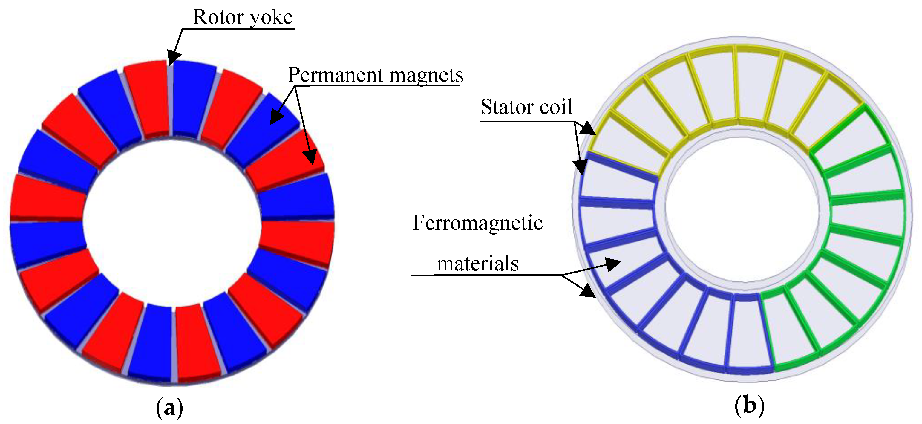
The dynamic performance analysis and optimal design of stator coreless AFPMSG requires an overall study on the structure and basic electromagnetic relationship, as well as the dynamic analytical model. Hence, it is important to introduce the stator coreless AFPMSG and dynamic analytical model in detail.

2.1. AFPMSG

The AFPMSG proposed in this paper is an axial flux permanent magnetic machine topology with two outer rotors and an inner coreless stator. Sectorial PMs that are mounted on the surface of two rotor yokes make up the rotor while the stator armature is formed by epoxy-resin-casted non-overlapping concentrated winding. The configuration and simulation model schematic, as well as the specifications referring to the real AFPMSG, are given in Figure 1 and Table 1. Figure 2 illustrates the rotor and stator winding in detail.
When compared to other topologies, the stator coreless AFPMSG can make full use of the low-grade energy for its low detent torque and stable operation characteristic in the low speed condition. Due to the high moment of inertia contributed by the structure, the generator can also be used as energy storage to absorb the input disturbance energy, which increases system’s anti-disturbance capacity and reliability. Electromagnetic relation is the basis of motor analysis and research. The basic electromagnetic relations of AFPMSG are the steady state equations and main sizing equations [3], as shown below. Equations (1), (2), and (4) indicate the relation between the EMF (electromotive force), electromagnetic torque, electromagnetic power and structural parameters. Equation (3) represents the influence of electrical parameters established by structural parameters on the operation state. From the electromagnetic relation, the transformation principle inside the generator can be known. It can be seen that the steady state equations and main sizing equations represent the operation characteristic under different conditions and the relationship between the rated design power and structure dimensions, respectively. Also, it is obvious that the structure and dimensions have great influence on the output performance of the generator:
E f = 2 π p N 1 k w 1 ϕ f n s = K E n s
T = m 1 2 p N 1 k w 1 ϕ f I a = K T I a
E f = U + I a R 1 + j I a d X s d + j I a q X s q
P e = 2 π 3 32 n s k w A a v α i B δ D o u t 3 ( 1 + k d ) ( 1 k d 2 ) η cos φ
where Xad and Xaq are armature reaction reactance, R1, X1, Ef and Ia are the stator winding impedance, leakage reactance, induced voltage and effective phase current. U is the terminal voltage. ns, kw, Aav, α1, Bδ, Dout and kd are the rotational speed, winding factor, average electrical load, magnet width to pole pitch ratio, flux density of the air gap, outer diameter, and radio of outer diameter to inner diameter of the generator, respectively.

2.2. Dynamic Analytical Model

The direct driven variable speed generation system under consideration consists of stator coreless AFPMSG that is directly coupled to the energy harvest device without any gear box via a simple shaft. Therefore, to find out the dynamic response under the disturbance input and the key parameters that affect the performance, the dynamic analytical model including the swing equation and dynamic model of stator coreless AFPMSG is presented below.

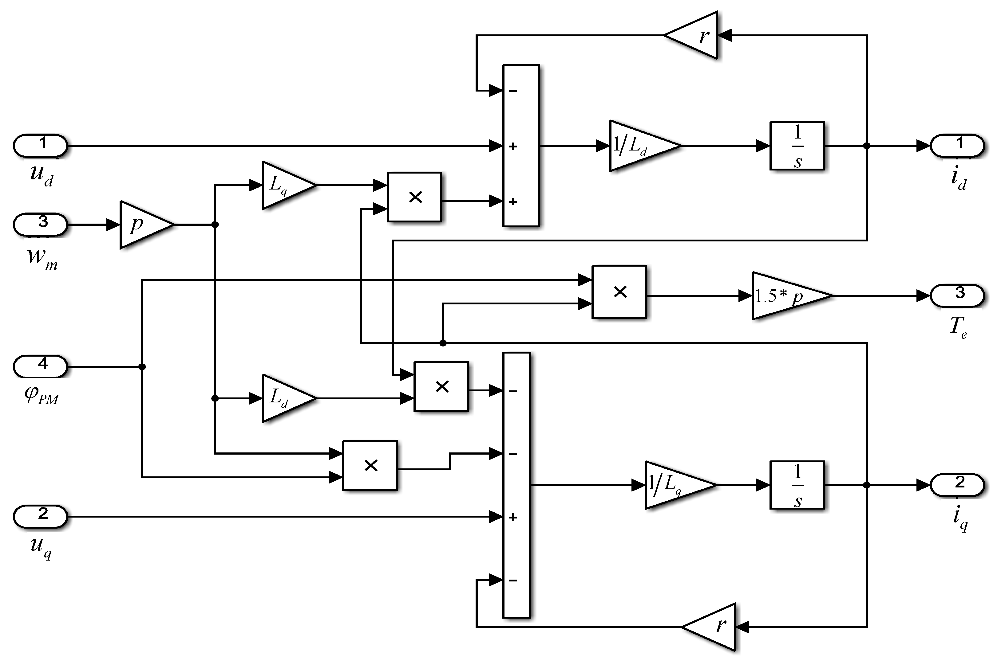
2.2.1. Dynamic Model of AFPMSG

The dynamic model of AFPMSG is derived from the dual-reaction principle of permanent magnet synchronous machine based on d-q rotating reference frame [28,29]. According to the needs of practical application, when considering the conditions and assumptions, such as no loss, torque pulsation, unsaturated magnetic circuit and ignoring the complex magnetic field effects, the second order reduced model is adopted for dynamic study [30,31,32] and the dynamic equations of output voltage are given by:
u d = r i d + d φ d d t w e φ q
u q = r i q + d φ q d t + w e φ d
Considering the influence of stator current, the flux linkage equations are given by:
φ d = L d i d + φ P M      φ q = L q i q
where r is the stator resistance, we is the angular electrical speed, ud, id, uq and iq are the d and q axes stator voltage and current, respectively, ϕd, Ld, ϕq, and Lq are the inductances and flux linkages along d and q axes, and ϕPM is the permanent magnet flux linkage given by φ P M = K e 2 π p , where Ke is the induced EMF constant of AFPMSG.
Dynamic voltage equations can be derived from the above four equations. Figure 3 shows the equivalent circuit diagram of AFPMSG.
u d = r i d L d d i d d t + w e L q i q
u q = r i q L q d i q d t w e L d i d + w e φ P M
The equivalent circuit of AFPMSG can not only be used in steady state analysis but it is also suitable for the transient process. The electromagnetic power generated by AFPMSG can be obtained as below:
P e = 3 2 ( e d i d + e q i q )
where u d , u q are the d and q axes stator voltage and current, respectively, e d = w e L q i q and e q = w e L d i d + w e φ P M . The transient power and torque developed is given by:
P e = 3 2 w e [ φ P M i q ( L d L q ) i d i q ]
T e = P e w m = 3 2 p [ φ P M i q ( L d L q ) i d i q ]
where w m is the mechanical speed, p is the number of pole pairs. In (12), the first part is torque component of PM, which is linearly related to stator current, the second part is the magnetic resistance torque component. For surface mounted AFPMSG, there is Ld = Lq. Therefore, the torque is linear to i q and T e can be modified:
T e = 3 2 p φ P M i q
Based on the modeling equations above, the MATLAB/Simulink model of AFPMSG is shown in Figure 4. The model in Figure 4 contains all of the main parameters that are needed for dynamic performance. From the model, it is obvious that the dynamic performance can be simulated with different input conditions and it can be improved by choosing the proper generator parameters.

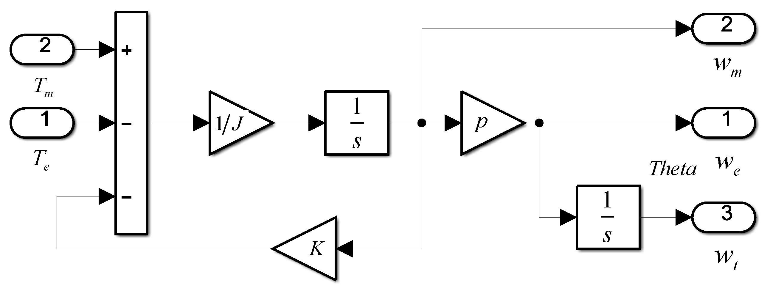
2.2.2. AFPMSG Swing Equation

The swing equation, which is also called the rotational inertia equation [33,34], representing the connection relationship between the energy harvesting device and AFPMSG, is essential for the dynamic performance analysis. The swing equation characterizes the rotor balance relation of the generator between electromagnetic torque and mechanical torque. In a direct driven generation system, the generator is connected to the energy harvesting device through a shaft without any gear box and therefore a simple lumped mass model has been adopted and the differential equation is defined by:
J d w m d t = T m T e K w m
where J is the moment of inertia of rotor mass, Tm and Te are developed by the energy harvesting device and generator, and K is the friction coefficient. The moment of inertia mainly comes from permanent and rotor yoke, and the equation is given by:
J = J s h a f t + J F e + J P M = J s h a f t + D o u t 2 + D i n 2 8 ( m F e + m P M )
m P M = 2 α p π ( D o u t 2 D i n 2 ) 4 h M   m F e = 2 π ( D o u t 2 D i n 2 ) 4 Δ
where J s h a f t is the moment of inertia developed by the shaft, m F e and m P M are the mass of rotor yoke and PM, and h M , Δ are the thickness of PM and rotor yoke.
The MATLAB/Simulation model of the AFPMSG swing equation is shown in Figure 5.

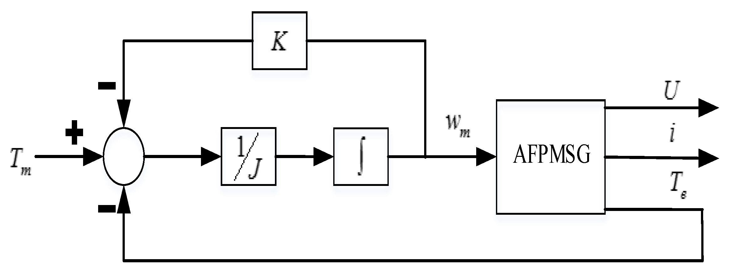
2.2.3. Dynamic Analytical Model of AFPMSG

The dynamic analytical model of AFPMSG combines the dynamic model of APMSG and swing equation, as illustrated in Figure 6. Structure parameters, electrical parameters, torque and movement analysis have been considered in the analytical model. The dynamic response of AFPMSG to the direct driven variable speed condition can be obtained by adjusting the input condition and the generator parameters. Three steps are taken to analyze the dynamic performance of AFPMSG. First, the dynamic response of the generator under different input conditions is found by changing the input torque or speed condition according to the typical input disturbance. Second, the control variable method is applied to change one parameter, while the others are kept unchanged to find the sensitivity of the main parameters of AFPMSG to the performance. The last step is to adjust the generator parameters on the basis of optimization to improve the dynamic performance.

3. Dynamic Performance and Key Factor Analysis

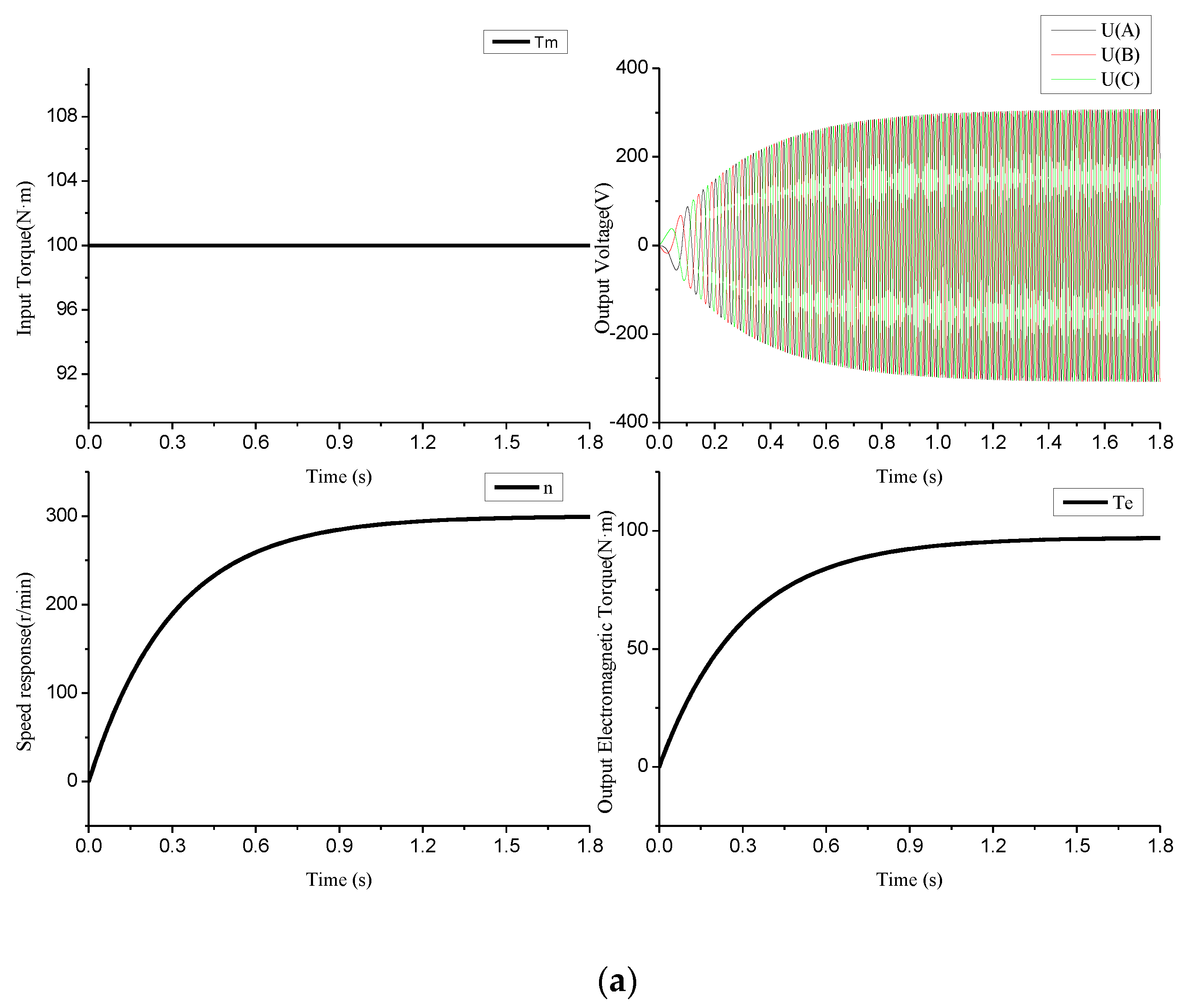
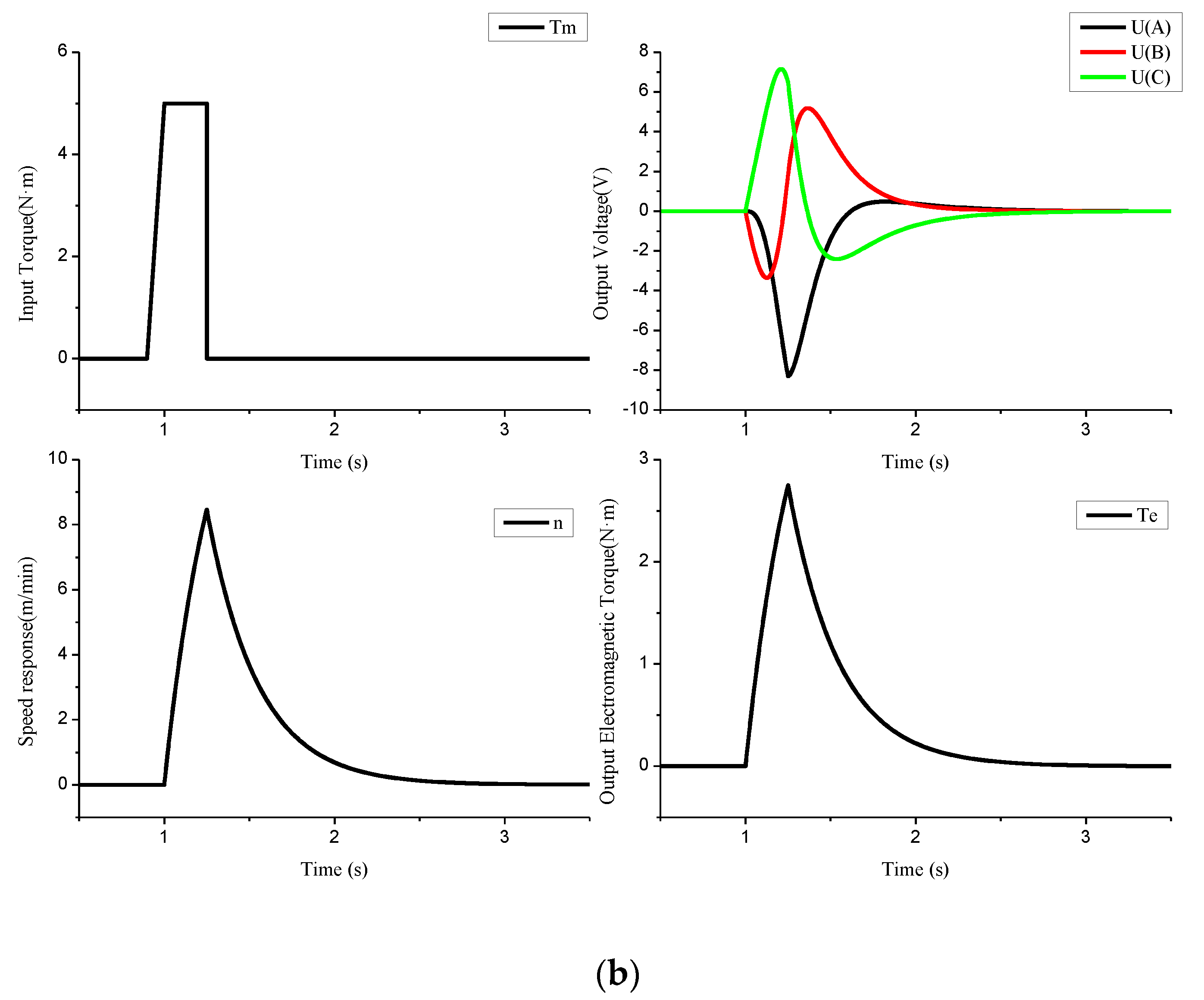
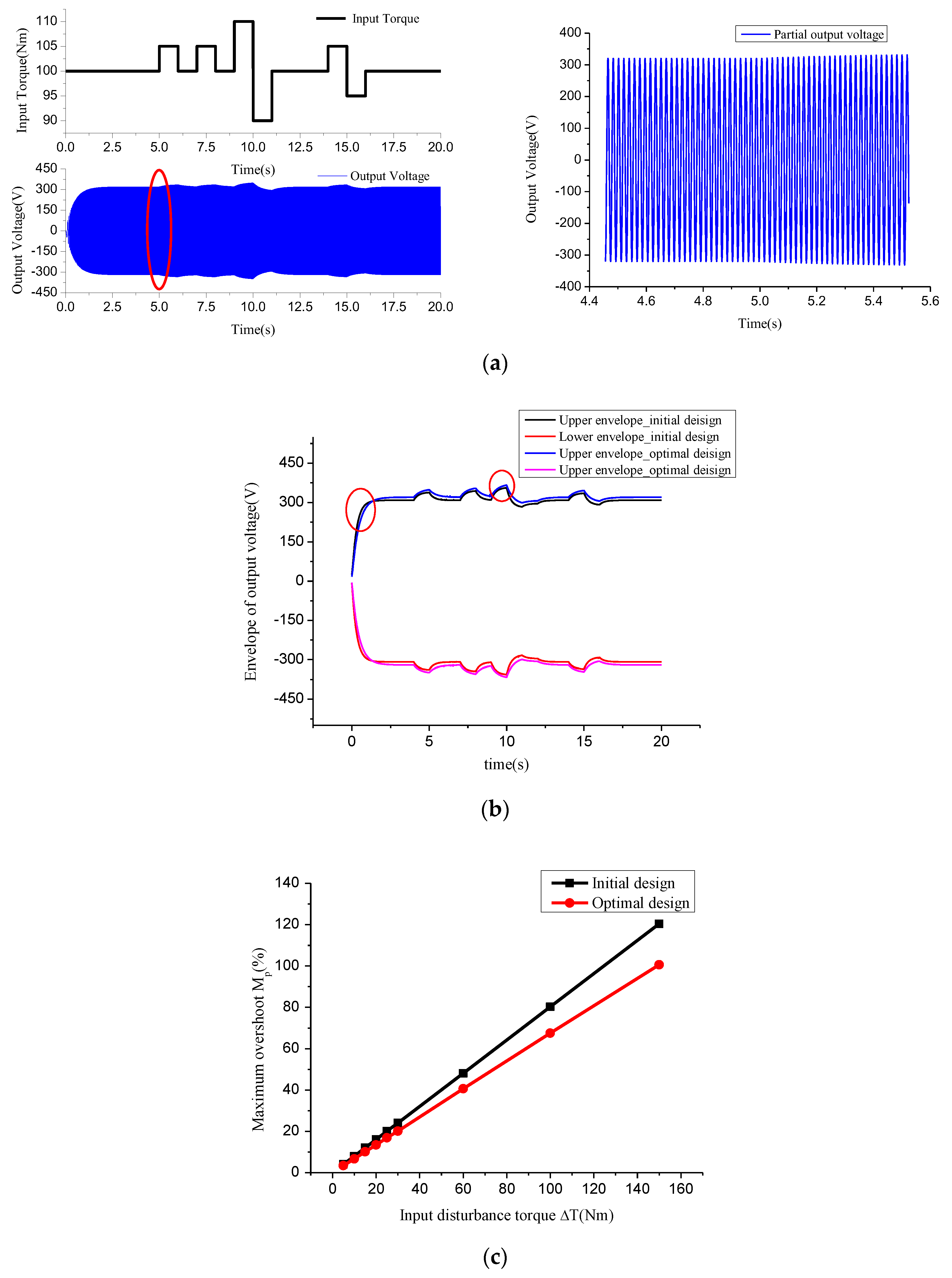
3.1. Dynamic Performance Analysis

In the direct driven generation system without any speed adjustment gear, the energy including the fluctuation and disturbance received by the generator, will directly reflect in the output performance, which depends on the structure parameters of generator. In this paper, dynamic performance analysis is researched via the starting process and response of the output voltage when there is disturbance. According to Table 1, the moment of inertia of stator coreless AFPMSG is 0.957 kgm2, the friction coefficient is 0.09, stator resistant is 3.3 Ω , and induction is Ld = Lq = 0.008 H. Those parameter data are obtained from theory calculation and the simulation of Maxwell ANSOFT.
Figure 7 shows the output voltage curves of the starting up with 100 Nm rated input torque (a) and voltage response to the disturbance with 5 Nm step torque input (b). It can be observed that the generator needs to take some time Δ t (about 1.5 s) to reach the steady state operation or settle down from the disturbance. Besides, the voltage response to the disturbance input is damped oscillation, peak value of which greatly influences the power quality and reliability operation. The output voltage fluctuation caused by unstable input needs to be considered particularly in a direct driven generation system with no speed adjustment gear. Therefore, according to the curves and the principle of the control system [35,36], the regulating time Δ t and maximum voltage overshoot Mp representing the dynamic stable time and the disturbance deviation of the system, respectively, is presented to illustrate the dynamic performance of AFPMSG. The maximum voltage overshoot Mp is defined by:
M p = | U U s | max U s
where U is the transient output voltage, US is the rated steady state voltage value and | U U s | max is the maximum difference between the transient output voltage and the rated steady state voltage.
According to the dynamic analytical model, the rotational inertia J, EMF factor Ke, number of pole pairs N, stator winding resistance r, inductance is Ld, Lq and damping coefficient K are the main model variables that affect the dynamic performance of AFPMSG. The damping coefficient is obtained from the experience formula and it is not a designable parameter of the generator, which is neglected during the optimization. The variables of the AFPMSG analytical model are structure parameters or developed by them, while one structure parameter might affect more than one model variable, as in the relation presented in Section 2. Therefore, it is essential to find out the impact of structure parameters on the dynamic performance to optimize the overall structure of AFPMSG for improving the output dynamic performance, which is the main target of this paper.

3.2. Key Parameter Analysis

The generator structure parameters can be divided into two types according to the dynamic analytical model and structure schematic as shown in Figure 1 and Figure 2. The first type are structure size parameters, which mainly include the outer diameter of the generator, ratio of outer diameter to inner diameter, thickness of PM and rotor yoke, and the length of air gap. The other type is the number parameter of the structure components such as the number of pole pairs and winding turns. Some generator structure parameters are determined by the rated design parameters of AFPMSG or they are limited by the overall structure size, which are not considered in the parameter analysis. Main structure parameters are analyzed by simulation based on the structure and electromagnetic relationship of the AFPMSG in the following.

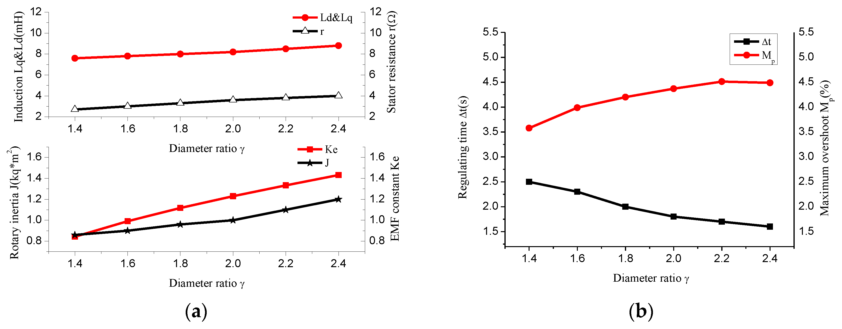
3.2.1. Ratio of Main Dimensions

The ratio of the main dimensions is defined as the ratio of the shaft length to the outer diameter [37], while means the ratio of the outer diameter to the inner diameter in AFPMSG. The ratio is the vital geometry parameter of motor design, which not only decides the diameter of the generator but also affects the variables of the dynamic analytical model, including the rotational inertia, EMF factor, resistance and inductance. The influence of the ratio on the variables and dynamic performance is simulated via parameterization, as shown in Figure 8. The value of all dynamic analytical model variables increase as the ratio increases. The change of EMF factor that is caused by the ratio is greater than other variables, resulting in the output dynamic performance. The maximum output voltage overshoot increases while the regulating time decreases with the effect of changing variable value caused by the adjustment of the main dimension ratio.

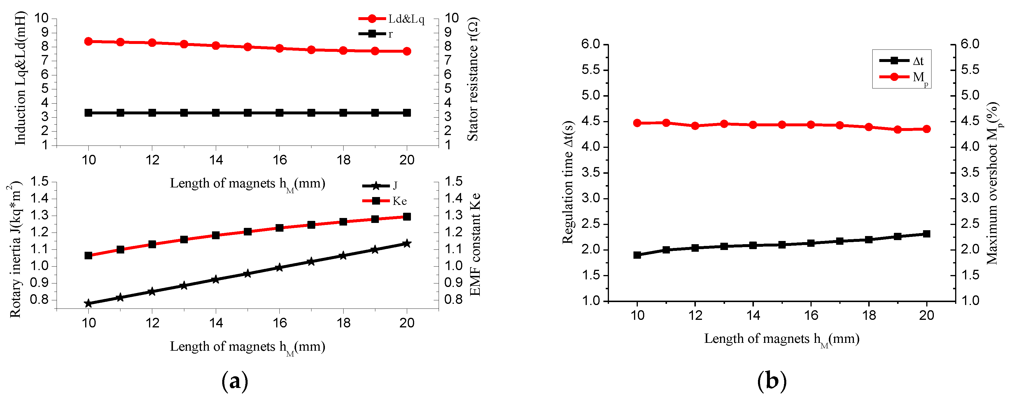
3.2.2. Thickness of the Permanent Magnet

The permanent magnet (PM) is the source of the magnetic field and it is also a part of the magnetic circuit. The electrical time constant as well as the EMF factor and inductance is affected due to the magnetic resistance being closed to air. The EMF factor and rotational inertia increases while the induction decreases when the PM becomes thicker. The dynamic performance changes because of the increasing thickness of the PM with the maximum output voltage overshoot decreasing slightly and the regulating time reducing. When considering the cost and saturation of the magnetic circuit, the thickness of the PM needs to be set properly to achieve the desirable output design and dynamic performance. Figure 9 illustrates the influence on the generator caused by the thickness of PM.

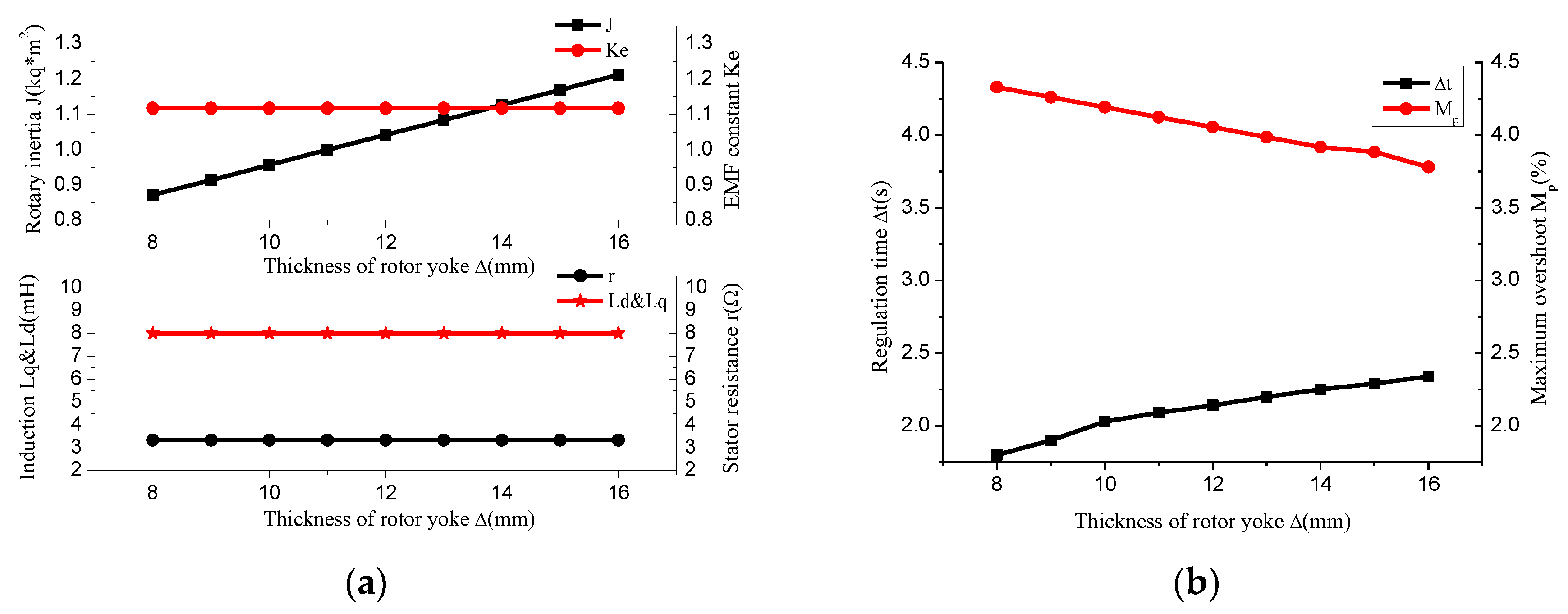
3.2.3. Thickness of Rotor Yoke

The rotor yoke is a component of the magnetic circuit as well as the supporting structure of the PM. Therefore when deciding the value of PM thickness, the saturation of the magnetic circuit and no deformation of the structure need to be taken into account. With electrical and structural demands satisfied, an increment in the thickness of the rotor magnetic yoke causes no impact on the EMF factor, synchronous inductance or stator resistance, but it increases the rotational inertia effectively, which lowers the maximum output voltage overshoot and increases the regulation time, as indicated in Figure 10.

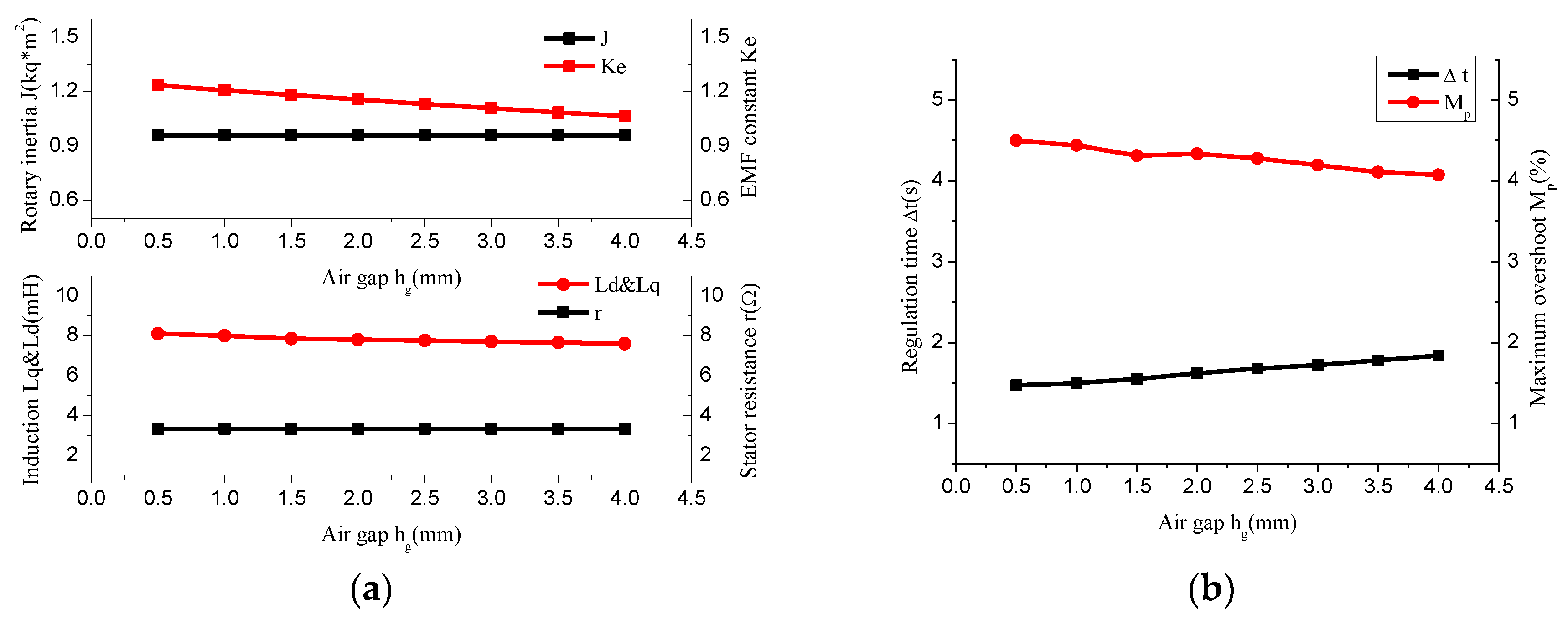
3.2.4. Length of the Air Gap

The length of the air gap is a key factor influencing the EMF factor and the inductance of AFPMSG. Generally, the air gap length of PM motors is larger than that of the rotary motors and the value is usually over 1 mm. The EMF factor and inductance decreases as the air gap increases while the former dropped more significantly, resulting in the regulating time increasing and the maximum voltage overshoot decreasing, as shown in Figure 11.

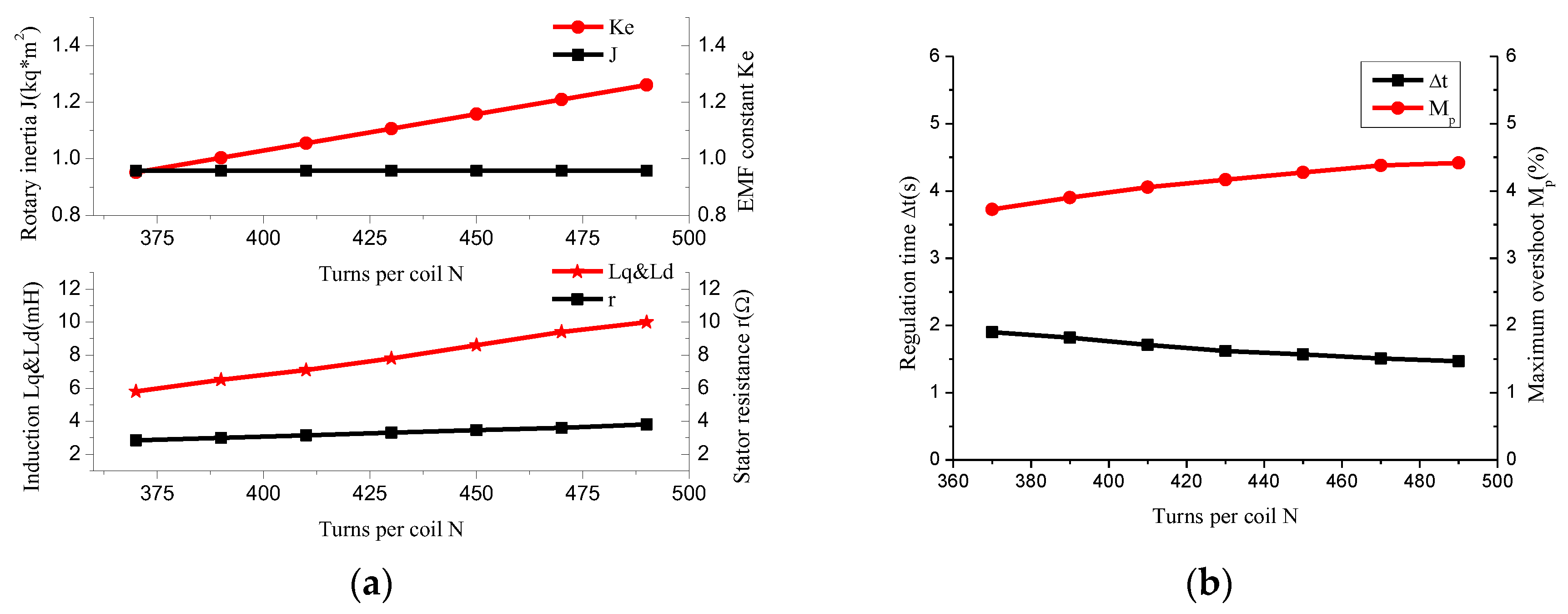
3.2.5. Turns of Coil

The stator of the proposed stator coreless AFPMSG is post winding coils that are cast in epoxy resin or other nonmagnetic materials. The coil turns are greatly dependent on design needs, winding configuration and stator space. However, the turns are also related to the EMF factor, stator resistance and inductance, which affect the output electrical and dynamic performance. The turns demonstrated a positive proportional relation with the EMF factor, with the results demonstrating that the larger the number of turns, the higher the EMF factor will be with the increasing of resistance and induction at the same time. The maximum voltage overshoot increases and the regulating time decreases for an increasing number of coil turns. The dynamic response is shown in Figure 12.

4. Integrated Optimization Design

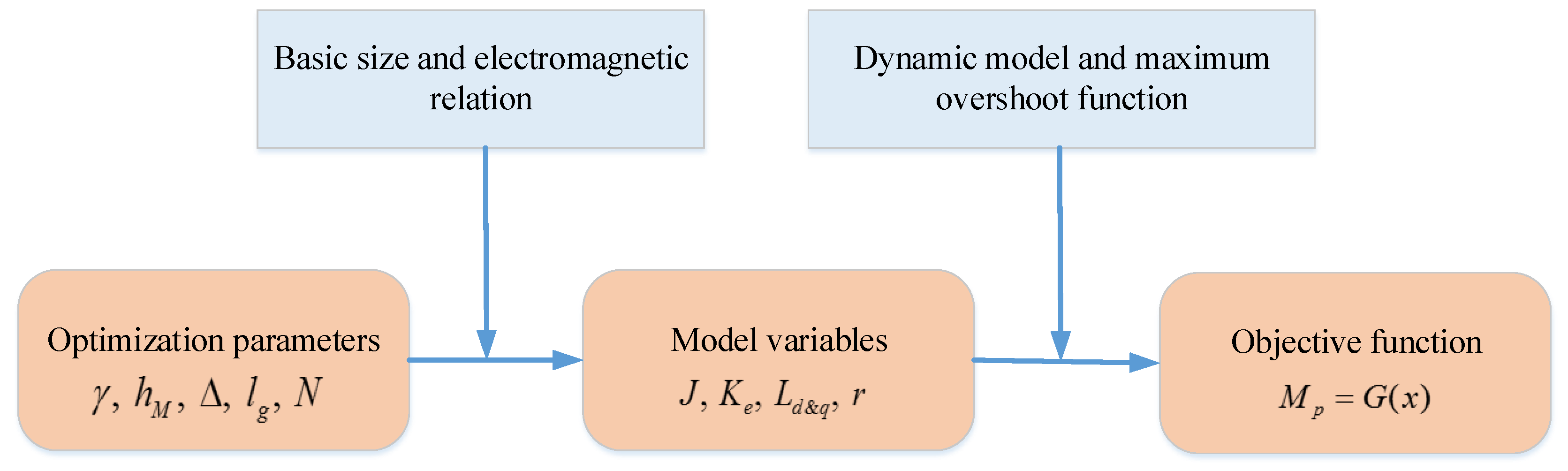
4.1. Optimization Model

As discussed previously, the dynamic response of AFPMSG varies with different structure parameters, and the two dynamic performance indicators that regulate time and maximum output voltage overshoot are affected. In terms of the cross impact of different structure parameters, optimization once at a time or simple superposition optimization is not enough to achieve the optimal target. When optimizing the dynamic performance of AFPMSG, the integrated optimization is essential when taking all of the structure parameters into account. The mathematic equation connecting the dynamic performance indicator and the structure parameters of AFPMSG is given by:
G ( x 1 , x 2 x n ) = M p + k Δ t
where x 1 , x 2 x n are variables of the structure parameters, M p and Δ t are the two dynamic performance indicators of overshoot and regulation time respectively, and k is the weighting coefficient depending on the optimization target. In a direct driven generation system, the dynamic performance is especially concerned because the unstable output voltage amplitude has a direct impact on the safety and reliability operation of the generator with the disturbance conditions. Thus, to reduce the amplitude of the dynamic output voltage, an integrated optimization model aiming at the maximum voltage overshoot is proposed with taking the structure parameters as variables.
Two steps are taken to determine the objective function. The first is to develop the variables of the dynamic analytical model from the generator structure parameters via the calculation of the electromagnetic relationship and the basic size equation. Then the object function is constructed by the variables through the dynamic analytical model and equation of maximum output voltage overshoot. The process of determining the object function is illustrated in Figure 13.
The accurate definition of the constraints in terms of optimization variables is a key step in the optimal design procedure of stator coreless AFPMSG. The optimization in the paper is to improve the dynamic performance on the condition of keeping the output power and the overall size of the generator unchanged. Hence constraints containing the overall size of the generator, the demand of non-saturation of magnetic circuit, and electrical output performance are considered in the optimization. The mathematic optimization model of maximum output voltage overshoot is presented as follows:
{ min M P : M p = G ( γ , h M , Δ , l g , N ) s . t .          P o u t P 0 η η 0 B y o k e B m y o k e s i z e ( D o u t ; l )
where γ ,   h M ,   Δ ,   l g ,   N are the ratio of the outer diameter to inner diameter, thickness of PM, thickness of rotor yoke, length of air gap and turns of coils. P o u t , η and P 0 , η 0 are the power and efficiency of the generator before and after optimization, B y o k e is the flux density of the rotor yoke, which should be smaller than the saturated maximum flux of the rotor yoke B m y o k e , and the overall size of the generator mainly refers to the diameter and axial length. In addition to the limit of output power and efficiency, the rated design parameters are considered as the limitation, such as the rated output voltage and frequency.

4.2. Optimization Design

The dynamic performance optimization design of the stator coreless AFPMSG is the nonlinear multi parameters optimization according to the previous model and analysis, where the algorithm adopted is important to the optimization results and efficiency. Direct search and random search are the two main nonlinear optimization algorithms [38]. Nowadays heuristic optimization algorithms including the genetic algorithm (GA) and Simulated Annealing (SA), have been widely developed and used in the optimization of electrical machines to overcome the limitations of initial conditions, local optimization, the difficulty of considering multi parameters as well as other deficiencies. The GA is a metaheuristic inspired by the process of natural selection that belongs to the larger class of evolutionary algorithms (EA). GA are commonly used to generate high-quality solutions to optimization and search problems by relying on bio-inspired operators such as mutation, crossover and selection [39]. GA has been applied to the optimization design due to the advantages of simple process, global searching ability, and high expansibility, as in [18,19]. In this paper, the improved GA is used to perform the optimization, as discussed in [40].
In terms of the calculation of an integrated optimization model for dynamic performance, the modified design procedure combing the GA is proposed. GA was adopted in the paper to perform the calculation as a part of design procedure for the best optimization result. Thus simple and utility algorithm is preference. To avoid the problems of slow convergence and “precocity”, adjustable crossover probability and mutation probability are used in the GA process. Figure 14 illustrates the basic structure of the modified design procedure. A preliminary design is obtained through the sizing equation and basic electromagnetic relation on the condition of rated design parameters. The main structure parameters are optimized by the GA applied to search for the best solution from the variables of the generator for the object function.
The optimization design is carried out by MATLAB GA tools that are based on the mathematic optimization model. The structure parameters before and after the optimization for maximum output voltage overshoot target are given in Table 2. When comparing the data of Table 2, the structure parameters of the generator are optimized with minor adjustments to the overall diameter and axial length. The turns of coils and thickness of PM are decreased after optimization, which will reduce the EMF factor and loss of the generator as well as the flux density of the air gap and output power. On the contrary, the decreasing of the diameter ratio and length of the air gap can not only make up the influence mentioned above but also reduce the dynamic output voltage overshoot. Besides, although the mass of generator increases, the increasing of the rotor yoke thickness without changing the whole size greatly increases the rotational inertia and lowers the output voltage overshoot because the increment of mass concentrates on the rotor.

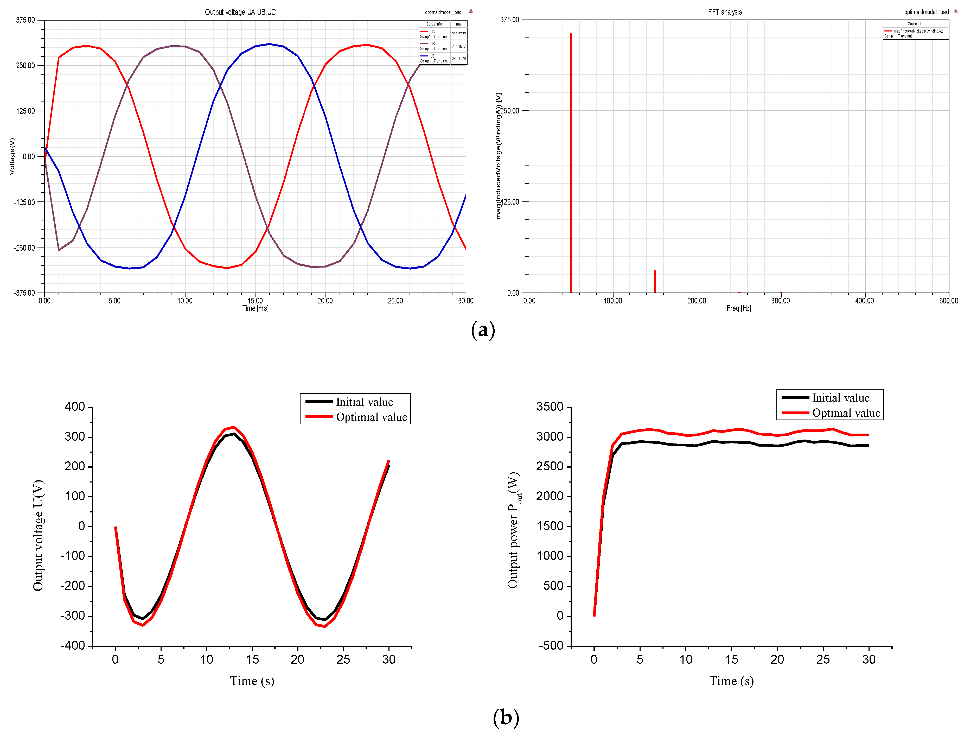
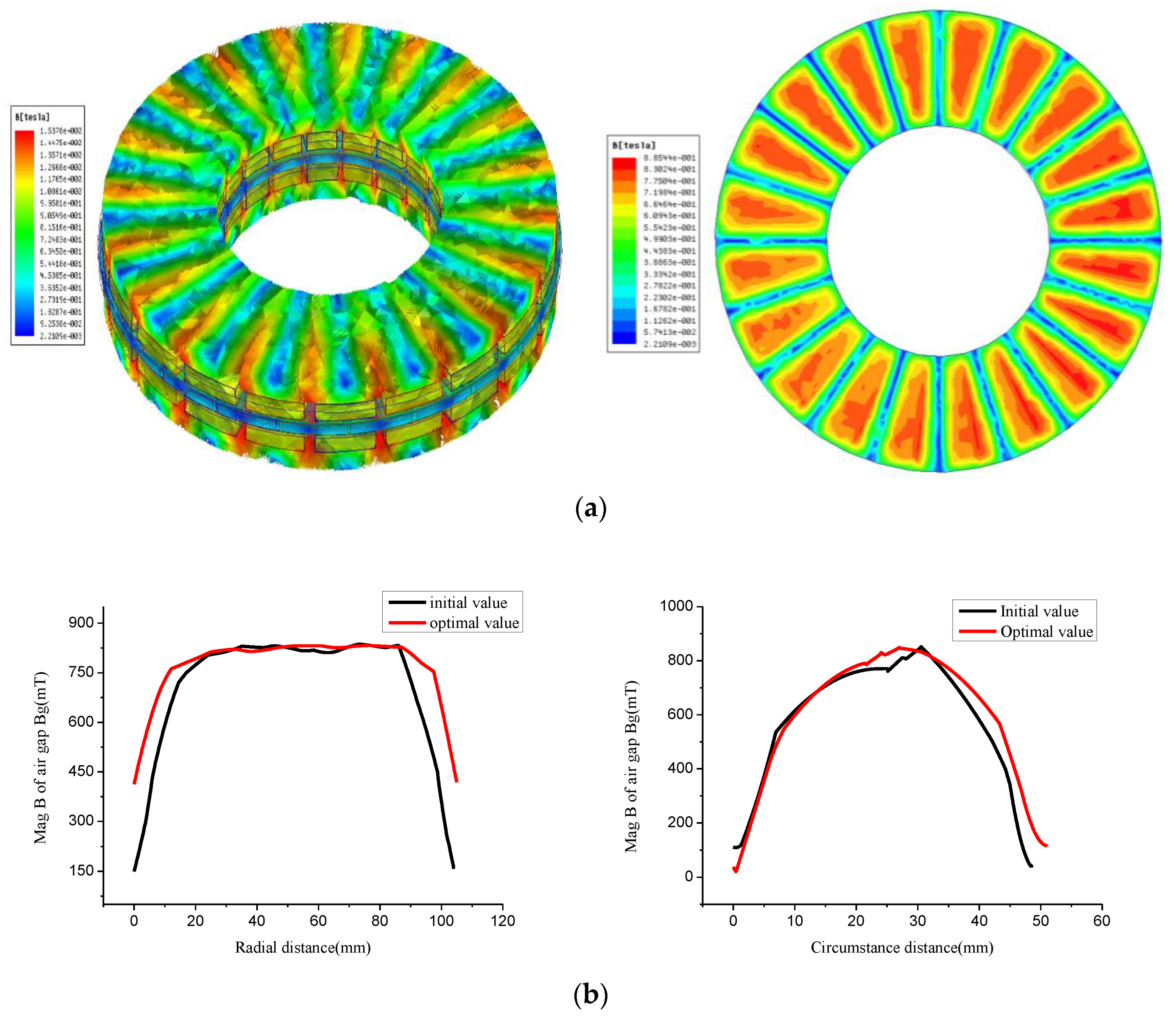
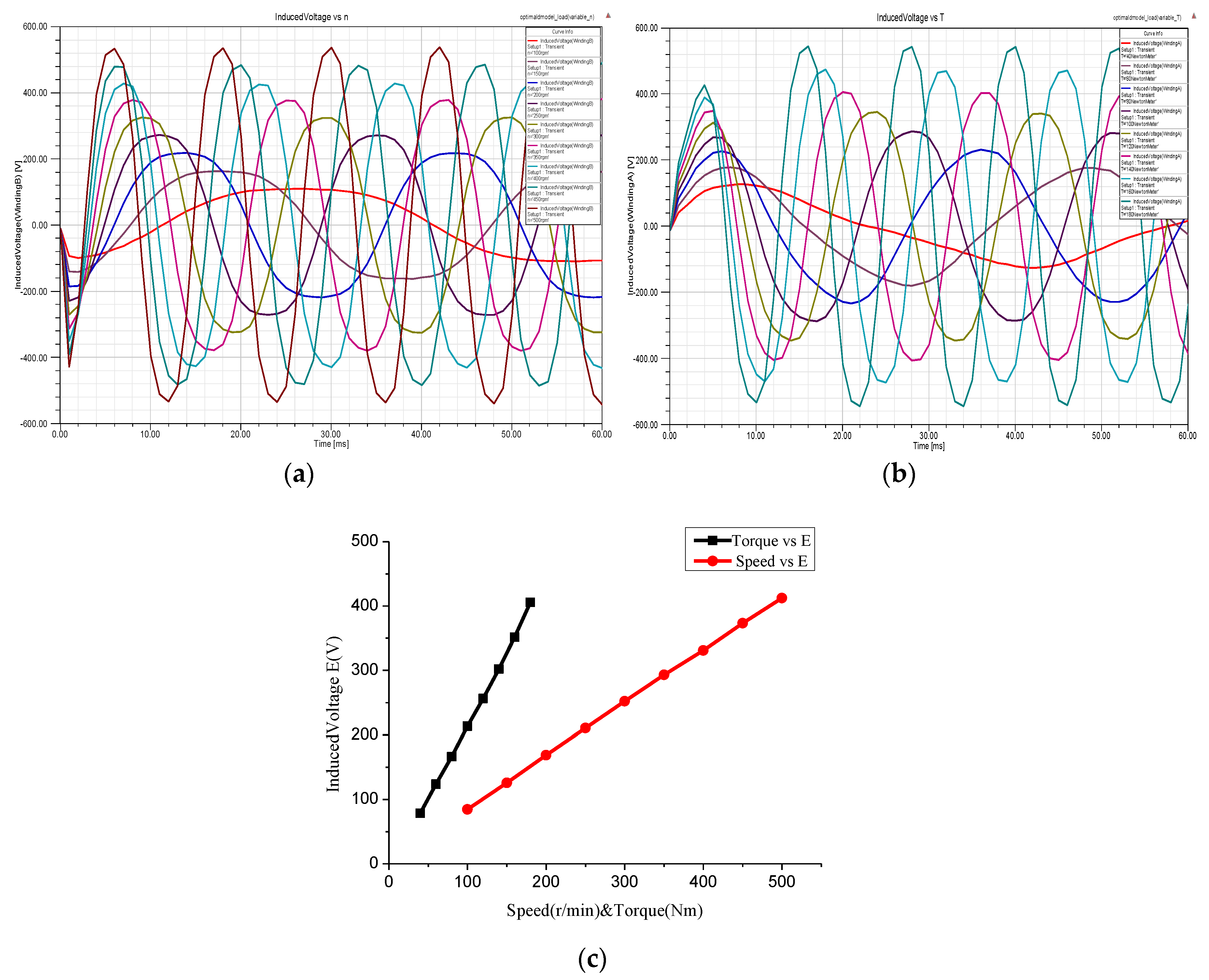
5. 3D Finite Element Analysis

3D finite element analysis is performed to evaluate the validity of the dynamic analytical model and the optimization design procedure presented in the previous sections. The 3D model of the stator coreless AFPMSG is developed and simulated via the electromagnetic field simulation software Maxwell ANSOFT (Maxwell v16, ANSYS, Inc., Pittsburgh, PA, USA).
The finite element models of the proposed AFPMSG are based on Table 2. Figure 15a illustrates the magnetic field distribution for the whole AFPMSG and the effective plane of the air gap. Asymmetrical distribution of flux density in the rotor yoke is caused by the armature reaction when considering the influence of stator current. As mentioned in Section 4, the optimization design of generator dynamic performance with the consideration of rotational inertia will increase the thickness of rotor yoke, which results in lower values of the maximum flux density being presented in the rotor yoke. Along with the structure characteristic of the stator coreless, it is obvious that the magnetic circuit is not saturated. The flux density of air gap increases with the optimization of air gap length and the thickness of PM, which guarantees the demand of electrical output. The flux density distributions of the air gap along the radial and axial direction are given in Figure 15b.
The optimal three phase voltage as well as their harmonic contents are obtained and shown in Figure 16a. It is obvious that the optimized generator has a sinusoidal output voltage with the value meeting the design requirements and the harmonic contents can be negligible.
Figure 16b compares the output voltage and power before and after optimization. The output voltage and power of optimization are bigger than that before optimization, indicating that the improved structure parameters enhance the electrical performance. The comparison also confirms the validity of structure parameter optimization for electrical performance.
To compare the dynamic performance, the output voltage response to the same continuous disturbance torque input is simulated and analyzed before and after the optimization of the AFPMSG. The output voltages before and after the optimization are shown in Figure 17a, while Figure 17b illustrates the envelop curve of the maximum output voltage. The output voltage response of the optimized generator is slower and smaller than the preliminary one. It is observed that the dynamic response of output voltage after optimization became more stable, which exerts a better inhibition of voltage leap in the case of heavy disturbance. The comparison of maximum output voltage overshoot with different input torques is indicated in Figure 17c. The markings in Figure 17b,c indicate that the output voltage becomes more stable and the maximum output voltage overshoot is reduced, making the system more safe and reliable after optimization. Moreover, the inhibition of voltage leap for the optimized generator is more apparent when the input is heavily disturbed. It is concluded are obtained that the dynamic performance of the optimized AFPMSG is better and the optimized AFPMSG can operate more stably and reliable with unstably input conditions.
The comparisons between the preliminary design and optimal design are given in Table 3, where the items to be compared are mainly the output electrical output performance, consumption of PM, and the dynamic performance. It is obvious that the optimized generator complies with design requirements with slight improvement in terms of economy and efficiency. Besides, the output peak voltage is reduced under the same disturbance condition, which improves the safety and reliability of the generator.
Additional simulation is carried out on the output voltage versus rotor speed and input torque for a constant resistive load, as shown in Figure 18. The result shows that the voltage versus rotor speed and input torque appear to be a linear relationship respectively, even in the low speed range, making it suitable for direct driven power generation such as direct couple wave power generation and low speed wind turbines.

6. Conclusions

In this paper, a dynamic performance study and an optimization design of stator coreless AFPMSG was presented for direct driven variable speed power generation application. The dynamic analytical model was developed based on the structure analysis and a dynamic model of AFPMSG and swing equation. Moreover, dynamic performance indexes were considered through the simulation of a dynamic analytical model under starting up and disturbance input conditions. Key structure parameters were analyzed based on the dynamic analytical model and an integrated optimization model with multiple structure parameter variables was developed for the optimization design of the generator dynamic performance.
Considering the demand of dynamic performance for direct driven generators, based on a nonlinear iterative genetic algorithm, a modified optimization design procedure was proposed. A 3 kW 300 r/min stator coreless AFPMSG was optimally designed through the design procedure. Theoretical calculation and simulation analysis were performed on the electrical and dynamic performance of the generator before and after optimization, the results of which showed that the dynamic performance was improved after optimization without reducing the electrical output. Moreover, the 3D finite element simulation outcomes and comparison also demonstrated the accuracy of the theoretical analysis and model in the paper.

Author Contributions

W.W. (Wenqiang Wang) and Y.W. designed the main parts of the research, including objective function establishment and optimal methodology designing. W.W. (Weijun Wang) was responsible for guidance, a number of key suggestions and manuscript editing. L.M. and H.M. mainly contributed to the writing of the paper and were also responsible for project administration. H.L. and G.Z. made contributions to simulations in Ansoft and gave the final approval of the version to be published.

Funding

This research received no external funding.

Acknowledgments

The authors would like to acknowledge the technological and financial support from “The National Science and Technology Support Program (supported by the Ministry of Science and Technology of P.R.C. No. 2014BAC01B05)”, “Key projects of PLA (BY113C001)”, “Army Funding for military graduate students (2016JY486”. The authors are grateful for the comments and suggestions provided by the anonymous reviewers and editor helped to improve the quality of the paper

Conflicts of Interest

The authors declare no conflict of interest.

References

  1. Lampola, P. Directly Driven, Low-Speed Permanent-Magnet Generators for Wind Power Applications; Helsinki University of Technology: Espoo, Finland, 2000. [Google Scholar]
  2. Chan, T.F.; Lai, L.L. An Axial-Flux Permanent-Magnet synchronous generator for a Direct-Coupled Wind-Turbine system. IEEE Trans. Energy Convers. 2007, 22, 86–94. [Google Scholar] [CrossRef]
  3. Gieras, J.F.; Wing, M. Permanent Magnet Motor Technology: Design and Applications; Marcel Dekker: New York, NY, USA, 2009. [Google Scholar]
  4. Gieras, J.F.; Wang, R.J.; Kamper, M.J. Axial FLUX Permanent Magnet Brushless Machines; Springer: Dordrecht, The Netherlands, 2005. [Google Scholar]
  5. Capponi, F.G.; Donato, G.D.; Caricchi, F. Recent advances in Axial-Flux Permanent-Magnet machine technology. IEEE Trans. Ind. Appl. 2012, 48, 2190–2205. [Google Scholar] [CrossRef]
  6. Kamper, M.J.; Wang, R.J.; Rossouw, F.G. Analysis and performance evaluation of axial FLUX Air-Cored stator permanent magnet machine with concentrated coils. In Proceedings of the IEEE International Electric Machines & Drives Conference, Antalya, Turkey, 3–5 May 2007; pp. 13–20. [Google Scholar]
  7. Kamper, M.J.; Wang, R.J.; Rossouw, F.G. Analysis and performance of axial FLUX Permanent-Magnet machine with Air-Cored nonoverlapping concentrated stator windings. IEEE Trans. Ind. Appl. 2008, 44, 1495–1504. [Google Scholar] [CrossRef]
  8. Laxminarayan, S.S.; Singh, M.; Saifee, A.H.; Mittal, A. Design, modeling and simulation of variable speed Axial Flux Permanent Magnet Wind Generator. Sustain. Energy Technol. Assess. 2017, 19, 114–124. [Google Scholar] [CrossRef]
  9. Wang, R.J.; Kamper, M.J.; Westhuizen, K.D.; Gieras, J.F. Optimal design of a coreless stator axial flux permanent-magnet generator. IEEE Trans. Magn. 2005, 41, 55–64. [Google Scholar] [CrossRef]
  10. Cavagnino, A.; Lazzari, M.; Profumo, F.; Tenconi, A. A comparison between the axial flux and the radial flux structures for PM synchronous motors. IEEE Trans. Ind. Appl. 2002, 38, 1517–1524. [Google Scholar] [CrossRef]
  11. Park, Y.S.; Koo, M.M.; Jang, S.M.; Choi, J.-Y.; You, D.-J. Performance evaluation of Radial- and Axial-Flux PM wind power generators with mechanical energy storage system. IEEE Trans. Energy Convers. 2015, 30, 237–245. [Google Scholar] [CrossRef]
  12. Sitapati, K.; Krishnan, R. Performance comparisons of radial and axial field, permanent-magnet, brushless machines. IEEE Trans. Industry Appl. 2001, 37, 1219–1226. [Google Scholar] [CrossRef]
  13. Pop, A.A.; Jurca, F.; Oprea, C.; Chirca, M.; Breban, S.; Radulescu, M.M. Axial-flux vs. radial-flux permanent-magnet synchronous generators for micro-wind turbine application. In Proceedings of the European Conference on Power Electronics and Applications, Lille, France, 2–6 September 2013; pp. 1–10. [Google Scholar]
  14. Daghigh, A.; Javadi, H.; Torkaman, H. Design optimization of Direct-Coupled ironless axial FLUX permanent magnet synchronous wind generator with low cost and high annual energy yield. IEEE Trans. Magn. 2016, 52, 1–11. [Google Scholar] [CrossRef]
  15. Zhang, X.W.; Wang, X.Y.; Du, J.; Tang, R. Amelioration of coreless Permanent-Magnet disk synchronous motor based on fem: Motor with wedge airgap. J. Iron Steel Res. Int. 2006, 13, 427–432. [Google Scholar] [CrossRef]
  16. Barba, P.D.; Savini, A.; Wiak, S. Field Models in Electricity and Magnetism; Springer: Dordrecht, The Netherlands, 2008. [Google Scholar]
  17. Barba, P.D. Multiobjective Shape Design in Electricity and Magnetism; Springer: Dordrecht, The Netherlands, 2010. [Google Scholar]
  18. Hawe, G.I.; Sykulski, J.K. A scalarizing One-Stage algorithm for efficient Multi-Objective optimization. IEEE Trans. Magn. 2008, 44, 1094–1097. [Google Scholar] [CrossRef]
  19. Lok, C.L.; Vengadaesvaran, B.; Ramesh, S. Implementation of hybrid pattern search–genetic algorithm into optimizing axial-flux permanent magnet coreless generator (AFPMG). Electr. Eng. 2016, 1–11. [Google Scholar] [CrossRef]
  20. Ahn, Y.; Park, J.; Lee, C.G.; Jeong, Y.-S.; Kim, Y.-J.; Jung, S.-Y. Optimal design of direct-driven PM wind generator using memetic algorithm coupled with FEM. In Proceedings of the International Conference on Electrical Machines and Systems, Tokyo, Japan, 15–18 November 2010; pp. 1–6. [Google Scholar]
  21. Jin, H.L.; Song, J.Y.; Kim, D.W.; Kim, J.-W.; Kim, T.-J.; Jung, S.-Y. Particle swarm optimization algorithm with intelligent particle number control for optimal design of electric machines. IEEE Trans. Ind. Electron. 2017, 65, 1791–1798. [Google Scholar]
  22. Meng, D.W.; Zhou, M.L. The application of Simulated Annealing Algorithm to electric machine design. Electr. Mach. Control 2001, 5, 154–158. [Google Scholar]
  23. Rostami, N.; Feyzi, M.R.; Pyrhonen, J.; Parviainen, A.; Behjat, V. Genetic algorithm approach for improved design of a variable speed Axial-Flux Permanent-Magnet synchronous generator. IEEE Trans. Magn. 2012, 48, 4860–4865. [Google Scholar] [CrossRef]
  24. Mahmoudi, A.; Kahourzade, S.; Rahim, N.A.; Hew, W.P. Design, analysis, and prototyping of an Axial-Flux permanent magnet motor based on genetic algorithm and Finite-Element analysis. IEEE Trans. Magn. 2013, 49, 1479–1492. [Google Scholar] [CrossRef]
  25. Benlamine, R.; Dubas, F.; Randi, S.A.; Lhotellier, D.; Espanet, C. Design by optimization of an axial-flux permanent-magnet synchronous motor using genetic algorithms. In Proceedings of the International Conference on Electrical Machines and Systems, Busan, Korea, 26–29 October 2013; pp. 13–17. [Google Scholar]
  26. Taran, N.; Ardebili, M. A novel approach for efficiency and power density optimization of an Axial Flux Permanent Magnet generator through genetic algorithm and finite element analysis. In Proceedings of the 2014 IEEE 23rd International Symposium on Industrial Electronics, Istanbul, Turkey, 1–4 June 2014; pp. 709–714. [Google Scholar]
  27. Virtič, P.; Vražić, M.; Papa, G. Design of an axial FLUX permanent magnet synchronous machine using analytical method and evolutionary optimization. IEEE Trans. Energy. 2016, 31, 150–158. [Google Scholar] [CrossRef]
  28. Gary, S. Two-reaction theory of synchronous machines. Electr. Eng. 2013, 56, 905–906. [Google Scholar] [CrossRef]
  29. Behjat, V.; Hamrahi, M. Dynamic modeling and performance evaluation of axial flux PMSG based wind turbine system with MPPT control. AIN Shams Eng. J. 2014, 5, 1157–1166. [Google Scholar] [CrossRef]
  30. Bang, D.; Polinder, H.; Shrestha, G.; Ferreira, J.A. Review of generator system for direct- drive wind turbines. In Proceedings of the European Wind Energy Conference & Exhibition, Brussels, Belgium, 31 March–3 April 2008; pp. 1–11. [Google Scholar]
  31. Patil, K.; Mehta, B. Modeling and control of variable speed wind turbine with permanent magnet synchronous generator. In Proceedings of the International Conference on Advances in Green Energy, Thiruvananthapuram, India, 17–18 December 2015; pp. 258–264. [Google Scholar]
  32. Yin, M.; Li, G.; Zhou, M.; Zhao, C. Modeling of the Wind Turbine with a Permanent Magnet Synchronous Generator for Integration. In Proceedings of the Power Engineering Society General Meeting, Tampa, FL, USA, 24–28 June 2007; pp. 1–6. [Google Scholar]
  33. Demello, F.P.; Hannett, L.N. Determination of synchronous machine stability study constants. Final Rep. Power Technol. 1980, 110, 268–280. [Google Scholar]
  34. Cao, X.; Kurita, A.; Mitsuma, H.; Tada, Y.; Okamoto, H. Improvements of numerical stability of electromagnetic transient simulation by use of phase-domain synchronous machine models. Electr. Eng. Jpn. 2015, 128, 53–62. [Google Scholar] [CrossRef]
  35. D’arco, S.; Suul, J.A.; Fosso, O.B. Control system tuning and stability analysis of Virtual Synchronous Machines. In Proceedings of the IEEE Energy Conversion Congress and Exposition, Denver, CO, USA, 15–19 September 2013; pp. 2664–2671. [Google Scholar]
  36. Gao, J.; Wang, X.; Zhang, L. Oscillation, Stability and Excitation Regulation of Synchronous Machine Systems. In AC Machine Systems; Springer: Berlin/Heidelberg, Germany, 2009. [Google Scholar]
  37. Chapman, S.J. Electric Machinery Fundamentals; McGraw-Hill: New York, NY, USA, 2014. [Google Scholar]
  38. Nezhadhosein, S.; Heydari, A.; Ghanbari, R. A modified hybrid genetic algorithm for solving nonlinear optimal control problems. Math. Probl. Eng. 2015, 2015, 1–21. [Google Scholar] [CrossRef]
  39. Mitchell, M. An Introduction to Genetic Algorithms; MIT Press: Cambridge, MA, USA, 1996. [Google Scholar]
  40. You, Y.M.; Hwang, K.Y.; Kwon, B.I. Optimal design of distributed winding axial flux permanent magnet synchronous generator for wind turbine systems. In Proceedings of the Digests of the 2010 14th Biennial IEEE Conference on Electromagnetic Field Computation, Chicago, IL, USA, 9–12 May 2010. [Google Scholar]
Figure 1. Axial flux permanent magnet synchronous generator (AFPMSG) configuration without the stator core and simulation model. (a) Assemble model; (b) Ironless stator structure; (c) simulation model.
Energies 11 03162 g001
Figure 2. Structure of the ironless AFPMSG. (a) Rotor and permanent magnet (PM) structure; (b) Ironless stator structure.
Energies 11 03162 g002
Figure 3. Equivalent circuit. (a) in q axis; (b) in d axis.
Energies 11 03162 g003
Figure 4. Dynamic model of the proposed AFPMSG.
Energies 11 03162 g004
Figure 5. Simulink model of swing function.
Energies 11 03162 g005
Figure 6. Dynamic characteristic analysis block diagram.
Energies 11 03162 g006
Figure 7. Output performance of starting and input disturbance. (a) Start with constant torque input; (b) dynamic performance with step torque input.
Energies 11 03162 g007aEnergies 11 03162 g007b
Figure 8. Influence of different diameter ratio: (a) Model variables; (b) Dynamic characteristic response.
Energies 11 03162 g008
Figure 9. Influence of different PM thickness: (a) Model variables; (b) Dynamic characteristic response.
Energies 11 03162 g009
Figure 10. Influence of rotor yoke thickness: (a) Model variables; (b) Dynamic characteristic response.
Energies 11 03162 g010
Figure 11. Influence of different air gap length: (a) Model variables; (b) Dynamic characteristic response.
Energies 11 03162 g011
Figure 12. Influence of different turns per coil: (a) Model variables; (b) Dynamic characteristic response.
Energies 11 03162 g012
Figure 13. Objective function deriving block diagram.
Energies 11 03162 g013
Figure 14. Flowchart of the genetic algorithm (GA) optimization design procedure.
Energies 11 03162 g014
Figure 15. Distribution and comparison of Mag B before and after optimization: (a) Magnetic flux density distribution in the APFMSG and on the middle plane of the effective air gap; (b) The circumferential distribution curve at average radius and radial distribution curve of Mag B before and after optimization.
Energies 11 03162 g015
Figure 16. Distribution and comparison of output performance: (a) Output voltage after optimization and Fast Fourier Transform (FFT) analysis; (b) Output voltage and power comparison before and after optimization.
Energies 11 03162 g016
Figure 17. Dynamic performance analysis: (a) Output voltage with variable torque input for optimal design and partial detail; (b) Envelop comparison of the maximum output voltage before and after optimization; (c) Maximum overshoot with different input disturbance torque.
Energies 11 03162 g017
Figure 18. Induced Voltage curves with varied speed & torque. (a) simulation curves of induced voltage with varied speed input; (b) simulation curves of induced voltage with varied torque input; (c) comparison on the induced voltage between varied speed and torque input.
Energies 11 03162 g018
Table 1. Design data of the proposed axial flux permanent synchronous generator (AFPMSG).
ParametersValueParametersValue
Rated output power P o u t 3 kWOuter diameter D o u t 0.418 m
Rated RMS voltage at rated 300 rpm: U o u t 220 VOut-in diameter ratio: γ 1.8
Number of phase: m 3Magnet thickness: h M 15 mm
Frequency: f 50 HzWinding turns per phase: N 434
Number of pole pairs: p 10Air gap length: l g 1 mm
Pole-arc coefficient: α 0.8Rotor yoke thickness: Δ 10 mm
Table 2. Design variables of the AFPMSG before and after optimization.
Design VariableInitial ValueOptimal Value
Outer diameter: D o u t 418 mm420 mm
Out-in diameter ratio: γ 1.81.75
Magnet thickness: h M 15 mm13 mm
Winding turns per phase: N 434420
Air gap length: l g 1 mm0.6 mm
Rotor yoke thickness: Δ 10 mm15 mm
Axial length: l 62.1 mm67.5 mm
Table 3. Output and dynamic performances of the AFPMSG before and after optimization.
ParametersInitial ValueOptimal Value
Output performanceRated output power: P o u t 2893 W3078 W
Rated RMS voltage at rated 300 rpm: U o u t 220 V237 V
Total loss: P l o s s 325.8 W298.6 W
Maximum efficiency: η 0.90.912
PM material volume: V P M 0.0024 m30.002 m3
Dynamic performanceRegulating time: Δ t 1.5 s1.9 s
Maximum voltage overshoot: M p 4.45%3.37%

