Article

A Nonlinear Disturbance Observer Based Virtual Negative Inductor Stabilizing Strategy for DC Microgrid with Constant Power Loads

College of Automation, Harbin Engineering University, Harbin 150001, China
*
Author to whom correspondence should be addressed.
Energies 2018, 11(11), 3174; https://doi.org/10.3390/en11113174
Submission received: 16 October 2018 / Revised: 7 November 2018 / Accepted: 13 November 2018 / Published: 15 November 2018

Abstract

:
For the dc microgrid system with constant power loads (CPLs), the dc bus voltage can easily cause high-frequency oscillation owing to the complicated impedance interactions. The large line inductance and the CPL-side capacitance will form an undamped LC circuit on the dc bus, which, together with the CPL, will make the system fall into the negative-damping region, thus causing the system instability. To address this problem, a virtual negative inductor (VNI) is built on the source side converter in this paper, which can effectively counteract the large line inductance, thus alleviating the instability problem. Moreover, a nonlinear disturbance observer (NDO) is proposed for estimating the converter output current, which relieves the strong dependence of the proposed VNI strategy on the output current measurement. And the proposed strategy is implemented in a totally decentralized manner, thus alleviating the single-point-failure problem in the central controller. For assuring the optimal parameter value for the proposed stabilizing strategy, a system root-locus diagram based parameter designing approach is adopted. And comparative Nyquist diagram based stability analyses are taken for studying the robustness of the proposed strategy to the system perturbations. Finally, detailed real-time simulations are conducted for validating the effectiveness of the proposed stabilizing strategy.

1. Introduction

Nowadays, distributed generations (DGs) from renewable sources and energy storage systems are reshaping the structure of the modern power system [1,2]. Due to incremental penetrations of the dc-based renewable sources (PVs, batteries, and supercapacitors) and loads (electric vehicles), the dc microgrid system is gaining people’s increasing attentions. Compared with the traditional ac power system, the newly emerged dc microgrid system has the following advantages: a higher efficiency with less energy conversion stages, an improved reliability with highly flexible structures, and an enhanced controllability with no reactive power regulation or synchronization problem.
From the perspective of the system composition, the dc microgrid system is a typical heterogeneous system with various kinds of active loads [3,4,5,6,7,8]. Due to the high performance of the load converter, the active load may exhibit a constant power load (CPL) characteristics even when the bus voltage fluctuates. It is known that the CPL will introduce a negative incremental resistance to the dc bus, which lowers the system damping effect, thus deteriorating the system stability. The situation would be more serious for the system with a large CPL power, a small source-side capacitance, or a large line inductance [9,10,11,12,13].
Stability is always the thing that matters, which is also the key point that needs specific considerations for the dc microgrid system. For stabilizing the dc microgrid system with CPLs, several stabilizing methods have been proposed. The passive damping method [14] proposes to introduce a physical damper for stabilizing the system, which used to be quite welcome due to its simplicity for implementation. However, additional power loss will be caused by the implemented physical damper, which lowers the system efficiency. The active stabilizing method, on the other way, maintains the system stability from the control point of view [15,16,17,18,19,20,21,22,23,24,25,26,27]. No additional physical damper is required in theses active damping methods, thus alleviating the system efficiency problem. The load-side active damping method [28,29,30,31,32] emerged earlier in history. A dedicated stabilizing power will be injected to the load, which modifies the CPL characteristics, thus solving the instability problem. Obviously, the additional injected power will impact the performance of the CPL, which is not acceptable for the loads with critical dynamic requirements.
The source-side active stabilizing strategy is an expected way for solving this performance compromise problem. The source-side active stabilizing strategy modifies the source dynamics to stabilize the system, without sacrificing the critical load performance. The representatives of the source side stabilizing strategies include the sliding mode control method [11,33,34], the global stabilization method [31], the model predictive control method [35], and the feedback linearization method [36,37]. With the central controller available of the system global information, the optimal operation and accurate power sharing control can be easily achieved in these centralized stabilizing strategies. Sophisticated controlling functions can be implemented for solving the complicated nonlinear instability problem. However, the effectiveness of these centralized stabilizing strategies are strongly dependent on the central controller, which may be prone to the single-point-failure problem [1,2,12]. Droop control is a typical decentralized power sharing strategy commonly used in the dc microgrid system [8]. Based on the droop control method, several virtual impedance stabilizing strategies have been proposed [9,13,38,39,40,41,42,43]. Specifically, a virtual negative inductor stabilizing strategy is proposed in [9]. Different from the conventional way, the proposed virtual negative inductor stabilizing strategy tries to stabilize the dc microgrid system by reducing the large line inductance from the control point of view. However, the reliability of the method proposed in [9] is strongly dependent on the effectiveness of the output current measurement. If the current sensor fails, the strategy proposed in [9] will be invalid.
For solving all these problems stated above, a nonlinear disturbance observer (NDO) based virtual negative inductor (VNI) stabilizing strategy is proposed in this paper. In Section 2, we present the topology of the studied dc microgrid system, which consists of one source, one equivalent CPL, and one equivalent resistive load. And the formulation of the instability problem is presented, which shows that a large line inductance will destabilize the system. In Section 3, the basic principles of the proposed NDO based VNI stabilizing strategy are described, which start with the system modeling and the inner loop controller designing. The VNI stabilizing strategy is then built on the source side converter based on the modified droop control method. And a NDO is adopted for estimating the dc/dc converter output current, thus alleviating the current sensor failure problem. And it is also theoretically proved that the NDO is equivalent to a first-order low-pass filter, which simplifies the following parameter designing process. Small signal models of the studied dc microgrid system are carefully derived. And a root-locus diagram based parameter designing approach is proposed to obtain the optimal parameter value. Moreover, the proposed stabilizing strategy is implemented in a totally decentralized way, thus alleviating the single-point-failure problem in the central controller. In Section 4, we establish an explicit Nyquist stability criterion for assessing the system stability. And with help of the Nyquist diagram, the system stability with the CPL power change, the droop coefficient variation, and the CPL-side capacitance perturbation are comparatively analyzed. The stability analysis results show the robustness of the proposed NDO based VNI stabilizing strategy. In Section 5, detailed numerical cases are simulated for validating the effectiveness of the proposed NDO based VNI stabilizing strategy. Finally, in Section 6, we draw the conclusions for this paper.

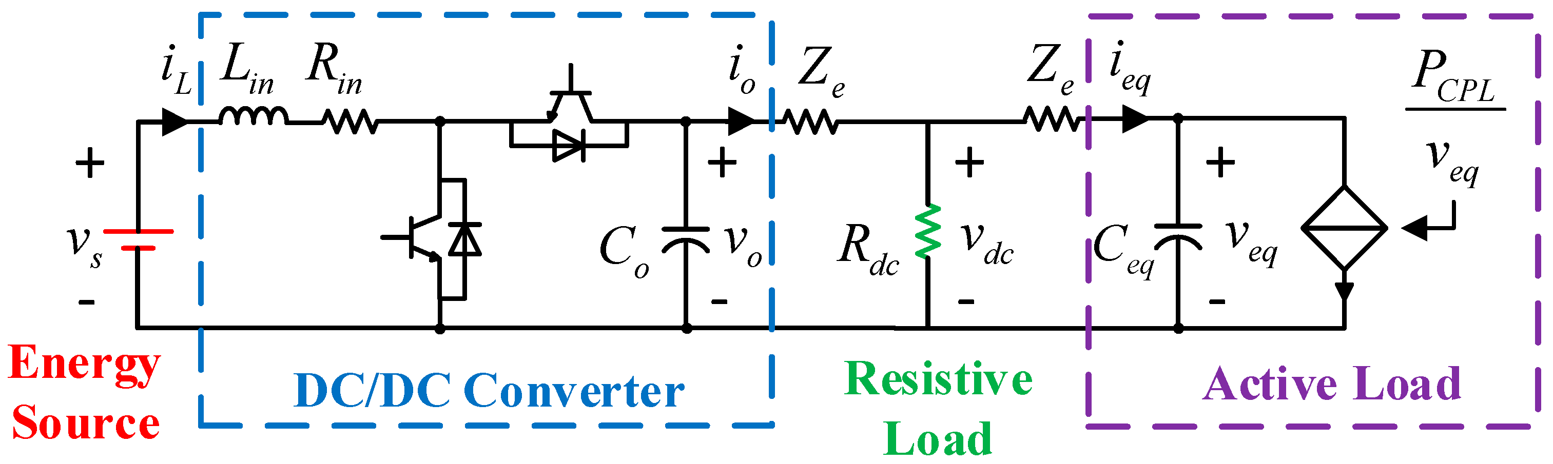
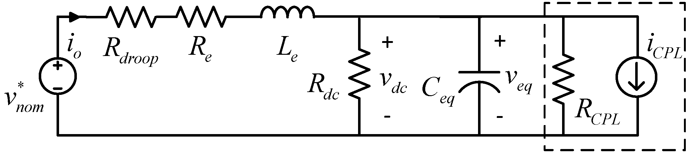
2. Problem Formulation

The detailed equivalent circuit diagram of the studied dc microgrid system is shown in Figure 1, which consists of one battery as the energy source, one bidirectional dc/dc converter, one equivalent resistive load, and one equivalent active load.
As shown in Figure 1, v s is the battery source voltage, v o is the converter output voltage, v d c is the dc bus voltage, v e q is the CPL-side capacitance voltage, i L is the inductance current, i o is the converter output current, P C P L is the CPL power, L i n and R i n are the input inductance and resistance, respectively, C o is the converter output capacitance, Z e is the line impedance, R d c is the equivalent resistive load, and C e q is the CPL-side capacitance. The system parameter values for the studied dc microgrid have been listed in Table 1.
For ensuring the proportional power sharing control among multiple parallel-connected sources, droop control method is adopted here, which can be expressed as follows:
v o * = v n o m * R d r o o p i o ,
where, v n o m * represents the nominal output voltage, R d r o o p is the droop coefficient, which can be obtained by the maximum allowable voltage deviation and maximum output current as follows:
R d r o o p = Δ v d c , max i o max  
If we neglect the source voltage dynamics, the studied DC microgrid system shown in Figure 1 can be simplified as shown in Figure 2.
where, R C P L is the negative incremental resistance of the CPL, which can be expressed as follows:
R C P L = v e q 2 P C P L ,  
Based on the Thevenin’s theorem, the dc bus voltage of the simplified equivalent circuit shown in Figure 2 can be derived as follows
v d c ( s ) = v n o m * ( s ) ( R d r o o p + R e + L e s ) i C P L ( s ) a 2 s 2 + a 1 s + a 0 ,  
where,
{ a 0 = 1 + ( R d r o o p + R e ) ( 1 / R d c + 1 / R C P L ) a 1 = C e q ( R d r o o p + R e ) + L e ( 1 / R d c + 1 / R C P L ) a 2 = C e q L e .  
For ensuring the system stability, we expect that there is no right half plane poles in (4). According to the Hurwitz stability condition ( a i > 0 ) and (5), the following inequality conditions should be fulfilled:
{ P C P L < v e q 2 [ 1 / ( R d r o o p + R e ) + 1 / R d c ] P C P L < v e q 2 [ C e q ( R d r o o p + R e ) / L e + 1 / R d c ] .  
As we can see from the second inequality of (6), a large line inductance L e will have an adverse effect on the maximum allowable CPL power. In other words, a large line inductance will decrease the system stability margin. For maintaining the stability of the studied dc microgrid system, a smaller line inductance L e would be preferred. However, as we know, the large line inductance is physically determined by the distributed nature of the dc microgrid system, which cannot be arbitrarily modified according to our needs. Therefore, traditional stabilizing methods always seek their ways by adding physical dampers or dc-link capacitors to the dc bus. Before [9], few stabilizing effort has ever been made from the sense of decreasing the line inductance. However, the effectiveness of the stabilizing strategy proposed in [9] is strongly dependent on the converter output current measurement. If the current sensor fails, the strategy will be invalid. Inspired by this fact, we try a different new way to stabilize the dc microgrid system, namely, the NDO based virtual VNI stabilizing strategy proposed in this paper.

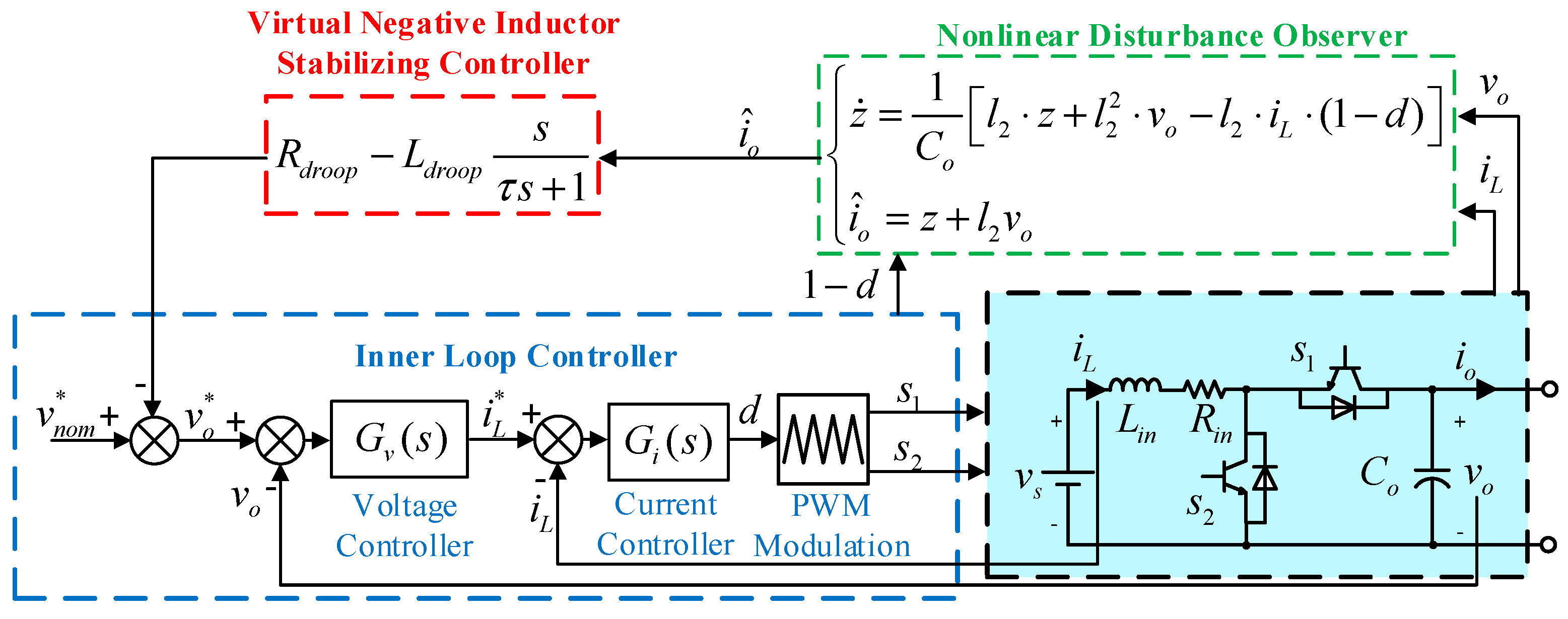
3. NDO Based VNI Stabilizing Strategy

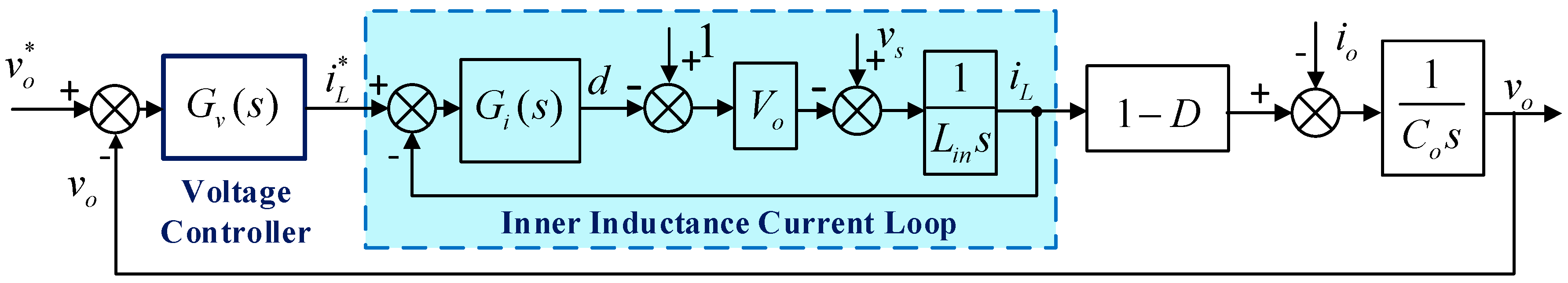
3.1. DC/DC Converter Modeling and Inner Loop Controller

We first assume that the dc/dc source converter will be always operating in the continuous current mode. Then, the state-space average model of the dc/dc converter can be expressed as follows:
{ L i n d i L d t = v s R i n i L ( 1 d ) v o C o d v o d t = ( 1 d ) i L i o L e d i o d t = v o R e i o v d c ,  
where, d is the average duty ratio of dc/dc converter. The corresponding definition of variables in (7) have been declared above, under Figure 1.
Conventional dual loop controller is adopted here for regulating the output voltage of the dc/dc converter, as depicted in Figure 3.
From Figure 3, we can calculate the closed-loop transfer functions of the inner inductance current loop and the output voltage loop as shown in (8) and (9). It should be mentioned that (9) is obtained here by neglecting the inner dynamics of the inductance current loop.
G C L i ( s ) = ( k p i s + k i i ) V o L i n s 2 + k p i V o s + k i i V o ,  
G C L v ( s )     = ( k p v s + k i v ) ( 1 D ) C o s 2 + k p v ( 1 D ) s + k i v ( 1 D ) ,  
where, k p i and k i i are the inductance current PI controller parameters, k p v and k i v are the output voltage PI controller parameters.
From (8) and (9), we can see that both the inductance current loop and the output voltage loop can be taken as the typical second-order system. The inner loop controller parameters can be easily determined by designating the system damping ratio ξ and the natural frequency ω based on the classical control theory. Due to the space limitation, the detailed parameter designing process for the inner loop controller is just omitted here. The final designing results and the corresponding system parameters have been listed in Table 1.

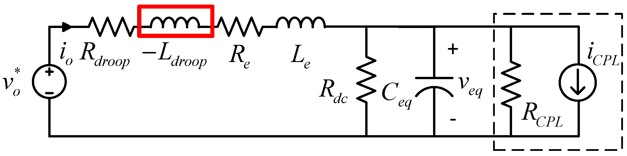
3.2. Virtual Negative Inductor Stabilizing Strategy

As stated in Section 2, a large line inductance may deteriorate the dc microgrid system stability margin. Because of the distributed nature of the dc microgrid system, the line inductance cannot be arbitrarily reduced according to our needs. For solving this problem, a virtual negative inductor (VNI) stabilizing strategy is proposed in this paper.
The proposed VNI stabilizing strategy is built on the source-side converter through the modified droop control method, which voltage reference value can be expressed as follows:
v o * = v n o m * [ R d r o o p + ( L d r o o p ) s ] i o ,  
where, s is the Laplacian operator, L d r o o p is the built VNI, v o * is the output voltage reference, v n o m * is the nominal value of the bus voltage, and i o is the output current.
For clearly illustrating the basic principles of the proposed stabilizing strategy, a simplified circuit of the proposed VNI is shown in Figure 4.
As shown in Figure 4, with the proposed VNI stabilizing strategy, a virtual negative inductor L d r o o p is built on the dc bus in series with the large line inductance L e . From the system point of view, the large line inductance L e will be counteracted by the built negative inductor L d r o o p , thus alleviating the large line inductance destabilizing effect.
As shown in (10), there is a pure differentiating operator in the designated output voltage reference, which may bring undesired high-frequency noises to system. For solving this problem, a low-pass filter is introduced here. The modified output voltage reference of the proposed VNI stabilizing strategy can be then expressed as follows:
v o * = v n o m * [ R d r o o p + ( L d r o o p ) s / ( τ s + 1 ) ] i o ,  
where, τ is the time constant of the introduced low-pass filter.

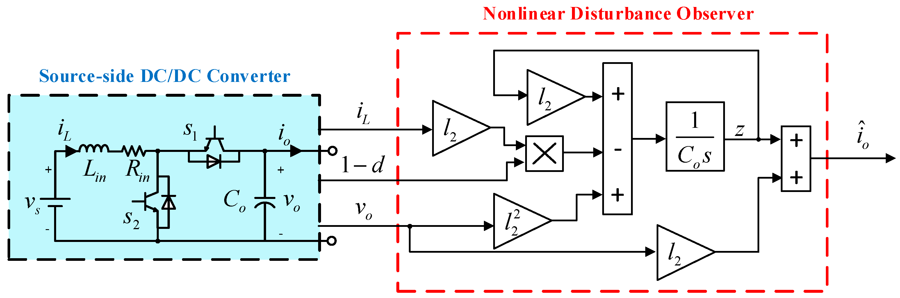
3.3. Nonlinear Disturbance Observer

From (11), we can see that the implementation of the proposed VNI stabilizing strategy requires an accurate measurement of the dc/dc converter output current i o . Consequently, the effectiveness of the proposed stabilizing strategy will be strongly dependent on the output current sensor. If the sensor fails, the proposed VNI stabilizing strategy will be invalid. For solving this current sensor failure problem, a nonlinear disturbance observer (NDO) for the source-side dc/dc converter is proposed here for estimating the output current. The basic structure of the proposed NDO is shown in Figure 5.
As shown in Figure 5, the NDO receives the output voltage v o , the inductance current i L , and the average duty ratio d as the input signals. For the continuity of description, the corresponding designing process of the NDO have been specified in the Appendix A. Only the final designing results of the NDO are presented here, which can be expressed as follows:
{ z ˙ = l 2 C o z + l 2 2 C o v o l 2 C o i L ( 1 d ) i ^ o = z + l 2 v o ,  
where, z is the dummy variable for the proposed NDO, l 2 is the observer gain to be designed, and i ^ o is the estimated output current.
With the NDO expressed in (12), we can relieve the strong dependence of the proposed VNI stabilizing strategy on the output current sensor. Before proceeding to the next combination of the proposed NDO with the VNI stabilizing strategy, we would like to analyze the effect of the proposed NDO here first.
As depicted in Appendix A, we find out that the effect of the proposed NDO shown in Figure 5 is equivalent to a simple first-order low-pass filter, which can be expressed as follows:
i ^ o ( s ) = 1 T N D O s + 1 i o ( s ) ,  
where, T N D O is the time constant of the equivalent low-pass filter, which can be expressed as
T N D O = C o l 2 .  
Based on (11) and (12), the detailed structure of the NDO based VNI stabilizing strategy for the studied dc microgrid system can be depicted as shown in Figure 6.
As shown in Figure 6, the estimated output current i ^ o from the NDO is directly sent to the VNI stabilizing controller, which modifies the output voltage reference v o * for the dc/dc converter. As shown in (11)–(14), there are three parameters remaining to be designed in the proposed NDO based VNI stabilizing strategy, namely, the virtual negative inductor L d r o o p , the time constant of the low-pass filter τ , and the time constant of the nonlinear disturbance observer T N D O .

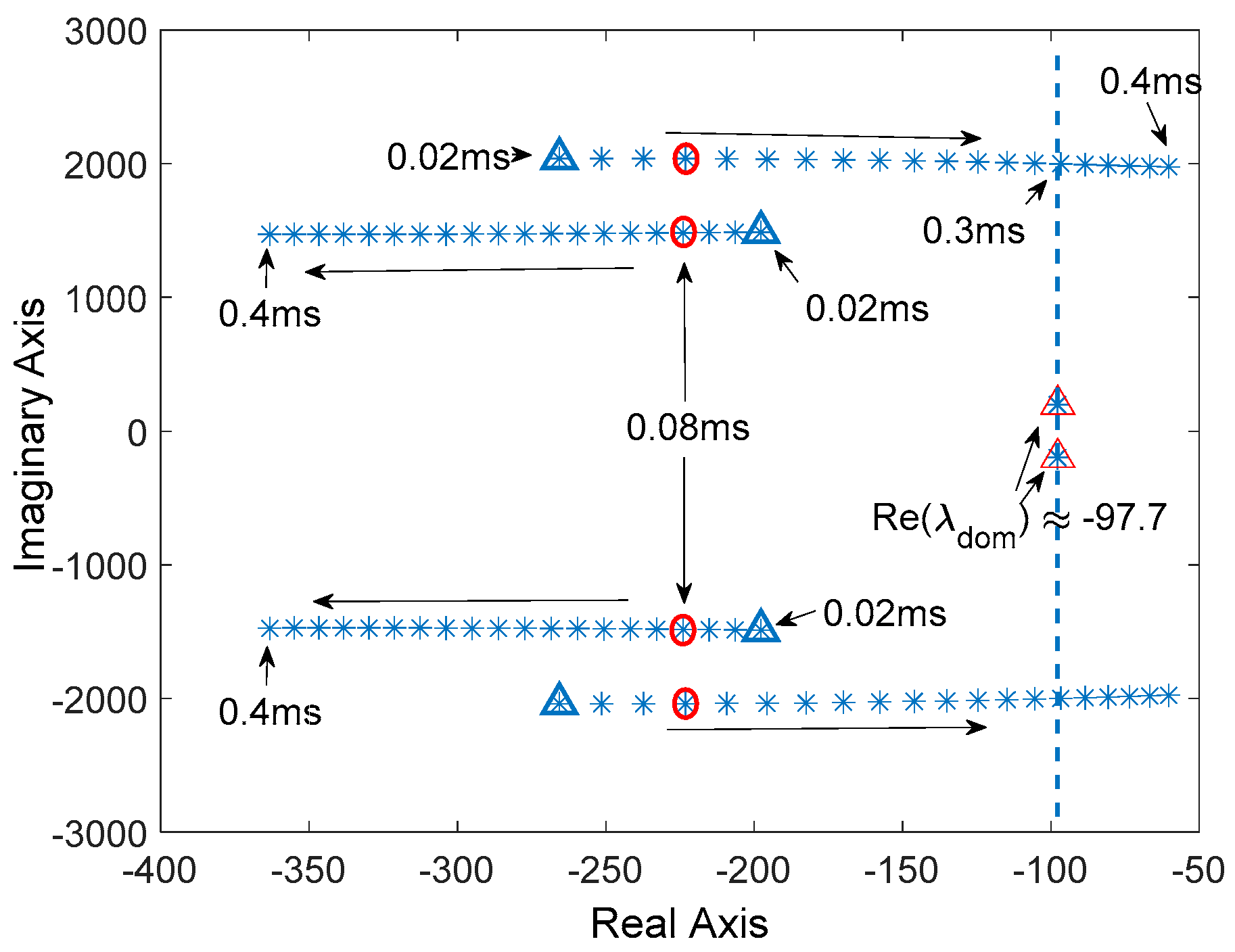
3.4. Parameter Designing

For maximizing the stability margins of the studied dc microgrid system, a system root-locus based approach is adopted here for the proposed NDO based VNI stabilizing strategy. In this parameter designing approach, the system root-locus are plotted with the three parameters to be designed varying from a smaller value to a larger one. The optimal parameter value will be the one that corresponds the point that is farthest away from the right-half-plane, which is also the most stable point for the system.
The small-signal model of the studied dc microgrid system is required for plotting the system root-locus diagram, which has been presented in the Appendix B. Based on the small-signal model, we can now plot the system root locus diagram.
As shown in Figure 7, the root locus of the studied dc microgrid system is plotted by varying the NDO time constant T N D O from 0.7 ms to 2.6 ms. As we can see from Figure 7, the allowable range for the nonlinear disturbance observer time constant T N D O is from 0.9 ms to 1.9 ms. If T N D O is too large or too small, the system root-locus will enter into the right half plane (RHP), making the system unstable. The optimal value for the NDO time constant T N D O is 1.2 ms, which makes the system dominant poles farthest away from the RHP.
As shown in Figure 8, with the time constant of the NDO set to be 1.2 ms, the system root-locus diagram is plotted with the virtual negative inductor L d r o o p varying from 0.02 mH to 0.4 mH. It can be observed that there is an inflection point (0.1 mH) in the system root-locus diagram, which is also the dominant poles farthest away from the RHP. Therefore, the optimal value for the L d r o o p can be confirmed to be 0.1 mH from Figure 8.
With the NDO time constant set to be 1.2 ms and the virtual negative inductor set to be 0.1 mH, we vary the low-pass filter time constant from 0.02 ms to 0.4 ms. The corresponding system root locus diagram for this case is shown in Figure 9.
As shown in Figure 9, as long as the low-pass filter time constant τ is lower than 0.3 ms, the system dominant poles will always be the pole-pairs with the negative real parts nearly −97.7. Hence, the system stability characteristics will not be affected with the low-pass filter time constant varying from 0.02 ms to 0.3 ms. However, as shown in Figure 9, there are two branches for the sub-dominant poles when increasing the low-pass filter time constant, one from the left to the right, and the other from the right to the left. For ensuring the fast convergence of the system, we select the most negative sub-dominant poles for the low-pass filter time constant here, namely, 0.08 ms.
The detailed implementation procedure of the proposed root locus diagram based parameter designing approach is summarized as follows:
Step 1: Start;
Step 2: Construct the small signal model of the studied dc microgrid system;
Step 3: Calculate the system eigenvalues based on the small-signal model;
Step 4: Determine the optimal value of the nonlinear disturbance observer gain T N D O from the root locus diagram shown in Figure 7;
Step 5: Determine the optimal value of the virtual negative inductor L d r o o p from the root locus diagram shown in Figure 8;
Step 6: Determine the optimal value of the low-pass filter time constant τ from the root locus diagram shown in Figure 9;
Step 7: End.
For the clearance of description, the stabilizer parameter designing results have been summarized in Table 2.

4. Stability Analysis

In this section, the stability of the proposed NDOB-VNI stabilizing strategy is studied with the impedance-based stability analysis method. The output impedance model of the dc/dc converter is first presented. And the Nyquist stability criterion for the studied dc microgrid system is carefully derived. With the help of the system Nyquist diagram, three cases are analyzed for studying the robustness of the proposed NDOB-VNI stabilizing strategy to the system perturbations. These three cases include the change of the CPL power, the variations of the droop coefficient, and the perturbations of the CPL-side capacitance.

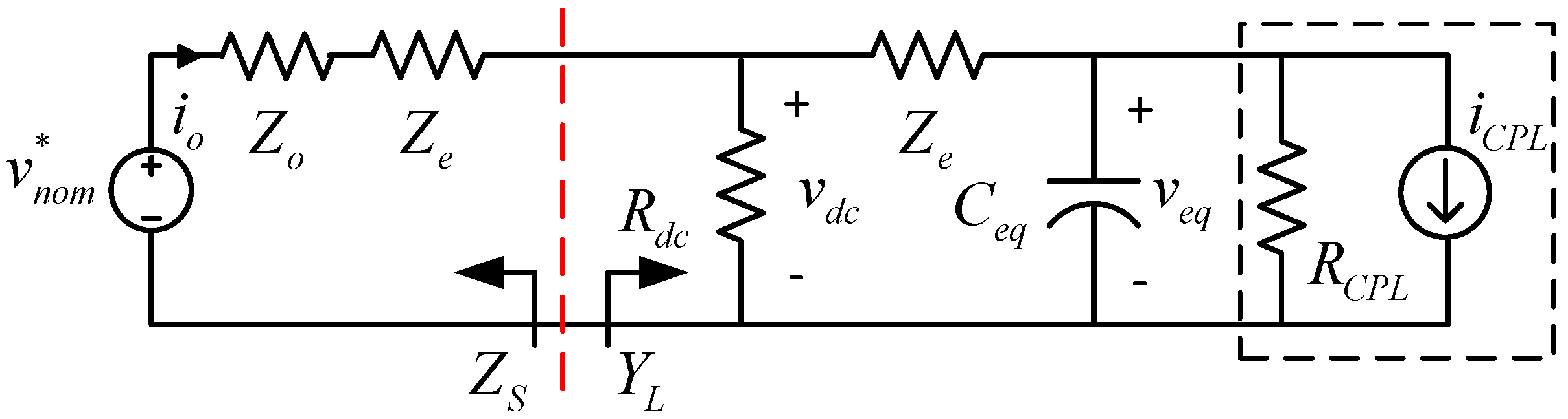
4.1. Output Impedance Model of the DC/DC Converter

Based on the small-signal model obtained in (B1), we can plot the small-signal model diagram of the dc/dc converter, as shown in Figure 10.
where,
A v o ( s ) = Δ v o ( s ) Δ v s ( s ) = 1 D L i n C o s 2 + R i n C o s + ( 1 D ) 2 ,  
Z o u t ( s ) = Δ v o ( s ) Δ i o ( s ) = L i n s + R i n L i n C o s 2 + R i n C o s + ( 1 D ) 2 ,  
G v d ( s ) = Δ v o ( s ) Δ d ( s ) = L i n I L s R i n I L + V s L i n C o s 2 + R i n C o s + ( 1 D ) 2 ,  
Y i o ( s ) = Δ i L ( s ) Δ v s ( s ) = C o s L i n C o s 2 + R i n C o s + ( 1 D ) 2 ,  
A i o ( s ) = Δ i L ( s ) Δ i o ( s ) = ( 1 D ) L i n C o s 2 + R i n C o s + ( 1 D ) 2 ,  
G i d ( s ) = Δ i L ( s ) Δ d ( s ) = C o V o s + I L ( 1 D ) L i n C o s 2 + R i n C o s + ( 1 D ) 2 ,  
G N D O ( s ) = Δ i o e s t ( s ) Δ i o ( s ) = 1 T N D O s + 1 ,  
Z d r o o p ( s ) = R d r o o p + ( L d r o o p ) s τ s + 1 .  
The output impedance model of the dc/dc converter can be then obtained from Figure 10 as follows:
Z o ( s ) = Δ v o ( s ) Δ i o ( s ) = ( Δ v o ( s ) Δ i o ( s ) | C H 1 + Δ v o ( s ) Δ i o ( s ) | C H 2 + Δ v o ( s ) Δ i o ( s ) | C H 3 ) ,  
where,
Δ v o ( s ) Δ i o ( s ) | C H 1 = Z o u t ( 1 + G i G i d ) 1 + G i G i d + G v G i G i d ,  
Δ v o ( s ) Δ i o ( s ) | C H 2 = A i o G i G v d 1 + G i G i d + G v G i G v d ,  
Δ v o ( s ) Δ i o ( s ) | C H 3 = Z d r o o p G N D O G v G i G v d 1 + G i G i d + G v G i G v d .  

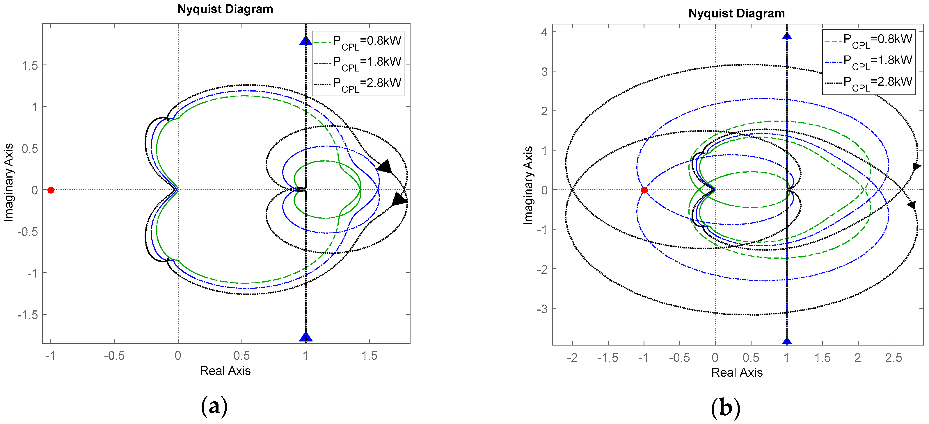
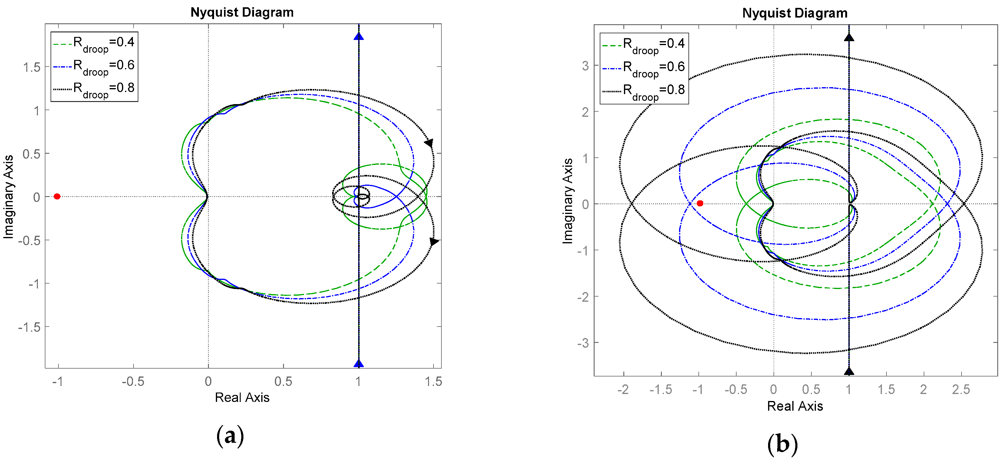
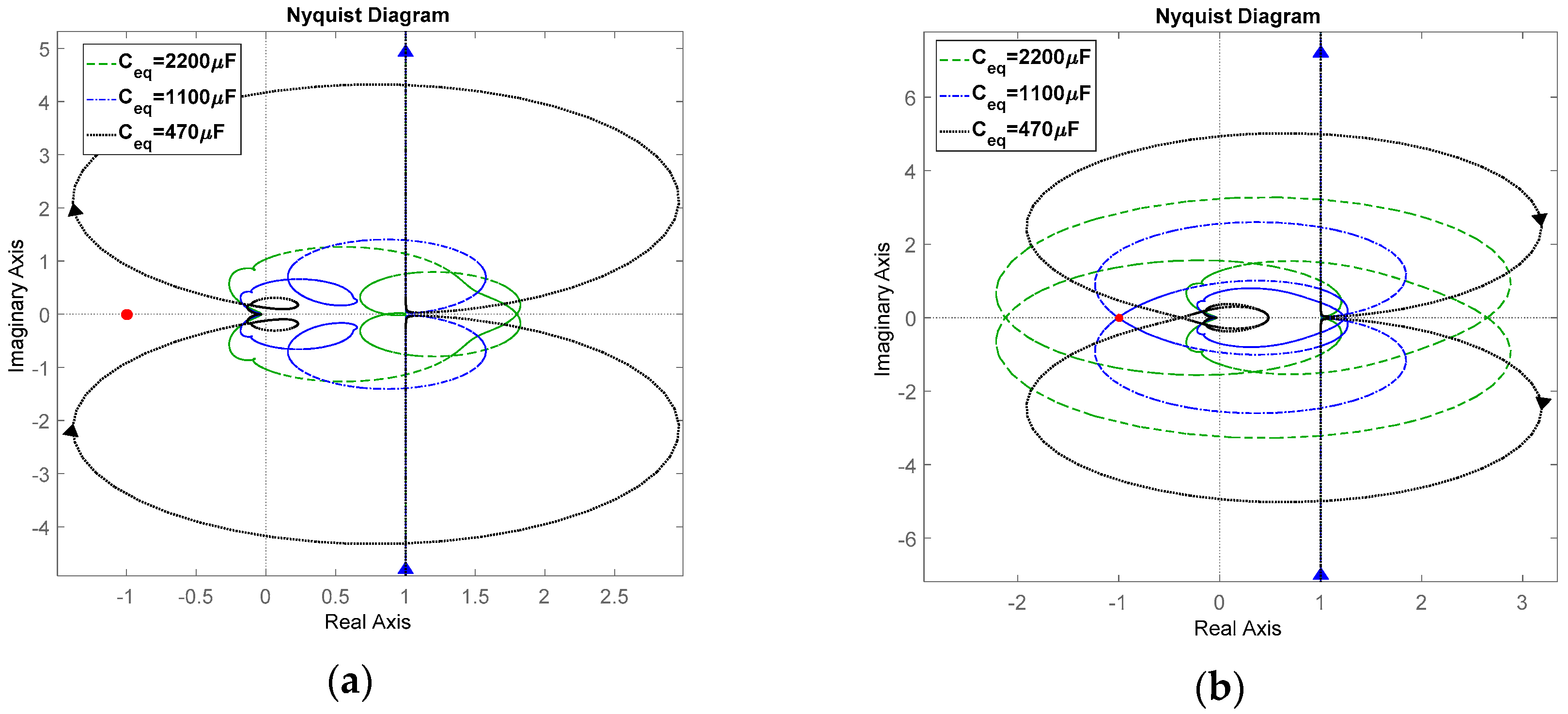
4.2. Nyquist Stability Criterion

The equivalent circuit diagram of the studied dc microgrid system considering the source dynamics is illustrated in Figure 11, where, Z o is the output impedance of the dc/dc converter, Z e is the line impedance, C e q is the equivalent CPL-side capacitance, and R d c is the equivalent resistive load.
As shown in Figure 11, the dc bus voltage v d c can be expressed as
v d c = v n o m * Z o + Z e 1 + Z e ( C e q s + 1 / R C P L ) i C P L 1 + ( Z o + Z e ) [ 1 R d c + 1 Z e + 1 / ( C e q s + 1 / R C P L ) ] .  
The stability of the studied dc microgrid system can be ensured if there is no right-half-plane poles in (28). For the clearance of description, we can reorganize the denominator in (28) as follows
D ( s ) = 1 + Z S Y L = 1 + T M ,  
where, Z S is the source output impedance, Y L is the load input admittance, and T M is the system minor loop gain, which can be expressed as follows
T M = Z S Y L  
Z S = Z o + Z e ,  
Y L = 1 / R d c + 1 / [ Z e + 1 / ( C e q s + 1 / R C P L ) ] .  
According to the Argument Principle, the number of RHZ in (29) can be calculated by the number of times that Nyquist trajectory encircles the point (−1,0):
R H Z ( 1 + Z S Y L ) = N ( 0 , 0 ) ( 1 + Z S Y L ) + R H P ( 1 + Z S Y L ) = N ( 0 , 0 ) ( 1 + Z S Y L ) =    N ( 1 , 0 ) ( Z S Y L ) = N ( 1 , 0 ) ( T M )
where, N ( 0 , 0 ) and N ( 1 , 0 ) are the number of times that Nyquist trajectory encircles the point (0,0) and the point (−1,0) in clockwise direction, respectively. It should be mentioned that as the source and CPL are designed to be stable alone, the R H P ( 1 + Z S Y L ) would be just zero in (33).
Therefore, the system stability analysis problem is then transformed into judging whether the Nyquist trajectory of T M encircles the critical point (−1,0):
(a)
If N ( 1 , 0 ) ( Z S Y L ) equals to zero, the system will be stable;
(b)
Or else, the system will be unstable.

4.3. Comparative Stability Analysis

With the output impedance model of the dc/dc converter and the Nyquist based stability criterion stated above, we will conduct the comparative stability analyses for the studied dc microgrid system in this section.

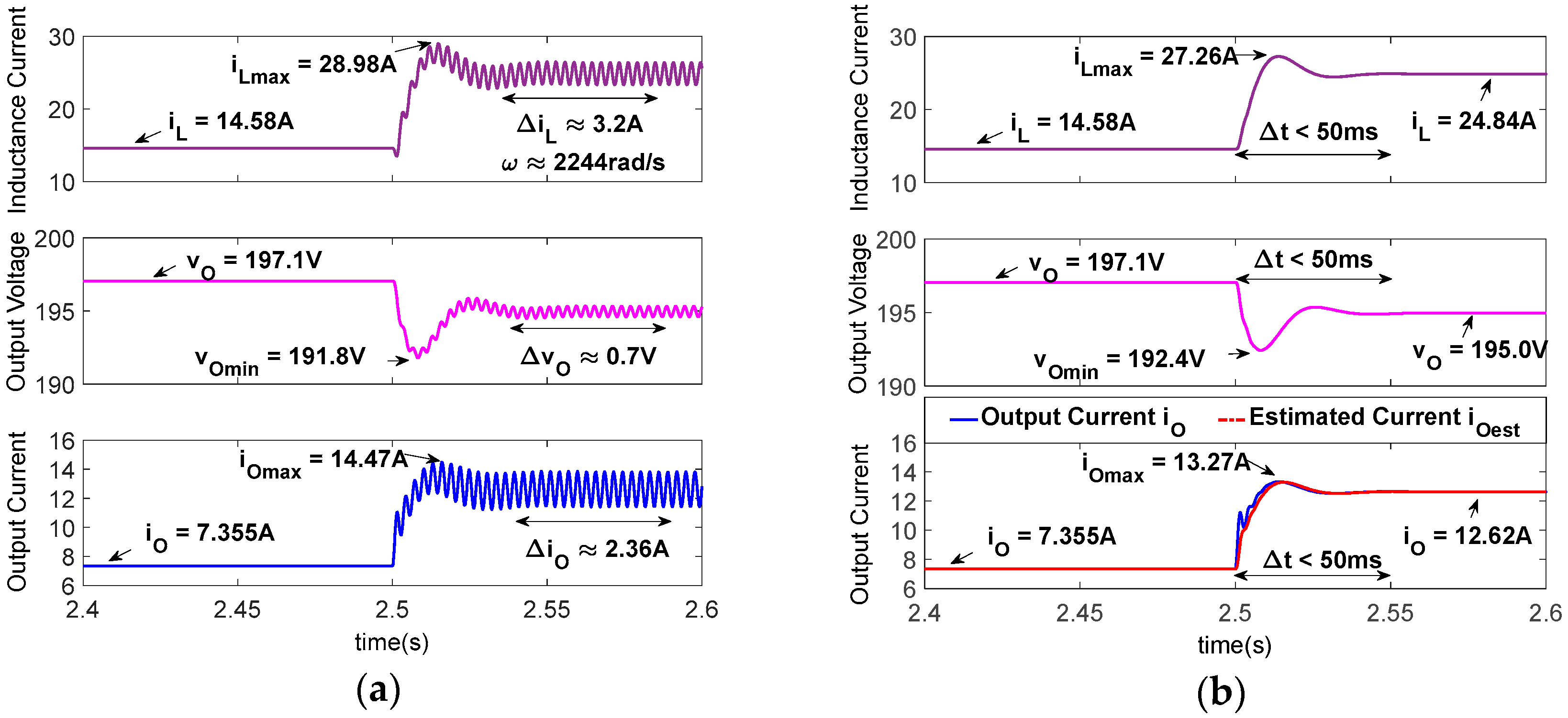
4.3.1. Case 1: CPL Power Change

In this case, three same CPL power conditions are considered for these two comparative systems, which are 0.8 kW, 1.8 kW, and 2.8 kW, respectively. The parameter settings for this comparative case have been listed in Table 1 and Table 2. The comparative stability analysis results are shown in Figure 12.
As shown in Figure 12a, all of the Nyquist trajectories of the NDOB-VNI controlled dc microgrid system do not encircle the critical point (−1,0), which means the system remains stable for the CPL power change under the proposed NDOB-VNI stabilizing strategy. However, as shown in Figure 12b, the Nyquist trajectories for the conventional droop controlled system with 1.8 kW and 2.8 kW CPL power encircle the point (−1,0), which means that the conventional droop controlled system are unstable with the CPL power change. The proposed NDOB-VNI stabilizing strategy shows a better robustness to the CPL power change.

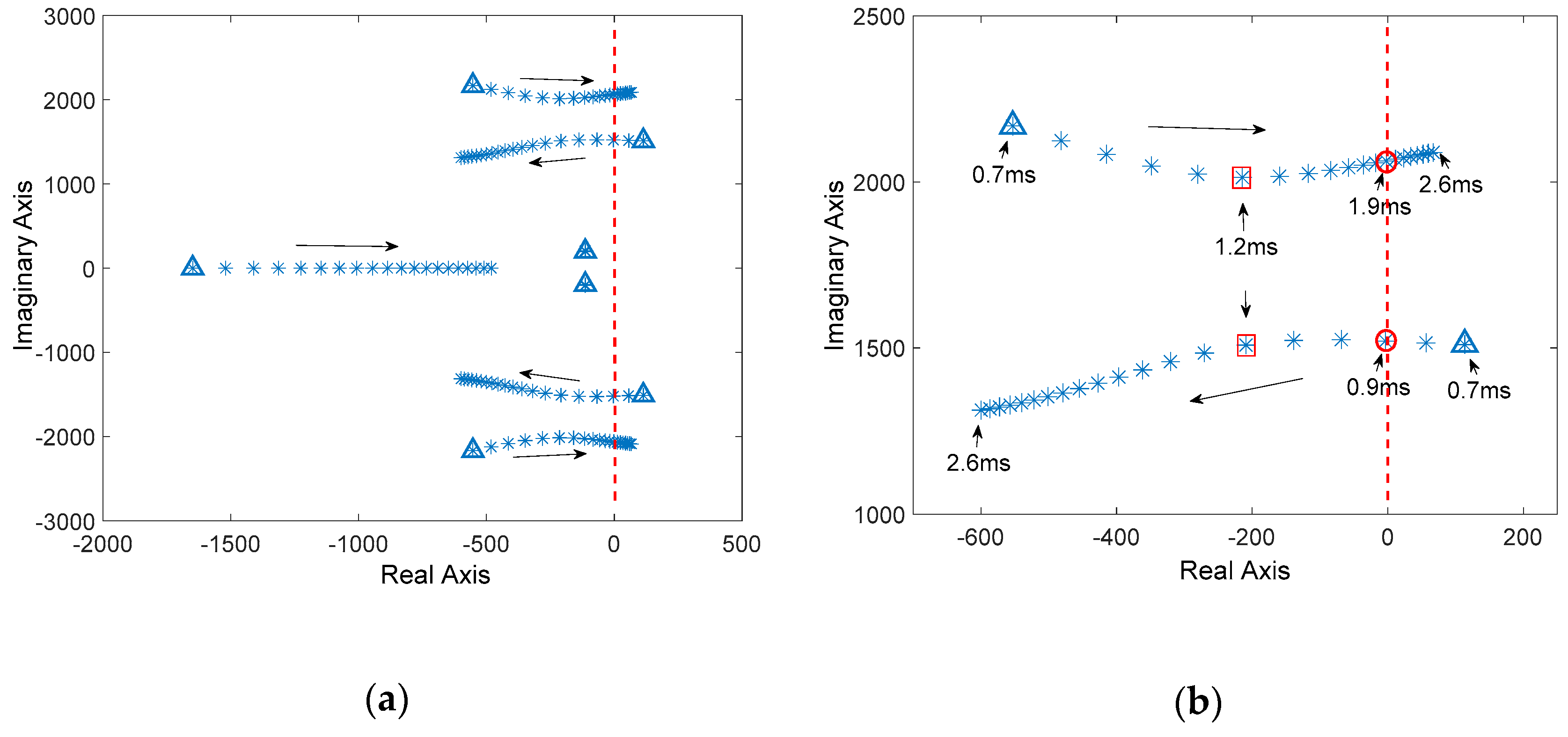
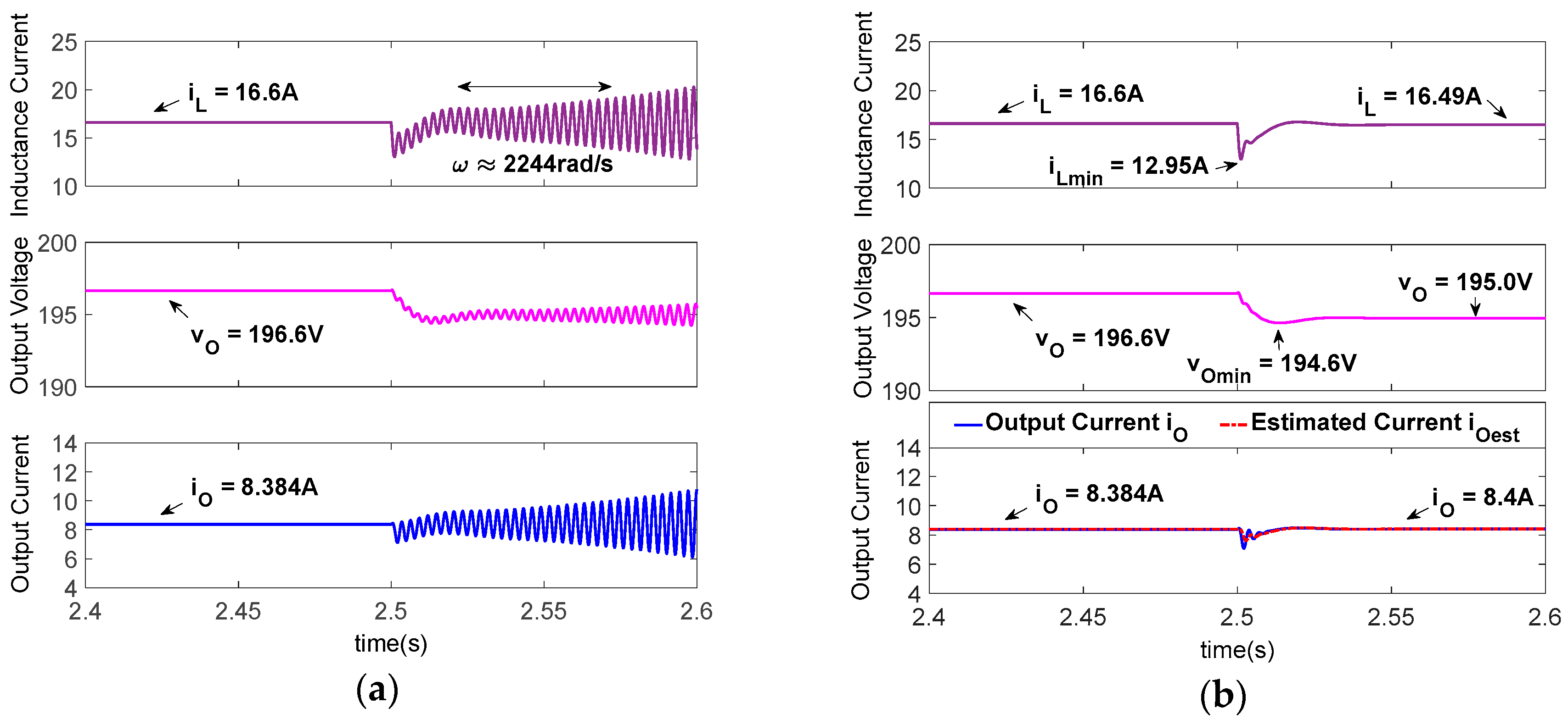
4.3.2. Case 2: Droop Coefficient Variation

During the system operation, the droop coefficient may be adjusted online for balance of the battery state of charge. The varying droop coefficient may impact the system stability. Therefore, in this case, comparative stability analysis are conducted for the dc microgrid system with a varying droop coefficient, as shown in Figure 13. Three droop coefficients are considered, namely, 0.4, 0.6, and 0.8, respectively.
From Figure 13, we can see that a large droop coefficient may have an adverse effect on the system stability. As shown in Figure 13a, all of the three Nyquist trajectories for the NDO based VNI controlled dc microgrid system do not encircle the critical point (−1,0), which means the NOD based VNI strategy is robust to the droop coefficient variation. However, as shown in Figure 13b, for the conventional droop controlled system with droop coefficients of 0.6 and 0.8, the system Nyquist trajectories do encircle the critical point (−1,0), which means that the conventional droop controlled system is unstable with the droop coefficient variation.

4.3.3. Case 3: CPL-side Capacitance Perturbation

During the system operation, the CPL-side capacitance C e q may be varying due to the connection or disconnection of the CPL. For illustrating this impact on the system stability, three CPL-side capacitances are considered in this case, which are 2000 μ F , 1100 μ F , and 470 μ F , respectively. The comparative stability analysis results of the studied dc microgrid system with a varying CPL-side capacitance are shown in Figure 14.
As shown in Figure 14a, all of the three Nyquist trajectories for the NDO based VNI controlled system do not encircle the critical point (−1,0), which means that the proposed NDO based VNI stabilizing strategy is robust to the CPL-side capacitance perturbation. However, for the conventional droop controlled system, the case with capacitance of 2200 μ F and 1100 μ F are unstable.
Different from the conventional view, we can see from Figure 14b that a large dc-link capacitance, on the contrary, will destabilize the studied dc microgrid system. In the studied dc microgrid system, the large line inductance and the CPL-side capacitance form an undamped LC circuit, which has a resonance frequency similar to the control bandwidth of the converter inner inductance current loop. The resonance frequency overlap is the key point that causes the system high-frequency oscillations. Particularly, for the studied dc microgrid system, the decrease of the CPL-side capacitance is the right direction to eliminate this frequency overlap, coincidently. Therefore, we cannot draw a general conclusion about how the CPL-side capacitance impacts the system stability. But what we can confirm is that the proposed NDO based VNI stabilizing strategy shows a better robustness to the CPL-side capacitance perturbation.

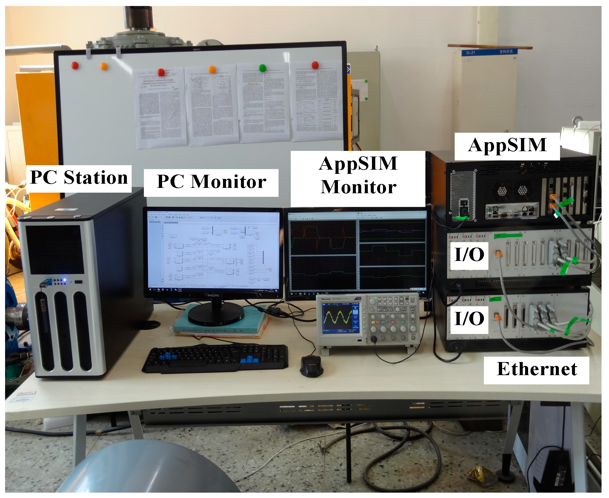
5. Numerical Simulations

In this section, detailed real-time simulations are conducted for validating the effectiveness of the proposed NDO based VNI stabilizing strategy. The experiment setup is shown in Figure 15, which consists of an AppSIM real-time simulator enabling a detailed simulation of the studied dc microgrid system. Three comparative simulating cases are studied here, which aim at validating the effectiveness and robustness of the proposed stabilizing strategy. The system parameters used for simulation have been listed in Table 1 and Table 2.

5.1. Effectiveness Validation

In the first case, transient numerical simulations are conducted for showing the effectiveness of the proposed stabilizing strategy. The system parameters set for this case have been listed in Table 1 and Table 2. The CPL power for two comparative systems steps up from 0.8 kW to 1.8 kW at the time of 2.5 s, as shown in Figure 16.
As shown in Figure 16a, when the CPL power steps up from 0.8 kW to 1.8 kW, the conventional droop controlled system starts to oscillate with a frequency nearly 2244 rad/s. The oscillation amplitudes of the dc/dc converter inductance current, output voltage, and output current are 3.2 A, 0.7 V, and 2.36 A, respectively. The peak values of the corresponding variables are 28.98 A, 191.8 V, and 14.47 A, respectively.
As shown in Figure 16b, the proposed NDOB-VNI stabilizing strategy controlled system remains stable with the step change of the CPL power. Moreover, the estimated output current tracks the real output current well. With the proposed NODB-VNI stabilizing strategy, the perturbed dc microgrid system is restored to a new stable state within 50 ms, which shows an excellent dynamics. Moreover, the peak value of the dc/dc converter inductance current, output voltage and output current are 27.26 A, 192.4 V, and 13.27 A respectively, which are lower than that of the conventional droop controlled system listed above. From the simulation results shown in Figure 11, we can see that the proposed NDOB-VNI stabilizing strategy shows a better robustness to the CPL power variations. The effectiveness of the proposed NDOB-VNI stabilizing strategy is validated.
It should be noted that in Figure 16b, the NDO estimated value is different from the real output current during the system transient stage. This dynamic difference is indeed caused by the limited convergence rate of the NDO. We have pointed out that the estimating effect of NDO is equivalent to a first order low-pass filter in Section 3. The dynamic difference between i ^ o and i o shown in Figure 16b is in fact caused by the low-pass filtering effect of the NDO. Similarly, observable differences can be also found in the following simulating cases. Moreover, we have considered this dynamic error during the designing process. Therefore, this slight difference will not affect the effectiveness of the proposed stabilizing strategy.

5.2. Test of Droop Coefficient Variation

For validating the robustness of the proposed stabilizing strategy to the droop coefficient variation, a comparative simulation case is studied here, as shown in Figure 17. The droop coefficient varies from 0.4 to 0.6 at the time of 2.5 s for both two comparative systems, with the CPL power equal to 1 kW. The system parameters for this case have been listed in Table 1 and Table 2.
As shown in Figure 17a, when the droop coefficient varies from 0.4 to 0.6, the conventional droop controlled system starts to oscillate with a frequency nearly 2244 rad/s. The studied dc microgrid system becomes unstable, which is also consistent with the system stability analysis results shown in Figure 12.
On the contrary, as shown in Figure 17b, the proposed NDOB-VNI stabilizing strategy controlled system remains stable. The estimated output current also follows the real output current well. The system is restored to a new stable state within 50 ms, which also shows a great dynamic characteristics with acceptable instant peak values of system variables. From Figure 17, we can see that a large droop coefficient may deteriorate the stability of the conventional droop controlled system. But with the proposed NDOB-VNI stabilizing strategy, the studied dc microgrid system could be more robust to the droop coefficient variation.

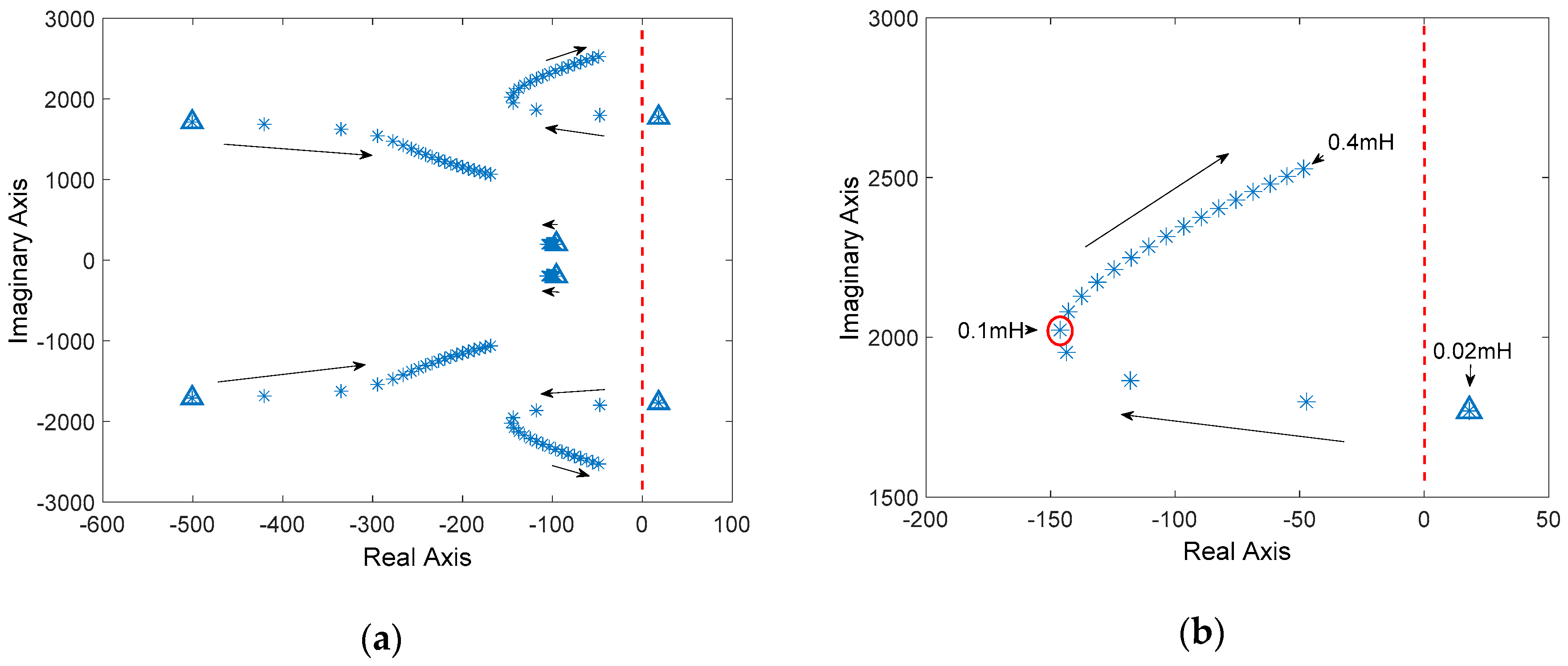
5.3. Test of CPL-Side Capacitance Variations

In this simulation case, the robustness of the proposed NDOB-VNI stabilizing strategy to the variations of the CPL-side capacitance is tested, as shown in Figure 18. The CPL-side capacitance varies from 470 μ F to 1100 μ F at the time of 2.5 s, with the CPL power of 2.9 kW.
As shown in Figure 18a, the conventional droop controlled system is initially operating in a stable state with the 470 μ F CPL-side capacitance. At the time of 2.5 s with the variations of CPL-side capacitance from 470 μ F to 1100 μ F , the conventional droop controlled system starts to oscillate with a frequency of 2244 rad/s. Different from the conventional view that a large dc capacitance may help to stabilize the system, we can see that a large CPL-side capacitance will indeed, on the other way, destabilize the system.
However, as shown in Figure 18b, the NDOB-VNI stabilizing strategy controlled dc microgrid system remains stable with the variations of the CPL-side capacitance. And the new steady-state value of the system variables remains almost unchanged as shown in Figure 18b. We can easily find out from the simulation results that the proposed NDOB-VNI stabilizing strategy shows a better robustness to the CPL-side capacitance variations than that of the conventional droop control method.
As shown in Figure 16, Figure 17 and Figure 18, the proposed NDOB-VNI stabilizing strategy controlled dc microgrid system shows a better stability to the variations of CPL power, droop coefficient and CPL-side capacitance. Therefore, the effectiveness and robustness of the proposed NDOB-VNI stabilizing strategy for the perturbed dc microgrid system can be validated.

6. Conclusions

In this paper, a NDO based VNI stabilizing strategy is proposed for the dc microgrid system with CPLs. The proposed strategy builds a VNI on the source-side converter through the modified droop control method, which counteracts the large line inductance, hence improves the system stability. A NDO is constructed on the source side converter for estimating the output current, thus alleviating the sensor failure problem. Moreover, we theoretically prove that the effect of the built nonlinear disturbance observer is equivalent to a first order low-pass filter, which illustrates the impact of the proposed NDO on the system dynamics. Small-signal models of the studied dc microgrid system are carefully derived. And a root-locus based parameter designing approach is adopted for obtaining the optimal controller parameter value. An explicit Nyquist stability criterion is established and with the help of the system Nyquist diagram, robustness to the CPL power change, the droop coefficient variation and the CPL-side capacitance perturbation are comparatively studied. From the analysis result, we prove that the proposed NDOB-VNI stabilizing strategy shows a better robustness these system perturbations. Detailed real-time simulations are also conducted for validating the effectiveness of the proposed NDO based VNI stabilizing strategy. As the proposed NDO based VNI stabilizing strategy is implemented in a totally decentralized manner, the single-point-failure problem in the central controller is then alleviated. Only the local measurement of the source-side converter is required for implementing the proposed strategy, which saves the high-bandwidth communications between multiple energy sources. As the implementation process of the proposed stabilizing strategy does not require any global system information, the proposed stabilizing strategy can be used regardless of the system topology. However, the proposed NDO based VNI stabilizing strategy is only applicable for the dc/dc converter operating as the voltage terminal under the droop control method. In future, an improved version of the proposed stabilizing strategy applicable for more different operational conditions would be expected.

Author Contributions

Conceptualization, S.L. and P.S.; Formal analysis, S.L. and P.S.; Funding acquisition, S.L.; Investigation, P.S.; Methodology, P.S.; Project administration, S.L. and L.Z.; Resources, S.L. and L.Z.; Software, P.S.; Supervision, S.L.; Validation, P.S.; Writing–original draft, P.S.; Writing–review & editing, P.S.

Funding

This research was funded in part by the National Natural Science Foundation of China Subsidization Project under Grant 51579047, in part by the Open Project Program of the State Key Laboratory of Millimeters Waves under Grant k201707, in part by the Natural Science Foundation of Heilongjiang Province under Grant QC2017048, in part by the Harbin Natural Science Foundation under Grant 2016RAQXJ077, and in part by the Central Fundamental Research Funds for Colleges and Universities under Grant HEUCF180407.

Conflicts of Interest

The authors declare no conflict of interest.

Appendix A

We first reorganize the dc/dc converter model (7) as the standard nonlinear affine form as follows:
[ x ˙ 1 x ˙ 2 ] = [ ( v s R i n x 1 ) L i n 0 ] f ( x ) + [ x 2 L i n x 1 C o ] g 1 ( x ) u + [ 0 1 C o ] g 2 ( x ) w ,  
where, x is the state variable including the converter inductance current and output voltage, which can be expressed as
x = [ x 1 , x 2 ] T = [ i L , v o ] T ,  
u is the input signal, namely the duty ratio for the dc/dc converter
u = 1 d ,  
w is the disturbance signal to be estimated, namely the converter output current
w = i o ,  
and f ( x ) is the system equation, g 1 ( x ) is the input channel function, and g 2 ( x ) is the disturbance channel function.
The standard NDO functions for (A1) can be expressed as follows:
{ z ˙ = l ( x ) g 2 ( x ) z l ( x ) [ g 2 ( x ) p ( x ) + f ( x ) + g 1 ( x ) u ] w ^ = z + p ( x ) ,  
where, w ^ is the estimated value, z is the internal state of the NDO, p ( x ) is the nonlinear function of NDO to be designed, and l ( x ) is the NDO gain, which can be expressed as
l ( x ) = p ( x ) x = [ p ( x ) x 1 , p ( x ) x 2 ] = [ l 1 ( x ) , l 2 ( x ) ] .  
Here, we define the NDO estimation error as follows:
e w = w ^ w = i ^ o i o .  
The dynamics of the NDO estimation error can be calculated from (A1) and (A5)–(A7) as follows:
e ˙ w = w ^ ˙ w ˙ = z ˙ + p ( x ) x x ˙ w ˙ = l ( x ) g 2 ( x ) e w w ˙ = l 2 ( x ) C o e w w ˙
As indicated in (A8), l 1 ( x ) has no impact on the dynamics of the NDO estimation error, which can be set to be zero for simplicity. Moreover, we can see that if:
(a)
the NDO observer gain satisfies
l 2 ( x ) < 0 ,  
(b)
and the disturbance signal tends to be constant as the time goes to the infinity
lim t w ˙ 0 ,  
the NDO estimation error shown in (A8) will have a ultimate asymptotically stable point at e w = 0 , which means that the estimated current i ^ o will eventually converge to the real one i o .
Here, we take the nonlinear disturbance observer gain l 2 ( x ) as a negative constant for simplicity, namely,
l 2 ( x ) = p ( x ) x 2 = l 2 < 0.  
Then, from (A1), (A5), (A6), and (A11), the nonlinear disturbance observer designed for the dc/dc converter output current can be expressed as follows:
{ z ˙ = l 2 C o z + l 2 2 C o v o l 2 C o i L ( 1 d ) i ^ o = z + l 2 v o ,  
where, i ^ o is the estimated output current.
The proposed NDO can be equivalent to a first-order low-pass filter. Substitute the physical variables definition in (A1)–(A4) and (A7) into (A8), we can obtain
d ( i ^ o i o ) d t = l 2 C o ( i ^ o i o ) d i o d t .  
Replacing the differentiator in (A13) with the Laplacian operator s , we can reorganize the equation in (A13) as follows:
i ^ o ( s ) = 1 T N D O s + 1 i o ( s ) ,  
where, T N D O is the time constant of the NDO, which can be expressed as follows:
T N D O = C o l 2 .  

Appendix B

The small-signal model of the studied dc microgrid system under the proposed NDO based VNI stabilizing strategy can be expressed as follows:
{ Δ v ˙ o = [ ( 1 D ) Δ i L I L Δ d Δ i o ] / C o Δ i ˙ L = [ Δ v s R Δ i L ( 1 D ) Δ v o + V o Δ d ] / L i n Δ i ˙ o = ( Δ v o R e Δ i o Δ v d c ) / L e Δ i ˙ e q = ( Δ v d c R e Δ i e q Δ v e q ) / L e Δ v ˙ e q = ( Δ i e q Δ i C P L ) / C e q Δ x ˙ v r = Δ v o * R d r o o p Δ i o e s t + L d r o o p Δ x V N I Δ v o Δ x ˙ i r = k p v ( Δ v o * R d r o o p Δ i o e s t + L d r o o p Δ x V N I Δ v o )      + k i v Δ x v r Δ i L Δ z ˙ = l 2 2 C o Δ v o l 2 C o ( 1 D ) Δ i L + l 2 C o Δ z + l 2 C o I L Δ d Δ x ˙ V N I = [ l 2 2 C o Δ v o l 2 C o Δ i o + l 2 C o Δ z Δ x V N I ] / τ Δ i o e s t = Δ z + l 2 Δ v o Δ d = k p i [ k p v ( Δ v o * R d r o o p Δ i o e s t + L d r o o p Δ x V N I Δ v o )    + k i v Δ x v r Δ i L ] + k i i Δ x i r Δ i C P L = ( P C P L / V e q 2 ) Δ v e q Δ v d c = R d c ( Δ i o Δ i e q )
where, Δ represents the small perturbation of the variable, and the uppercase letters V and I represent the steady state values of voltage and current, respectively, i o e s t is the estimated output current. And x v r , x i r , z and x V N I represent the inner states of the voltage controller, current controller, NDO, and VNI stabilizing controller, respectively.

References

  1. Dragicevic, T.; Lu, X.; Vasquez, J.C.; Guerrero, J.M. DC Microgrids-Part I: A Review of Control Strategies and Stabilization Techniques. IEEE Trans. Power Electron. 2016, 31, 4876–4891. [Google Scholar] [CrossRef]
  2. Dragicevic, T.; Lu, X.; Vasquez, J.C.; Guerrero, J.M. DC Microgrids-Part II: A Review of Power Architectures, Applications, and Standardization Issues. IEEE Trans. Power Electron. 2016, 31, 3528–3549. [Google Scholar] [CrossRef]
  3. Zhao, X.; Li, Y.W.; Tian, H.; Wu, X. Energy Management Strategy of Multiple Supercapacitors in a DC Microgrid Using Adaptive Virtual Impedance. IEEE J. Emerg. Sel. Top. Power Electron. 2016, 4, 1174–1185. [Google Scholar] [CrossRef]
  4. Lu, X.; Guerrero, J.M.; Sun, K.; Vasquez, J.C. An Improved Droop Control Method for DC Microgrids Based on Low Bandwidth Communication with DC Bus Voltage Restoration and Enhanced Current Sharing Accuracy. IEEE Trans. Power Electron. 2014, 29, 1800–1812. [Google Scholar] [CrossRef]
  5. Gu, Y.; Xiang, X.; Li, W.; He, X. Mode-Adaptive Decentralized Control for Renewable DC Microgrid with Enhanced Reliability and Flexibility. IEEE Trans. Power Electron. 2014, 29, 5072–5080. [Google Scholar] [CrossRef]
  6. Anand, S.; Fernandes, B.G.; Guerrero, J.M. Distributed Control to Ensure Proportional Load Sharing and Improve Voltage Regulation in Low-Voltage DC Microgrids. IEEE Trans. Power Electron. 2013, 28, 1900–1913. [Google Scholar] [CrossRef]
  7. Radwan, A.A.A.; Mohamed, Y.A.-R.I. Assessment and Mitigation of Interaction Dynamics in Hybrid AC/DC Distribution Generation Systems. IEEE Trans. Smart Grid 2012, 3, 1382–1393. [Google Scholar] [CrossRef]
  8. Guerrero, J.M.; Vasquez, J.C.; Matas, J.; Garci de Vicuna, L.; Castilla, M. Hierarchical Control of Droop-Controlled AC and DC Microgrids-A General Approach Toward Standardization. IEEE Trans. Ind. Electron. 2011, 58, 158–172. [Google Scholar] [CrossRef]
  9. Liu, S.; Su, P.; Zhang, L. A Virtual Negative Inductor Stabilizing Strategy for DC Microgrid with Constant Power Loads. IEEE Access 2018, 6, 59728–59741. [Google Scholar] [CrossRef]
  10. Singh, S.; Gautam, A.R.; Fulwani, D. Constant power loads and their effects in DC distributed power systems: A review. Renew. Sustain. Energy Rev. 2017, 72, 407–421. [Google Scholar] [CrossRef]
  11. Hossain, E.; Perez, R.; Padmanaban, S.; Siano, P. Investigation on the Development of a Sliding Mode Controller for Constant Power Loads in Microgrids. Energies 2017, 10, 1086. [Google Scholar] [CrossRef]
  12. Al-Nussairi, M.K.; Bayindir, R.; Padmanaban, S.; Mihet-Popa, L.; Siano, P. Constant Power Loads (CPL) with Microgrids: Problem Definition, Stability Analysis and Compensation Techniques. Energies 2017, 10, 1656. [Google Scholar] [CrossRef]
  13. Lu, X.; Sun, K.; Guerrero, J.M.; Vasquez, J.C.; Huang, L.; Wang, J. Stability Enhancement Based on Virtual Impedance for DC Microgrids with Constant Power Loads. IEEE Trans. Smart Grid 2015, 6, 2770–2783. [Google Scholar] [CrossRef]
  14. Cespedes, M.; Xing, L.; Sun, J. Constant-Power Load System Stabilization by Passive Damping. IEEE Trans. Power Electron. 2011, 26, 1832–1836. [Google Scholar] [CrossRef]
  15. Kwasinski, A.; Onwuchekwa, C.N. Dynamic Behavior and Stabilization of DC Microgrids with Instantaneous Constant-Power Loads. IEEE Trans. Power Electron. 2011, 26, 822–834. [Google Scholar] [CrossRef]
  16. Mohamed, Y.A.-R.I.; Radwan, A.A.A.; Lee, T.K. Decoupled Reference-Voltage-Based Active DC-Link Stabilization for PMSM Drives with Tight-Speed Regulation. IEEE Trans. Ind. Electron. 2012, 59, 4523–4536. [Google Scholar] [CrossRef]
  17. Huddy, S.R.; Skufca, J.D. Amplitude Death Solutions for Stabilization of DC Microgrids with Instantaneous Constant-Power Loads. IEEE Trans. Power Electron. 2013, 28, 247–253. [Google Scholar] [CrossRef]
  18. Magne, P.; Nahid-Mobarakeh, B.; Pierfederici, S. Active Stabilization of DC Microgrids Without Remote Sensors for More Electric Aircraft. IEEE Trans. Ind. Appl. 2013, 49. [Google Scholar] [CrossRef]
  19. Lee, W.-J.; Sul, S.-K. DC-Link Voltage Stabilization for Reduced DC-Link Capacitor Inverter. IEEE Trans. Ind. Appl. 2014, 50, 404–414. [Google Scholar] [CrossRef]
  20. Magne, P.; Nahid-Mobarakeh, B.; Pierfederici, S. Dynamic Consideration of DC Microgrids with Constant Power Loads and Active Damping System-A Design Method for Fault-Tolerant Stabilizing System. IEEE J. Emerg. Sel. Top. Power Electron. 2014, 2, 562–570. [Google Scholar] [CrossRef]
  21. Wang, C.; Li, X.; Guo, L.; Li, Y.W. A Nonlinear-Disturbance-Observer-Based DC-Bus Voltage Control for a Hybrid AC/DC Microgrid. IEEE Trans. Power Electron. 2014, 29, 6162–6177. [Google Scholar] [CrossRef]
  22. Solsona, J.A.; Gomez Jorge, S.; Busada, C.A. Nonlinear Control of a Buck Converter Which Feeds a Constant Power Load. IEEE Trans. Power Electron. 2015, 30, 7193–7201. [Google Scholar] [CrossRef]
  23. Zadeh, M.K.; Gavagsaz-Ghoachani, R.; Pierfederici, S.; Nahid-Mobarakeh, B.; Molinas, M. Stability Analysis and Dynamic Performance Evaluation of a Power Electronics-Based DC Distribution System with Active Stabilizer. IEEE J. Emerg. Sel. Top. Power Electron. 2016, 4, 93–102. [Google Scholar] [CrossRef]
  24. Gao, F.; Bozhko, S.; Costabeber, A.; Asher, G.; Wheeler, P. Control Design and Voltage Stability Analysis of a Droop-Controlled Electrical Power System for More Electric Aircraft. IEEE Trans. Ind. Electron. 2017, 64, 9271–9281. [Google Scholar] [CrossRef] [Green Version]
  25. Gao, F.; Bozhko, S.; Costabeber, A.; Patel, C.; Wheeler, P.; Hill, C.I.; Asher, G. Comparative Stability Analysis of Droop Control Approaches in Voltage-Source-Converter-Based DC Microgrids. IEEE Trans. Power Electron. 2017, 32, 2395–2415. [Google Scholar] [CrossRef]
  26. Hosseinipour, A.; Hojabri, H. Virtual inertia control of PV systems for dynamic performance and damping enhancement of DC microgrids with constant power loads. IET Renew. Power Gener. 2018, 12, 430–438. [Google Scholar] [CrossRef]
  27. Huangfu, Y.; Pang, S.; Nahid-Mobarakeh, B.; Guo, L.; Rathore, A.K.; Gao, F. Stability Analysis and Active Stabilization of On-board DC Power Converter System with Input Filter. IEEE Trans. Ind. Electron. 2018, 65, 790–799. [Google Scholar] [CrossRef]
  28. Rahimi, A.M.; Emadi, A. Active Damping in DC/DC Power Electronic Converters: A Novel Method to Overcome the Problems of Constant Power Loads. IEEE Trans. Ind. Electron. 2009, 56, 1428–1439. [Google Scholar] [CrossRef]
  29. Liutanakul, P.; Awan, A.-B.; Pierfederici, S.; Nahid-Mobarakeh, B.; Meibody-Tabar, F. Linear Stabilization of a DC Bus Supplying a Constant Power Load: A General Design Approach. IEEE Trans. Power Electron. 2010, 25, 475–488. [Google Scholar] [CrossRef]
  30. Magne, P.; Marx, D.; Nahid-Mobarakeh, B.; Pierfederici, S. Large-Signal Stabilization of a DC-Link Supplying a Constant Power Load Using a Virtual Capacitor: Impact on the Domain of Attraction. IEEE Trans. Ind. Appl. 2012, 48, 878–887. [Google Scholar] [CrossRef]
  31. Magne, P.; Nahid-Mobarakeh, B.; Pierfederici, S. General Active Global Stabilization of Multiloads DC-Power Networks. IEEE Trans. Power Electron. 2012, 27, 1788–1798. [Google Scholar] [CrossRef]
  32. Maheshwari, R.; Munk-Nielsen, S.; Lu, K. An Active Damping Technique for Small DC-Link Capacitor Based Drive System. IEEE Trans. Ind. Inform. 2013, 9, 848–858. [Google Scholar] [CrossRef]
  33. Zhao, Y.; Qiao, W.; Ha, D. A Sliding-Mode Duty-Ratio Controller for DC/DC Buck Converters with Constant Power Loads. IEEE Trans. Ind. Appl. 2014, 50, 1448–1458. [Google Scholar] [CrossRef]
  34. Hossain, E.; Perez, R.; Padmanaban, S.; Mihet-Popa, L.; Blaabjerg, F.; Ramachandaramurthy, V.K. Sliding Mode Controller and Lyapunov Redesign Controller to Improve Microgrid Stability: A Comparative Analysis with CPL Power Variation. Energies 2017, 10, 1959. [Google Scholar] [CrossRef]
  35. Zhang, X.; Vilathgamuwa, D.M.; Tseng, K.-J.; Bhangu, B.S.; Gajanayake, C.J. Power Buffer with Model Predictive Control for Stability of Vehicular Power Systems with Constant Power Loads. IEEE Trans. Power Electron. 2013, 28, 5804–5812. [Google Scholar] [CrossRef]
  36. Sulligoi, G.; Bosich, D.; Giadrossi, G.; Zhu, L.; Cupelli, M.; Monti, A. Multiconverter Medium Voltage DC Power Systems on Ships: Constant-Power Loads Instability Solution Using Linearization via State Feedback Control. IEEE Trans. Smart Grid 2014, 5, 2543–2552. [Google Scholar] [CrossRef]
  37. Rahimi, A.M.; Williamson, G.A.; Emadi, A. Loop-Cancellation Technique: A Novel Nonlinear Feedback to Overcome the Destabilizing Effect of Constant-Power Loads. IEEE Trans. Veh. Technol. 2010, 59, 650–661. [Google Scholar] [CrossRef]
  38. Wang, X.; Li, Y.W.; Blaabjerg, F.; Loh, P.C. Virtual-Impedance-Based Control for Voltage-Source and Current-Source Converters. IEEE Trans. Power Electron. 2015, 30, 7019–7037. [Google Scholar] [CrossRef] [Green Version]
  39. Wu, M.; Lu, D.D.-C. A Novel Stabilization Method of LC Input Filter with Constant Power Loads Without Load Performance Compromise in DC Microgrids. IEEE Trans. Ind. Electron. 2015, 62, 4552–4562. [Google Scholar] [CrossRef]
  40. Zhang, X.; Ruan, X.; Tse, C.K. Impedance-Based Local Stability Criterion for DC Distributed Power Systems. IEEE Trans. Circuits Syst. I Regul. Pap. 2015, 62, 916–925. [Google Scholar] [CrossRef]
  41. Guo, L.; Zhang, S.; Li, X.; Li, Y.W.; Wang, C.; Feng, Y. Stability Analysis and Damping Enhancement Based on Frequency-Dependent Virtual Impedance for DC Microgrids. IEEE J. Emerg. Sel. Top. Power Electron. 2017, 5, 338–350. [Google Scholar] [CrossRef]
  42. Prabhakaran, P.; Goyal, Y.; Agarwal, V. Novel Nonlinear Droop Control Techniques to Overcome the Load Sharing and Voltage Regulation Issues in DC Microgrid. IEEE Trans. Power Electron. 2018, 33, 4477–4487. [Google Scholar] [CrossRef]
  43. Zhao, N.; Wang, G.; Xu, D.; Xiao, D. An Active Damping Control Method for Reduced DC-Link Capacitance IPMSM Drives. IEEE Trans. Ind. Electron. 2018, 65, 2057–2068. [Google Scholar] [CrossRef]
Figure 1. Equivalent circuit diagram of the studied dc microgrid system.
Energies 11 03174 g001
Figure 2. Simplified circuit diagram of the studied dc microgrid system.
Energies 11 03174 g002
Figure 3. Basic structure of dc/dc converter dual loop controller.
Energies 11 03174 g003
Figure 4. Simplified circuit diagram of the VNI stabilizing strategy controlled dc microgrid system.
Energies 11 03174 g004
Figure 5. Structure of the proposed nonlinear disturbance observer for the source-side converter.
Energies 11 03174 g005
Figure 6. Detailed structure of NDO based VNI stabilizing strategy.
Energies 11 03174 g006
Figure 7. (a) Root-locus diagram of the studied dc microgrid system with NDO time constant varying from 0.7 ms to 2.6 ms; (b) Zoom.
Energies 11 03174 g007
Figure 8. (a) Root-locus diagram of the studied dc microgrid system with virtual negative inductor varying from 0.02 mH to 0.4 mH; (b) Zoom.
Energies 11 03174 g008
Figure 9. Root-locus diagram of the studied dc microgrid system the low-pass filter time constant varying from 0.02 ms to 0.4 ms.
Energies 11 03174 g009
Figure 10. Small-signal model diagram of the dc/dc converter.
Energies 11 03174 g010
Figure 11. Equivalent circuit diagram of the studied dc microgrid system.
Energies 11 03174 g011
Figure 12. Comparative stability analysis result of the studied dc microgrid system with CPL power changes. (a) Proposed NDOB-VNI stabilizing strategy controlled system; (b) Conventional droop controlled system.
Energies 11 03174 g012
Figure 13. Comparative stability analysis result of the studied dc microgrid system with droop coefficient variations. (a) Proposed NDOB-VNI stabilizing strategy controlled system; (b) Conventional droop controlled system.
Energies 11 03174 g013
Figure 14. Comparative stability analysis result of the studied dc microgrid system with CPL-side capacitance perturbations. (a) Proposed NDOB-VNI stabilizing strategy controlled system; (b) Conventional droop controlled system.
Energies 11 03174 g014
Figure 15. Configuration of the AppSIM real time simulator.
Energies 11 03174 g015
Figure 16. Comparative simulation results of the studied dc microgrid system with the CPL power change. (a) Conventional droop controlled system; (b) Proposed NDOB-VNI stabilizing strategy controlled system.
Energies 11 03174 g016
Figure 17. Comparative simulation results of the studied dc microgrid system with the droop coefficient variations. (a) Conventional droop controlled system; (b) Proposed NDOB-VNI stabilizing strategy controlled system.
Energies 11 03174 g017
Figure 18. Comparative simulation results of the studied dc microgrid system with the CPL-side capacitance perturbations. (a) Conventional droop controlled system; (b) Proposed NDOB-VNI stabilizing strategy controlled system.
Energies 11 03174 g018
Table 1. The parameter values for the studied dc microgrid system.
VariablesDescriptionValue
v s source voltage100 V
v n o m * dc bus nominal voltage200 V
L i n source converter input inductance2 mH
R i n source converter input resistance0.04 Ω
C o source converter output capacitance2200 μ F
R e line resistance0.1 Ω
L e line inductance0.1 mH
C e q CPL-side capacitance2200 μ F
R d c resistive load60 Ω
P n o m nominal power of dc/dc converter5 kW
f s switching frequency10 kHz
ω i natural frequency of the inductance current loop2000 rad/s
ω v natural frequency of the output voltage loop400 rad/s
ξ i damping ratio of the inductance current loop0.5
ξ v damping ratio of the output voltage loop0.5
k p i proportional coefficient of the inductance current controller0.02
k i i integral coefficient of the inductance current controller40
k p v proportional coefficient of the output voltage controller1.76
k i v integral coefficient of the output voltage controller704
Table 2. The stabilizer parameter designing results.
VariablesDescriptionValue
R d r o o p Droop coefficient for the source converter0.4
L d r o o p Optimal value of the virtual negative inductor0.1 mH
T N D O Optimal value of the NDO time constant1.2 ms
τ Optimal value of the low pass filter time constant0.08 ms

