Torque Ripple Reduction for Switched Reluctance Motor with Optimized PWM Control Strategy


College of Electrical and Information Engineering, Hunan University, Changsha 410082, China
*
Authors to whom correspondence should be addressed.
Energies 2018, 11(11), 3215; https://doi.org/10.3390/en11113215
Submission received: 15 October 2018
/
Revised: 10 November 2018
/
Accepted: 12 November 2018
/
Published: 20 November 2018
Abstract
:The high current ripple and torque ripple are the main drawbacks of the switched reluctance motor (SRM) since the nonlinearity and double saliency, which limits its applications. In order to eliminate the current variation and torque ripple, an optimized pulse width modulation (PWM) control is presented in this paper. The voltage ratio duty is able to be predicted precisely according to the information of the motor running parameter. Based on torque sharing functions (TSFs), the current profile is pre-computed and four regions are defined according to the reference current profiles. The three modes, excitation, demagnetization and freewheeling, are flexibly chosen according to the characteristic of the current profile. It is indicated that it is better than that of conventional PWM modulation in terms of current ripple and the current tracing performance is improved without increasing the switching frequency or changing the hysteresis band. The current ripple is defined as the peak-to-peak value dividing the average value and it is reduced by 40%. A comparison in terms of the torque ripple and copper loss is also carried out: the torque ripple is significantly reduced via the proposed scheme under both magnetic linear and saturation conditions. The torque ripple and copper loss are reduced by about 70% and 12%, respectively. The validity and effectiveness of the proposed control strategy is verified by simulation and experimental results.
1. Introduction
Due to the scarcity of rare earth permanent magnets, permanent magnet synchronous motors (PMSMs), in which permanent magnets are widely used, are becoming increasingly more expensive. Switched reluctance motors (SRMs) are receiving attention in various applications, such as electric vehicles [1,2,3], due to their simple structure and robustness, which makes them suitable in poor conditions and even in fault-tolerant operations [4].
Torque ripples have been one of the major challenges for SRMs due to the double salient structure and highly nonlinear torque-current-angle characteristics between the magnetic properties and torque [5,6,7,8,9,10]. Various control strategies [11,12,13,14,15] devoted to minimizing torque ripples in SRMs have been proposed by researchers in the past few decades. Minimization of torque ripples can be realized through machine design [16,17,18] and control methods [19]. An optimum shape design solution for flux switching motors is proposed to reduce torque ripples using the finite element method (FEM) in [20,21]. The torque sharing function (TSF) is employed in a number of papers [22,23,24]. In the research, the torque for each phase is distributed by using the TSF. TSFs are classified into linear, exponential, cubic, and sinusoidal TSFs. Adoption of the TSF method leads to a good performance for torque ripple minimization. Based on the nonlinear torque-current-angle characteristics of SRMs, the reference phase current can be gained and torque control is transformed to current control. Three objects—torque ripples, efficiency and torque-speed performance—are taken into consideration, and a good tradeoff is made by selecting the proper Tikhonov factors in [25]. Experiments show that the proposed TSFs reduce torque ripples without increasing copper loss. The instantaneous torque ripples minimization method is proposed in [26]. Tracking error minimization between the phase torque command and actual torque is achieved by making the actual current follow the reference current. However, the change rate of the reference current allocated by the traditional TSF is so large that the actual current cannot trace the reference well. To overcome this problem, various techniques for optimizing the shape of the TSF or changing the torque distribution strategy are proposed in [27,28]. The maximum rate of the actual current change is fully considered, and the change rate of the actual reference current is restricted by modifying the shape of the TSF. Nevertheless, the current profile is not optimized due to the application of the hysteresis current control, and the torque ripple is still large.
Current chopping control (CCC) is applied in the majority of the aforementioned methods. In CCC, the switching frequency is not fixed, which results in noise and vibration. To trace the reference current designated by the TSF, the current should be forced to rise to the peak value over a short interval. In the CCC strategy, the duty ratio is set to 100% during a pulse width modulation (PWM) control cycle. As a result, the actual current is not able to precisely trace the reference current when the hysteresis band is set to be large. The current variation is large, and its maximum amplitude is uncontrollable. This condition is deteriorated under a heavy load and/or low speed situation in which the current may dash from the reference value to a high value and damage the power device. Under a high speed and/or heavy load condition, the electromotive force (EMF) offsets some of the voltage. Consequently, the current tracing ability will be weakened and a poor performance of the SRM drive is achieved. The situation mentioned above will be further worsen and the current tracing ability will not be competent because the current change rate is large with the TSF at the commutation region. In paper [29], the current chopping control (CCC) strategy is adopted and the current ripple is about 4%. While in our manuscript, the volatility is smaller, which is about 2%. In paper [30], the current chopping control (CCC) strategy and closed-loop controllers are investigated, and the maximum current error is approached to 2.5%. An asymmetric converter is employed in the system and each phase leg is controlled independently by two switches. However, the control strategy is not flexible in the paper, for one phase leg, one of the switches is employed with the current hysteresis control and the other is kept with open state. Thus, there are only two states: freewheeling and excitation. There is no demagnetization state, and the challenge is that the tail current dragging appears when the switching device is turned off and the condition will be deteriorated as the speed increases. In addition, for TSFs, the reference current profile is a curve instead of a straight line, when the current descends sharply, the actual current cannot track properly. In our manuscript, one switch device is turned off and the demagnetization mode is employed, in which the duty ratio is set to 100%. In [31] an optimized current profiling scheme is employed for normal and faulty operation, the current profile is revised with the purpose of torque ripple minimization, the basic current copper control is also applied. In [32], a current tracking control based on a pre-computed current profile is adopted. Although the current profile is preconfigured according to the characteristic of the SRM and the torque is reduced with a certain extent, there is also a large current variation, which is about 18% and 94% at 1500 rpm, respectively. In [33], a linear proportional-integral (PI)-based current controller is described, which is popular in other electrical machines. As it requires a linearized machine model, this method cannot be directly applied. It is claimed that the performance of the proposed fixed-PI-based control with back-EMF compensation is better than that of delta modulation in terms of current ripple, and it is also indicated that simulation results is perfect. However, the switching frequency is not shown, the experiment result show that maximum peak-peak current ripple was still large, especially at the low inductance region. In paper [34], the designed current controller could change the switching state according to the current error, and the proper voltage level was supplied to the phase winding, and the phase current ripple could be reduced within the desired band. Although the current ripple is small, but the boost wheeling mode required a complex converter topology. In [35], the adaptive controllers were employed and the mentioned current controller had almost the same dynamic response and accuracy as that of the hysteresis controller. However, it suffered from parameter drafting, and the parameters did not necessarily converge to their real values unless a persistent excitation condition was satisfied.
Torque ripples will be reduced to a great extent as the current performance is promoted, and thus, soft chopping was applied to overcome the problems presented in [36]. However, the switching frequency of Insulated Gate Bipolar Translator (IGBT) cannot be set high, especially under the large current condition. A novel predictive current control is presented in [37], in which the actual current followed a reference current and a permanent identification was used to make it possible to control the motor quickly, even when the parameters were changing. In addition, a current profiling optimizing algorithm was proposed to reduce torque ripples in [38]. The MPC schemes presented in [39,40] were utilized to obtain the duty cycle using the pulse width modulation, the state error was taken into account, and lower torque ripples were achieved. However, the torque ripples deteriorated as the speed increased due to the limited convergence time. In addition, the current control arithmetic was not combined with that of the TSF, leading the torque ripples, especially in the overlap region, to be distinct. As is shown via a fixed switching frequency in paper [41], the duty ratio and voltage exerted for the actual current to reach the reference current were predicted using the flux linage based or a back-EMF based controller. Nevertheless, only the current prediction in the current rising region was analyzed in the TSF method, where the current change rate is large at commutation. The predictive current control method mentioned above is not suitable anymore, and a negative voltage must be applied. A predictive current controller for synchronous reluctance motor was promoted in [42], high precision current was obtained, distinguished by the model of the control objective, which was different as the TSF was not applied. In [43], a predictive current control method was demonstrated, however, only the current setup region is shown, the details of other motor running state is not introduced, and the different TSF is not applied.
To solve the aforementioned problem, a novel precise current control is proposed to reduce torque ripples based on TSFs in this paper. A better current tracking ability is achieved, which also makes it possible for IGBT to operate at a low switching frequency, and torque ripples are remarkably reduced. The major contributions in this paper are as follows.
(1) In the previous method, the switch states, including the excitation and freewheeling modes, are fixed and not suitable for the condition in which the rate of current change is large.
In this paper, four regions, the current set-up region, flat flowing region, sharply descending region, and commutation region are defined and investigated. The corresponding three power converter operating modes, defined as the excitation, demagnetization, and freewheeling modes, are flexibly chosen and combined during a specific control cycle depending on the defined running region. The three phases work alternatively according to the reference current profiles defined by a suitable TSF, duty ratio, and exerted voltage that can be precisely predicted. Thus, the performance of the current tracing ability is elevated, and current ripple minimization is achieved. Consequently, torque ripples are reduced.
(2) Another improvement is that once the appropriate choice of the sampling points and calculation of the time points are carried out, the calculation can be finished at the freewheeling interval; therefore, it is unnecessary to take computation time into consideration compared with the predictive method in [44], making it possible to reduce the complexity of the duty ratio calculation.
(3) A comparison between the proposed precise current control method and traditional current control approach under both magnetic linear and saturation conditions is evaluated and demonstrated. The results show torque ripple reduction (apart from lower copper loss) is achieved by optimizing the current profile in this paper.
The organization of this paper is demonstrated as follows. In Section 2, a mathematical model and principles of SRM operation is discussed. In Section 3, a proposed control method based on the TSF using predictive current control is described in detail. Section 4 and Section 5 prove the simulation and experimental results respectively. Finally, conclusions are made in Section 6.
2. Mathematical Model and Principles of SRM Operation
The torque of an SRM is closely related to the phase current and rotor position. The most general expression for each phase torque can be expressed as shown below using the following equation, regardless of the mutual inductance between each phase.
where is the torque; is the inductance, which is a function of the rotor position and current; and ik is the phase current. The voltage balance equation of the SRM can be expressed as follows:
where u is the phase voltage, i is the phase current and is the phase flux linkage. The nonlinear relationship can be described further:
The corresponding equation can be approximately rewritten as
where R is the winding resistance, i is the phase current, is the flux linkage with respect to the winding current and rotor position, and is the control loop period.
In the saturated magnetic region, the torque equation is defined as Function (5), which was described in the literature [28].
where a(θ) and b(θ) can be calculated from the torque-current data using the curve fitting method. Then, the reference current can be deduced by Equation (6).
The Function (5) can be decoupled and written with another form, the detailed of the parameters is attached in the Appendix A. In the function, x is related to theta, y represents current, z denotes torque.
3. Proposed Control Method Based on the TSF Using Predictive Current Control
3.1. Block Diagram of Proposed Control Method
A control schematic diagram using the proposed method is shown in Figure 1. The reference phase torque is assigned by the TSF, the torque reference of the phase is simplified as , where is the torque reference of the phase, the stands for , , , is the total torque of three phases. is the distribution coefficient.
Then, the reference current corresponding to the rotor position is calculated using Equation (6). In addition, the flux linkage is acquired by fetching the data from a table prepared in advance. The rotor position at any instant is predicted supposing that the rotate speed is constant during a negligible small interval. The calculation of the duty-ratio is finished following the procedure mentioned above.
3.2. Peration of an Asymmetric Converter
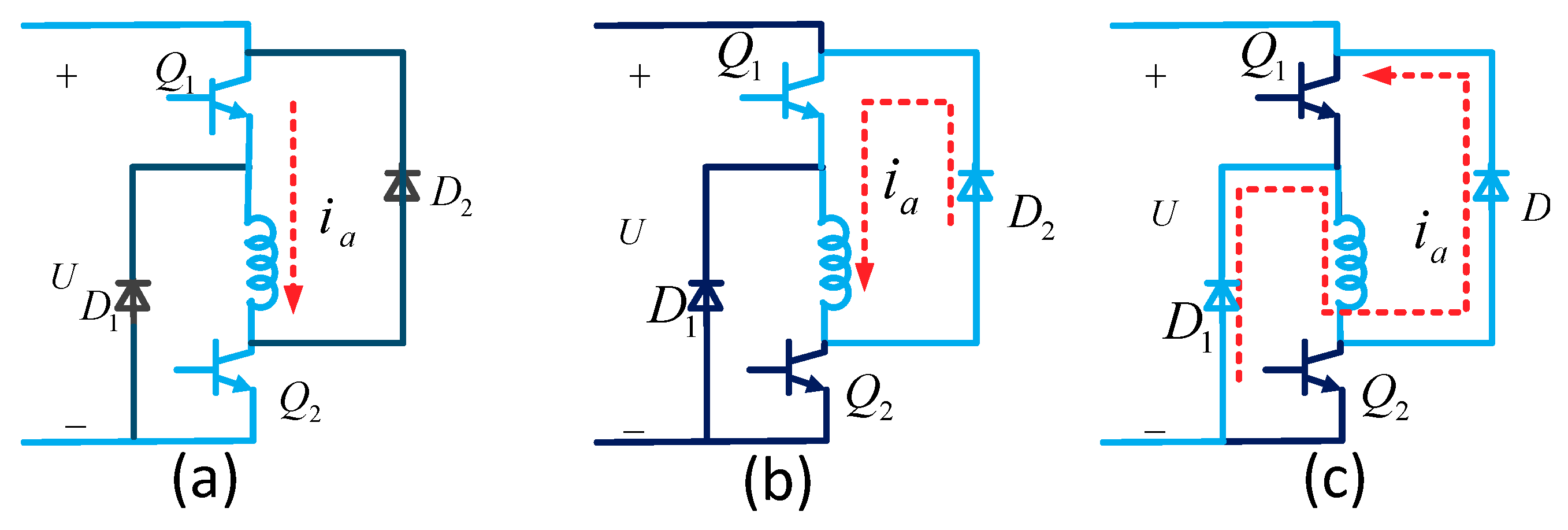
A variety of converters can be employed in the SRM drive. The asymmetric converter is generally used for suitable characteristics for independent current control. In this paper, the asymmetric converter is applied and three modes—the freewheeling, excitation, and demagnetization states modes—are adopted. The six switches work at turn-off and turn-on states independently. The three voltage states—zero voltage, positive voltage, and negative voltage—are exerted on the phase winding in sequence. Once both Q1 and Q2 are turned on, positive voltage is applied, the current is established immediately and the phase current flows through the windings, as is shown in Figure 2a. The phase torque increases as the inductance increases. At the commutation, for the outgoing phase, one of the switches is turned off and the other is kept open and the current decreases slightly, which is defined as the freewheeling mode, as shown in Figure 2b. The phase torque will be maintained for a short time and then reduced as the current drops. Sometimes, the accelerating rate of the descent is required. Then, both switches of a phase are turned off simultaneously, the polarity of the applied voltage is opposite to the direction of the current flow, and the energy deposit in the windings is fed back to the power supply side. This mode is defined as demagnetization and is shown in Figure 2c. The combination of the three states plays an important role in improving the current tracking ability and reducing the torque ripple. In the previous method, the switching frequency is fixed and the switch state only changes one time in a control cycle. Only the excitation and freewheeling modes are applied in the previous current control method, which is not suitable when the current descends sharply. In this paper, a combination of the three states is utilized, and the mode is chosen depending on the rate of current change.
3.3. Current Build-Up and Flat Flowing Region
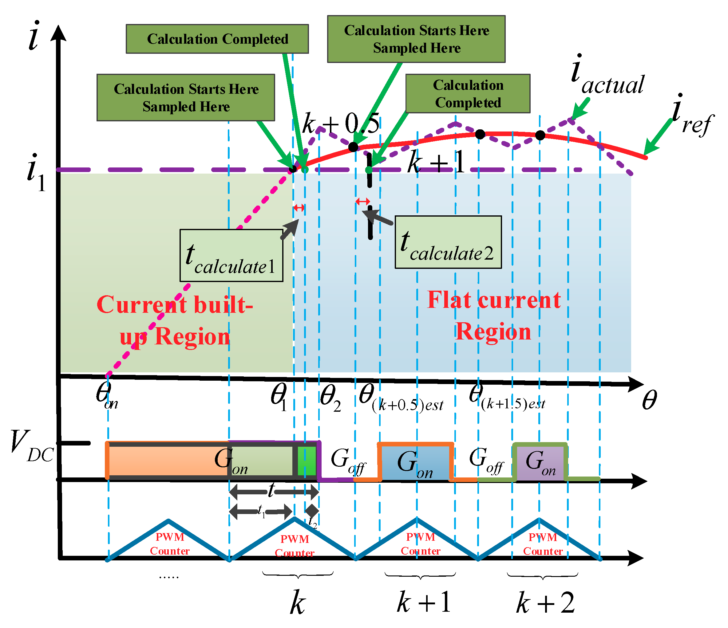
As observed from Figure 3, as the calculated voltage is applied on the phase, the current reaches the reference value at the angle θ1. The actual current will not be able to rise to a given value within a control cycle under a large reference current change rate. In the first few control cycles, the switching device is fully open and the voltage duty ratio is set to 100%. In the final control cycle, the duty ratio is divided into two parts. One part ensures that the actual current rises to the reference current at θ1, and the other part ensures that the actual current is equal to the reference current at the estimated position θ(k+0.5)est. θ2 is defined as the position where the freewheeling mode is activated. Since the PWM frequency is sufficiently high, the change in the rotational speed is ignored since the rotational speed change rate is very small compared with the current change rate. The speed is taken as a constant value. The estimated position at moment (k + 0.5) can be obtained.
To ensure the equation of the actual current and reference current at moment (k + 0.5), the demanded voltage in a control cycle can be derived by the following equation:
Then, the duty ratios can be precisely obtained. In the expression, the resistive drop is the average value of the reference value at θ(k+0.5)est, is the flux linkage at position θ(k+0.5)est where the current value is iref(k+0.5)est and ψ(θk,i1) is the flux linkage at position θk when the current value is equal to i1.
The PWM period is defined as . When the algorithm is implemented in a digital signal processor, the time spent in the calculation process is more or less equal to that of the PWM period. As a result, the computation time should not be ignored. The choice of the starting point of sampling is important since the PWM counter has a great impact on predictive current control. In [41], the calculation is performed during the current PWM cycle, and then, the calculated results are updated in the next PWM cycle. The use of the kth instant sampling values to calculate the duty ratio at instant (k + 1) will inevitably lead to errors. The exerted voltage in cycle k must be subtracted in cycle (k + 1). The sampling instant and starting point of the control algorithm calculation also need to be disposed of properly. In this paper, this compensation is not required. The time needed to complete the voltage calculations is no more than half of the PWM period, which is easy to know through the use of the counter. The sampling point is set to be the same as the starting point of the PWM counter count. The predictive control algorithm is executed simultaneously. After the calculation is completed, the calculated result is updated in the same PWM cycle. To make a smooth transition between the current build-up and flat flowing region, the actual current should be equal to the reference current at θ1 and θ(k+0.5)est. To facilitate the calculation, the time spent for excitation at the kth cycle is divided into two parts. Several control cycles, which are expressed as (k − 1)Tcycle, are used before the actual current reaches the given value at θ1. Then, the time spent for excitation before θ1 can be calculated as follows:
The immediate load mode is applied in the Time-Base Period Shadow Register, and the register value can be updated immediately. tcalculate is the time needed to finish the calculations, which can be obtained using the counter in the DSP. The freewheeling mode is not applied before θ1. Hence, the calculation time should be addressed properly.
At the flat current region, the required voltage applied to the interval in the (k + 1)th cycle is calculated based on the flux linkage method in the following equation:
where iref(k+1.5) is the current reference at instant (k + 1), i(k+0.5) is the actual current sampled at instant k, R is the phase resistance, ψ(θ(k+1.5),iref(k+1.5)) is the flux linkage at position θ(k+1.5)est with the current value iref(k+1.5)est, ψ(θ(k+0.5),i(k+0.5)) is the flux linkage at position θ(k+0.5)est with the current value iref(k+1.5)est, and Tcycle is the PWM period; the resistive drop is the average of the actual current sampled at instant k and the reference current at instant (k + 1.5). The duty ratio can be deduced by the following formula:
3.4. Region of Descending Current
Using the TSF method, especially the linear TSF method, the reference current sometimes decreases sharply and the actual current is not able to trace the reference current via the excitation PWM control strategy. To solve this problem, the demagnetization mode is employed. The prediction based on the flux linkage mode is also suitable for the negative voltage prediction. For the excitation mode, the duty ratio calculation is finished within a PWM control cycle and the calculation time needs to be further abstracted in the next cycle.
Compared with the predictive method in the excitation mode, the negative voltage prediction method is further improved in this paper. The calculation is performed at the freewheeling state. Therefore, the voltage that is calculated can be directly applied to phase winding without subtracting the previous voltage, which is exerted during the calculation. As shown in Figure 4, the negative voltage is exerted and it is necessary to calculate the duty radio separately.
Once the duty ratio D1 and D2 calculations finish, the PWM is updated immediately. Duty ratio D1 is applied, and all of the switches of the conduction phase are turned off; the motor operation transits from the freewheeling state to the demagnetization state. When this mode finishes, one of the switches is turned on and the motor operates at the freewheeling state; negative voltage is immediately exerted again. As the reference current profile varies over large ranges, the control mode should be switched flexibly between the freewheeling mode, excitation and demagnetization state depending on the reference current profile in the different control cycles.
3.5. Operation of the Asymmetric Converter
When the current descends sharply, the excitation-freewheeling mode needs to be transformed to the demagnetization-freewheeling mode to make the actual current reach the reference current. The details of the process is described in Figure 5. The angle and flux linkage is derived similarly in the current flat region.
The flux linkage and reference current at instants k and (k + 1.5) are easily obtained using the λ-i-θ characteristics of the machine mentioned above. Both the positive-zero and negative-zero voltage modes are switched when the current decreases or increases sharply. Similarly,
Since the prediction calculation finishes in the freewheeling mode, there is no need to take the calculating time into account. At instant (k + 1.5), the actual current decreases slowly and the actual current may reach point A instead of B. The influence of the error between the actual current and reference current is finite and will be eliminated in the following control cycle since the sampling current at instant (k + 1.5) is adopted in the duty ratio prediction. As observed in the figure, to make sure the actual current reached the reference value exactly at instant (k + 2) when the reference current decreases sharply, it is necessary to employ the demagnetization-freewheeling mode in the following cycle. The angle at instant (k + 1.5) is easy to be deduced. The flux linkage and reference current at instant , instant (k + 1.5) and instant (k + 2) can be acquired. It should be noted that the flux linkage deduced at instant (k + 1.5) uses the actual sampling current instead of the reference current. Suppose that the calculation finishes at point C. The current at point C is almost not changed compared with the current at point B since the time spent on the calculation is very short. The sampled current and flux linkage at instant (k + 1.5) can be used to predict the duty ratio of cycle (k + 2). The voltage exerted at (k + 2) can be calculated by the following equation:
It should be noted that the enhanced pulse width modulation (EPWM) register is set with the immediate execution mode. Once the calculation finishes, the PWM can be updated immediately.
3.6. Communication Region
Figure 6 shows the process of the predictive current control strategy when the motor is operated in the commutation region. To compel the actual current to reach the reference current at instant (k + 1), the applied voltage in the (k + 1)th control cycle is calculated at the kth control cycle.
When the current passes point (k + 1), three situations occur. One condition is that the reference current profile (as shown by the blue line in Figure 7) descends with a gentle slope; the actual current is controllable and the duty ratio is predicted similarly using the method at the current flat region. The applied voltage at (k + 1) is easy to calculate. Another condition is that the current descends sharply (as shown by the red line in Figure 7), which the actual current cannot track properly. In this situation, one switch device is turned off and the demagnetization mode is employed, in which the duty ratio is set to 100%. The third possibility is that the reference current profile (shown by the black line in the Figure 7) descends with a sharp slope and a higher demagnetization voltage is demanded. This condition will be studied in the following research.
4. Analysis of the Simulation and Experimental Results
The nameplate values of the SRM are shown with the following table. The number of stator/rotor poles, rated speed, rated voltage, and phase resistance are found in Table 1.
The three-phase 12/8 SRM experimental system was built. Phase current was acquired by using a high-precision ETCR035AD current sensor (ETCR, Guangzhou, China), the reference rotor position was obtained by using the Tamagawa TS2660N141E64 rotary transformer (Tamagawa, Iida, Japan), and AU6802E chip (Tamagawa, Iida, Japan) was used to decode the cosine signal of the position chip. The Specification of controller is shown in Table 2. Parameters of the switched reluctance motor (SRM) in the simulation is shown in Table 3.
The details of the simulation program are added in the simulation.
4.1. Simulation Results and Analysis
To assess the effectiveness of the current predictive control method, simulations are carried out under different types of TSFs, different types of TSFs, including linear TSF, cube TSF and other optima TSF, are chosen with the consideration of the rate of the current change, the capability of the power converter, and other factors. To prove the proposed current tracing method is effective in different TSFs, the comparisons with simulation results and experimental results are demonstrated in the paper. The results of the current tracking error and torque errors are displayed. The proposed and conventional current control methods are compared in terms of their current tracing ability and torque ripples. The sampling time is essential for tracking the current performance due to the limitation of the digital implementation. The torque ripples index is also impacted by the sampling time. To decrease the effect and make a fair comparison between the Simulink and the experiment, the Simulink sampling time is set to 100 µs, which is identical to the experiment. The torque ripples are also influenced by the current hysteresis band and overlapping angle. Therefore, the overlapping angle is set to the same angle in the simulation. The current hysteresis band is set to 0.1 A. Considering the linear magnetic effect and magnetic saturation, the torque command is set as 3.7 N·m and 8 N·m, respectively.
The traditional hysteresis control method based on a cube TSF is shown in Figure 8a. The Simulink sampling time is set as 100 µs, the band is set as 0.1 A, and the torque reference is set as 3.7 N·m. Obviously, the actual current cannot track the reference current accurately. When the maximum current error exceeds 6 A and the torque error between the reference current and actual current is as large as 2 N·m, the torque ripple is close to 51%. The performance of both the current and torque tracking abilities are improved when the sampling time increases, which is shown in Figure 9.
The simulation results indicate that the maximum current error and torque error are 0.8 A and 0.7 N·m, respectively. Compared with the case in which the sampling time is set as 100 µs, the error is reduced to a certain extent. The torque ripple is reduced to 23.2%, but is still at a high level, and the 10 µs control period is impractical in the application due to the limitation of IGBTs, especially under the heavy load condition.
In summary, the actual current is unable to trace the reference properly under traditional hysteresis current control. This problem will be improved using the proposed current control strategy. The actual current is able to trace the reference current using the proposed method, as shown in Figure 10. The maximum current error is reduced to 0.2 A. Thus, the torque ripples are reduced and the current is changed sharply at the commutation. The maximum torque error is 0.2 N·m. The torque ripples of the linear TSF at 300 r/min with the proposed control method reach 4%, which is much lower than that with the hysteresis current control method.
To fully validate the effectiveness of the proposed method for different TSFs, another type of linear TSF is also applied in this paper. The current tracking error and torque error using the CCC method are shown in Figure 11. The phase current error and torque error are 1.7 A and 1.1 N·m, respectively. The torque ripple reaches 25%, which is slightly higher than that of the cube TSF. The main reason for this difference is that the rate of change of the current for the linear TSF is larger than that for the cube TSF, which shows that the torque ripples are still large after employing the current hysteretic control approach, no matter which shape of the TSF is chosen.
The result of the simulation for the linear TSF using the proposed method is demonstrated in Figure 12. It is observed that the current tracking performance is very good, even under the condition in which the rate of change of the current is large. The phase error and torque error are 0.3 A and 0.4 N·m, respectively. It is clear that the current and torque tracking performance are much higher than those of the hysteresis control method. It should be noted that the ratio of the current change for the linear TSF is larger than that of the cubic TSF at the commutation region. There is slightly lower current error and torque error compared with those of using the cube TSF.
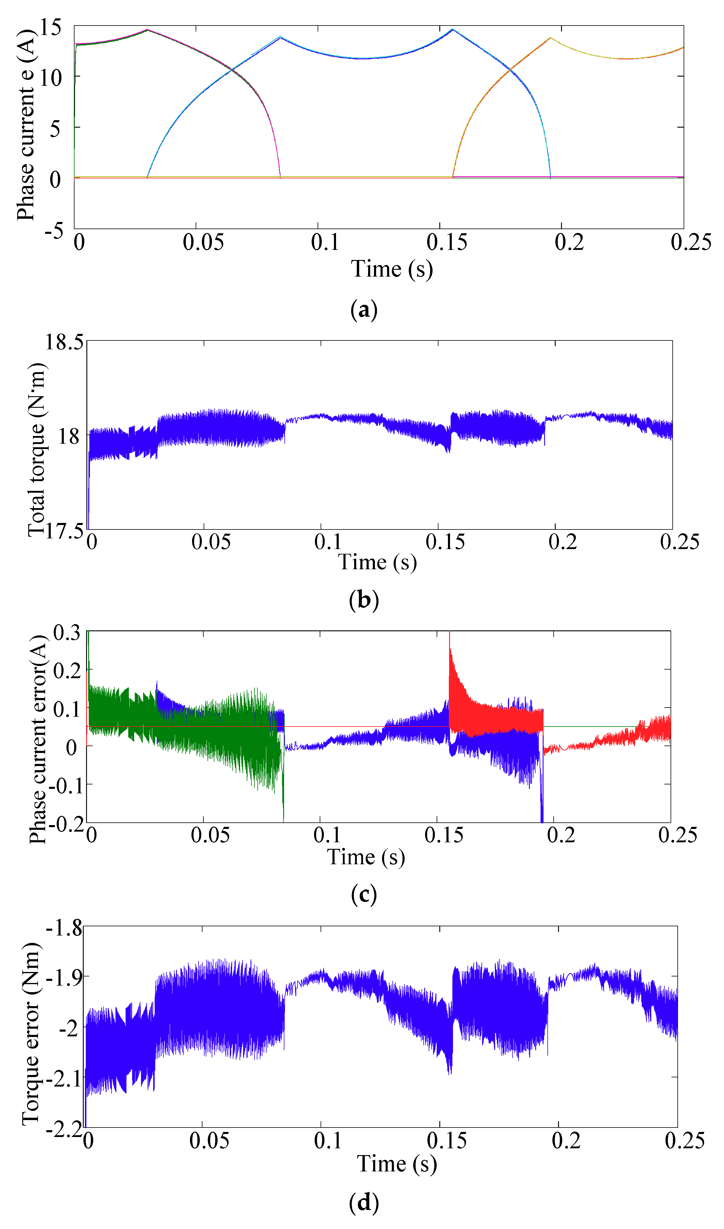
To verify the performance of the proposed method in the magnetic saturated region, the torque reference is set to 18 N·m in the simulation. As shown in Figure 13, the phase currents are able to precisely track their references. The phase error and torque error are 0.3 A and 0.25 N·m, respectively. The torque ripples increased to 5.4%, which is slightly larger than that in the linear magnetic region. However, compared with the CCC method, the current error and torque error are lower, and its performance for torque ripples is improved. In the terms of the RSM current, the performance is also slightly improved by employing the proposed method compared with the hysteresis current control method since the current is precisely controlled and the current is not overshot under the same condition.
According to the Simulink results, the phase currents are able to successfully track the reference using the proposed current predictive method. The torque ripples of the linear TSF at 300 r/min with the hysteresis current control method are 28.6%, which is higher than those with the proposed current predictive method. The Root-Mean-Square (RMS) current is obviously reduced. Therefore, the feasibility of the proposed current predictive method is theoretically verified.
It is shown that there is a slight difference in terms of the average torque by applying the traditional hysteresis current control method and proposed method. However, with the development of the proposed current optimized control strategies, the torque ripple is low and is expected to reach 0.04 using the linear TSF and 0.054 using the cube TSF.
4.2. Experimental Results
The simulation results should be verified further experimentally. To verify the feasibility of the proposed current predictive scheme, a 12/8 motor is used. Further details of the SRM parameters are described in Table 3. The phase current is obtained using a high precision current sensor. An asymmetric half-bridge converter is employed to drive the motor. The rotor position is acquired by the rotary transformer, and the position signal is decoupled through the AU6802E chip in the experiment. The turn-on angle and overlap angle are set as 0°and 55° (electrical angle), respectively. It should be noted that the SRM parameters in the simulation are slightly different from the experimental SRM parameters, but the feasibility is not affected.
The current profile with the conventional current hysteresis control method is depicted in Figure 14a. Both the duty ratio and switching frequency are fixed as 40% and 10 kHz, respectively, in the method. When the motor is operated at a low speed, the back electromotive force is negligible. Obviously, the current variations are large, especially in the low inductance region, and the currents even reach 6.3 A during the sampling period. However, the current variation shown in Figure 14b is much smaller than that shown in Figure 14a.
The torque sharing functions (TSFs) are divided into the linear TSF and cube TSF, which are traditionally applied to reduce the torque ripple. The current hysteresis control method is usually used in TSFs, and the current variations are large. As a result, the current hysteresis control method will inevitable give rise to torque ripples.
It is noted that the current ripple is large in Figure 15a, which is about 75%. In Figure 15a, the torque ripple reach to 92%.
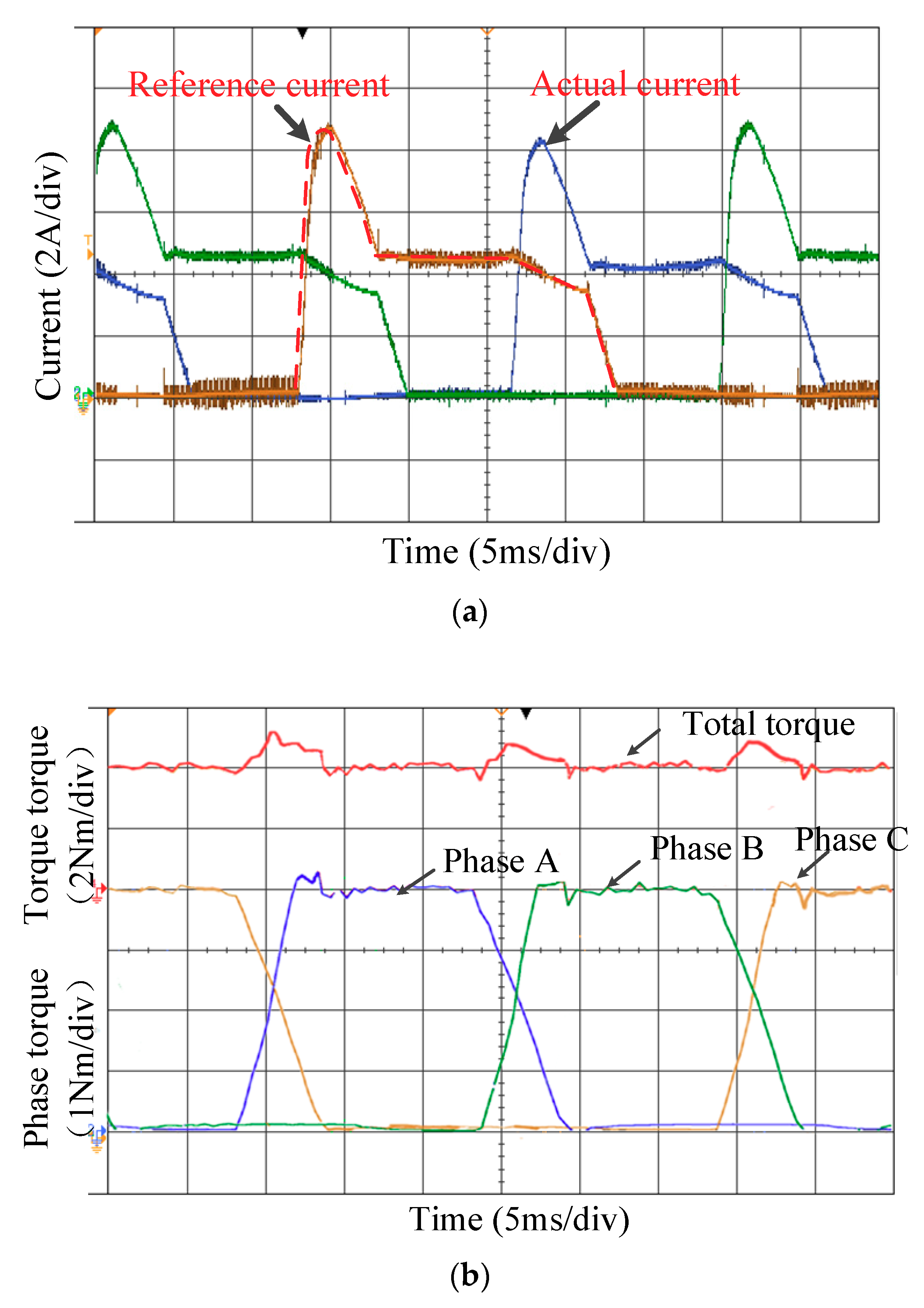
As is shown in Figure 16, the proposed current predictive control leads to lower current ripples and torque ripples compared with the conventional current hysteresis control. The current variation is small and the torque ripples caused by the current tracking error are approximately 1.8%, which is far lower than those of using the CCC method. The torque ripple at the un-commutation region is about 7.5%. The maximum torque ripples occur in the commutation region, approximately 15%. The main reason for the torque ripples is that the overlap angle and turn-on angle are not accurately calculated according the current and speed. The performance will be improved by optimizing the overlap angle.
To verify the feasibility of using the proposed predictive current scheme for different TSFs, the proposed method is employed in the cube TSF in the experiment. As shown in Figure 17a, the actual current is able to trace the reference current as precisely as the linear TSF. For linear TSF and cube TSF, the torque ripple at the un-commutation region similar, which is about 7%. The maximum torque ripples 25% appear commutation region, which is a bit higher than that using the linear TSF. The primary reason is that the performance in terms of torque ripple is prone to be deteriorated by the parameter angle-on and angle-off.
The magnetic saturation condition is taken into account in the experiment. During magnetic saturation, the rate of change of the reference currents diminishes since the back EMF increases when the current is at a high level. The motor operates at magnetic saturation when the reference torque reaches 8 N·m in the same way that the current and torque can track the reference value accurately, as described in Figure 18. The torque ripples in the commutation region increase to 15% because the overlap angle is not adjusted when the reference torque changes since the overlap at the load is no longer suitable. The performance will be improved when the overlap angle is optimized. The torque ripples in the un-commutation region are as small as 2%. It is clear that the proposed method is also effective under magnetic saturation.
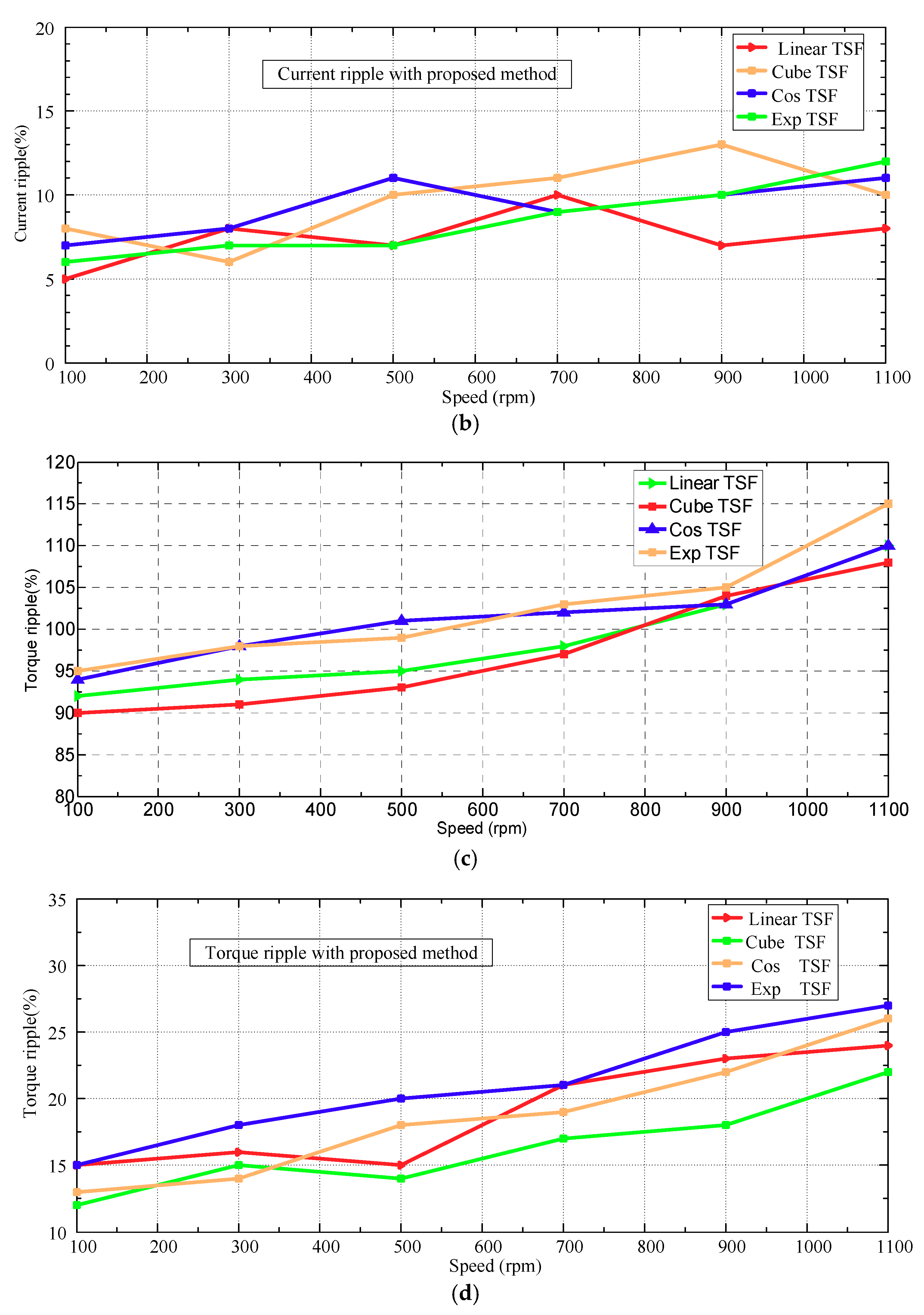
The compared results are demonstrated in Figure 19, it is shown that the proposed method is valid to reduce the current ripple and torque ripple obviously, it should be noted that the performance is effect by the speed. As the speed rise, the EMF should be taken into consideration, and the accuracy of the predictive current will be deteriorated by the inaccurate EMF. In addition, the sampling error for current is also a considerable factor.
In Figure 20a–c the RMS currents are 5.19 A, 5.72 A and 4.92 A at the 5 N·m, respectively. By comparing Figure 20a–c, it is clear that the RMS current of the proposed method is lower than that of the traditional CCC strategy since it has a better tracking ability. The RMS current increases with the reference torque, as shown in Figure 20d,e, to 27.3 A and 30.6 A at 18 N·m, respectively. The RMS current is still lower by 12% using the proposed method.
The torque is obtained via the torque sensor and converted from analog to digital through the AD converter. The experimental setup of the 12/8 SRM drive system is shown in Figure 21.
5. Suggested Improvements and Future Direction of this Work
Firstly, both of the switching devices are turned off and full negative voltage is exerted on the windings during a control period when the current profile descends very sharply. In case the actual current is still cannot trace the reference current, a higher demagnetization voltage is demanded. Similarly, it is existing for the ascending sharply condition, higher excitation voltage is required. How to enhance the voltage fast enough is an issue to be studied in the future research. In addition, it should be noted that the proposed predictive method is also effective for other TSFs and better results will be acquired when the TSFs are amended accordingly and optimized. Finally, the torque ripple can be reduced further by choosing a proper turn-on and turn-off angle. However, the result is local optimal rather than global minimal. This problem can be improved by automatic optimization.
6. Conclusions
In this paper, a novel current control scheme with optimized PWM is proposed to reduce current ripple and torque ripple. Based on the feature of the reference current profile, three running regions including current build-up region, flat flowing region and descending region are divided. To promote the tracing precision and improve the dynamic tracking performance for current, freewheel, excitation and demagnetization are chosen flexible and the voltage ratio duty is predicted accurately according to the information of the running motor. Compared with the conventional current chopping control, the proposed current control method can make the actual current trace the reference current more precisely, the maximum error is within 10%, much lower than that using the traditional current copper control scheme. For SRM, torque and current have the corresponding mapping characteristics, it is well known that the current control is significantly to the torque control, high precision current inevitable contributes to the torque reduction, the high precision for the current control is achieved in this paper. Another contribution for this paper is that the optimized PWM method is first adopted in the TSFs scheme. The torque ripple reduction strategy including linear TSF and cube TSF are employed. With the proposed current method, the torque has a better performance in terms of tracing ability, the torque ripple is reduced to about 20%. As well, the determination of the RMS current is investigated, and it is reduced by 12% in this paper. Finally, the simulation and experimental results demonstrate the effectiveness of the proposed method. The proposed current control method also can be employed in the DITC (Direct Instantaneous Torque Control) and other torque ripple minimization strategies in future.
Author Contributions
All the contributions in this paper are equally shared among the authors.
Funding
This research was funded by National Natural Science Foundation of China under Project 51407064 and 51577052.
Conflicts of Interest
The authors declare no conflicts of interest.
Appendix A
In the function, x is related to theta, y represents current, z denotes torque.
- Parameters c1, c2, c, kr[0.1,0.25], kf[0,1.0], k, xb[1/9.0,1/3.0], xe[7/9.0,1.0], x1[7/18.0,11.0/18.0];
- Variable x, y, z;
- ConstStr fs = 1 − kf × ((x − x1)2);
- ConstStr fr = kr × ((x/xb)(3/2));
- ConstStr ff = 1 − x25;
- ConstStr ff1 = (((1 − x)/(1 − xe))25)/(1 + (((1 − x)/(1 − xe))25));
- ConstStr L0p = k × (((x/xb)13) × fs + fr) × ff1/(1 + ((x/xb)13));
- ConstStr f = c1/(1 + c × ((x − xb)2)) + c2/(1 + c × ((x − xe)2));
- ConstStr f1 = f × ((x/xb)13)/(1 + ((x/xb)13));
- Function z = (0.5 × L0p × (y2))/((1 + f × (y3))(1/3));
where
- c1: 1.54202819947362 × 10⁻⁵
- c2: 0.000442753170130073
- c: 301.641864196729
- kr: 0.248303583528203
- kf: 0.999999999999997
References
- Jiang, J.W.; Bilgin, B.; Emadi, A. Three-Phase 24/16 Switched Reluctance Machine for a Hybrid Electric Powertrain. IEEE Trans. Transp. Electr. 2017, 3, 76–85. [Google Scholar] [CrossRef]
- Flieller, D.; Nguyen, N.K.; Wira, P.; Sturtzer, G.; Abdeslam, D.O.; Merckle, J. A Self-Learning Solution for Torque Ripple Reduction for Nonsinusoidal Permanent-Magnet Motor Drives Based on Artificial Neural Networks. IEEE Trans. Ind. Electron. 2014, 61, 655–666. [Google Scholar] [CrossRef] [Green Version]
- Bayless, J.; Kurihara, N.; Sugimoto, H.; Chiba, A. Acoustic Noise Reduction of Switched Reluctance Motor with Reduced RMS Current and Enhanced Efficiency. IEEE Trans. Energy Convers. 2016, 31, 627–636. [Google Scholar] [CrossRef]
- Wang, Y.; Hao, W. A Torque Impulse Balance Control for Multi-Tooth Fault Tolerant Switched-Flux Machines under Open-Circuit Fault. Energies 2018, 11, 1919. [Google Scholar] [CrossRef]
- Uddin, W.; Husain, T.; Sozer, Y.; Husain, I. Design Methodology of a Switched Reluctance Machine for Off-Road Vehicle Applications. IEEE Trans. Ind. Appl. 2016, 52, 2138–2147. [Google Scholar] [CrossRef]
- Quispe, M.; Chuchon, M.; Adriano, R.; Samaniego, J. Design and implementation of a low-cost prototype system for continuous monitoring of electric fields generated by mobile base stations in the 850 MHz and 1900 MHz frequency bands. IEEE Lat. Am. Trans. 2016, 14, 463–470. [Google Scholar] [CrossRef]
- Nezamabadi, M.M.; Afjei, E.; Torkaman, H. Design, Dynamic Electromagnetic Analysis, FEM, and Fabrication of a New Switched-Reluctance Motor with Hybrid Motion. IEEE Trans. Magn. 2016, 52, 1–8. [Google Scholar] [CrossRef]
- Chiba, A.; Kiyota, K.; Hoshi, N.; Takemoto, M.; Ogasawara, S. Development of a Rare-Earth-Free SR Motor with High Torque Density for Hybrid Vehicles. IEEE Trans. Energy Convers. 2015, 30, 175–182. [Google Scholar] [CrossRef]
- Yao, W.-S. Rapid Optimization of Double-Stators Switched Reluctance Motor with Equivalent Magnetic Circuit. Energies 2017, 10, 1603. [Google Scholar] [CrossRef]
- Pan, J.; Wang, W.; Zhang, B.; Cheng, E.; Yuan, J.; Qiu, L.; Wu, X. Complimentary Force Allocation Control for a Dual-Mover Linear Switched Reluctance Machine. Energies 2017, 11, 23. [Google Scholar] [CrossRef]
- Sanches, E.S.; Santisteban, J.A. Mutual Inductances Effect on the Torque of an Axial Magnetic Flux Switched Reluctance Motor. IEEE Lat. Am. Trans. 2015, 13, 2239–2244. [Google Scholar] [CrossRef]
- Mikail, R.; Husain, I.; Islam, M.S.; Sozer, Y.; Sebastian, T. Four-Quadrant Torque Ripple Minimization of Switched Reluctance Machine Through Current Profiling with Mitigation of Rotor Eccentricity Problem and Sensor Errors. IEEE Trans. Ind. Appl. 2015, 51, 2097–2104. [Google Scholar] [CrossRef]
- Kermanipour, M.J.; Ganji, B. Modification in Geometric Structure of Double-Sided Axial Flux Switched Reluctance Motor for Mitigating Torque Ripple. Can. J. Elect. Comput. Eng. 2015, 38, 318–322. [Google Scholar] [CrossRef]
- Shaked, N.T.; Rabinovici, R. New procedures for minimizing the torque ripple in switched reluctance motors by optimizing the phase-current profile. IEEE Trans. Magn. 2005, 41, 1184–1192. [Google Scholar] [CrossRef]
- Labiod, C.; Srairi, K.; Mahdad, B.; Benbouzid, M.E.H. A novel control technique for torque ripple minimization in switched reluctance motor through destructive interference. Electr. Eng. 2017, 100, 1–10. [Google Scholar] [CrossRef]
- Jin Woo, L.; Hong Seok, K.; Byung Il, K.; Byung Taek, K. New rotor shape design for minimum torque ripple of SRM using FEM. IEEE Trans. Magn. 2004, 40, 754–757. [Google Scholar]
- Sheth, N.K.; Rajagopal, K.R. Torque profiles of a switched reluctance motor having special pole face shapes and asymmetric stator poles. IEEE Trans. Magn. 2004, 40, 2035–2037. [Google Scholar] [CrossRef]
- Fahimi, B.; Emadi, A.; Sepe, R.B. A switched reluctance machine-based starter/alternator for more electric cars. IEEE Trans. Energy Convers. 2004, 19, 116–124. [Google Scholar] [CrossRef]
- Lee, D.H.; Lee, Z.G.; Liang, J.; Ahn, J.W. Single-Phase SRM Drive with Torque Ripple Reduction and Power Factor Correction. IEEE Trans. Ind. Appl. 2007, 43, 1578–1587. [Google Scholar] [CrossRef]
- Li, H.; Bilgin, B.; Emadi, A. An Improved Torque Sharing Function for Torque Ripple Reduction in Switched Reluctance Machines. IEEE Trans. Power Electron. 2018, 1. Available online: https://ieeexplore.ieee.org/abstract/document/8357897 (accessed on 11 May 2018). [CrossRef]
- Choi, Y.K.; Yoon, H.S.; Koh, C.S. Pole-Shape Optimization of a Switched-Reluctance Motor for Torque Ripple Reduction. IEEE Trans. Magn. 2007, 43, 1797–1800. [Google Scholar] [CrossRef]
- Xue, X.D.; Cheng, K.W.E.; Ho, S.L. Optimization and Evaluation of Torque-Sharing Functions for Torque Ripple Minimization in Switched Reluctance Motor Drives. IEEE Trans. Power Electron. 2009, 24, 2076–2090. [Google Scholar] [CrossRef] [Green Version]
- Lee, D.H.; Liang, J.; Lee, Z.G.; Ahn, J.W. A Simple Nonlinear Logical Torque Sharing Function for Low-Torque Ripple SR Drive. IEEE Trans. Ind. Electron. 2009, 56, 3021–3028. [Google Scholar] [CrossRef]
- Shin, H.-U.; Park, K.; Lee, K.-B. A Non-Unity Torque Sharing Function for Torque Ripple Minimization of Switched Reluctance Generators in Wind Power Systems. Energies 2015, 8, 11685–11701. [Google Scholar] [CrossRef] [Green Version]
- Ye, J.; Bilgin, B.; Emadi, A. An Offline Torque Sharing Function for Torque Ripple Reduction in Switched Reluctance Motor Drives. IEEE Trans. Energy Convers. 2015, 30, 726–735. [Google Scholar] [CrossRef]
- Fuengwarodsakul, N.H.; Menne, M.; Inderka, R.B.; Doncker, R.W.D. High-dynamic four-quadrant switched reluctance drive based on DITC. IEEE Trans. Ind. Appl. 2005, 41, 1232–1242. [Google Scholar] [CrossRef]
- Ye, J.; Bilgin, B.; Emadi, A. An Extended-Speed Low-Ripple Torque Control of Switched Reluctance Motor Drives. IEEE Trans. Power Electron. 2015, 30, 1457–1470. [Google Scholar] [CrossRef]
- Vujičić, V.P. Minimization of Torque Ripple and Copper Losses in Switched Reluctance Drive. IEEE Trans. Power Electron. 2012, 27, 388–399. [Google Scholar] [CrossRef]
- Han, G.; Chen, H.; Shi, X.; Wang, Y. Phase current reconstruction strategy for switched reluctance machines with fault-tolerant capability. IET Electr. Power Appl. 2017, 11, 399–411. [Google Scholar] [CrossRef]
- Gan, C.; Wu, J.; Wang, N.; Hu, Y.; Cao, W.; Yang, S. Independent Current Control of Dual Parallel SRM Drive Using a Public Current Sensor. IEEE/ASME Trans. Mechatron. 2017, 22, 392–401. [Google Scholar] [CrossRef] [Green Version]
- Dúbravka, P.; Rafajdus, P.; Makyš, P.; Szabó, L. Control of switched reluctance motor by current profiling under normal and open phase operating condition. IET Electr. Power Appl. 2017, 11, 548–556. [Google Scholar] [CrossRef]
- Kusumi, T.; Hara, T.; Umetani, K.; Hiraki, E. Simple control technique to eliminate source current ripple and torque ripple of switched reluctance motors for electric vehicle propulsion. In Proceedings of the IECON 2016—42nd Annual Conference of the IEEE Industrial Electronics Society, Florence, Italy, 23–26 October 2016; pp. 1876–1881. [Google Scholar]
- Ahmad, S.S.; Narayanan, G. Linearized Modeling of Switched Reluctance Motor for Closed-Loop Current Control. IEEE Trans. Ind. Appl. 2016, 52, 3146–3158. [Google Scholar] [CrossRef]
- Dong-Hee, L.; JongHeon, L.; Jin-Woo, A. Current control of a high speed SRM with an advanced 4-level converter. In Proceedings of the 2011 IEEE 8th International Conference on Power Electronics and ECCE Asia (ICPE & ECCE), Jeju, Korea, 30 May–3 June 2011; pp. 109–114. [Google Scholar]
- Peng, F.; Ye, J.; Emadi, A. A Digital PWM Current Controller for Switched Reluctance Motor Drives. IEEE Trans. Power Electron. 2015, 31, 7087–7098. [Google Scholar] [CrossRef]
- Gan, C.; Wu, J.; Sun, Q.; Yang, S.; Hu, Y.; Jin, L. Low-cost direct instantaneous torque control for switched reluctance motors with bus current detection under soft-chopping mode. IET Power Electron. 2016, 9, 482–490. [Google Scholar] [CrossRef]
- Ye, J.; Malysz, P.; Emadi, A. A Fixed-Switching-Frequency Integral Sliding Mode Current Controller for Switched Reluctance Motor Drives. IEEE J. Emerg. Sel. Top. Power Electron. 2015, 3, 381–394. [Google Scholar]
- Chai, J.Y.; Liaw, C.M. Reduction of speed ripple and vibration for switched reluctance motor drive via intelligent current profiling. IET Electr. Power Appl. 2010, 4, 380–396. [Google Scholar] [CrossRef]
- Li, X.; Shamsi, P. Model Predictive Current Control of Switched Reluctance Motors with Inductance Auto-Calibration. IEEE Trans. Ind. Electron. 2016, 63, 3934–3941. [Google Scholar] [CrossRef]
- Li, X.; Shamsi, P. Inductance Surface Learning for Model Predictive Current Control of Switched Reluctance Motors. IEEE Trans. Transp. Electrification 2015, 1, 287–297. [Google Scholar] [CrossRef]
- Mikail, R.; Husain, I.; Sozer, Y.; Islam, M.S.; Sebastian, T. A Fixed Switching Frequency Predictive Current Control Method for Switched Reluctance Machines. IEEE Trans. Ind. Appl. 2014, 50, 3717–3726. [Google Scholar] [CrossRef]
- Lin, C.-K.; Yu, J.-T.; Huang, H.-Q.; Wang, J.-T.; Yu, H.-C.; Lai, Y.-S. A Dual-Voltage-Vector Model-Free Predictive Current Controller for Synchronous Reluctance Motor Drive Systems. Energies 2018, 11, 1743. [Google Scholar] [CrossRef]
- Hui, C.; Li, M.; Hui, W.; Shen, S.Q.; Wang, W. Torque ripple minimization for switched reluctance motor with predictive current control method. In Proceedings of the 2017 20th International Conference on Electrical Machines and Systems (ICEMS), Sydney, Australia, 11–14 August 2017; pp. 1–4. [Google Scholar]
- Méndez, S.; Martínez, A.; Millán, W.; Montaño, C.E.; Pérez-Cebolla, F. Design, Characterization, and Validation of a 1-kW AC Self-Excited Switched Reluctance Generator. IEEE Trans. Ind. Electron. 2014, 61, 846–855. [Google Scholar] [CrossRef]
Figure 1.
Block diagram of torque sharing function (TSF) based on the proposed current control method.
Figure 1.
Block diagram of torque sharing function (TSF) based on the proposed current control method.
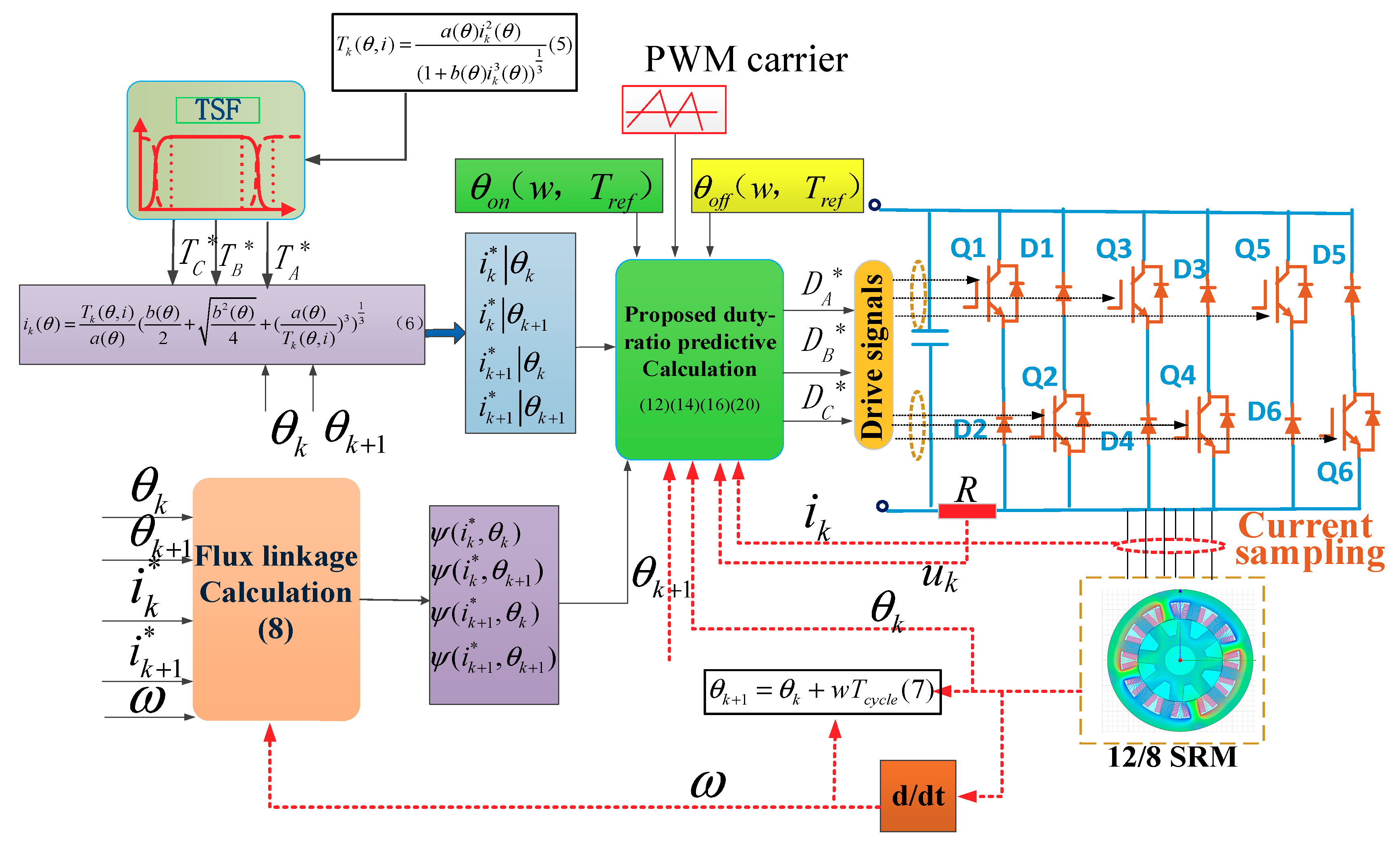
Figure 2.
Three modes include (a) excitation, (b) freewheeling, and (c) demagnetization.

Figure 3.
Duty ratio predicted at current build-up and flat flowing.

Figure 4.
Duty ratio predicted at current descending region. PWM: pulse width modulation.
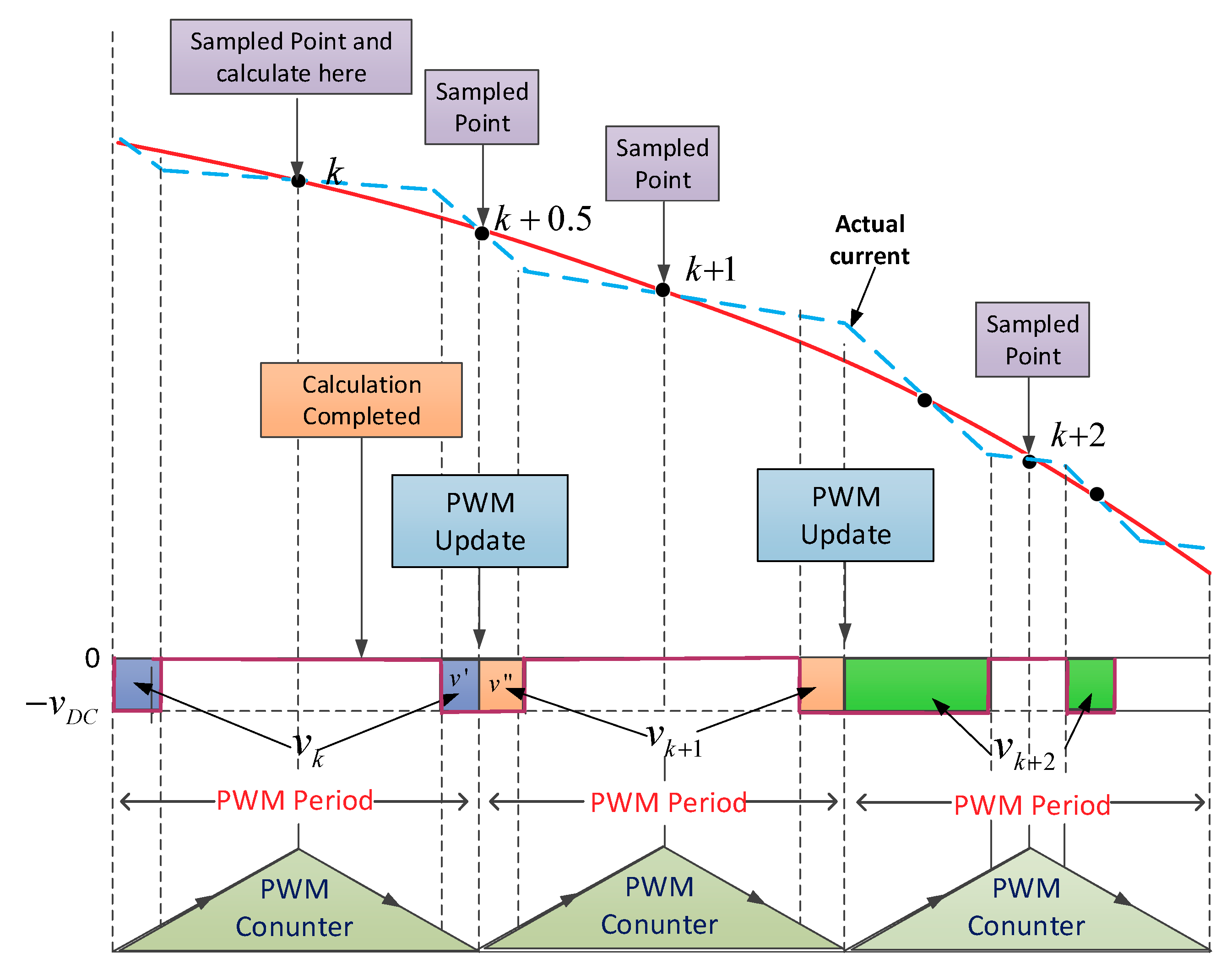
Figure 5.
Duty ratio predicted at Transformation from excitation-freewheeling mode to demagnetization-freewheeling mode.
Figure 5.
Duty ratio predicted at Transformation from excitation-freewheeling mode to demagnetization-freewheeling mode.
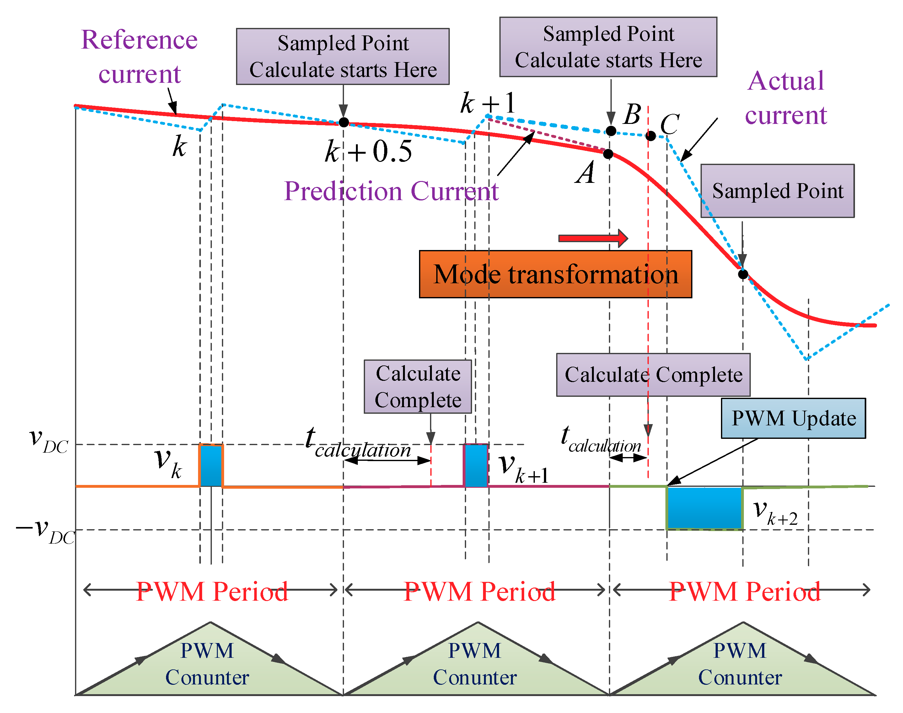
Figure 6.
Duty ratio predicted at communication region.

Figure 7.
Three possibilities of current control at the commutation.
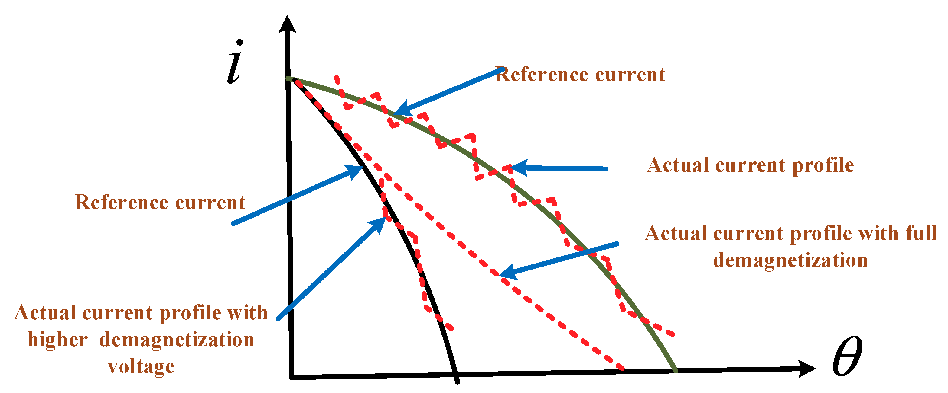
Figure 8.
Simulation result when with current chopping control (CCC) method based on cube TSF (band is set 0.1, reference torque is set 3.7 N·m and sample time is set 100 μs). (a) Profiles of phase current and its reference (b) Total torque (c) Phase torque (d) Phase current error.
Figure 8.
Simulation result when with current chopping control (CCC) method based on cube TSF (band is set 0.1, reference torque is set 3.7 N·m and sample time is set 100 μs). (a) Profiles of phase current and its reference (b) Total torque (c) Phase torque (d) Phase current error.
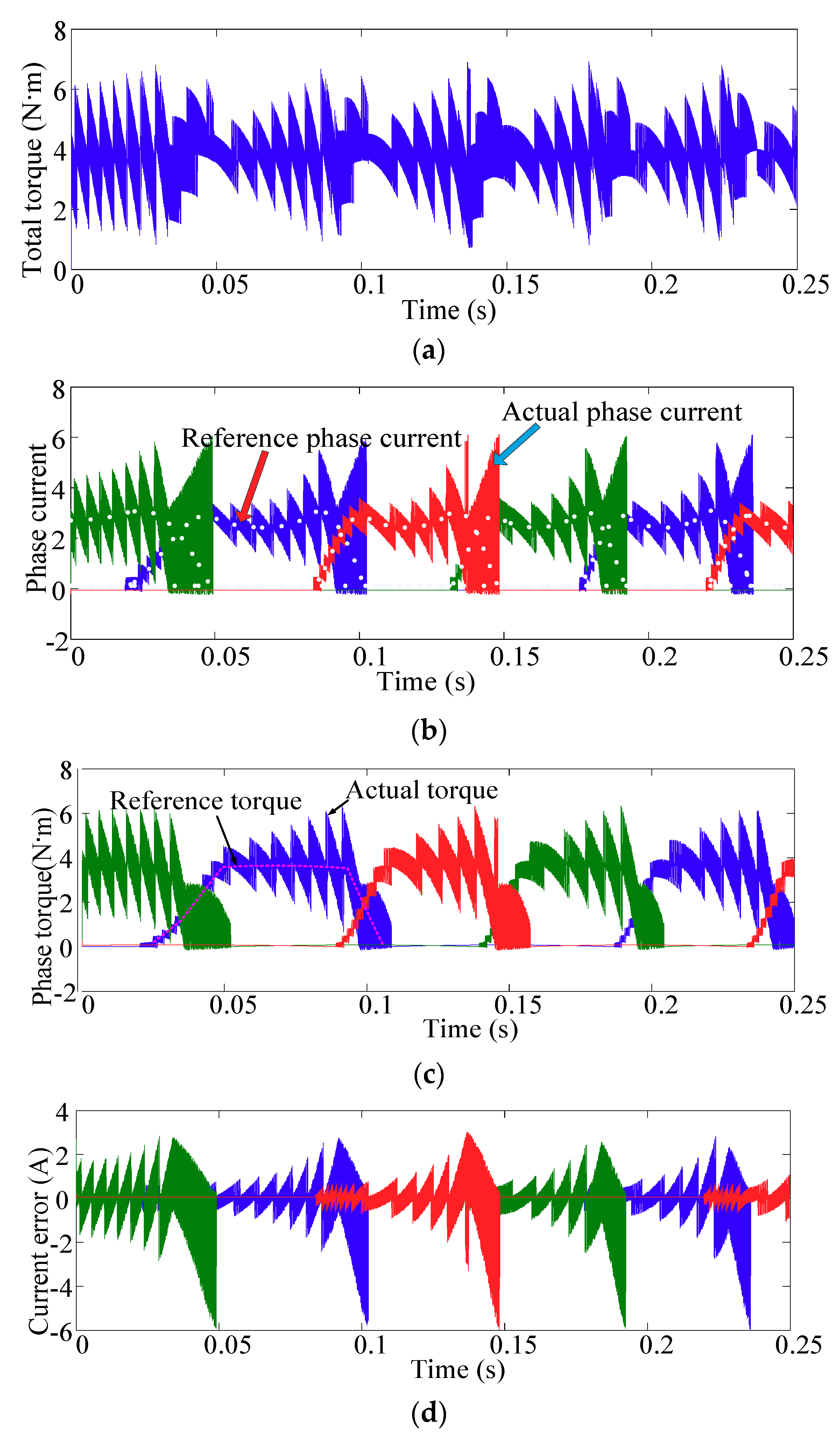
Figure 9.
Simulation results when using current chopping control (CCC) method based on cube TSF (band is set 0.1, reference torque is set 3.7 N·m and sample time is set 1 × 10⁻⁵ s). (a) Profiles of phase current and its reference (b) Total torque (c) Phase torque (d) Phase current error (e) Torque error.
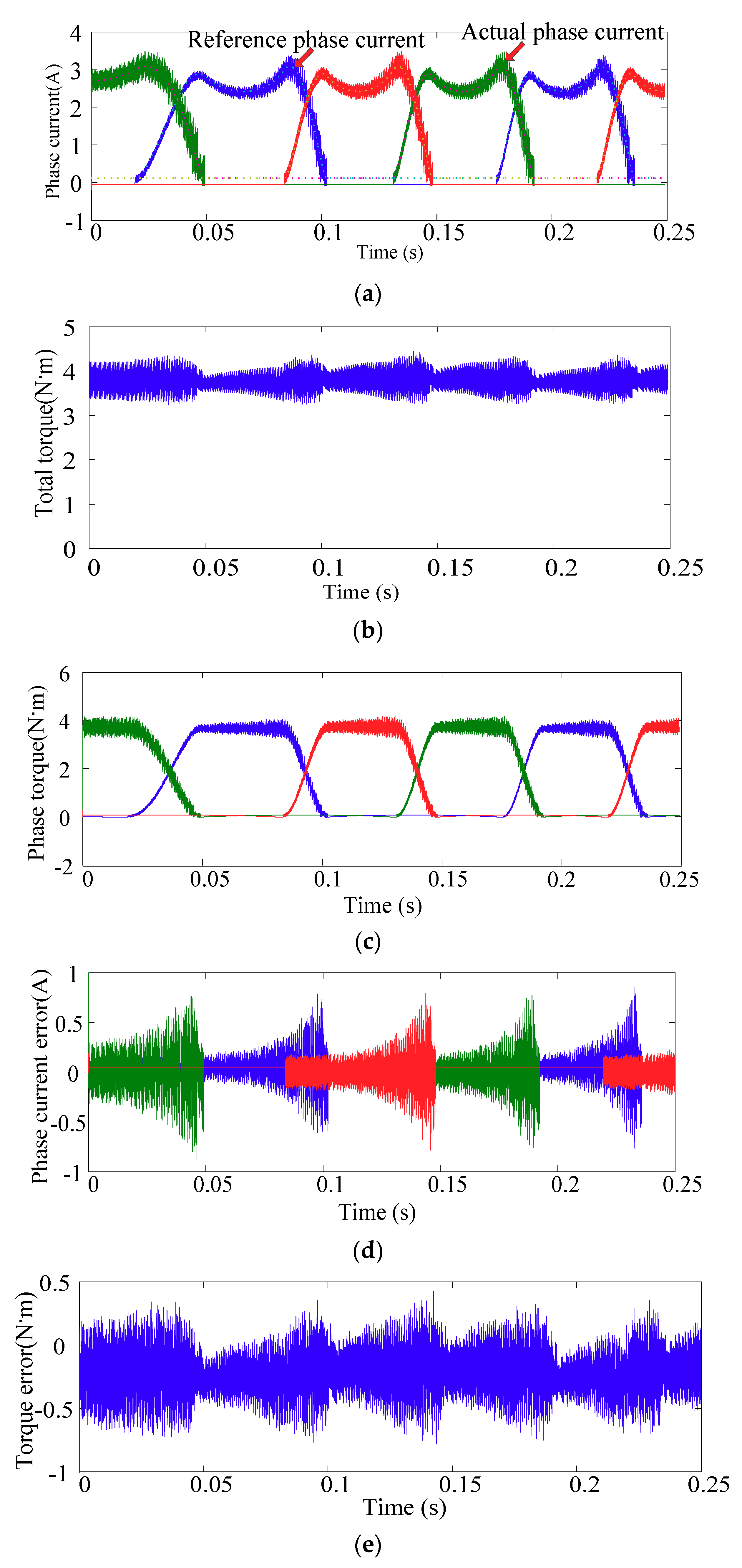
Figure 10.
Simulation result when using predictive current method based on cube TSF (reference torque is set 3.7 N·m and sample time is set 1 × 10⁻⁴ s). (a) Profiles of phase current and its reference (b) Total torque (c) Phase torque (d) Phase current error.
Figure 10.
Simulation result when using predictive current method based on cube TSF (reference torque is set 3.7 N·m and sample time is set 1 × 10⁻⁴ s). (a) Profiles of phase current and its reference (b) Total torque (c) Phase torque (d) Phase current error.
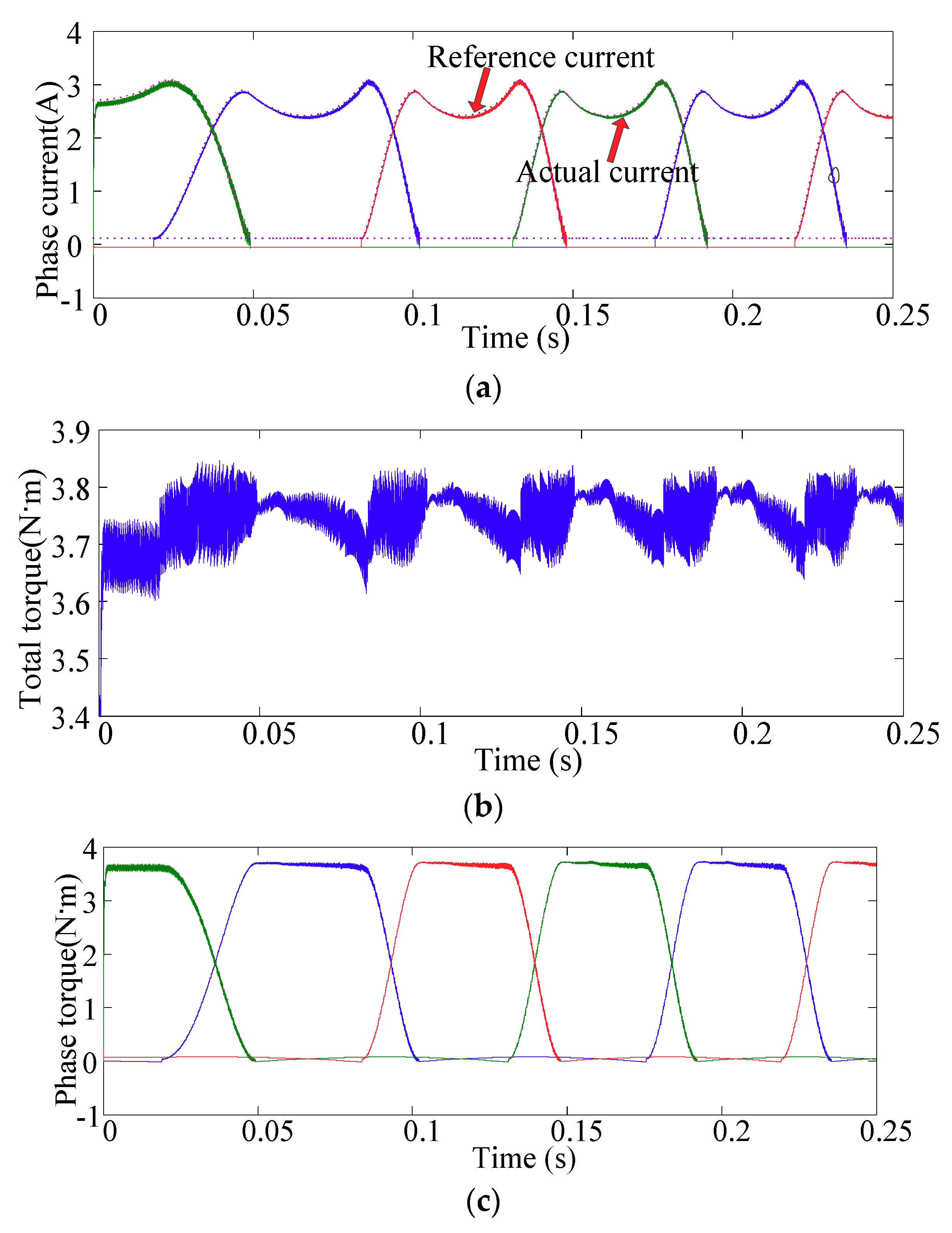
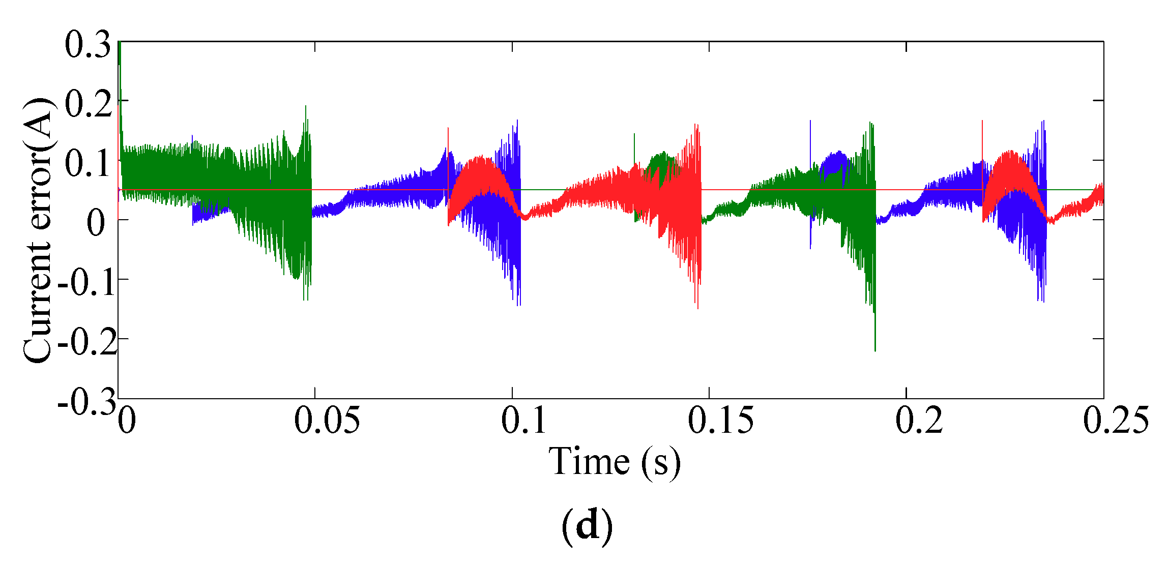
Figure 11.
Simulation results when using CCC method based on linear TSF (band is set 0.1, reference torque is set 3.7 N·m and sample time is set 1 × 10⁻⁵ s), (a) Phase current error (b) Torque error.
Figure 11.
Simulation results when using CCC method based on linear TSF (band is set 0.1, reference torque is set 3.7 N·m and sample time is set 1 × 10⁻⁵ s), (a) Phase current error (b) Torque error.
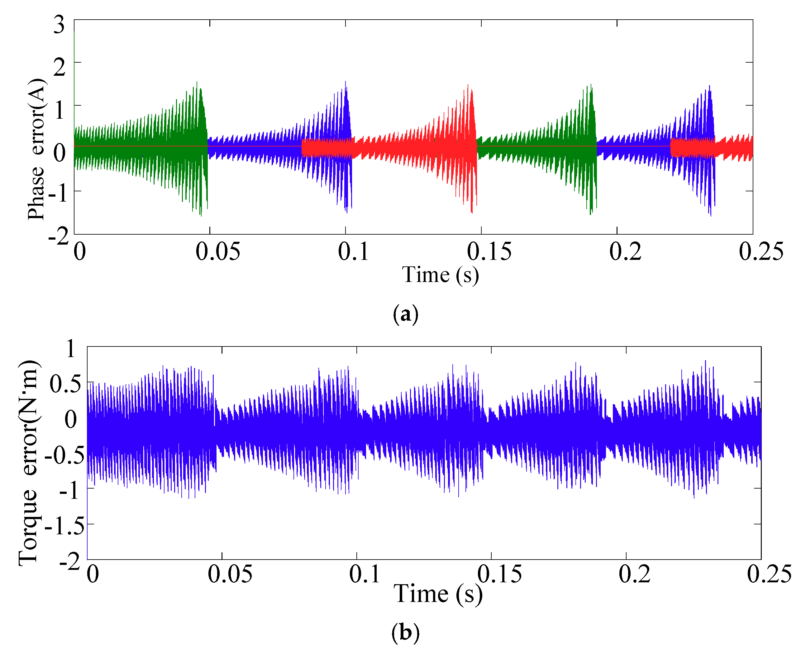
Figure 12.
Simulation results when using predictive current method based on linear TSF (reference torque is set 3.7 N·m and sample time is set 1 × 10⁻⁵ s). (a)Phase current error (b) Profiles of phase current and its reference (c) Torque error.
Figure 12.
Simulation results when using predictive current method based on linear TSF (reference torque is set 3.7 N·m and sample time is set 1 × 10⁻⁵ s). (a)Phase current error (b) Profiles of phase current and its reference (c) Torque error.
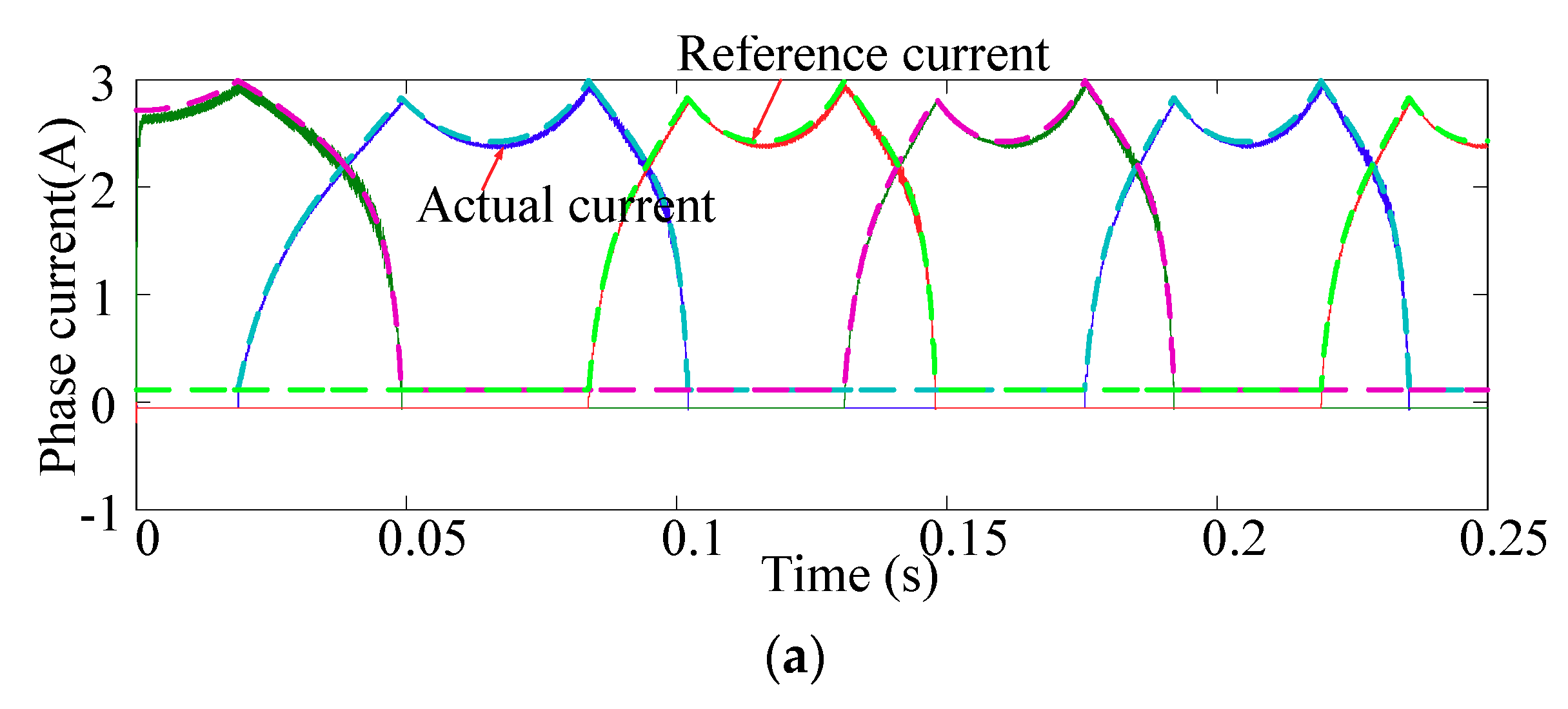
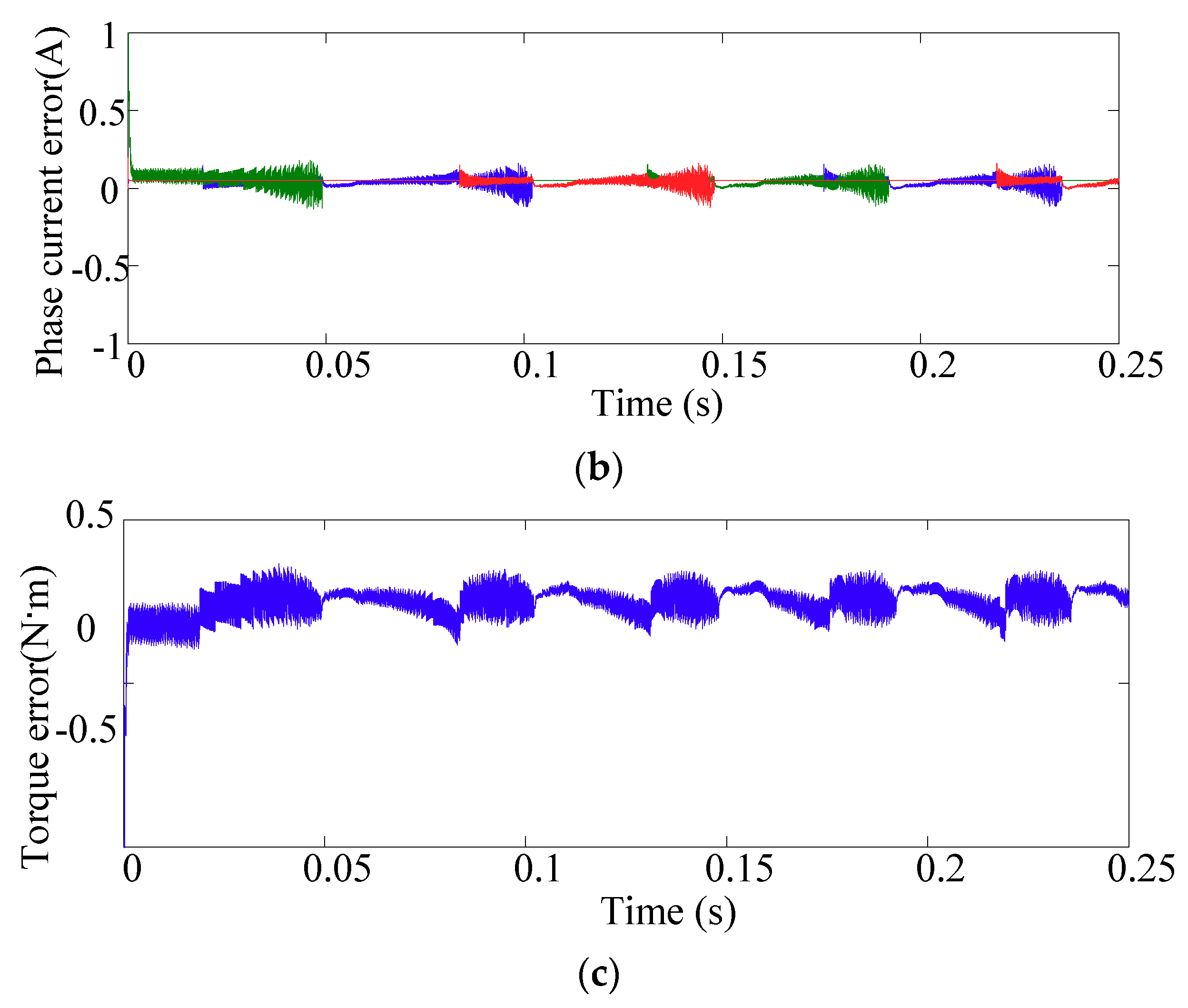
Figure 13.
Simulation results when using the predictive current method based on the linear TSF (the reference torque is set to 18 N·m, and the sample time is set to 1 × 10⁻⁵ s). (a) Profiles of the phase current and its reference (b) total torque, (c) phase current error, and (d) torque error.
Figure 13.
Simulation results when using the predictive current method based on the linear TSF (the reference torque is set to 18 N·m, and the sample time is set to 1 × 10⁻⁵ s). (a) Profiles of the phase current and its reference (b) total torque, (c) phase current error, and (d) torque error.

Figure 14.
Experimental results. (a) Conventional current hysteresis control (the hysteresis band is 0.1 A, the reference is 4 A, and the switching frequency is 10 KHz) and (b) the proposed current control switching method (Frequency = 10 KHz).
Figure 14.
Experimental results. (a) Conventional current hysteresis control (the hysteresis band is 0.1 A, the reference is 4 A, and the switching frequency is 10 KHz) and (b) the proposed current control switching method (Frequency = 10 KHz).
Figure 15.
Experiment results with conventional current hysteresis control (hysteresis band is 0.1 A) based on linear TSF (a) Current profile (b) Phase torque profile and total torque profile.
Figure 15.
Experiment results with conventional current hysteresis control (hysteresis band is 0.1 A) based on linear TSF (a) Current profile (b) Phase torque profile and total torque profile.
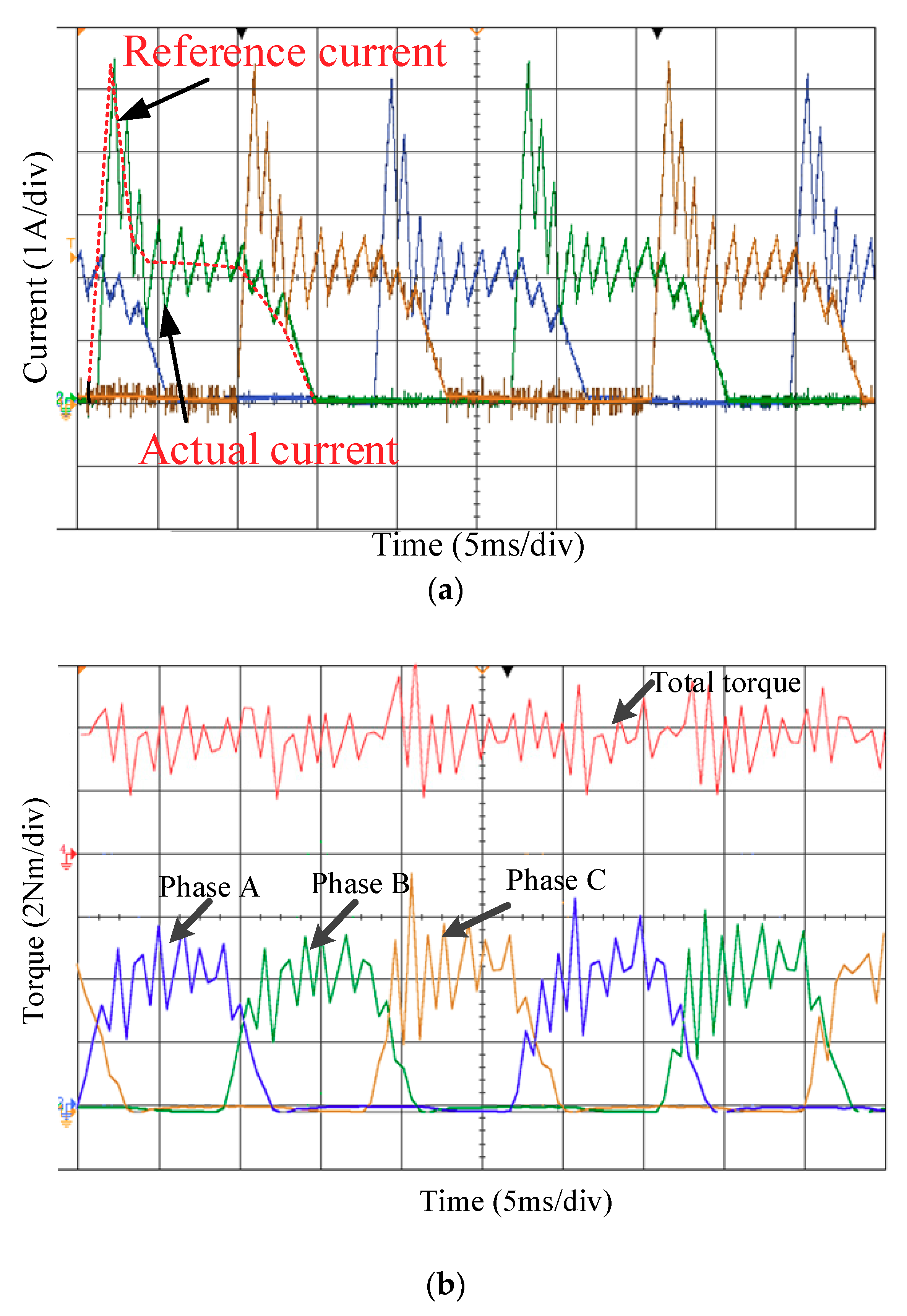
Figure 16.
Experiment results with predictive current control method based on linear TSF when the reference torque is set 4 N·m (a) Current profile (b) Phase torque and Total torque.
Figure 16.
Experiment results with predictive current control method based on linear TSF when the reference torque is set 4 N·m (a) Current profile (b) Phase torque and Total torque.

Figure 17.
Experiment results with predictive current control method based on cube TSF when the reference torque is set 4 N·m (a) Current profile (b) Phase torque and total torque.
Figure 17.
Experiment results with predictive current control method based on cube TSF when the reference torque is set 4 N·m (a) Current profile (b) Phase torque and total torque.
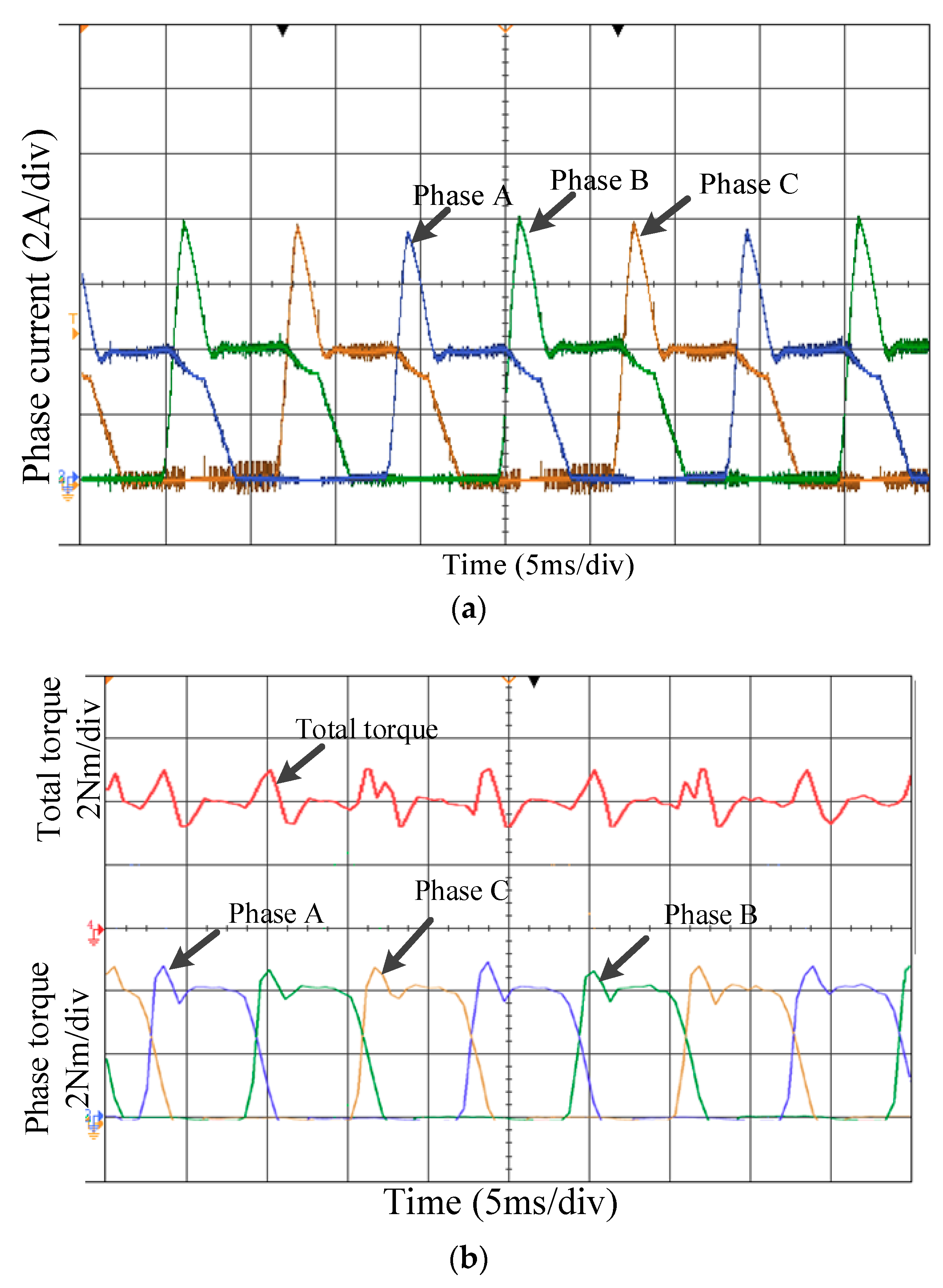
Figure 18.
Experiment results with current predictive control based on cube TSF at 100 r/min. (a) Current profile (b) Phase torque and total torque profiles.
Figure 18.
Experiment results with current predictive control based on cube TSF at 100 r/min. (a) Current profile (b) Phase torque and total torque profiles.
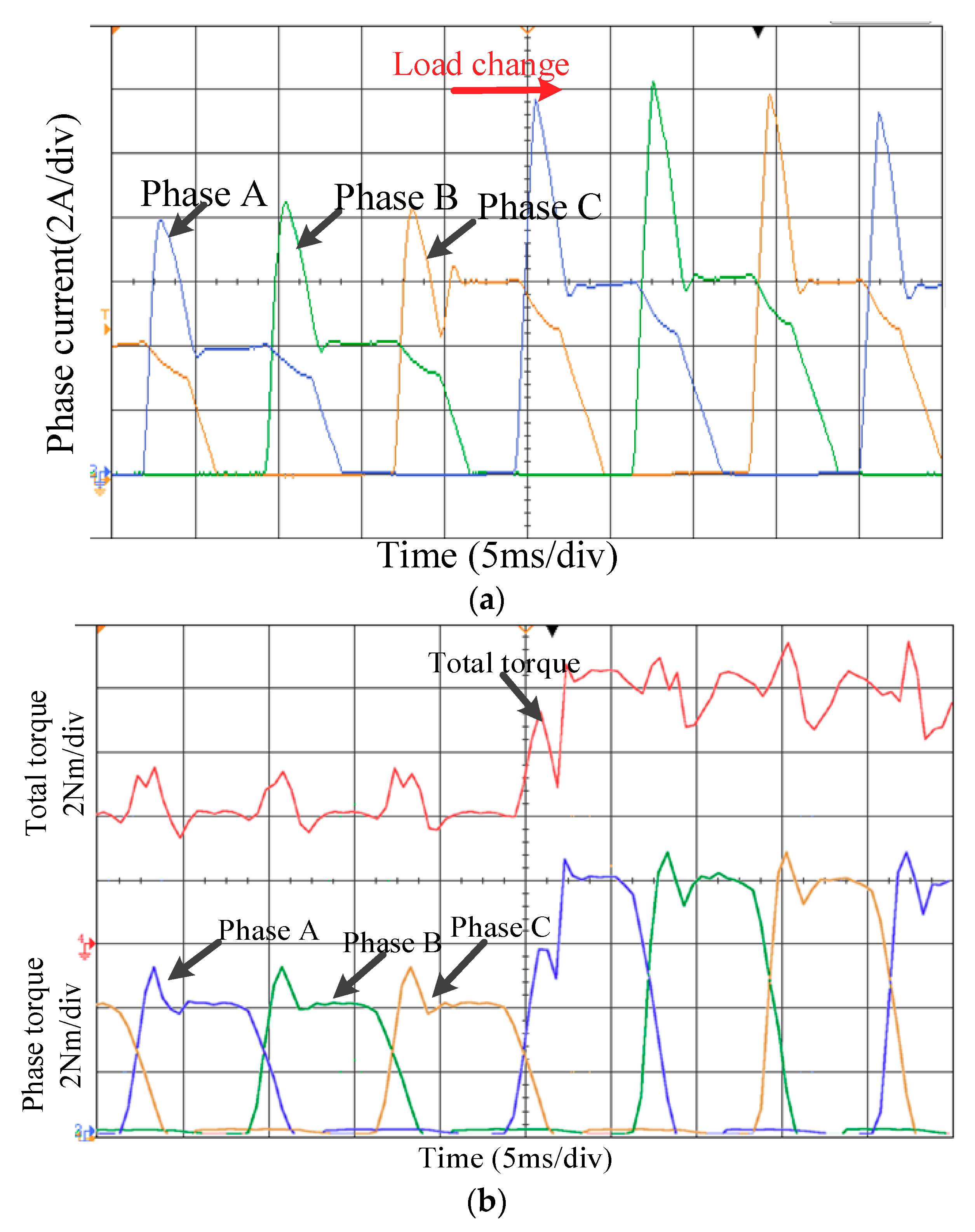
Figure 19.
Current ripple and torque ripple with different method. (a) current ripple under CCC (b) torque ripple under CCC (c) current ripple under proposed method (d) torque ripple under proposed method.
Figure 19.
Current ripple and torque ripple with different method. (a) current ripple under CCC (b) torque ripple under CCC (c) current ripple under proposed method (d) torque ripple under proposed method.


Figure 20.
Root-Mean-Square (RMS) results with different methods.
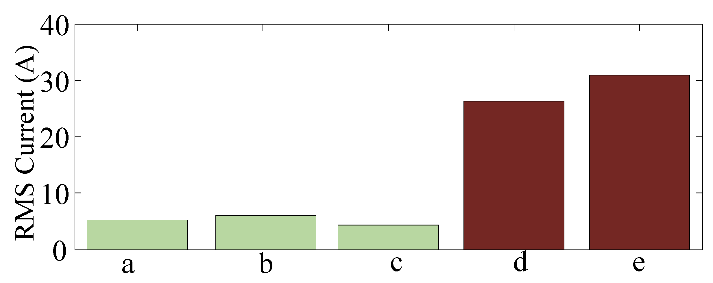
Figure 21.
Experimental setup of the 12/8 SRM drive system.


Table 1.
Specification of SRM.
| Number of stator/rotor poles | 12/8 |
| Rated speed | 1190 r/min |
| Rated power | 5.5 kW |
| Rated voltage | 200 V |
| Phase resistance | 200 V |
| Type of silicon steel sheet | 50 w270 |
Table 2.
Specification of controller.
| DSP | TMS320F28335 |
| Torque transducer | JN338 |
| Magnetic power brake | FZ-J |
| DC power supply | KD-200A |
| Converter | Asymmetric half-bridge |
| Current sensor | ETCR035AD |
| Rotary transformer | TS2660N141E64 |
Table 3.
Parameters of the switched reluctance motor (SRM) in the simulation.
| Poles | 12/8 |
| Aligned inductance | 0.5 × 10⁻³ H |
| Unaligned inductance | 0.14 × 10⁻³ H |
| Saturated aligned inductance | 400 A |
| Maximum current | 0.14 × 10⁻³ H |
| Maximum flux linkage | 0.472 V·s |
| Stator resistance | 0.01 Ohm |
| Inertia | 0.022 kg·m2 |
© 2018 by the authors. Licensee MDPI, Basel, Switzerland. This article is an open access article distributed under the terms and conditions of the Creative Commons Attribution (CC BY) license (http://creativecommons.org/licenses/by/4.0/).
Share and Cite
MDPI and ACS Style
Cai, H.; Wang, H.; Li, M.; Shen, S.; Feng, Y.; Zheng, J. Torque Ripple Reduction for Switched Reluctance Motor with Optimized PWM Control Strategy. Energies 2018, 11, 3215. https://doi.org/10.3390/en11113215
AMA Style
Cai H, Wang H, Li M, Shen S, Feng Y, Zheng J. Torque Ripple Reduction for Switched Reluctance Motor with Optimized PWM Control Strategy. Energies. 2018; 11(11):3215. https://doi.org/10.3390/en11113215
Chicago/Turabian StyleCai, Hui, Hui Wang, Mengqiu Li, Shiqi Shen, Yaojing Feng, and Jian Zheng. 2018. "Torque Ripple Reduction for Switched Reluctance Motor with Optimized PWM Control Strategy" Energies 11, no. 11: 3215. https://doi.org/10.3390/en11113215
Note that from the first issue of 2016, this journal uses article numbers instead of page numbers. See further details here.