Smart Global Maximum Power Point Tracking Controller of Photovoltaic Module Arrays
Abstract
:1. Introduction
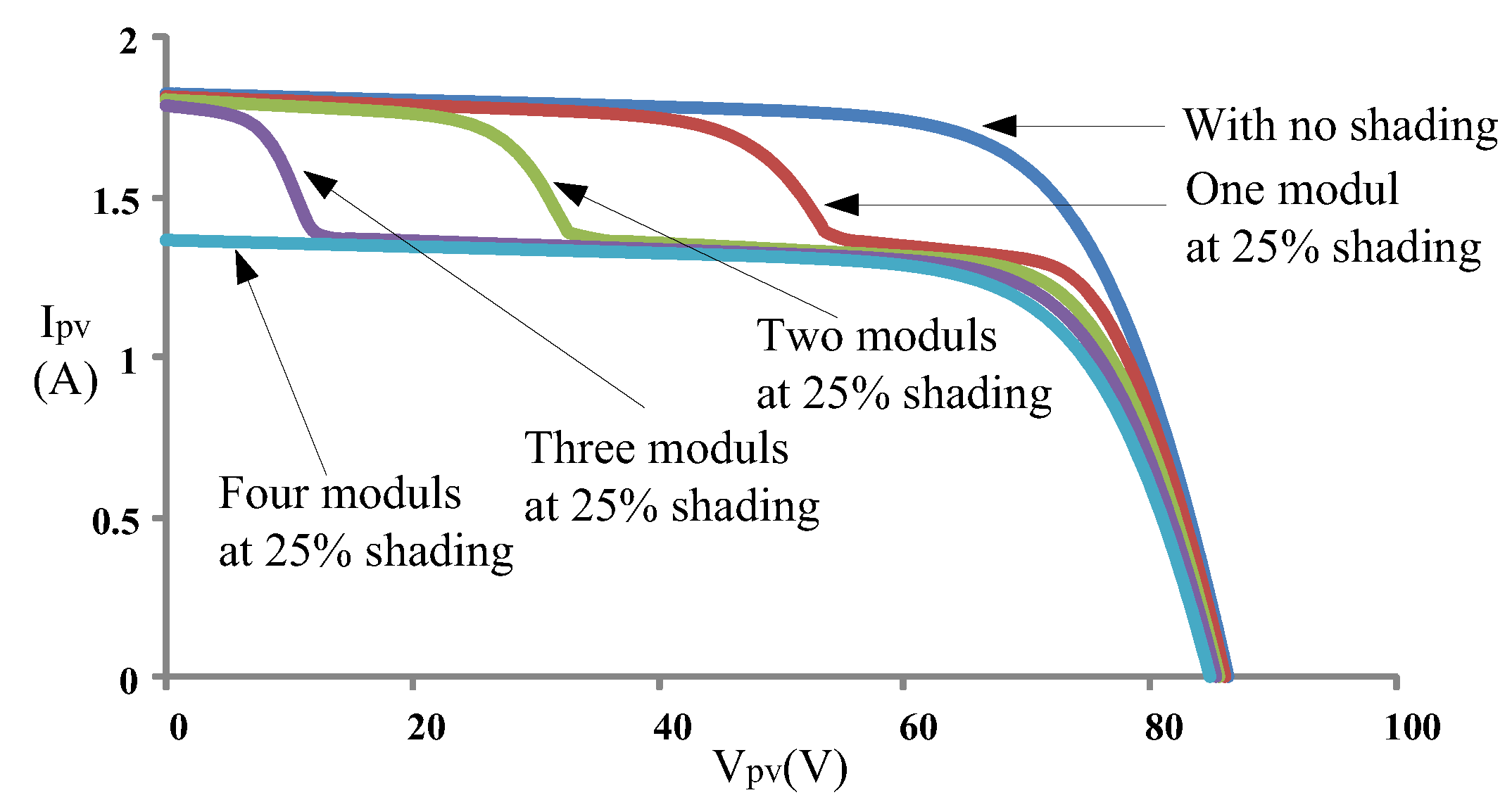
2. Characteristics of Photovoltaic Module Array
3. Particle Swarm Optimization
3.1. Conventional Particle Swarm Optimization
- Step 1
- Configure the number of particles, maximum number of iterations, weighting value, and learning factors.
- Step 2
- Initialize the particle swarm and randomly configure the location and velocity of each particle.
- Step 3
- Substitute the initial location of each particle into an objective function to assess the fitness function value of each particle.
- Step 4
- Compare the fitness function value of each particle with its individual optimal memory location (Pbest,i) to select the more favorable value to update Pbest.
- Step 5
- Compare each Pbest value with the group optimal memory value (Gbest); if a Pbest value is more favorable than the Gbest value, the Gbest value is updated to the Pbest value.
- Step 6
- Use the kernel equations of PSO to update the particle velocity and location, as shown in Equations (1) and (2).
- Step 7
- Terminate the tracking process if the stop criterion is fulfilled. Otherwise, repeat Step 4 to 6 until fulfilling the stop criterion (identifying the global optimal solution) or researching the maximum iteration.
- Weighting value W: The W value of a particle is associated with its previous movement distance.
- Cognition learning factor (C1): The C1 value of a particle is related to itself.
- Social learning factor (C2): The C2 value of a particle is related to other particles.
- : the velocity of ith particle in jth iteration.
- : the location of ith particle in jth iteration.
- rand1(): the first random number generator, the value of which is between 0 and 1.
- rand2(): the second random number generator, the value of which is between 0 and 1.
- : the individual optimal solution of ith particle.
- : the group optimal solution.
3.2. Modified Particle Swarm Optimization
- (1)
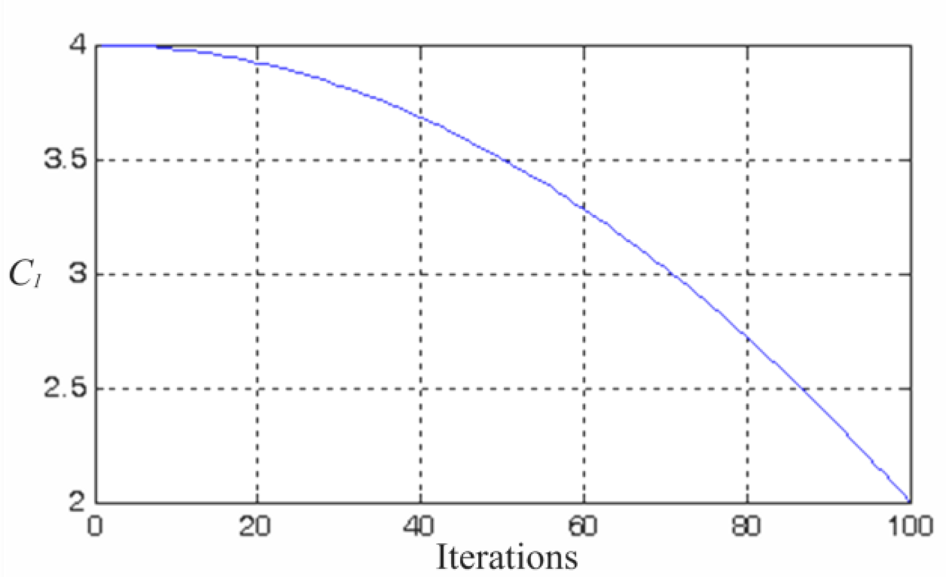
- m > 0 and a positive value indicate that the particles lie to the left of the maximum power point, with the tracking direction toward the maximum power point. A large m value implies that the particles are far away from the maximum power point; hence, the weighting value is increased to accelerate the tracking speed.
- (2)
- m < 0 and a positive value indicate that the particles lie to the right of the maximum power point, with the tracking direction toward the maximum power point. A small m value implies that the particles far away from the maximum power point; hence, the weighting value is increased to accelerate the tracking speed.
- : the current number of iterations.
- : the maximum number of iterations.
- P(j+1): the power yielded through j + 1 iterations.
- V(j+1): the voltage yielded through j + 1 iterations.
- C1,max: upper limit of cognition learning factor.
- C1,min: lower limit of cognition learning factor.
- C2,max: upper limit of social learning factor.
- C2,min: lower limit of social learning factor.
3.3. Framework of the Maximum Power Point Tracker of Modified Particle Swarm Optimization
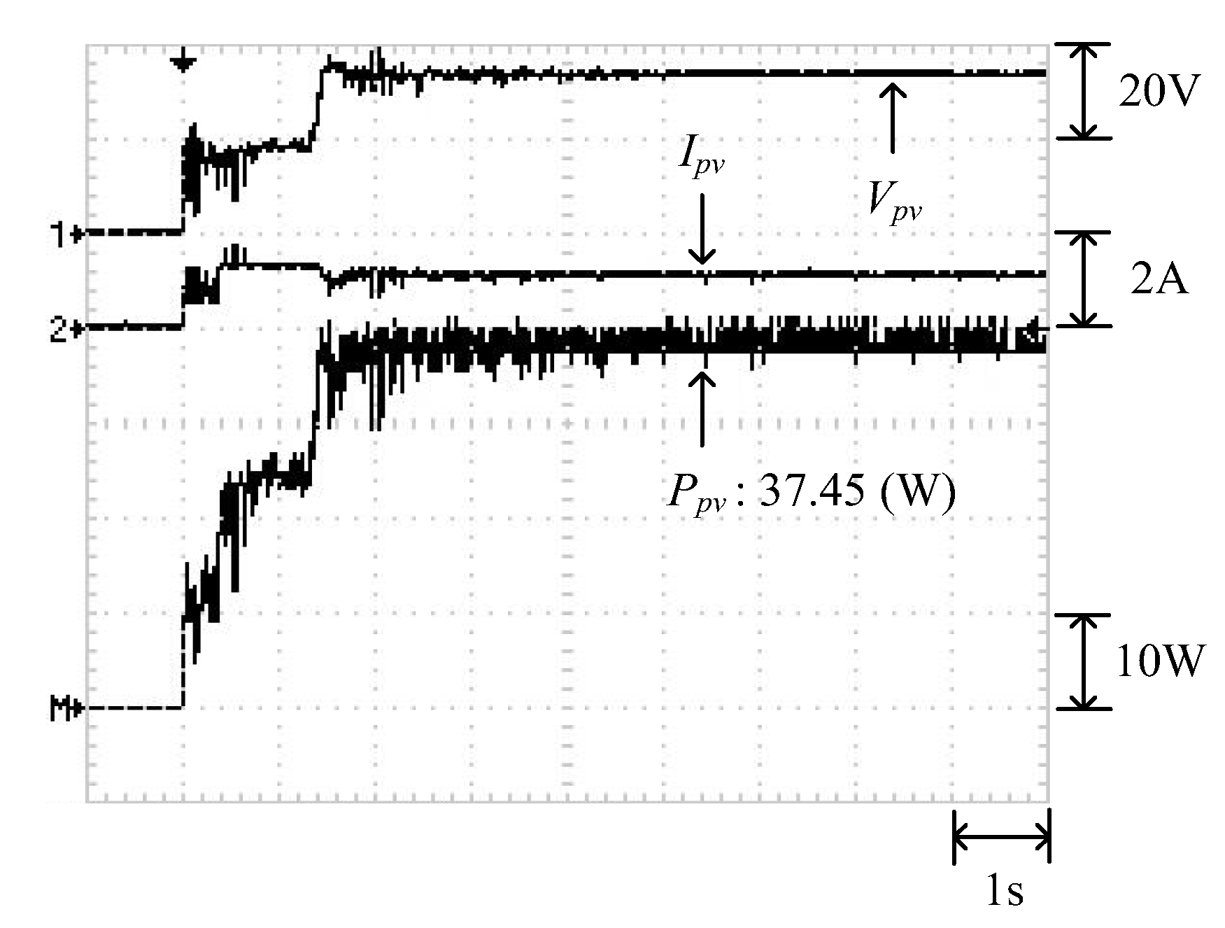
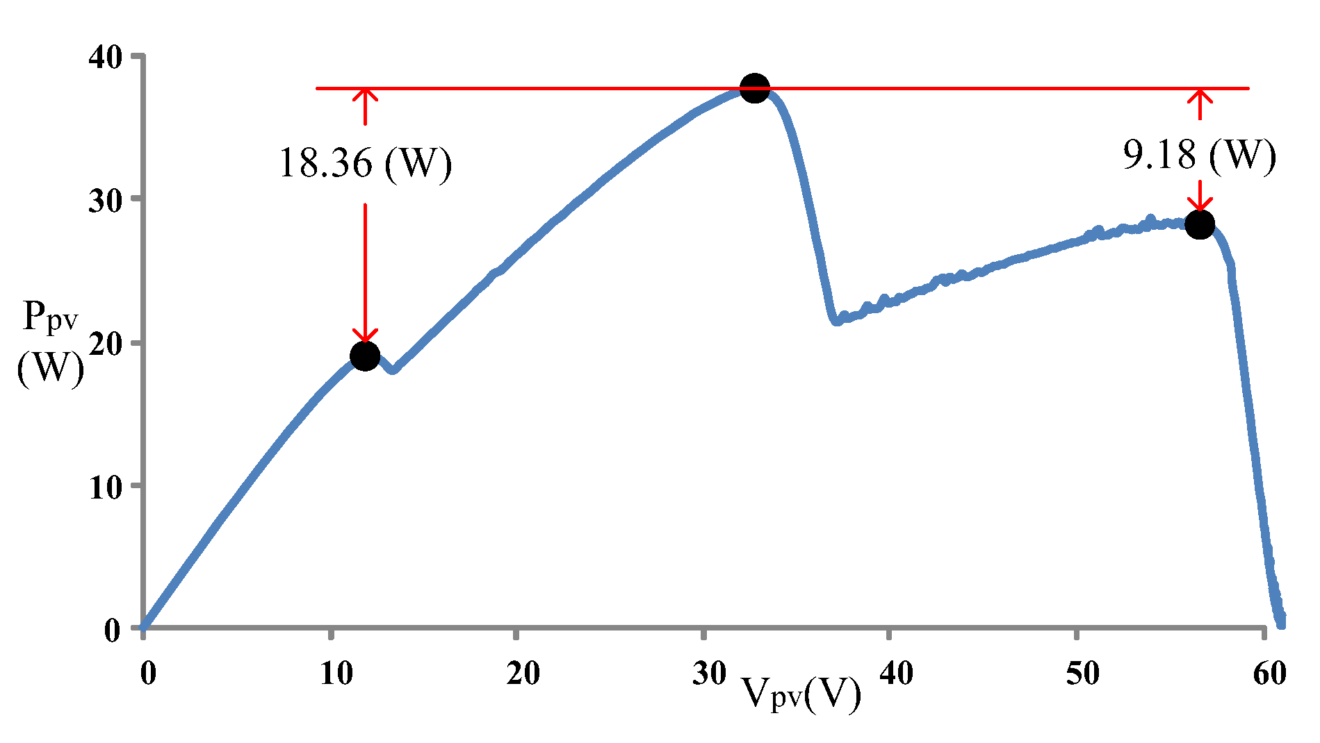
4. Testing Results of Conventional PSO and Modified PSO
5. Conclusions
Acknowledgments
Author Contributions
Conflicts of Interest
References
- Tofoli, F.L.; Pereira, D.C.; Paula, W.J. Comparative Study of Maximum Power Point Tracking Techniques for Photovoltaic Systems. Int. J. Photoenergy 2015, 2015, 812582. [Google Scholar] [CrossRef]
- Masoum, M.A.S.; Dehbonei, H.; Fuchs, E.F. Theoretical and Experimental Analyses of Photovoltaic Systems with Voltage and Current-based Maximum Power Point Tracking. IEEE Trans. Energy Convers. 2002, 17, 514–522. [Google Scholar] [CrossRef]
- Subudhi, B.; Pradhan, R.A. Comparative Study on Maximum Power Point Tracking Techniques for Photovoltaic Power Systems. IEEE Trans. Sustain. Energy 2013, 4, 89–98. [Google Scholar] [CrossRef]
- Elgendy, M.A.; Zahawi, B.; Atkinson, D.J. Assessment of Perturb and Observe MPPT Algorithm Implementation Techniques for PV Pumping Applications. IEEE Trans. Sustain. Energy 2012, 3, 21–33. [Google Scholar] [CrossRef]
- Visweswara, K. An Investigation of Incremental Conductance Based Maximum Power Point Tracking for Photovoltaic System. Energy Procedia 2014, 54, 11–20. [Google Scholar] [CrossRef]
- Soon, T.K.; Mekhilef, S. A Fast-converging MPPT Technique for Photovoltaic System under Fast-varying Solar Irradiation and Load Resistance. IEEE Trans. Ind. Inf. 2016, 11, 176–186. [Google Scholar] [CrossRef]
- Moballegh, S.; Jiang, J. Modeling, Prediction, and Experimental Validations of Power Peaks of PV Arrays under Partial Shading Conditions. IEEE Trans. Sustain. Energy 2014, 5, 293–300. [Google Scholar] [CrossRef]
- Khateb, A.E.; Rahim, N.A.; Selvaraj, J.; Uddin, M.N. Fuzzy-logic-controller-based SEPIC Converter for Maximum Power Point Tracking. IEEE Trans. Ind. Appl. 2014, 50, 2349–2358. [Google Scholar] [CrossRef]
- Algarín, C.R.; Giraldo, J.T.; Álvarez, O.R. Fuzzy Logic Based MPPT Controller for a PV System. Energies 2017, 10, 2036. [Google Scholar] [CrossRef]
- Kumar, P.; Jain, G.; Palwalia, D.K. Genetic Algorithm Based Maximum Power Tracking in Solar Power Generation. In Proceedings of the International Conference on Power and Advanced Control Engineering (ICPACE), Bangalore, India, 12–14 August 2015; pp. 1–6. [Google Scholar]
- Veerachary, M.; Senjyu, T.; Uezato, K. Neural Network Based Maximum Power Point Tracking of Coupled Inductor Interleaved Boost Converter Supplied PV System Using Fuzzy Controller. IEEE Trans. Ind. Electron. 2003, 50, 749–758. [Google Scholar] [CrossRef]
- Khanaki, R.; Radzi, M.A.M.; Marhaban, M.H. Artificial Neural Network Based Maximum Power Point Tracking Controller for Photovoltaic Standalone System. Int. J. Green Energy 2016, 13, 283–291. [Google Scholar] [CrossRef]
- Ma, S.L.; Chen, M.X.; Wu, J.W.; Huo, W.L.; Huang, L. Augmented Nonlinear Controller for Maximum Power-Point Tracking with Artificial Neural Network in Grid-Connected Photovoltaic Systems. Energies 2016, 9, 1005. [Google Scholar] [CrossRef]
- Besheer, A.H. Ant Colony System Based PI Maximum Power Point Tracking for Standalone Photovoltaic System. In Proceedings of the IEEE International Conference on Industrial Technology, Athens, Greece, 19–21 March 2012; pp. 693–698. [Google Scholar]
- Nivetha, V.; Gowri, G.V. Maximum Power Point Tracking of Photovoltaic System Using Ant Colony and Particle Swam Optimization Algorithms. In Proceedings of the 2nd International Conference on Electronics and Communication Systems (ICECS), Coimbatore, India, 26–27 February 2015; pp. 948–952. [Google Scholar]
- Ahmed, J.; Salam, Z. An Improved Method to Predict the Position of Maximum Power Point during Partial Shading for PV Arrays. IEEE Trans. Ind. Inf. 2015, 11, 1378–1387. [Google Scholar] [CrossRef]
- Hammami, M.; Grandi, G. A Single-Phase Multilevel PV Generation System with an Improved Ripple Correlation Control MPPT Algorithm. Energies 2017, 10, 2037. [Google Scholar] [CrossRef]
- Solar Pro Official Website. Available online: http://lapsys.co.jp/english (accessed on 10 May 2016).
- Kennedy, J.; Eberhart, R.C. Particle Swarm Optimization. In Proceedings of the IEEE International Conference on Neural Networks, Perth, Australia, 27 November–1 December 1995; pp. 1942–1948. [Google Scholar]
- Eberhart, R.C.; Kennedy, J. A New Optimizer Using Particle Swarm Theory. In Proceedings of the Sixth International Symposium on Micro Machine and Human Science, Nagoya, Japan, 4–6 October 1995; pp. 39–43. [Google Scholar]
- Chao, K.H.; Lin, Y.S.; Lai, U.D. Improved Particle Swarm Optimization for Maximum Power Point Tracking in Photovoltaic Module Arrays. Appl. Energy 2015, 158, 609–618. [Google Scholar] [CrossRef]
- Han, W.H. Comparison Study of Several Kinds of Inertia Weights for PSO. In Proceedings of the IEEE International Conference on Informatics and Computing, Shanghai, China, 10–12 December 2010; pp. 280–284. [Google Scholar]
- SANYO HIP 2017 Datasheet. Available online: http://iris.nyit.edu/~mbertome/solardecathlon/SDClerical/SD_DESIGN+DEVELOPMENT/091804_Sanyo190HITBrochure.pdf (accessed on 15 January 2016).
- PIC18Fxx20 Datasheet. Available online: http://pdf.datasheetcatalog.com/datasheet/microchip/39609b.pdf (accessed on 15 July 2014).
- Hart, D.W. Introduction to Power Electronics; Prentice Hall: New York, NY, USA, 2003. [Google Scholar]
- MP-170 Brochure. Available online: http://www.environmental-expert.com/products/model-mp-170-iv-checker-80092 (accessed on 15 July 2014).


| Conditions Items | ||
|---|---|---|
| 1 | ||
| 2 | ||
| 3 | ||
| 4 | ||
| 5 | ||
| 6 | ||
| 7 | ||
| 8 | ||
| 9 | ||
| 10 | ||
| 11 |
| Parameter | Configured Value |
|---|---|
| Particle number | 4 |
| Iteration number | 100 |
| Weighting (W) | 0.4 |
| Cognition learning factor (C1) | 2 |
| Social learning factor (C2) | 2 |
| Parameter | Configured Value |
|---|---|
| Particle number | 4 |
| Iteration number | 100 |
| Upper limit of weighting (Wmax) | 0.9 |
| Lower limit of weighting (Wmin) | 0.2 |
| Upper limit of cognition learning factor (C1,max) | 4 |
| Lower limit of cognition learning factor (C1,min) | 2 |
| Upper limit of social learning factor (C2,max) | 4 |
| Lower limit of social learning factor (C2,min) | 2 |
| Component Name | Specifications |
|---|---|
| Inductor L | 1 mH |
| Input capacity Cin | 470 μF/450 V |
| Output capacity Cout | 470 μF/450 V |
| Switching frequency f | 20 kHz |
| Power transistor | IRF460 (500 V/20 A) |
| Diode | DSEP30-12A (1200 V/30 A) |
| Parameter | Value |
|---|---|
| Rated maximum power () | 27.8 W |
| Current at maximum output power point () | 1.63 A |
| Voltage at maximum output power point () | 17.1 V |
| Short circuit current () | 1.82 A |
| Open circuit voltage () | 21.6 V |
| Case | Shading Conditions | Number of Peaks in the P–V Curve |
|---|---|---|
| 1 | 2-series 1-parallel: 0% shading + 40% shading | Double peaks |
| 2 | 3-series 1-parallel: 0% shading + 30% shading + 70% shading | Triple peaks |
| 3 | 4-series 1-parallel: 0% shading + 30% shading + 50% shading + 70% shading | Quadruple peaks |
| 4 | 2-series 2-parallel: (25% shading + 0% shading) // (55% shading + 0% shading) | Double peaks |
| Case | Number of Peaks in the P–V Curve | Conventional PSO | Modified PSO | ||
|---|---|---|---|---|---|
| Average Tracking Time | Average Maximum Power | Average Tracking Time | Average Maximum Power | ||
| 1 | Double peaks | 0.96 s | 35.21 W | 0.55 s | 35.32 W |
| 2 | Triple peaks | 1.89 s | 37.08 W | 0.98 s | 37.28 W |
| 3 | Quadruple peaks | Tracking failed | 35.73 W | 1.2 s | 45.55 W |
| 4 | Double peaks | 1.22 s | 64.68 W | 0.67 s | 64.73 W |
© 2018 by the authors. Licensee MDPI, Basel, Switzerland. This article is an open access article distributed under the terms and conditions of the Creative Commons Attribution (CC BY) license (http://creativecommons.org/licenses/by/4.0/).
Share and Cite
Chang, L.-Y.; Chung, Y.-N.; Chao, K.-H.; Kao, J.-J. Smart Global Maximum Power Point Tracking Controller of Photovoltaic Module Arrays. Energies 2018, 11, 567. https://doi.org/10.3390/en11030567
Chang L-Y, Chung Y-N, Chao K-H, Kao J-J. Smart Global Maximum Power Point Tracking Controller of Photovoltaic Module Arrays. Energies. 2018; 11(3):567. https://doi.org/10.3390/en11030567
Chicago/Turabian StyleChang, Long-Yi, Yi-Nung Chung, Kuei-Hsiang Chao, and Jia-Jing Kao. 2018. "Smart Global Maximum Power Point Tracking Controller of Photovoltaic Module Arrays" Energies 11, no. 3: 567. https://doi.org/10.3390/en11030567
APA StyleChang, L.-Y., Chung, Y.-N., Chao, K.-H., & Kao, J.-J. (2018). Smart Global Maximum Power Point Tracking Controller of Photovoltaic Module Arrays. Energies, 11(3), 567. https://doi.org/10.3390/en11030567


