Abstract
Measures to reduce nitrogen oxides (NOx) formation in industrial combustion processes often require up-scaling through pilot-scale facilities prior to being implemented in commercial scale, and scaling is therefore an important aspect of achieving lower NOx emissions. The current paper is a combined experimental and modelling study that aims to expand the understanding of constant velocity scaling for industrial jet flames applying high amounts of excess air. These types of flames are found in e.g., rotary kilns for production of iron ore pellets. The results show that, even if the combustion settings, velocity, and temperature profiles are correctly scaled, the concentration of oxygen experienced by the fuel during char combustion will scale differently. As the NO formation from the char combustion is important in these flames, the differences induced by the scaling has important impacts on the efficiencies of the applied primary measures. Increasing the rate of char combustion (to increase the Damköhler number), by using, for example, smaller-sized particles, in the pilot-scale is recommended to improve scaling.
1. Introduction
Nitrogen oxide (NOx) is a pollutant involved in the formation of several hazardous phenomena, most notably acid rain and photochemical smog. Legislation on emissions has motivated significant research into pollutant mitigation technologies, and this has resulted in reductions of NOx emissions during the last decades [1,2,3,4]. Regarding NOx emissions from stationary sources, the focus of legislative measures has been on power generation, which has driven the development of technological measures that are suited to these types of facilities, whereas industrial combustion processes have received less attention. However, this situation is changing, as emissions from industrial combustion plants now typically lie significantly above heat and power plants applying state-of-the-art technologies. Some of the industrial combustion processes differ significantly from conventional combustion systems and state-of-the-art technologies are not always applicable. There is, therefore, a need to adapt existing technologies to the conditions of industrial combustion or to develop new technologies for controlling the emissions from these processes. Since measures that affect the combustion process are usually tested in pilot-scale facilities prior to being applied in full-scale, it is critical that the effects of scaling are well understood.
Two commonly used principles for scaling combustion processes are: (1) constant velocity scaling; and (2) constant residence-time scaling. To relate these scaling criteria to the heat input, it is helpful to write the fuel input as:
where ρ0 and u0 are the inlet density and velocity of the combustion air, respectively [5]. D0 is the diameter of the combustion air inlet, and K is a proportionality constant that relates the air flow to the fuel input. Constant velocity scaling implies that u0 is kept constant, and constant residence-time scaling implies that D0/u0 is kept constant. The D0/u0 ratio, which will be referred to hereinafter as the mixing time, is representative of the flame residence time. Both scaling criteria aim at maintaining the fractional degree of mixing over the normalized length of the combustor [6]. If the reaction rates are faster than the mixing rate, combustion is controlled by mixing and should proceed in a similar manner independently of the scale and scaling method. For slower processes, constant residence-time scaling achieves a greater degree of similarity and is, in theory, the superior scaling method [6,7,8]. However, constant residence-time scaling is rarely applied owing to practical problems associated with severe pressure drops and low velocities, and constant velocity scaling is, thus, often preferred [7,9,10]. Weber and Breussin [8] have stated that for swirling pulverized fuel (PF) flames, both scaling methods achieve NOx emissions that are representative of the commercial scale when the thermal input of the pilot-scale is above 4 MW. At lower thermal inputs, NOx formation is underestimated, especially for constant velocity scaling. Weber and Breussin have attributed the decreased formation of NOx to a deeper penetration depth into the reverse flow zone in the vicinity of the burner. For thermal inputs <1 MW, they recommend constant residence-time scaling as well as a more finely milled fuel. The differences in particle trajectories between large scale and small scale flames, using constant velocity scaling, are demonstrated by CFD simulations in the recent work by Weber and Mancini [11], who also provide a good overview of scaling issues. The scaling studies in literature are mainly based on flames with a swirl-induced reverse flow zone (Type 1 and Type 2 flames, see [12,13] for more information about the flame classification system used by the International Flame Research Foundation (IFRF)). The novelty in this paper is the focus on jet flames (Type 0) and the application to rotary kilns for which little, if any, pilot-scale data that relates to scaling work, exists.
One industrial process that applies a PF-jet flame is the Grate–Kiln process for iron ore induration. In this process, combustion at high temperatures and with large volumes of excess air (4–6-times the stoichiometric requirement) powers the heat treatment of iron ore pellets in a rotary kiln. High temperatures and excess air are known to promote NOx formation, and the levels of NOx emissions from these units are indeed high. Several of the commonly used mitigation strategies are not easily applicable to the Grate–Kiln process due to practical limitations associated with the rotary kiln and the high content of iron dust in the off-gases. The Swedish iron ore company Luossavaara-Kiirunavaara Aktiebolag (LKAB) has worked with measures to reduce NOx emissions and are investigating how to overcome these limitations. Our recent work [14,15] on the LKAB pilot-scale kiln led to the conclusion that most of the NO in the Grate–Kiln process originates from the char-bound nitrogen in the fuel. The main premise for this conclusion was that the measured flame temperatures were not sufficiently high for significant thermal NO formation, and that the NO emissions decreased almost linearly with the amount of fuel-N introduced (30% of the coal, containing 1.4% nitrogen, was replaced with biomass that contained 0.1% nitrogen) [14]. LKAB has conducted several investigations of primary NOx mitigation and combustion efficiency in a similar pilot-scale setup [14,15,16,17,18,19,20,21,22]. However, the PF-jet flame suffers from scaling issues and the ways in which the pilot-scale results should be interpreted and transferred to the commercial scale are not clear, and low-NOx combustion remains to be implemented in industrial-scale iron ore kilns.
The current paper examines constant velocity scaling of PF-jet flames that apply a high degree of excess air and its implications on NOx formation. The overall aim is to derive a methodology for implementation of efficient primary NOx mitigation measures in such processes. As a case study, this paper assesses the LKAB pilot-plant kiln and compares it to a LKAB full-scale rotary kiln using detailed reaction modeling.
2. Materials and Methods
This section contains brief descriptions of the full-scale iron ore rotary kiln and the pilot-scale kiln that this work is based on, as well as descriptions of the used fuels and the detailed reaction model. For more detailed descriptions regarding kiln design and dimensions, the reader is directed to previous studies [14,15,23]. The scaling ratio, Ri, describes the ratio of parameter i in the full-scale to that in the pilot-scale. Table 1 defines the four scaling ratios used in this paper. All definitions are based on Equation (1).

Table 1.
Definitions of the scaling ratios (R-values) used in this paper.
In conventional furnaces, the combustion air is introduced through a burner into a confined combustion chamber, and D0 is the diameter of the burner throat. In iron ore rotary kilns, 20–50% of the stoichiometric air requirement for the combustion (about 5–10% of the total air) is introduced through the burner as primary air, while the remainder is introduced as secondary air through the two large openings located above and below the burner, respectively. A large proportion of the secondary air is entrained in the flame. In the present work, we have designated the kiln diameter as D0 because most of the air is introduced as secondary air.
2.1. Kilns
The data used for the full-scale kiln in this paper are from the LKAB KK2 Grate–Kiln plant in Kiruna, Sweden. The KK2 plant produces around 4 million tonnes of iron ore pellets annually and has been in operation since 1981. The kiln is inclined at an angle of 4° so the pellets gradually move forward under gravity. The kiln also has a rotation speed of 1.4 rpm so that the pellets are thoroughly mixed. The angle and the rotation of the kiln are not believed to influence the combustion significantly. The iron ore pellets form a rolling bed at the bottom of the kiln, taking up about 10% of the kiln volume. The fuel is usually a bituminous coal and the fuel heat rate is about 40 MW, depending on the pellet production rate. The secondary air is preheated to >1000 °C by the processed hot pellets. No secondary measures for NOx emissions reduction are implemented at the plant. More details about this plant can be found in the paper of Jonsson et al. [23].
The pilot-scale kiln was designed to resemble the full-scale kiln. It was scaled to RD = 7.7 and RQ = 69. For the same fuel and stoichiometry, this resulted in Ru = 1.19 and Rt = 6.6. Thus, constant velocity scaling was almost achieved. These numbers are calculated based on the assumption that the full-scale kiln is operating at 40 MW. If, for example, it is operating at 34 MW (due to a lower pellet production rate) the velocities are the same in the full-scale and pilot-scale (Ru = 1). An overview of the dimensions of the pilot-scale kiln and the full-scale kiln are presented in Table 2.
Table 2.
Dimensions of the full-scale kiln and the pilot-scale kiln.
Similar to the full-scale kiln, the pilot-scale kiln is inclined at an angle of 4°. The pellet bed is represented by cooling rods in the bottom of the kiln that simulate the heat sink created by the pellets in full-scale operation. The rotation is not included. The kiln is 4.4 m in length, and a pipe extends the total length to 14 m, so as to facilitate measurements of slagging. This extension is not considered part of the kiln. Measurement ports are available in both horizontal and vertical positions along the length of the kiln. Further details of the kiln and the burner can be found elsewhere [14].
2.2. Fuels
The fuel analyses for three coals tested in both the pilot-scale and full-scale are presented in Table 3, along with a heavy fuel oil (used during start-up and to address operational issues). The coal used in daily operation is referred to as the ‘reference coal’. The coal analyses, which are presented on an as-received basis, were performed prior to milling and drying. All the coals were milled to a diameter (d50) of around 35 µm, in both the full-scale and pilot-scale setups. The reference coal contained notably less nitrogen than the other coals.
Table 3.
Analysis of the fuels. The reference coal (Ref coal) is used in the full-scale plants today.
2.3. Modeling
In combustion processes, both the chemistry and the flow fields are important. However, modeling both these aspects in detail is challenging and computationally demanding. The modeling approach of the present work, which has also been used in our previous work [15], focused on the combustion chemistry and applied a simplified description of the transport processes.
2.3.1. Model Description
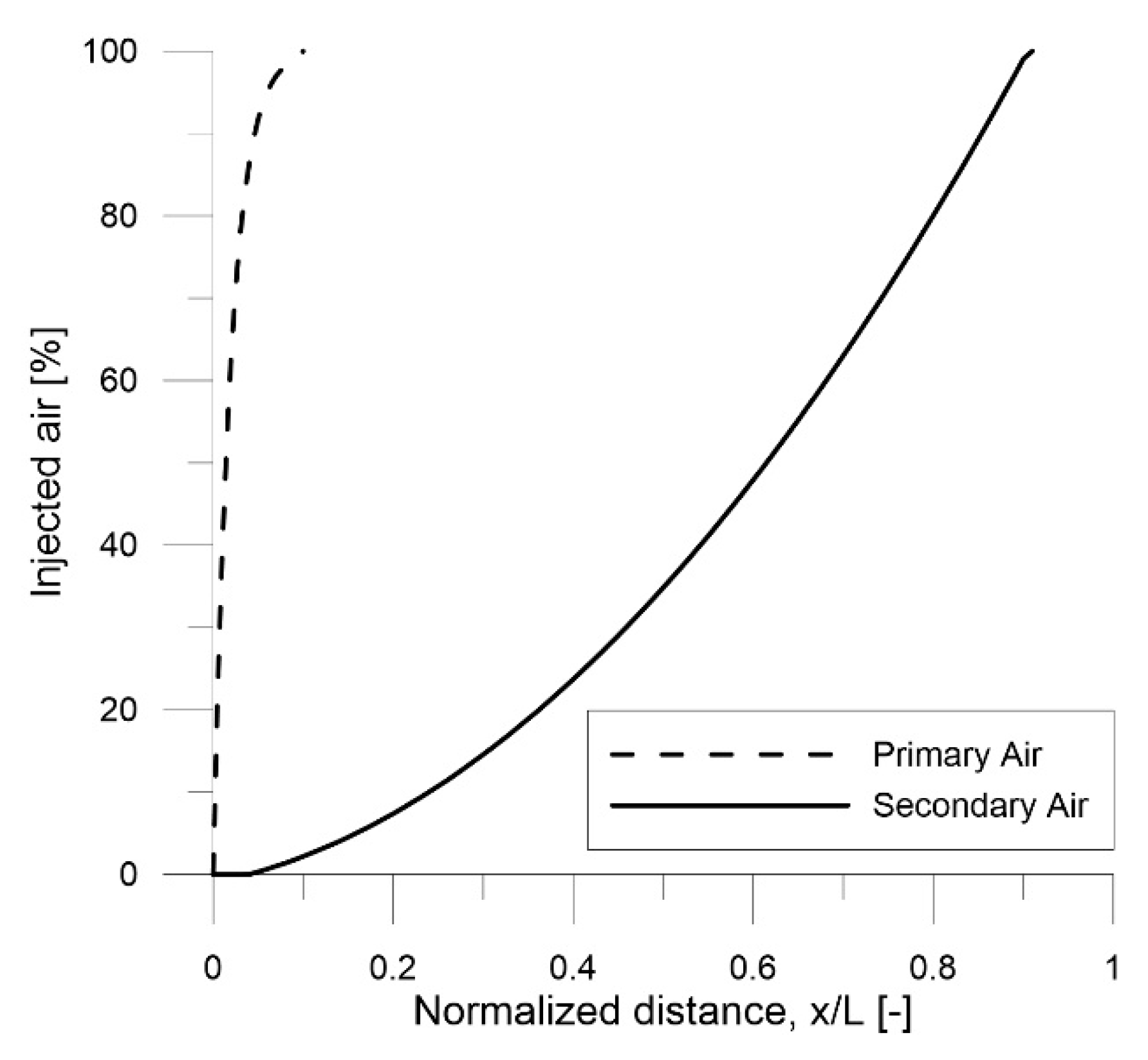
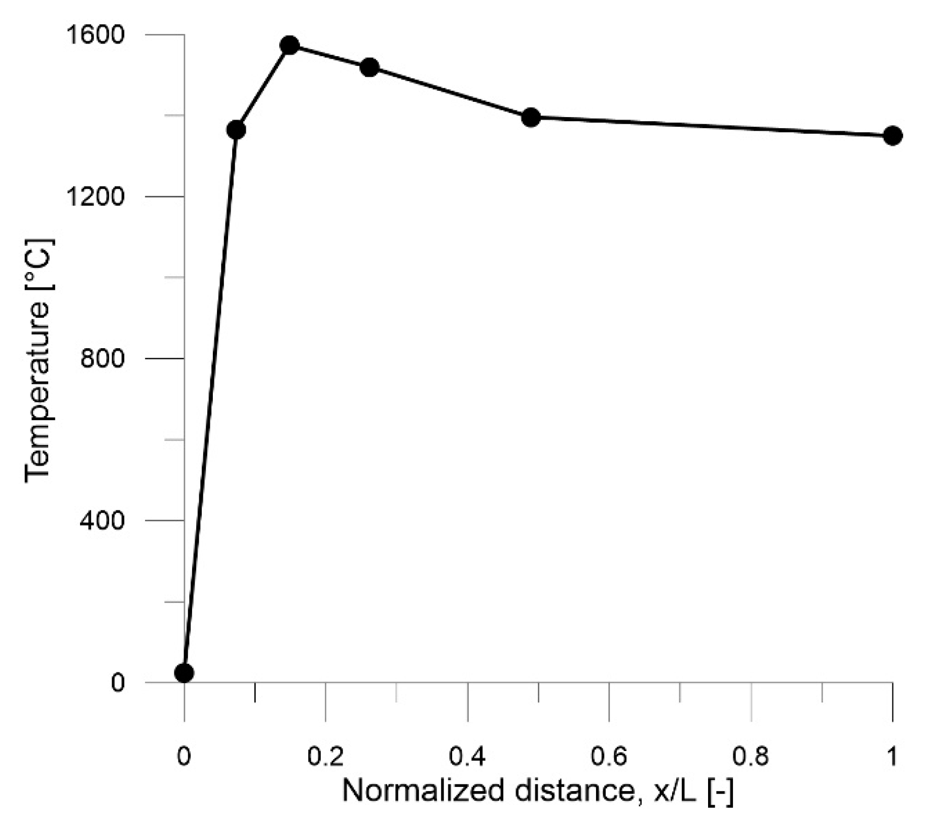
We used a plug flow reactor (PFR) model, with the fuel entering through the main inlet and with the primary and secondary air streams being injected gradually to the reacting flow. The air injection profiles, as well as the temperature profile were based on available in-flame measurement data from combusting the reference coal in the pilot-scale kiln [14]. The same profiles were applied to the full-scale kiln. Figure 1 presents the injection profiles for the primary and secondary air streams, and Figure 2 presents the temperature profile. Table 4 presents the combustion settings for both scales.

Figure 1.
Injection profiles of the primary and secondary air streams. The kiln lengths are 4.4 and 34.0 m for the pilot-scale and full-scale units, respectively.

Figure 2.
Temperature profile applied to the full-scale and pilot-scale models. The kiln lengths are 4.4 and 34.0 m for the pilot-scale and full-scale units, respectively.
Table 4.
Combustion settings in the model.
The detailed reaction mechanism proposed by Mendiara and Glarborg [24], which involves C1 and C2 chemistry as well as nitrogen chemistry, is applied to describe the gas-phase chemistry. The apparent kinetics derived from Jensen [25] for bituminous char combustion and NO reduction by bituminous char was applied to describe the heterogeneous interactions. The volatile species were assumed to comprise CO, CH4, H2 and HCN, and the char was assumed to consist of carbon and char-bound nitrogen. As there are currently no data regarding the partitioning of nitrogen between the volatiles and char, a 50/50 split was assumed. More details on how the fuel characteristics were implemented in the model can be found in our previous paper [15].
Throughout this paper, the degree of fuel conversion (X) at each point in the kiln will be used when comparing the pilot-scale unit to the full-scale unit. The degree of fuel conversion is defined as the weighted average of carbon and hydrogen conversion on a molar basis according to the following equation:
where XC,i and XH,i are the achieved conversion values of carbon and hydrogen to CO2 and H2O, respectively, at arbitrary step i in the reactor, and nC,tot and nH,tot are the total numbers of carbon and hydrogen atoms, respectively, in the system. The conversion values of carbon and hydrogen are calculated as follows:
where nCO2,i and nH2O,i are the local amounts of CO2 and H2O, respectively, at step (i). Using these definitions, the fuel conversion is only dependent on the final conversion to CO2 and H2O. An alternative way would have been to define fuel conversion as the conversion of the initial fuel. If this definition is used, the formation of e.g., CO from CH4 would be considered as fuel conversion. The reason for not choosing this definition was that CO was already present in the volatiles from the start and that there was no way to differentiate between the volatile CO and the formed CO.
The gaseous nitrogen mechanism consists of 79 species and 779 reactions. However, the three following reactions are central to NO formation and should be highlighted:
Reactions (1–3) comprise the well-known thermal NO mechanism, with forward Reaction (1) being the rate-limiting step. The reverse Reaction (1) and the forward Reaction (3) are also recognized as being crucial steps in the conversion of the light nitrogen species released during devolatilization (in this work, HCN). The heterogeneous mechanism related to NO formation consists of two global and apparent reactions, i.e., the oxidation of char-N and the reduction of NO by char:
where char(N) is the char-bound nitrogen and char(C) is the carbonaceous part of the char. The oxidation of char(C) proceeds in a manner similar to that shown for Reaction (4) but with CO as the product:
The reaction rate (in mole/cm3/s) of each reaction at each step of the PFR is given as an output from the model. The rates were integrated over the volume of each step and summed to obtain the net reaction rate in the PFR (obtained as mole/s). The net reaction rate was normalized to the fuel input (obtaining mole/s/MW) to account for the difference in scale between the pilot and full-scale units.
Homogeneous combustion reactions are limited either by the reaction kinetics or by mixing of the reactants, while char combustion may be limited further by the transport of oxygen to and into the char. However, since apparent kinetics were applied, it was not possible to determine whether the char combustion is controlled by the transport of oxygen or by the actual kinetics of char combustion. Nonetheless, the combustion process was defined as: (1) mixing-controlled if the O2 is consumed as fast as or faster than the rate at which it is injected; or (2) as kinetically controlled if the O2 is consumed slower than the rate at which it is injected. Dividing the consumption rate of O2 by the mixing rate of O2 gives the Damköhler number:
this Damköhler number is based exclusively on O2 and represents the relationship between the combustion rate and mixing rate. Using the definition above we get:
- Da ≥ 1: mixing-controlled combustion process
- Da < 1: kinetically controlled combustion process
2.3.2. Sensitivity Analysis
The sensitivity analysis includes a discussion of the fuel particle size and the relationship between the pilot-scale and full-scale. The reason for investigating the fuel particle size is because it is one of the few parameters that often remains constant during scaling due to practical limitations relating to milling and feeding. A constant particle size during constant-velocity scaling may cause discrepancies between the scales, as the time for char combustion does not decrease in proportion to the time for mixing, if the char combustion is not mixing-controlled. Smart and Morgan [6] state that it is important to preserve the coal particle size as it affects in-flame temperature and gas density distributions but they also highlight the problem of keeping the particle size constant during constant velocity scaling. Weber and Breussin [8] recommend reducing the particle size when performing prototype experiments below 1 MW to achieve better scaling. If the combustion is not entirely controlled by mixing, a better scaling process might be achieved with a smaller particle size, such that the specific surface area is decreased by the value of Rt. Since the surface area is dependent upon the diameter to the power of two, the diameter of the particles should be reduced by the square root of Rt (i.e., √Rt = 2.57 for the pilot-scale kiln). In the model, the particle size was represented by the pre-exponential factors in the Arrhenius expressions for the heterogeneous reactions, i.e., a smaller particle size gives an increased reaction rate corresponding to Rt. The devolatilization process and the temperature profile are maintained independent of the particle size.
The sensitivity to scale on NOx formation using constant-velocity scaling was also mapped. The full-scale (Q = 40 MW, D0 = 5 m) was used as the basis and scaled down to 10, 1, 0.5 and 0.1 MW. The scaling ratios for each case are presented in Table 5.
Table 5.
Scaling ratios for constant-velocity scaling of the full-scale kiln.
3. Results and Discussion
The measured NOx emissions (expressed as mgNO2/MJfuel) for the fuels used in the full-scale and pilot-scale kilns are shown in Figure 3. The reason for normalizing the emissions is to account for small differences in stoichiometry and fuel feed between the cases, since the conditions have varied slightly between the measurement occasions. The limit stated in the Medium Combustion Plant Directive (MCPD) [26] is included as reference (more information about this in Appendix A). The figure shows that the levels of NOx emissions are significantly higher in the pilot-scale than in full-scale. Oil has the lowest NOx emissions in the full-scale, but by far the highest emissions in the pilot-scale. Since the main mechanism for NOx formation during oil combustion is thermal NO, the temperatures must be higher when combusting oil in the pilot-scale as compared to the full-scale. Even though the emissions are high (relative to the MCPD) for the Reference coal, Coal 1, and Coal 2 in full-scale, only about 30%, 18%, and 20%, respectively, of the theoretical maximum NOx emissions originate from the fuel-bound nitrogen. In the pilot-scale, the corresponding values are 54%, 38%, and 38%.
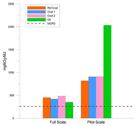
Figure 3.
Normalized NOx emissions from the full-scale and pilot-scale kilns burning three coals and one oil. The dashed line (MCPD) refers to the emission limits for coal combustion listed in the Medium Combustion Plant Directive.
The modeling results are presented in three parts. First, the modelled pilot-scale and full-scale flames are presented so as to discuss the differences related to scaling. Then the sensitivity analyses of particle size and scaling magnitude are presented. Finally, a discussion of the uncertainties related to the modeling concludes the chapter. The reference coal is used as fuel in all simulations.
3.1. Modeling of the Flames
3.1.1. Combustion
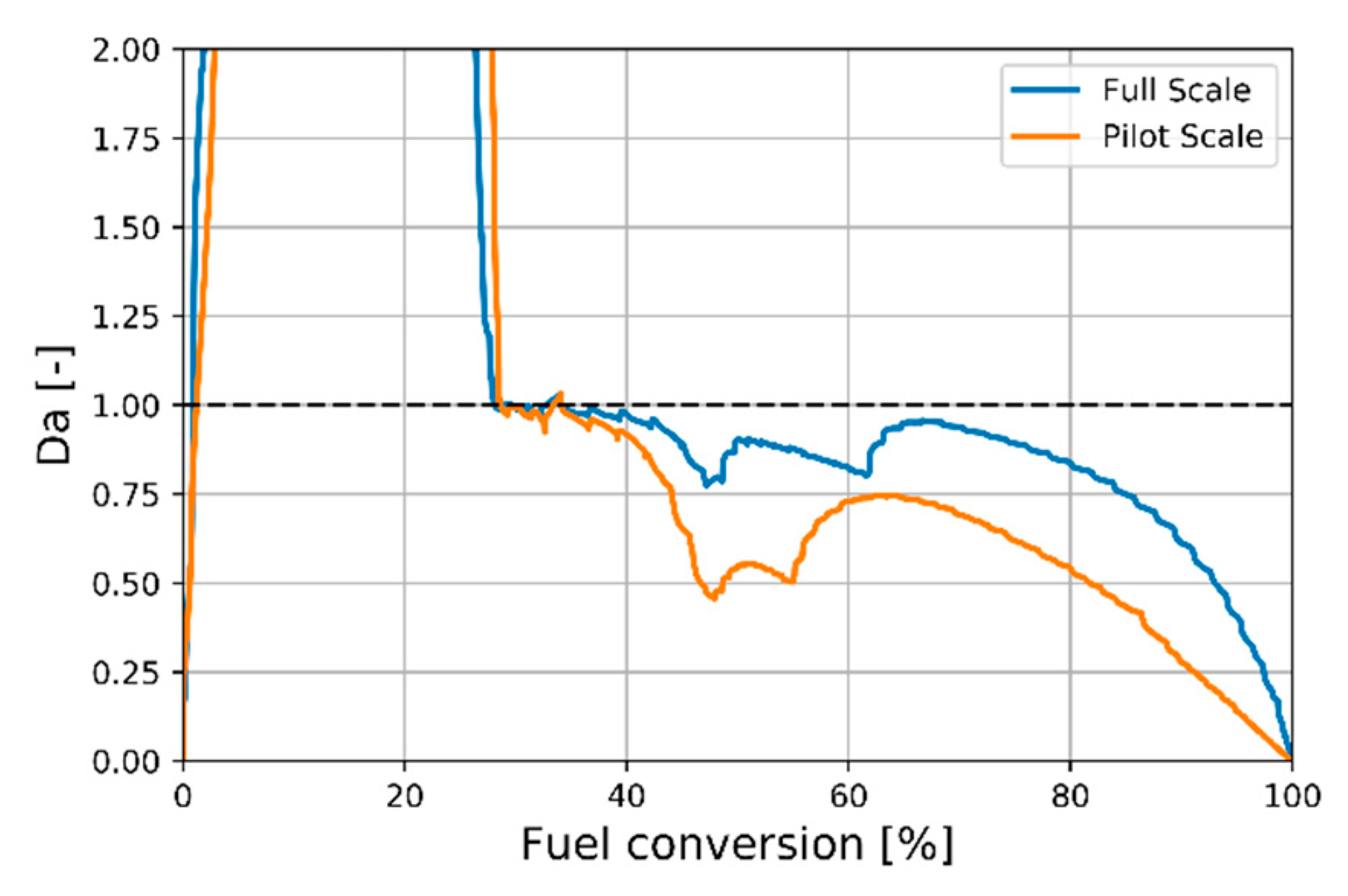
Figure 4 presents the modeled fuel conversion as a function of time in the two kiln flames. The time to reach complete fuel conversion is about five times longer in the full-scale than in the pilot-scale. However, the mixing time is 6.6 times longer in the full-scale kiln (see Section 2.1). Since the times for mixing and complete conversion are not changed by the same magnitude, the combustion is not entirely mixing-controlled. Figure 5 presents the Damköhler number as a function of the fuel conversion. The Damköhler number is greater than unity at a fuel conversion of <30%, which means that O2 is consumed at a rate faster than it is injected. A large fraction of the O2 consumed during this stage has mixed with the fuel prior to ignition. In the fuel conversion range of 30–40%, the Damköhler number is at unity, i.e., the oxygen is consumed as soon as it is mixed with the flame. After 40%, the Damköhler number is slightly less than unity and the combustion is, thus, in the kinetically controlled regime.
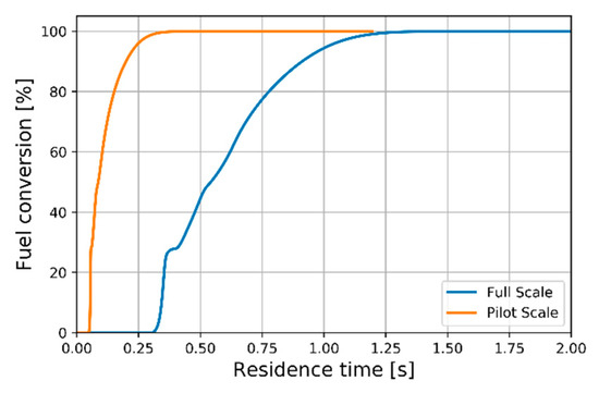
Figure 4.
Fuel conversion in relation to gas residence time in the pilot-scale and full-scale flames.

Figure 5.
The Damköhler number plotted against the fuel conversion in the pilot-scale and full-scale flames. The y-axis is capped at 2 to enhance clarity around unity, which is represented by the dashed line.
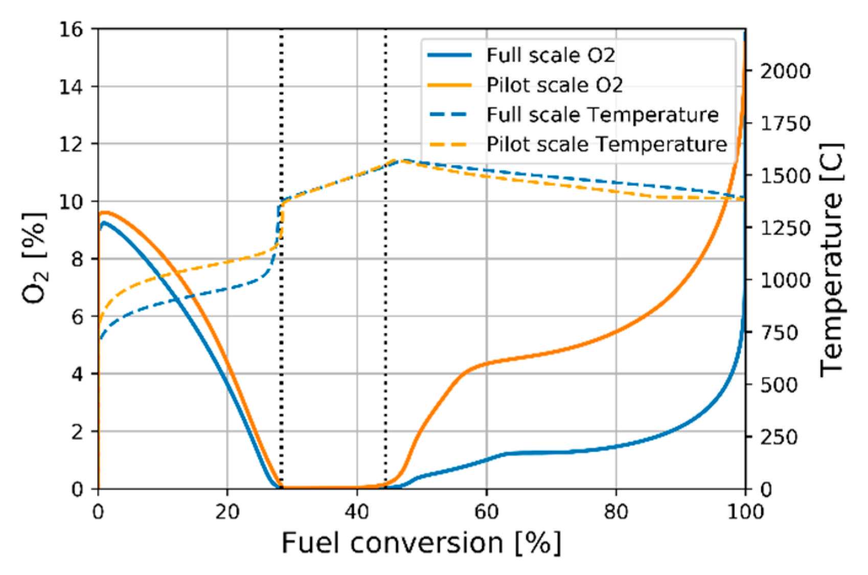
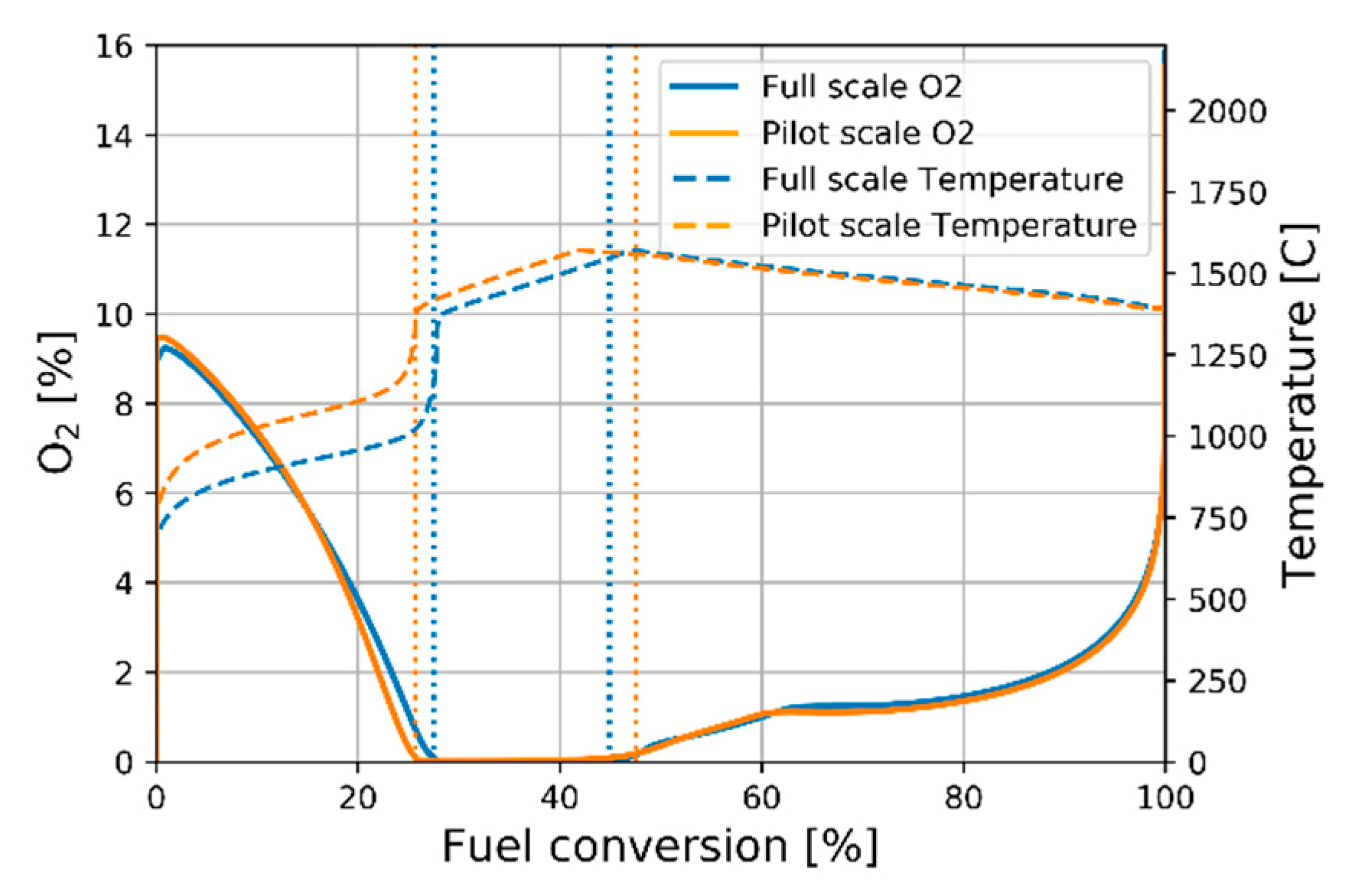
Figure 6 presents the oxygen concentration profile, as well as the temperature profile as a function of the fuel conversion in the two flames. In the figure, the combustion process is divided into three zones, separated by vertical lines. The first zone, which ends at the point where the oxygen concentration becomes zero, represents the devolatilization stage. Here, the temperature is <1200 °C and the main process is CH4 conversion to CO, H2 and H2O. The second zone, which ends when 95% of the hydrogen (Xh) is converted, is where volatile combustion dominates. The third zone is dominated by char combustion. The zones begin and end at the same fuel conversion level in the two kilns. The O2 profiles in the first half of the fuel conversion process are similar in both flames and can be attributed to the rapid kinetics of the homogeneous reactions that cause the process to operate in a mixing-controlled regime (Da ≥ 1). In contrast, the heterogeneous reactions are slow and make the char conversion process operate in a kinetically controlled regime (Da < 1), which causes the O2 levels to rise. The most distinctive difference between the pilot-scale and full-scale flames is the higher oxygen concentration seen during char combustion in the pilot-scale. This is a consequence of the lower Damköhler number for the char combustion in pilot-scale (Figure 5).

Figure 6.
Oxygen and temperature profiles as functions of the fuel conversion in the pilot-scale and full-scale flames. The vertical lines indicate the beginning and end of the volatile combustion zone.
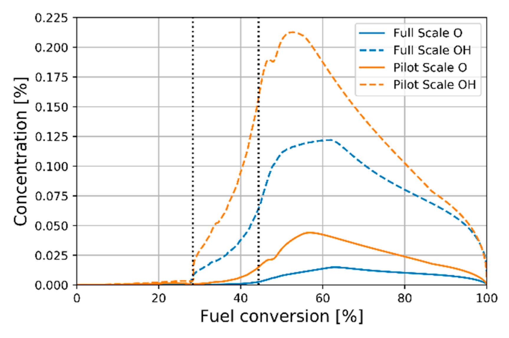
Even though the oxygen concentrations in both kilns are close to zero during volatile combustion, the homogeneous conditions still differ. This is evident in Figure 7, where the in-flame concentration profiles of the OH and O radicals are shown. These concentrations of radicals are higher in the pilot-scale, which means that the atmosphere is more oxidizing during the volatile combustion as well.
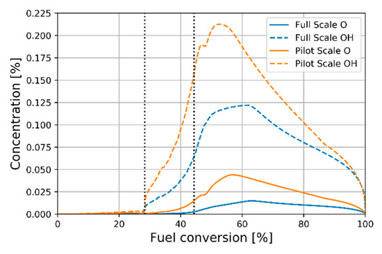
Figure 7.
The O and OH profiles in the in the pilot-scale and full-scale flames as functions of the fuel conversion. The vertical lines indicate the beginning and end of the volatile combustion zone.
3.1.2. Nitrogen Chemistry
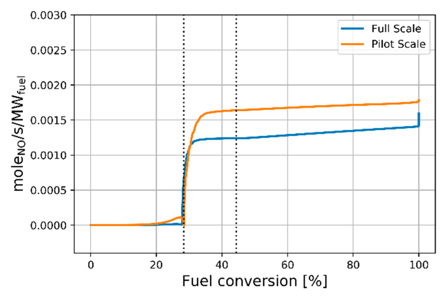
The sum of NO formed by Reactions 1–3 is presented in Figure 8. NO formation starts at around the same level of fuel conversion in both flame scales, although it reaches a higher level in the pilot-scale. Since the temperature is similar at both scales in the second zone (see Figure 6), the discrepancy must be due to a greater availability of reactants in the pilot-scale. As shown in Figure 7, the OH levels are significantly higher in the pilot-scale, and they will promote NO formation via Reaction 3. The steep increase in NO formation is NO formed from vol-N, while the subsequent slower continuous increase in NO formation reflects NO formed from N2, i.e., thermal formation. The thermal mechanism is slightly more prominent in the full-scale kiln (even proceeding after complete conversion of the fuel), which is likely a result of the longer residence time.
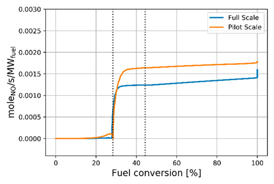
Figure 8.
Sum of the contributions from Reactions 1–3 in the pilot-scale and full-scale kilns.
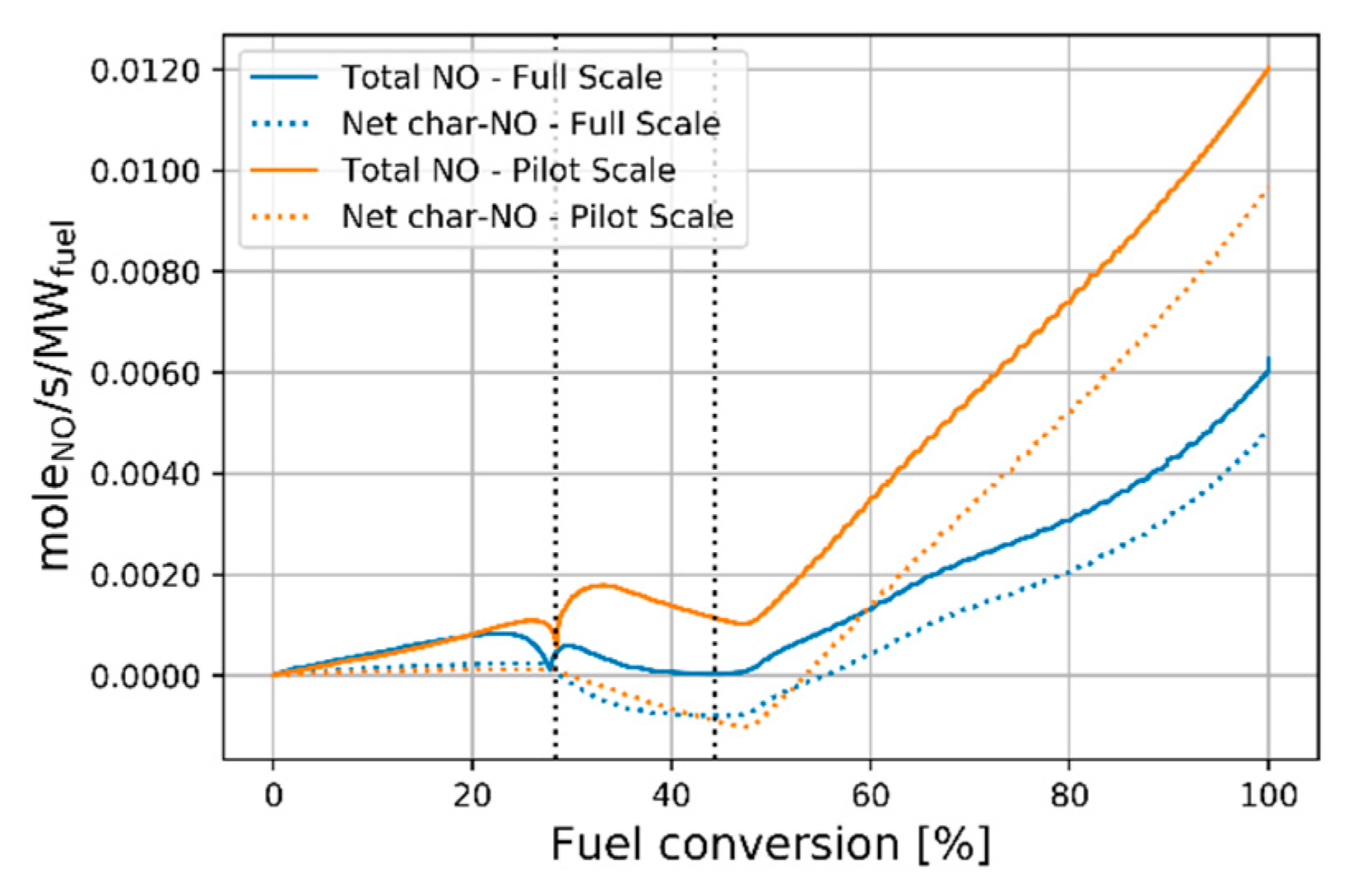
The total level of NO formation, as well as the net level of NO formation from the heterogeneous reaction (i.e., the sum of Reactions 4 and 5) are shown in Figure 9. Comparing the y-axes in Figure 8 and Figure 9, it is clear that heterogeneous NO formation dominates over homogeneous NO formation. The net level of heterogeneous NO formation is negative during volatile combustion, which indicates that NO reduction on char is faster than NO formation from char-N. During char combustion, the gradient of NO formation is significantly steeper for the pilot-scale flame, which is a direct effect of the higher oxygen concentration during this process (see Figure 6).
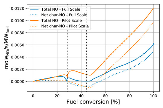
Figure 9.
Total levels of NO formation and the contributions from the heterogeneous reactions in the pilot-scale and full-scale kilns.
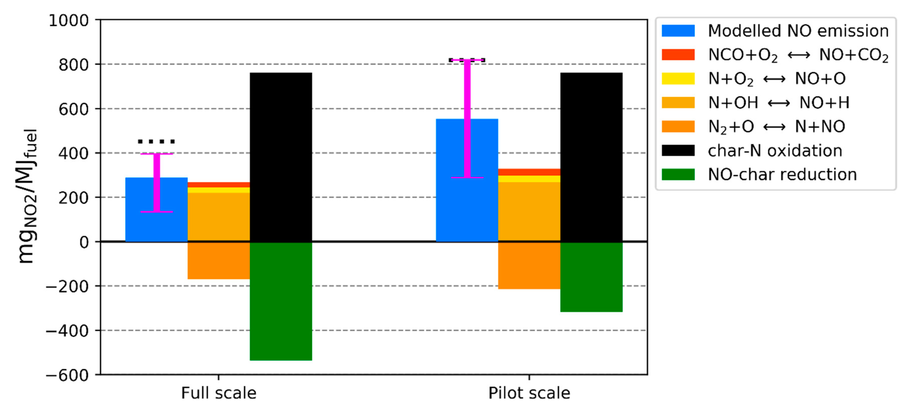
Figure 10 presents an overview of the NO formation paths according to the model and compares the modeled NO emissions with the measurements made in the pilot-scale and full-scale kilns. The blue bar represents the modeled NO emissions and the dotted horizontal line above the blue bar represents the measured emissions. The model under-predicts by about 35% the NO emissions from the two flames. A likely reason for this discrepancy is the arbitrary partitioning of nitrogen between volatiles and char in the model, which is set at 1:1 (vol-N:char-N). For this reason, simulations with partitioning ratios of 1:3 and 3:1 are shown as error bars in the figure. A better match between the modeled values and measurements is achieved if nitrogen partitioning is set so that 25% of the fuel-N is released with the volatiles (i.e., 1:3). This is a plausible partitioning ratio since on a dry ash-free basis the reference coal consists of 76% char and 24% volatiles. However, the nitrogen partitioning is dependent upon the temperature during the pyrolysis and is not easily determined without experimentation.
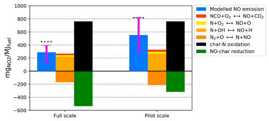
Figure 10.
Levels of NO formation—total and distributed between the most important reactions—with a 1:1 fuel-N partitioning between volatiles and char. The error bars indicate the sensitivity to fuel-N partitioning for a 3:1 split (lower error bar) and a 1:3 split (upper error bar). The dots above the blue bars represent the measured emissions from the pilot-scale and full-scale kilns.
The central bar in Figure 10 represents the dominating homogeneous NO reactions, and the right-hand-side bar indicates the two global heterogeneous nitrogen reactions. The homogeneous chemistry is dominated by Reactions 1 and 3 (i.e., N + OH and N + NO), while Reaction 2 (N + O2) plays a minor role in the two flames. Of the remaining NO-forming reactions in the mechanism, oxidation of NCO by O2 was found to be significant and is, therefore, included in the figure. Since all the char-N is initially converted to NO in the model, the value for char-N oxidation is the same for both scales and the level of NO reduction by char determines the difference between the scales.
3.2. Sensitivity Analysis
3.2.1. Char Combustion Rate
Figure 11 displays the temperature and oxygen profiles when smaller particle sizes are used in the pilot-scale kiln, i.e., the heterogeneous reaction rates are increased by a factor of Rt (6.6). The full-scale is shown for comparison. The O2 level is now similar during char combustion in the two scales, although the temperature in the first two zones has increased, and the combustion zones (separated by the vertical dotted lines) no longer appear at the same fuel conversion value. These results highlight the difficulty associated with achieving identical combustion at different scales, since a measure that targets one part of the combustion process may alter the combustion in another part. It should be noted that the same temperature profile is still used in both simulations (relative to the normalized distance), and that the higher temperature in the pilot-scale is simply the result of faster fuel conversion, which alters the relationship between the fuel conversion profile and the temperature profile. Figure 12 presents the Damköhler numbers and confirms that the reaction rate and mixing rate in the two flames now lie significantly closer to each other than when the same particle size (i.e., reaction rates) was used.
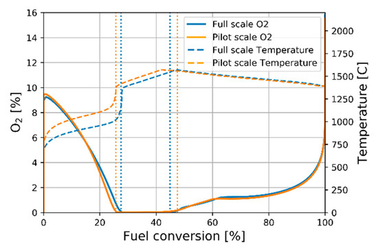
Figure 11.
Oxygen and temperature profiles when an increased heterogeneous rate is applied in the modeling of the pilot-scale flame.
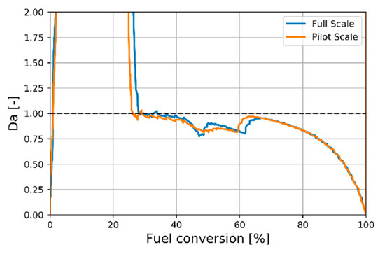
Figure 12.
Comparison of the Damköhler numbers when smaller particles are used in the pilot-scale flame.
Figure 13 summarizes the contributions from the most important reactions. The net level of NO formation is now similar in the two scales, mainly because the level of NO reduction by char is increased relative to the base case (Figure 10). The modeling results indicate that increasing the char reaction rate (decreasing the particle size) in the pilot-scale is a good measure to improve the representability of the full-scale. The contributions from the dominant reactions are, however, not identical. The rates of NO formation from the homogeneous reactions and NO reduction by char become slightly higher in the pilot-scale flame. This is due to the NO reduction rate on char occurring on a similar timescale as vol-N conversion, which pushes the homogeneous reactions towards more NO formation, since the OH/NO ratio increases.
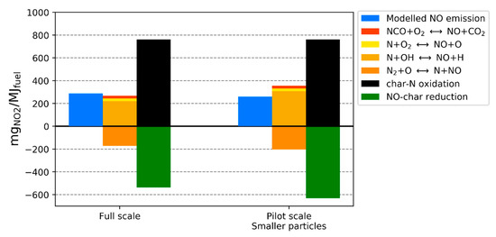
Figure 13.
Levels of NO formation from the most important reactions in the full-scale and pilot-scale flames, with smaller particles in the pilot-scale (simulated by increasing the heterogeneous reaction rates).
Increasing the specific surface area of spherical particles 6.6-fold is the equivalent of reducing the particle diameter 2.57-fold, which in practice would mean a diameter in the range of 10–15 µm. That a more finely milled fuel would be recommended is in agreement with the conclusion reached by Weber and Breussin [8], who also proposed that constant residence time scaling would give better results in the case of an input <1 MW. It should, however, be noted that a reduction in particle size can influence other aspects of the combustion process, e.g., the temperature profile, which could impair the similarity between the kilns.
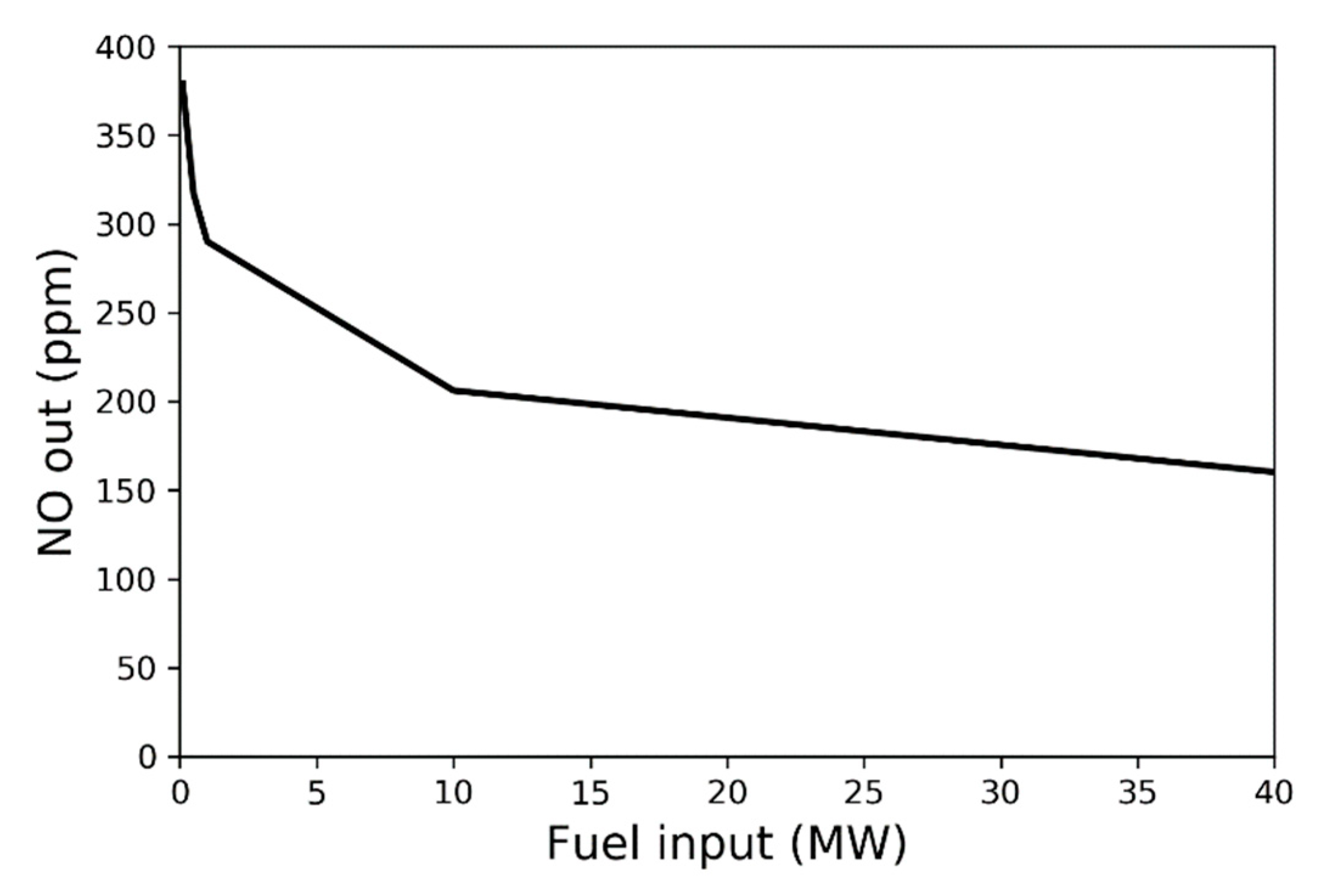
3.2.2. Scale
Figure 14 presents the outlet NO fraction from the sensitivity analysis of scaling using constant-velocity scaling. The figure shows that the level of NO increases exponentially as the fuel input is decreased. This is contrary to the conclusion drawn by Weber and Breussin [8] from their experimental and modeling work on Type 1 and Type 2 flames. They found that NOx emissions decreased exponentially when the thermal input was decreased, and they attributed this trend to changes in the depth of penetration into the reverse flow zone. For externally staged flames, Weber [5] observed, however, an increase in the levels of NOx with decreasing thermal input. Although it is unclear how one can relate these previous studies to the current work, it is likely that PF-jet flames that apply large amounts of excess air scale differently from other combustion systems, given that most of the NO originates from char-N.
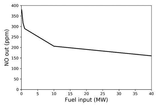
Figure 14.
NOx emissions as a function of fuel input with constant velocity scaling.
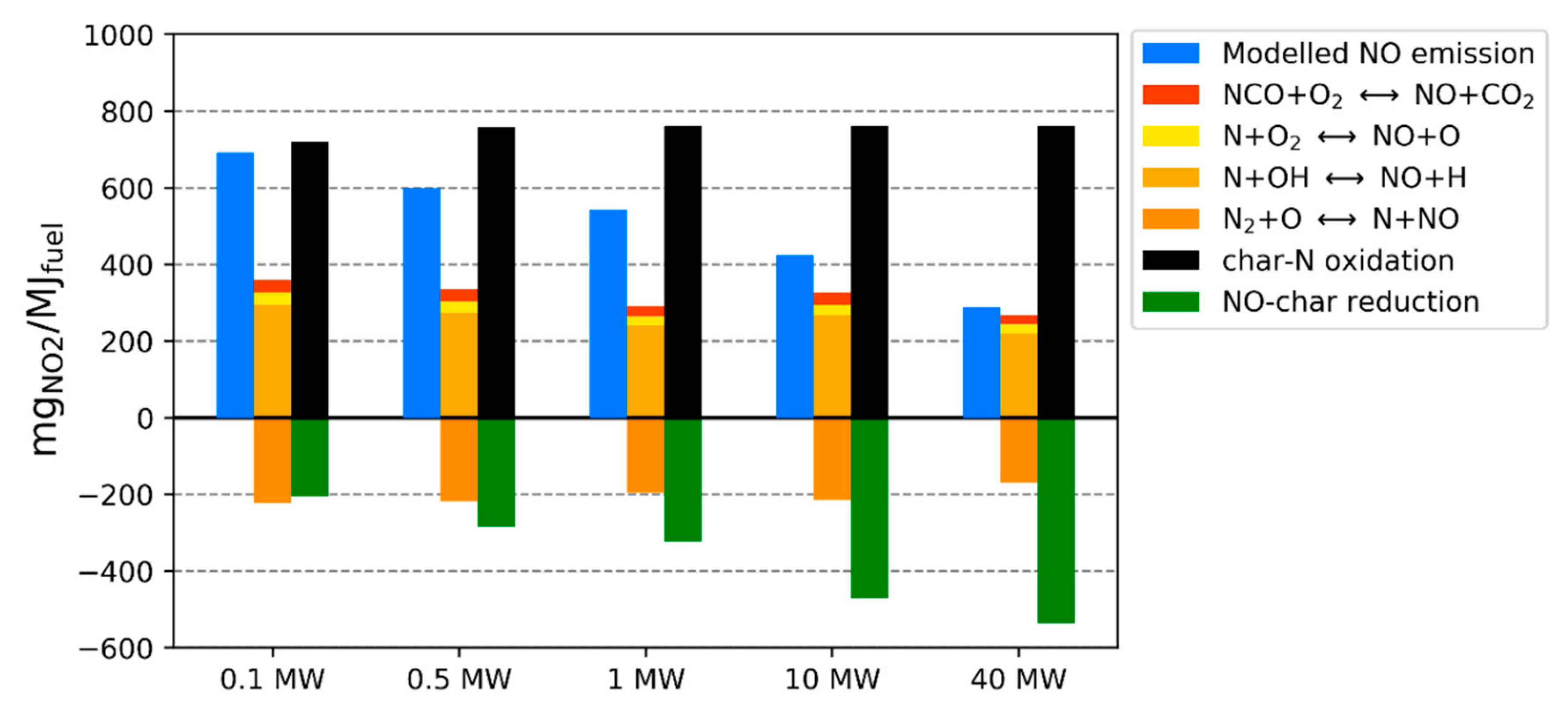
Figure 15 presents the contributions of the main NO-forming reactions. In similarity to the simulations in Section 3.1, a decreased NO reduction by char is responsible for the higher NO emissions at smaller scale. The oxidation of char-N is slightly lower at 0.1 MW than in the other cases, which is due to the very short residence time yielding incomplete combustion. The homogeneous chemistry varies slightly in a non-linear fashion, although these variations are small when compared to the heterogeneous reactions. These variations may however become significant in more conventional flames since the contribution from char-N is usually smaller in such systems.
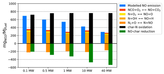
Figure 15.
Levels of NO formation for the different kiln scales using a constant velocity scaling.
3.3. Uncertainties Related to the Modeling
This section will discuss two uncertainties related to aspects of the applied model: the temperature profile and the heterogeneous reactions.
The temperature profile is based on measurements made in the pilot-scale kiln and has been kept constant in all the simulations. However, the heat input per volume is significantly higher in the pilot-scale kiln (0.40 MW/m3) than in the full-scale kiln (0.06 MW/m3). Therefore, it is likely that the flame temperature profile reaches higher levels in the pilot-scale than in the full-scale. This is supported by the significantly higher measured level of NOx emissions when combusting oil (Figure 3). Unfortunately, there are no reliable measurements of temperature or gas composition for oil combustion in the pilot-scale kiln. In our previous modeling paper [15], the effect of temperature on NO formation for the reference coal was investigated, and it was concluded that the temperature levels needed to be 300 °C higher in the pilot-scale for a significant change in NO formation to occur. So, although temperature is a central parameter in combustion, it seems reasonable to assume the same temperature profile for the full-scale kiln as for the pilot-scale kiln.
Heterogeneous chemistry during combustion is more complex to describe accurately than homogeneous chemistry, owing to mass transport phenomena. The apparent heterogeneous kinetics used in the model is a simplification of the char conversion process, since no distinction is drawn between kinetics and mass transfer, and only heterogeneous reactions with O2 and NO are included. A sensitivity analysis of the pre-exponential A-factor and the activation energy was performed in our previous work [15], and it showed that the apparent kinetics play an important role and can affect significantly the NO emissions if, for instance, the pre-exponential A-factor is changed by about 90%. However, the implication of this uncertainty for the current conclusions is only significant if it keeps the Damköhler number above unity for the entire combustion process. As long as the Damköhler number falls below unity and the combustion enters the kinetically controlled regime, the O2 levels will increase faster in the pilot-scale due to the faster mixing, and NO formation will be higher as a result. For the purpose of this paper, the apparent kinetics are deemed to be sufficient to explain the NO trends observed during scaling.
4. Conclusions
The constant velocity scaling criteria has been investigated for scaling of pulverized fuel jet flames that apply a high degree of excess air, with a focus on NOx formation. This was performed by comparing the NO formation in a full-scale rotary kiln for iron ore production (around 40 MW) with its pilot-scale kiln (580 kW) supported by detailed reaction modelling. The measured NOx emissions from the pilot-scale were almost twice as high as the full-scale kiln when coal was combusted, and the NOx formation mechanisms are thus not well-scaled.
The modeling captures the main trends in NOx emissions for the pilot-scale and full-scale flames, i.e., significantly more NOx is produced in the smaller scale. For coals, the modeling points to poor scaling of the heterogeneous combustion, while the homogeneous reactions scale significantly better. The reason for this discrepancy is that the Damköhler number is significantly lower in the pilot-scale during char combustion, whereas it is preserved during the mixing-controlled volatile combustion. As a result, the char combustion proceeds in a more oxygen-rich environment. Scaling the particle size accordingly could, in theory, provide better scaling of the heterogeneous reactions.
Author Contributions
Conceptualization, R.E., F.N. and C.F.; Data curation, R.E.; Formal analysis, R.E.; Funding acquisition, F.N., C.F. and K.A.; Investigation, R.E.; Methodology, R.E., F.N., T.A. and K.A.; Project administration, F.N. and K.A.; Resources, C.F.; Supervision, F.N., T.A. and K.A.; Visualization, R.E.; Writing—original draft, R.E.; Writing—review & editing, F.N., T.A., C.F. and K.A.
Funding
This research was funded by the Swedish Energy Agency, grant number P37204-1. The APC was also funded by P37204-1.
Conflicts of Interest
The authors declare no conflict of interest.
Nomenclature
| Symbols | |
| Q | Fuel input |
| ρ0 | density of combustion air |
| u0 | velocity of combustion air |
| D0 | Diameter of burner throat or kiln |
| K | proportionality constant |
| RQ | Ratio between fuel input in full-scale and pilot-scale |
| RD | Ratio between diameter in full-scale and pilot-scale |
| Ru | Ratio between combustion air velocity in full-scale and pilot-scale |
| Rt | Ratio between mixing time in full-scale and pilot-scale |
| Xi | Fuel conversion at a given point i |
| XC,i | Conversion of fuel-carbon at a given point i |
| XH,i | Conversion of fuel-hydrogen at a given point i |
| nj,i | Molar flow of component j at a given point i |
| Da | Damköhler number |
Appendix A
This is a short discussion about the dashed line in Figure 3.
The emissions regulations related to heat and power generation throughout the European Union (EU) set emission limits for coal combustion in the Medium Combustion Plant Directive (MCPD) [26], which is used as a reference in Figure 3. This limit is given in mgNO2/m3n corrected for 6% O2 in the flue gases. Normalization to an oxygen concentration is, however, not applicable to the iron ore pelletization process, in which significant amounts of oxygen react with the magnetite to form hematite. Therefore, these emissions are reported in mgNO2/MJfuel. The conversion from mgNO2/m3n at 6% O2 to mgNO2/MJfuel was performed by assuming an oxygen demand of 1.6 m3n,O2/kgfuel and a lower heating value of 29 MJ/kgfuel. The comparison to heat and power generation is simply for the sake of discussion of the outcomes, since NOx emissions from the Grate–Kiln process are not covered by the MCPD. Instead, it comes under national and county regulations. It should also be pointed out that the best-available techniques (BAT) recommendations for iron and steel production [27], regarding the Grate–Kiln process, are based on LKABs units. Therefore, we chose to relate the LKABs Grate–Kiln emissions to the limit set by the MCPD instead.
References
- Crippa, M.; Guizzardi, D.; Muntean, M.; Schaaf, E.; Dentener, F.; van Aardenne, J.A.; Monni, S.; Doering, U.; Olivier, J.G.; Pagliari, V. Gridded emissions of air pollutants for the period 1970–2012 within EDGAR v4. 3.2. Earth Syst. Sci. Data 2018, 10, 1987–2013. [Google Scholar] [CrossRef]
- MEPC; AQSIQ. Emission Standard of Air Pollutants for Thermal Power Plants GB 13223-2011; China Environmental Science Press: Beijing, China, 2011. [Google Scholar]
- MEPC. Emission Standard of Air Pollutants for Boiler GB 13271-2014. 2014. Available online: http://english.mee.gov.cn/Resources/standards/Air_Environment/Emission_standard1/201605/W020160511527396226970.pdf (accessed on 20 April 2019).
- Directive 2001/80/EC, Large Combustion Plants Directive; European Comission: Brussels, Belgium, 2001.
- Weber, R. Scaling characteristics of aerodynamics, heat transfer, and pollutant emissions in industrial flames. In Proceedings of the Symposium (International) on Combustion, Campi Phlegraci, Italy, 28 July–2 August 1996; pp. 3343–3354. [Google Scholar]
- Smart, J.; Morgan, D. Exploring the effects of employing different scaling criteria on swirl stabilised pulverised coal burner performance. Combust. Sci. Technol. 1994, 100, 331–343. [Google Scholar] [CrossRef]
- Salvi, G.; Payne, R. Investigation into the Scaling of Combustion Systems; IFRF Report; International Flame Research Foundation: Ijmuiden, The Netherlands, 1981. [Google Scholar]
- Weber, R.; Breussin, F. Scaling properties of swirling pulverized coal flames: From 180 kW to 50 MW thermal input. In Proceedings of the Symposium (International) on Combustion, Boulder, CO, USA, 2–7 August 1998; pp. 2957–2964. [Google Scholar]
- Smart, J.P.; van de Kamp, W.L.; Morgan, M.E. The effect of burner scale on NOx emissions from a swirl stabilized pulverized coal burner. Fuel 1990, 69, 1350–1355. [Google Scholar] [CrossRef]
- Megalos, N.P.; Smith, N.L.; Zhang, D.K. The potential for low NOx from a precessing jet burner of coal. Combust. Flame 2001, 124, 50–64. [Google Scholar] [CrossRef]
- Weber, R.; Mancini, M. On scaling and mathematical modelling of large scale industrial flames. J. Energy Inst. 2019. [Google Scholar] [CrossRef]
- van der Lans, R.P.; Glarborg, P.; Dam-Johansen, K. Influence of process parameters on nitrogen oxide formation in pulverized coal burners. Prog. Energy Combust. Sci. 1997, 23, 349–377. [Google Scholar] [CrossRef]
- Weber, R.; Peters, A.; Breithaupt, P.; Visser, B. Mathematical modeling of swirling flames of pulverized coal: What can combustion engineers expect from modeling? J. Fluids Eng. 1995, 117, 289–297. [Google Scholar] [CrossRef]
- Edland, R.; Normann, F.; Fredriksson, C.; Andersson, K. Implications of Fuel Choice and Burner Settings for Combustion Efficiency and NOx Formation in PF-Fired Iron Ore Rotary Kilns. Energy Fuels 2017, 31, 3253–3261. [Google Scholar] [CrossRef]
- Edland, R.; Normann, F.; Andersson, K. Modeling the Contributions of Volatile and Char-Bound Nitrogen to the Formation of NOx Species in Iron Ore Rotary Kilns. Energy Fuels 2018, 32, 2321–2331. [Google Scholar] [CrossRef]
- Bäckström, D.; Johansson, R.; Andersson, K.; Wiinikka, H.; Fredriksson, C. On the use of alternative fuels in rotary kiln burners—An experimental and modelling study of the effect on the radiative heat transfer conditions. Fuel Process. Technol. 2015, 138, 210–220. [Google Scholar] [CrossRef]
- Edland, R.; Normann, F.; Andersson, K.; Fredriksson, C. Formation of nitrogen oxides in rotary kiln burners: An assessment of pilot scale experiments using gaseous, liquid and solid fuels. In Proceedings of the INFUB, Gaia, Portugal, 7–10 April 2015. [Google Scholar]
- Fredriksson, C.; Marjavaara, D.; Lindroos, F.; Jonsson, S.; Savonen, S.; Smith, N. Combustion and emission challenges at LKAB. In Proceedings of the Swedish-Finnish Flame Days, Piteå, Sweden, 26–27 January 2011; pp. 1–12. [Google Scholar]
- Gunnarsson, A.; Bäckström, D.; Johansson, R.; Fredriksson, C.; Andersson, K. Heat Transfer Conditions in a Rotary Kiln Test Furnace Using Coal, Biomass and Co-firing Burners. In Proceedings of the Clearwater Clean Coal Conference, Clearwater, FL, USA, 5–9 June 2019. [Google Scholar]
- Gunnarsson, A. Experimental and numerical studies of thermal radiation in gas, coal and co-fired pilot test facilities. Licentiate Thesis, Chalmers University of Technology, Göteborg, Sweden, 2017. [Google Scholar]
- Gunnarsson, A.; Bäckström, D.; Johansson, R.; Fredriksson, C.; Andersson, K. Radiative Heat Transfer Conditions in a Rotary Kiln Test Furnace Using Coal, Biomass, and Cofiring Burners. Energy Fuels 2017, 31, 7482–7492. [Google Scholar] [CrossRef]
- Gunnarsson, A.; Johansson, R.; Bäckström, D.; Fredriksson, C. Modelling and measurements of radiation in a 400 kW_th rotary kiln test furnace. In Proceedings of the 10th European Conference on Industrial Furnaces and Boilers, Gaia, Portugal, 7–10 April 2015. [Google Scholar]
- Jonsson, C.Y.C.; Stjernberg, J.; Wiinikka, H.; Lindblom, B.; Boström, D.; Öhman, M. Deposit Formation in a Grate-Kiln Plant for Iron-Ore Pellet Production. Part 1: Characterization of Process Gas Particles. Energy Fuels 2013, 27, 6159–6170. [Google Scholar] [CrossRef]
- Mendiara, T.; Glarborg, P. Ammonia chemistry in oxy-fuel combustion of methane. Combust. Flame 2009, 156, 1937–1949. [Google Scholar] [CrossRef]
- Jensen, L.S. NOx from cement production-Reduction by Primary Measures. Ph.D. Thesis, University of Denmark, Kgs. Lyngby, Denmark, 1999. [Google Scholar]
- EU. Directive (EU) 2015/2193 of the European Parliament and of the Council of 25 November 2015 on the Limitation of Emissions of Certain Pollutants into the Air from Medium Combustion Plants (Text with EEA Relevance). 2015. Available online: https://eur-lex.europa.eu/legal-content/EN/TXT/?uri=CELEX%3A32015L2193 (accessed on 20 April 2019).
- Roudier, S.; Sancho, L.D.; Remus, R.; Aguado-Monsonet, M. Best Available Techniques (BAT) Reference Document for Iron and Steel Production: Industrial Emissions Directive 2010/75/EU: Integrated Pollution Prevention and Control; Joint Research Centre (Seville site): Seville, Spain, 2013. [Google Scholar]


© 2019 by the authors. Licensee MDPI, Basel, Switzerland. This article is an open access article distributed under the terms and conditions of the Creative Commons Attribution (CC BY) license (http://creativecommons.org/licenses/by/4.0/).