Article

Heating Performance Enhancement of High Capacity PTC Heater with Modified Louver Fin for Electric Vehicles

School of Mechanical Engineering, Yeungnam University, 280 Daehak-ro, Gyeongsan-si, Gyeongbuk 712-749, Korea
*
Author to whom correspondence should be addressed.
Energies 2019, 12(15), 2900; https://doi.org/10.3390/en12152900
Submission received: 9 July 2019 / Revised: 20 July 2019 / Accepted: 25 July 2019 / Published: 27 July 2019
(This article belongs to the Collection Advances in Heat Transfer Enhancement)

Abstract

:
Electric vehicles use positive temperature coefficient (PTC) heaters and heat pumps to warm the vehicle cabin. High-capacity PTC heaters are needed because heat pump performance decreases sharply in the winter months due to low outdoor temperatures. The weight of PTC heaters is an important heater design factor for improving the single-charge travel distance of electric vehicles. A fin shape is necessary to improve the heater’s heat transfer performance in comparison to its weight. To develop a 6 kW class high-capacity PTC heater for electric vehicles, this study presents a numerical analysis of heat flow according to a modified louver fin’s geometric shape variables and evaluates heating performance. Based on the geometric shape of an initial plate-shaped fin prototype, a numerical analysis was performed on the width, position, height, and angle to develop a modified louver fin while considering heat transfer performance and ease of manufacturing. An improved prototype was built using the developed modified louver fin, and its heating performance under standard conditions was evaluated. The improved prototype had a heating performance of 6.05 kW, an efficiency of 98.0%, a pressure drop of 18.3 Pa, and a heating density of 3.81 kW/kg. Compared to the initial prototype, its heating performance and heating density were improved by approximately 15.7%.

1. Introduction

Unlike conventional combustion engine vehicles, electric vehicles do not produce sufficient waste heat to heat the vehicle cabin. As such, they use a combination of a positive temperature coefficient (PTC) heater and a heat pump as a heat source [1,2,3]. High-capacity PTC heaters are needed to compensate for insufficient heat due to the reduction in heat pump performance caused by low outdoor temperatures during winter [4,5,6]. PTC heaters must also have a lightweight design to improve the single-charge traveling distance of electric vehicles. They must also use a radiation fin design that considers fragility and ease of manufacturing for mass production.
Many studies have been conducted on PTC heaters for heating the interiors of electric vehicles. Shin et al. studied a 5 kW class electric vehicle PTC heater with an integrated controller [7]. They performed experiments on heating performance according to heater design factors such as the maximum temperature of the PTC element, thermal conductivity of the insulator, radiator fin thickness, and radiator fin shape (plate and emboss). They also performed a numerical analysis on a 1/16 heater model that included the radiator fin and housing, and examined the distribution of temperature and pressure according to the increase in inlet flow. They analyzed a 1/12 heater that included a controller, and studied the cooling performance of the insulated-gate bipolar transistor within the controller. Based on the results of the heater design factor experiment and the numerical results of the small-scale heater model, a high-voltage PTC heater with a heating performance of 5.4 kW and a pressure drop of 40.5 Pa was built, and its reliability was verified through impact and dust tests. Shin et al. attempted to improve the surface uniformity and reduce the PTC material usage in the manufacturing processes of PTC elements used in electric vehicle PTC heaters [8]. Instead of employing the conventionally used screen printing method to manufacture the PTC element, a sputtering method was applied to obtain an electrode layer thickness of 3.8 μm. This method reduced the electrode materials by 69% compared to the conventional method. Park and Kim proposed a new heating performance experiment apparatus with a closed loop shape to measure the heating performance of 5 kW class PTC heaters [9]. A plate fin heater was used to test the heating performance according to PTC heater operational variables such as inlet air flow rate, inlet air temperature, and input voltage. Based on the measurement results and those of a numerical analysis on a 1/16 model, they proposed an emboss fin PTC heater with improved heat transfer performance and gravimetric power density. Park and Kim performed a numerical analysis and proposed bead array fin and bead-emboss fin shapes that are suitable for electric vehicles’ PTC heaters. PTC heaters of each fin design were built, and their heating performance was tested [10]. The heater that used the bead-emboss fin had a heating performance of 5.44 kW and an efficiency of 96.1%. These values were compared to those of a heater with a plate fin shape, and the results showed that it had an 8% higher j factor and a 39.6% lower f factor, confirming that the heater shape design was excellent. Kang et al. performed a numerical analysis on a lightweight design of a 6 kW class PTC heater using a plate fin. The PTC heater was analyzed according to changes in its design variables [11]. They presented a simulation model that includes one fin and considers the capability of the computer via a numerical analysis. User-defined functions were used to simulate the temperature as it changed according to the resistance of the PTC element. The numerical analysis results and the heating, ventilation, and air conditioning environment of the vehicle were considered, and a bigger PTC heater was proposed. Their study measured the uniformity and degree of mixing in the air heated by the heater, and aimed to improve the heating performance.
Most existing studies have focused on 5 kW class PTC heaters. Heaters with a higher capacity are needed to compensate for the reduction in heat pump performance during winter and to quickly satisfy passengers’ thermal comfort standards. So far, no study has experimentally evaluated the performance of high-capacity PTC heaters of 6 kW or more. Existing studies have also mainly focused on plate fins, and the few studies on modified fin shapes have been limited to bead and emboss shapes. Furthermore, the PTC heater elements reported in the literature have generated heat at up to 172 °C under standard conditions, but in order to create a high-capacity heater of 6 kW or more, it is necessary to conduct PTC heater studies using PTC heater elements that generate temperatures of 180 °C or more. This study used numerical analysis and experiments to develop a 6 kW class high-voltage PTC heater for electric vehicles. Numerical analysis of the heat flow according to the geometric design variables of the modified louver shape was conducted to develop a modified louver fin by considering heat transfer performance and ease of manufacturing. The developed modified louver fin was applied to a PTC heater, and a 6 kW class high-capacity PTC heater was built. Heating performance experiments were conducted under standard conditions, and a comparative analysis was performed.

2. Experimental and Numerical Procedures
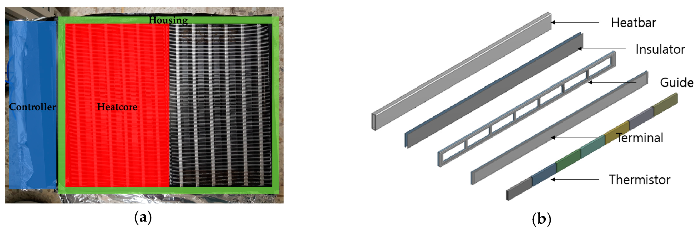
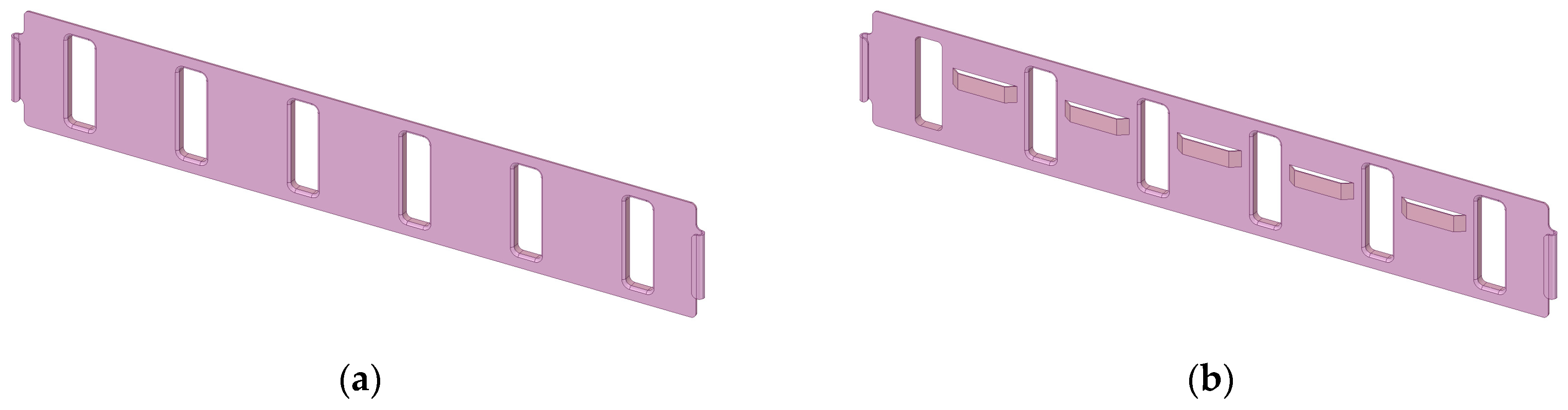
2.1. Heater Design

The high-voltage PTC heater for electric vehicles used in this study consisted of a controller, housing, and two heat cores, as shown in Figure 1a. The overall size of the heater is 330.0 mm (W) × 230.0 mm (H) × 22.0 mm (D), and the size of the heater module without the controller is 265.5 mm (W) × 215.0 mm (H) × 22.0 mm (D). A heat core consists of six heat rods and a radiator fin. The cross-sectional size of each heat rod is 16.7 mm × 5.1 mm, and the radius of the heat rod corner is 1.0 mm. The inside of a heat rod consists of a heatbar, an insulator, a terminal, a guide, and a PTC thermistor, as shown in Figure 1b. The heatbar serves to protect the inside of the heat rod from external shocks and water leaks from vehicle accidents, and the insulator prevents the current flowing into the PTC thermistor from exiting the outside. The guide secures the position of the PTC thermistor and the PTC thermistor is the main heating source of the PTC heater. Each heat rod uses seven PTC thermistors. The PTC heaters were divided into an initial prototype (Heater A) and an improved prototype (Heater B) according to the fin shape and design variables. Heater A was the basic model of the geometric design variables used in this study. It used a plate-shaped radiator fin and a PTC element that generated heat at 172 °C [11]. Heater B used a PTC element that generated heat at 188 °C in the heat rods, and it used a modified louver shape in the radiator fin. Otherwise, its specifications were the same as those of Heater A.
The radiator fins used in this study are shown in Figure 2. Their dimensions were 130.0 mm (W) × 21.5 mm (H) × 3.2 (D) mm. Figure 2a is the plate fin, and it included a bending shape that creates a fin pitch of 1.8 mm on both sides of the fin. Structurally, one radiation fin was inserted after six heat rods, each with a fin thickness of 0.3 mm. Figure 2b shows the modified louver-shaped fin. The size of the modified louver shape was 9.0 mm (W) × 1.2 mm (H) × 3.0 mm (D). It was configured so that the air that enters the modified louver fin was dispersed upward and downward, or passed through it in the direction of the heater’s thickness and created turbulence. In a normal louver fin, the flow of the air entering the front of the heater is dispersed to the upper or lower fin by the angle of the louver shape. This causes turbulence and facilitates heat transfer of the radiator fin, but it also has the disadvantage of reducing the free flow area of the air. As the radiator fin of an electric vehicle PTC heater must have a lightweight design in order to increase the single-charge travel distance, it tends to gradually become thinner. Therefore, the durability, mass production, and ease of assembly of the radiator fin must be considered comprehensively during its design. Table 1 shows the design specifications for each heater.

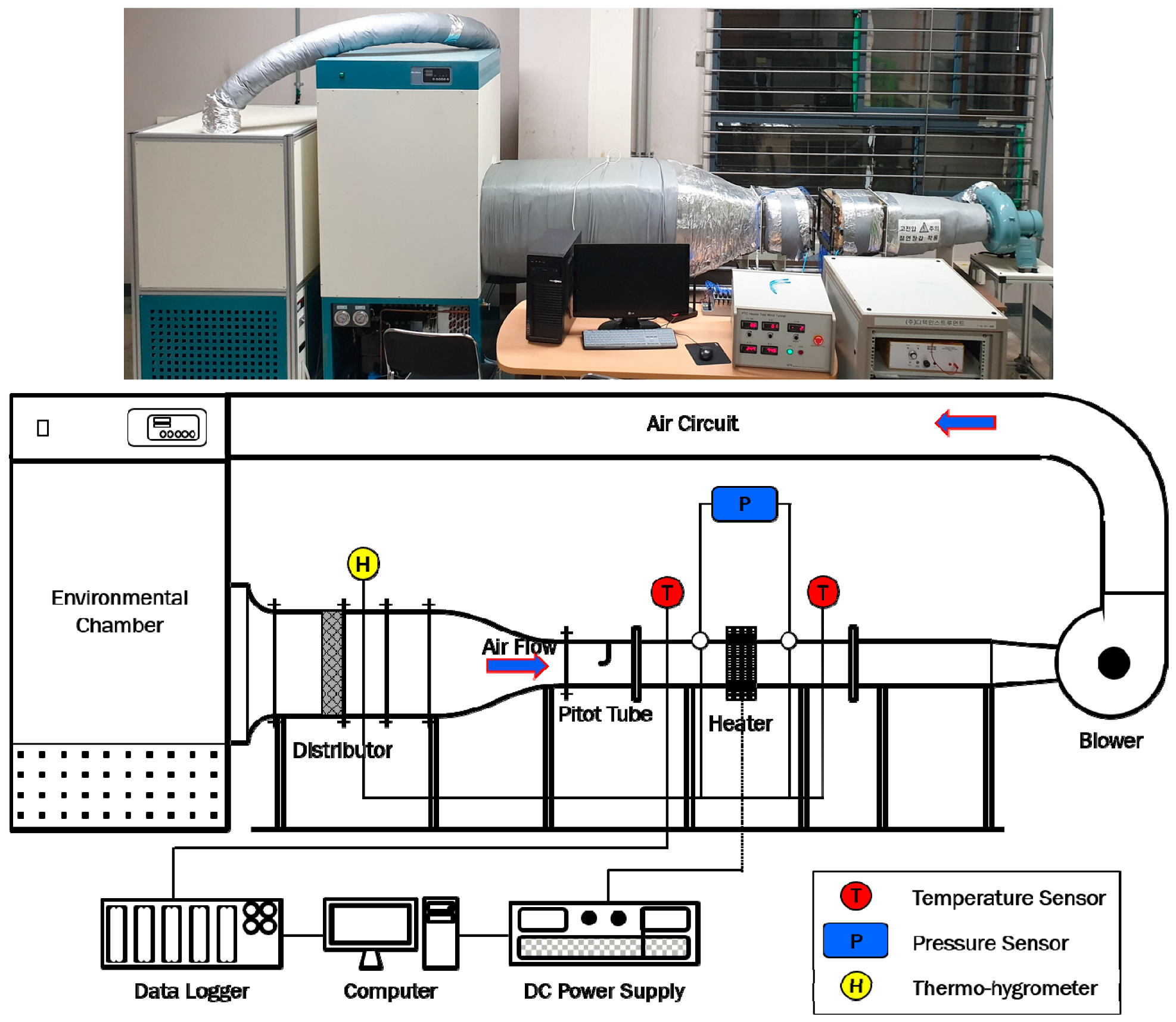
2.2. Experiment Setup and Method

An environmental chamber, a wind tunnel, a power supply, and data acquisition unit were included in the experimental apparatus used in this study to test the electric vehicle high-voltage PTC heaters, as shown in Figure 3. The wind tunnel consisted of a closed loop, and the blowers were turbo fan types with a maximum volume flow rate of 5 m3/min. The inside air velocity deviation was ± 1.0% at 1.5 m/s, and the turbulence coefficient was ± 1.0% at 1.5 m/s. To measure the air side temperature of the PTC heater, 6 K-type thermocouples were installed on the front end of the flow entering the heater, and 54 were installed on the rear end. These thermocouples had measurement error of ± 0.1%. The pressure drop was measured by pressure sensors connected to four holes in the front and rear ends of the PTC heater test part, and these had an error of ± 0.14%. The humidity was measured by a thermo-hygrometer on the rear end of the distributor, and it had an error of ± 1.5% based on relative humidity. The high-voltage current of the PTC heater was supplied by a DC power supply with 500 V/30 A, and it was controlled by general purpose interface bus communication. All data were collected and processed by a data logger. All the sensors and measuring instruments used in the experiment were pre-calibrated. Table 2 shows the specifications of all the experimental equipment.
To ensure a steady state on the air side during the experiments, the average temperature change measured over the course of 1 min at the PTC heater rear end was maintained at less than ± 1%, and the flow change was maintained at less than ± 5%. The experiments were performed under the normal PTC heater performance evaluation conditions comprising an inflow temperature of 0 °C, inflow rate of 300 kg/h, and input voltage of 330 V. After the steady state was reached, the data were collected at 1 s intervals for 10 min. The collected data were analyzed according to the performance evaluation criteria as follows. The heating capacity is an index that judges whether the interior of the vehicle can be adequately heated under the operating conditions of the electric vehicle heating system. It is expressed by Equation (1).
Q P T C = m ˙ C p ( T o T i ) .
Efficiency is an index that expresses the output versus input in terms of the ratio of the heating capacity to the current used by the PTC heater.
η = m ˙ C p ( T o T i ) V I .
Heating density is an important index that takes into account the weight of the heater in an electric vehicle, which affects the single-charge travel distance. The heating density is expressed as the heating capacity divided by the weight of the heater.
ρ = m ˙ C p ( T o T i ) W h e a t e r .

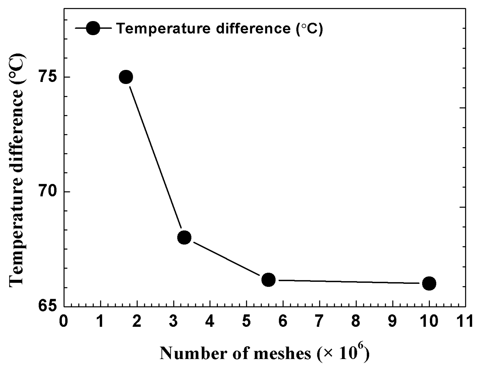
2.3. Physical Modeling

A physical fin shape was designed, as shown in Figure 4a, to obtain reliable PTC heater thermal flow analysis results and to predict the heating performance according to the fin shape. The size of the physical fin shape was 10.5 mm × 22.0 mm. The size of the modified louver varied according to the shape variables. The depth of the louver (Ld) was 3 mm. Table 3 shows detailed information on the radiator fin physical models according to changes in the shape variables.
The simulation domain is as shown in Figure 4b, and the inlet and outlet boundary conditions were set according to the flow direction. The housing was replaced with walls after changing the shape. The simulation domain was set to include a 1/4 PTC thermistor, and the overall size of the heat generation part of the heater was 1/336. For the rest of the boundary conditions of the simulation domain, the shape characteristics of the heater were considered, and symmetry and periodic boundary conditions were used. To obtain the direction of the air flowing into the inlet, an upstream region was formed, and its length was set at 22 mm (equal to the heater depth). To prevent backflow, the length of the downstream region was set at 44 mm (twice the heater depth and twice that of the upstream region). The temperature of the PTC element was set at the target design temperature of 188 °C, and the air was assumed to be incompressible ideal gas. The numerical analysis density function was set to change according to the temperature. The physical properties of the components of the heater are shown in Table 4.

2.4. Mathematical Background and Boundary Condition

In this study, the commercial finite volume method program Fluent (ver. 19.2) was used to perform the heat flow analysis. The flow was three-dimensional, incompressible, steady-state, and turbulent. The effects of radiative heat transfer were not considered. To perform the steady state numerical analysis, the Reynolds-averaged Navier–Stokes equation and a simple algorithm were used. The resulting continuity, momentum, and energy equations are as follows.
Continuity equation:
ρ u i x i = 0 .
Momentum equation:
( ρ u i u j ) x j = p x i + x j [ μ ( u i x j + u j x i 2 3 δ i j u l x l ) ] + x j ( ρ u ¯ i u ¯ j ) ,
where
ρ u ¯ i u ¯ j = μ t ( u i x j + u j x j ) 2 3 ( ρ κ + μ t μ κ x κ ) δ i j .
Energy equation:
x i ( u i ( ρ E + P ) ) = x i ( k e f f T x i ) .
This study used the k-ε realizable model, which is a modified k-ε and classical turbulence model provided by Fluent. The k term of the k-ε realizable model is the same as that in the standard k-ε model. However, in the case of the ε term, the production term and constant were modified to clarify the effects of spectral energy transfer. These changes were made to focus on the distinction in the temperature distribution according to the heat transfer from the fin and heat rods to the air side. The following transport equation of the k-ε realizable model was used.
Transport equation:
x j ( ρ κ u j ) = x j [ ( μ + μ t σ κ ) k x j ] + G k + G b ρ ε Y M + S k ,   and
x j ( ρ ε u j ) = x j [ ( μ + μ t σ ε ) ε x j ] + ρ C 1 S ε ρ C 2 ε 2 k + ν ε + C 1 ε ε k C 3 ε G b + S ε .
The enhanced wall treatment was used as the wall function. As a result, a mesh was formed so that the y+ value of the surface was as close to 1 as possible.
Most of the flow fields and heater components consisted of hexagonal meshes, and part of the flow fields where it is difficult to produce hexagonal meshes were consisted of tetrahedral mesh by inflation method. To ensure the reliability of the heat flow analysis, the P1 model was used to verify the independence of the meshes in Figure 5, and it was found that approximately 5.6 million meshes were appropriate considering the performance and computation speed of the computer. To ensure the reliability of the analysis model, the P1 model was also compared to the experiment results of the heating performance from Kang et al. when using the same geometric design variables [11]. The error was found to be 5.7%. The heat generation temperature of the PTC element was set to 188 °C, and a numerical analysis was performed on the P1 model under standard conditions. It showed a heating performance of 5.9 kW, and it was confirmed that the normal plate-shaped radiator fin is not suitable for a 6 kW class PTC heater.

3. Results and Discussion

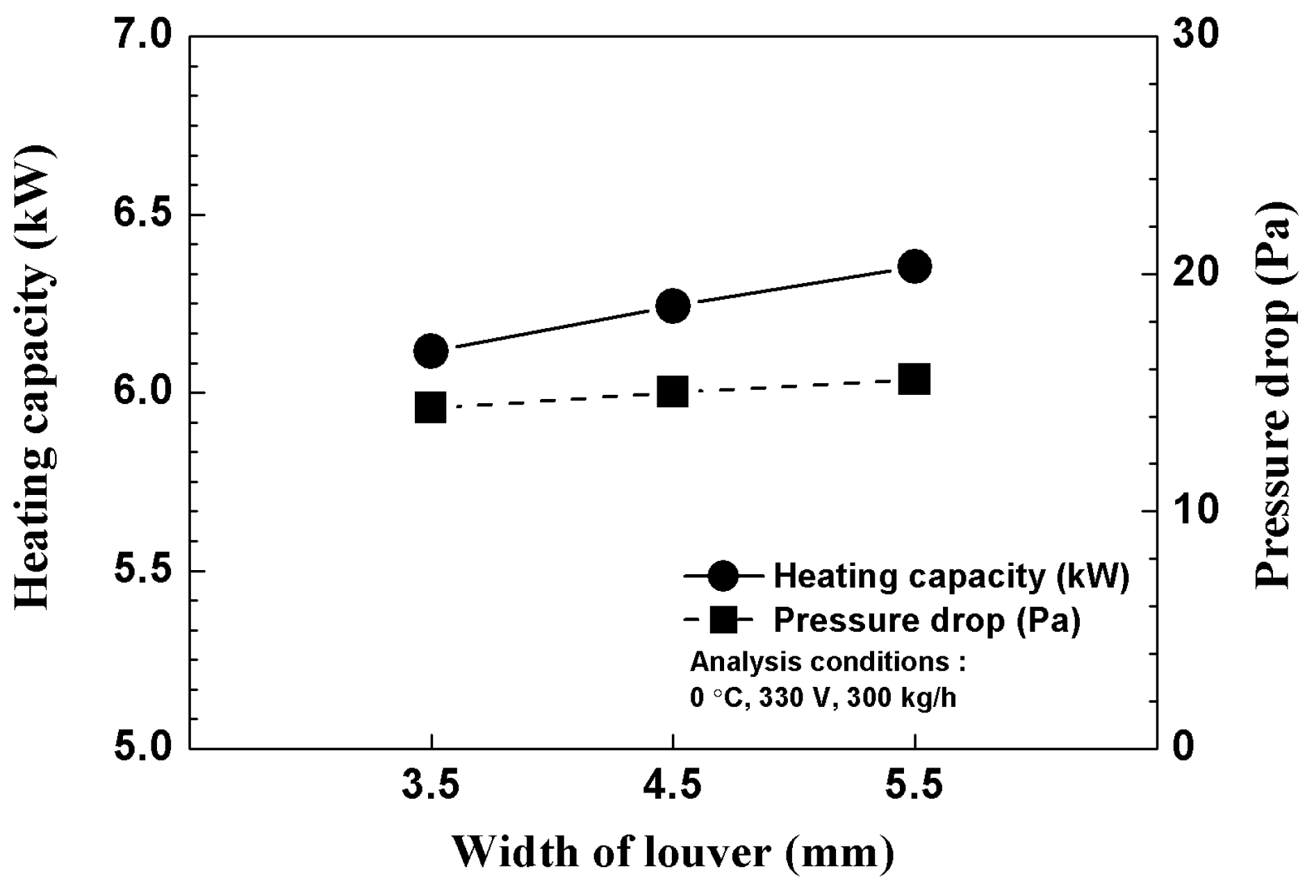
3.1. Heating Performance Enhancement of Various Geometric Parameters for the Modified Louver Fin

Figure 6 shows the heating capacity and pressure drop according to changes in the width of the louver fin shape. The heating capacity increased by an average of 0.12 kW each time the width of the louver fin increased by 1 mm, and the highest value was observed at a louver fin width of 5.5 mm. This is because the air turbulence effect was facilitated and the heat transfer performance improved as the width of the louver increased. The differential pressure increased by an average of 0.61 Pa each time the width of the louver increased by 1 mm. As the differential pressure increased, so did the heat transfer effect. The distance between the heat rods and the heater, as well as the ease of manufacturing were considered as mandatory requirements in this study, toward the goal of manufacturing a high-capacity PTC heater, and the obtained values were applied to the heater design. Thus, the resulting heater was built with the maximum possible louver width.
Figure 7 shows the heating capacity and pressure drop according to the position of the louver fin shape. The heating capacity increased by an average of 0.05 kW when the louver fin shape was moved back by 3 mm, and it reached its largest value (6.27 kW) at a position of 8 mm. This is because the air that flowed into the front end encountered turbulence caused by the louver shape, and the heat transfer performance improved. The differential pressure was reduced by an average of –0.17 Pa when the position of the louver shape was moved back by 3 mm. Given that the position of the louver shape had little effect on the differential pressure, the louver was positioned on the front of the heater considering the thickness of the PTC heater.
Figure 8 shows the heating capacity and pressure drop according to the height of the louver fin. The heating capacity had a maximum value of 6.24 kW when the height of the louver fin was 0.9 mm. When the height of the louver fin was 0.6 mm and 1.2 mm, the height of the louver was reduced by 2.8% and 2.9% respectively compared to when the height was 0.9 mm. This is because at a louver shape height of 0.9 mm, the louver is located exactly in the middle of the air layer existing between the fins. Therefore, the incoming air is evenly divided up the top and bottom of the louvered fin shape and the heat transfer capability is improved through efficient contact with the radiation fin. However, if the height of the louver shape is 0.6 mm and 1.2 mm, the air layer expanding between the fins is asymmetrically divided, which creates an uneven flow distribution above and below the louvered shape, thereby reducing the turbulent flow generation effect. The differential pressure had a maximum value of 15.01 Pa when the position of the louver shape was 0.9 mm. When the height of the louver shape was increased or decreased by 0.3 mm, the differential pressure was reduced by an average of 3.4%, and the height of the louver shape was found to have a predominant effect on the differential pressure. On the other hand, the average influence of louvered shape angle or position design variables on differential pressure was around 1.1%. Therefore, it appears that it is necessary to select heater design variables that will lower the pressure differential of the heater.
Figure 9 shows the heating capacity and pressure drop according to the change in the angle of the louver fin. When the angle is 90° or greater, the ease of manufacturing with metallic patterns is reduced. Therefore, this design variable was set as 30°, 50°, and 70°. When the angle of the louver fin was increased from 30° to 50°, the heating capacity increased by 1.18%. When the angle was increased from 50° to 70°, the heating capacity increased by 0.3%. It is believed that as the angle increased, the flow toward the high-temperature heat rods increased, and therefore, the heat transfer performance improved. The differential pressure increased by an average of 0.17 Pa each time the angle of the louver shape increased by 20°, and it was found that the angle had a slight effect on the differential pressure. When the louver angle was 50°, the increase in the heating capacity versus the increase in the differential pressure was the highest. Therefore, a louver fin angle of 50° was found to be suitable for the heater design.

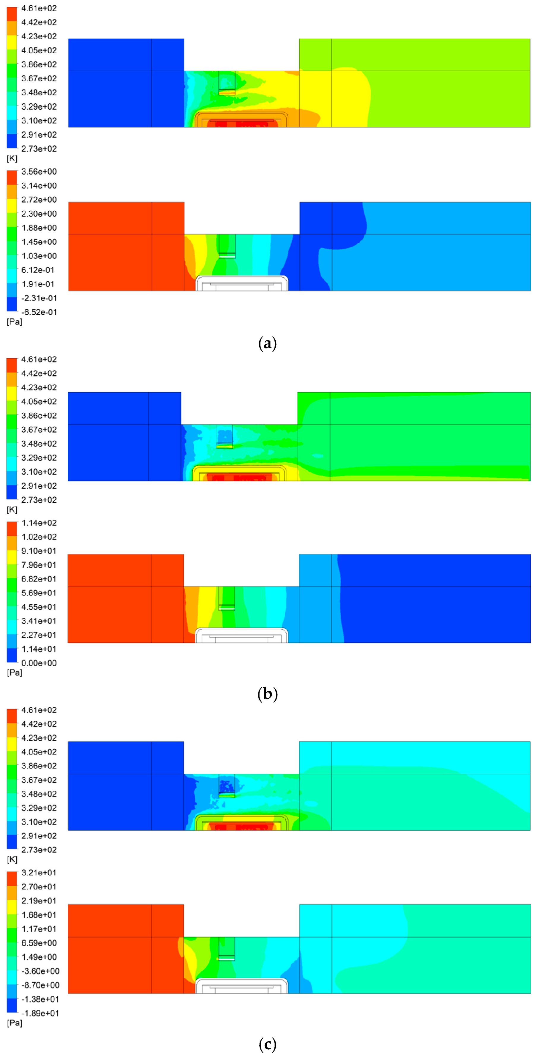
3.2. Numerical Analysis Results for Improved Prototype

Based on the results of the numerical analysis and considering the improvement in heat transfer performance versus the pressure differential, the durability of the fin, ease of manufacturing, etc., the geometric design variables that were ultimately used in the improved prototype were as follows: A louver fin shape width of 4.5 mm, position of 8 mm, height of 1.2 mm, and angle of 50°. A heat flow numerical analysis was performed to predict the pressure differential and heat transfer performance according to changes in the improved flow of the prototype.
The L10 model (improved prototype) was analyzed according to the change in the flow rate from 100 kg/h to 500 kg/h at a voltage of 330 V and an inflow air temperature of 0 °C. The pressure and temperature contours are shown in Figure 10. As the flow rate increased, the heat transfer by the heat rods decreased, and the heat transfer by the fin increased. The improvement in heat transfer performance caused by the modified louver shape was confirmed for all flow rate change conditions. As the flow rate increased, an insulation effect due to the insulator was evident, and the temperature gradient of the fin increased. A differential pressure was observed due to the inclined surface of the modified louver shape. At 500 kg/h, which corresponds to severe conditions for differential pressure performance, the largest pressure of 51.0 Pa occurred locally between the front and the rear ends of the heat rods. The rear housing had a predominant effect on the differential pressure because they caused vortex.
Figure 11 shows the heating performance and differential pressure analysis results for the L10 model according to the flow rate changes at an input voltage of 330 V and an inlet air temperature of 0 °C. The heat transfer amount increased according to the increase in the flow rate, but a reduction was noted in the extent of the increase. Under standard conditions, the heating capacity was 6.39 kW. At 100 kg/h, which corresponds to severe conditions for the heater, the heating capacity was 3.57 kW. The amount by which the pressure drop increased tended to rise according to the increase in the flow rate. At a standard flow rate of 300 kg/h, it was 14.48 Pa. At the maximum flow rate of 500 kg/h, the pressure drop value increased to a maximum of 30.35 Pa. Due to the increase in flow rate, the heat transfer increased by an average of 23.5%, and the pressure drop increased by an average of 76.70%. Even allowing for the ideal heat transfer conditions assumed in the numerical analysis, it is expected that the design variables of the L10 prototype can be used to build a heater that operates at 6 kW or more.

3.3. Experimental Results and Discussion

An improved prototype for a 6 kW class high-voltage PTC heater (Heater B) for use in an electric vehicle was built based on the geometric design variables of the L10 model, and its performance was tested under standard conditions (0 °C, 300 kg/h, and 330 V). The results are shown in Table 5.
Heater B had a heating capacity of 6.05 kW and showed that a 6 kW class heater could be easily designed and implemented. Compared to the heating capacity of Heater A (5.23 kW), the heating capacity of Heater B improved by 15.7%. This is considered to be due to the effects of the increased heat generation temperature of the PTC element and the turbulence created by the louver fin. The improved prototype was a high-performance heater design with a pressure drop of 18.3 Pa, an efficiency of 98.0%, and a heating density of 3.8 kW/kg. Compared to the results of the numerical analysis on the heater, the heating performance prediction error was low (5.62%). The pressure drop was predicted to be lower by 3.82 Pa, but this was because the numerical analysis considered a controller through which fluid could not pass.

5. Conclusions

This study performed a heat flow numerical analysis of the geometric shape variables of a modified louver fin based on an initial prototype in order to develop a 6 kW class high-capacity PTC heater for electric vehicles. A final modified louver fin shape was presented with consideration given to the heat transfer performance, differential pressure, and ease of manufacturing. An improved prototype was built using the proposed modified louver fin shape. Heating performance tests were performed on the improved prototype under standard conditions, and the results can be summarized as follows.
  • A reliable heat flow numerical analysis with a heating performance prediction error of 5.62% was used to perform comparative analysis on the heating capacity and pressure drop according to the geometric design variables (width, position, height, and angle) of the modified louver fin.
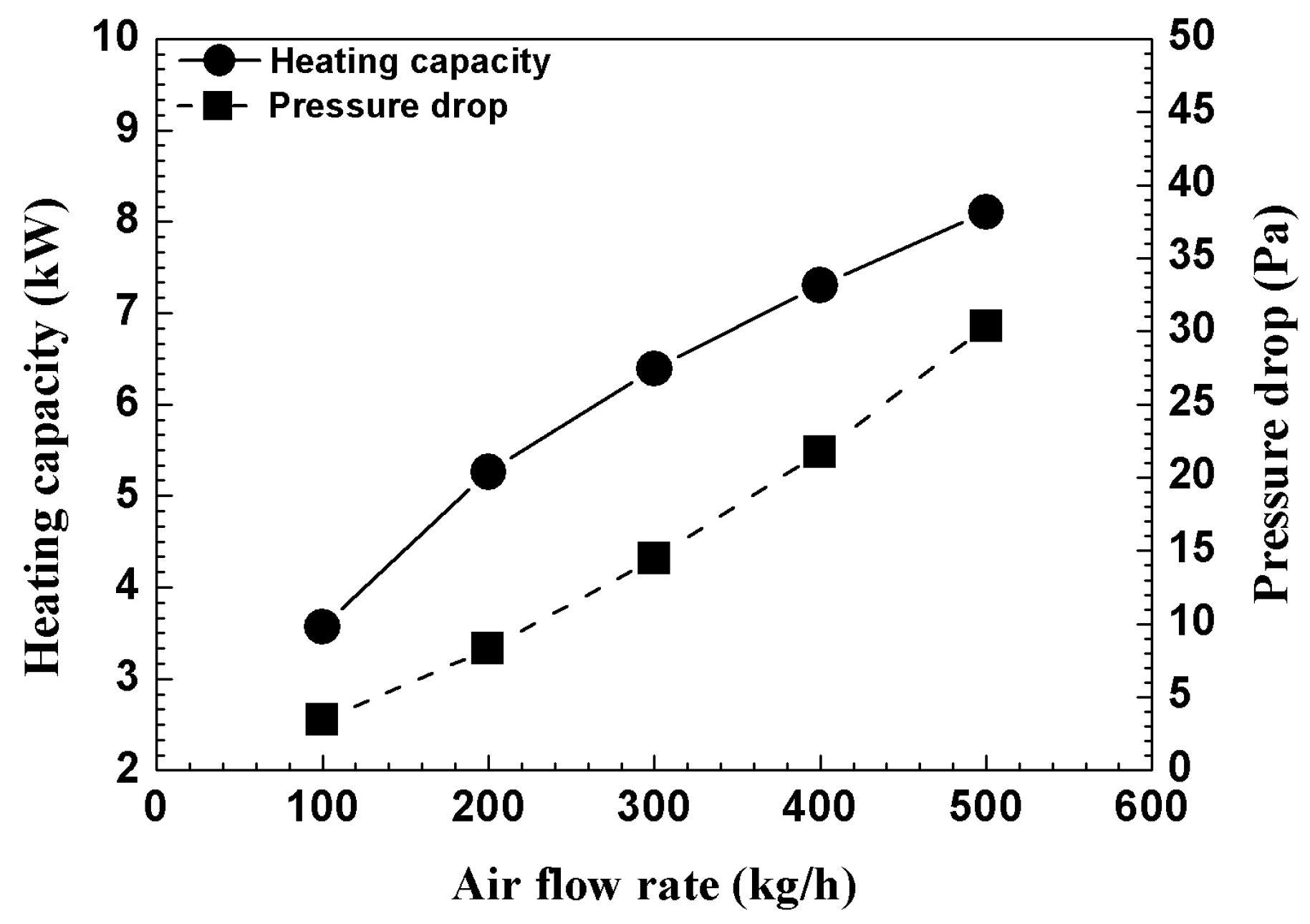
  • The heat transfer and pressure drop characteristics of the modified louver fin were analyzed under changed flow rate conditions. As the flow rate increased, the heat transfer increased by an average of 23.5%, and the pressure drop increased by an average of 76.70%. At 100 kg/h, which corresponds to severe conditions for the heater, a high heating capacity of 3.57 kW was noted.
  • Based on the numerical analysis results, an improved prototype was built, and its heating performance was tested. The results showed a heating performance of 6.05 kW, an efficiency of 98.0%, a pressure drop of 18.3 Pa, and a heating density of 3.81 kW/kg. The heating performance improved by 15.7% compared to the initial prototype.
The results of this study can be used as basic data in the future to build high-capacity heaters of 6 kW or more and design radiator fins through reliable numerical analysis. In the future, these designs will be optimized using performance evaluation criteria such as f and j factors.

Author Contributions

Experimental/numerical analysis and writing, M.H.P.; Evaluation and review, S.C.K.

Funding

This research was conducted as part of the Energy Technology Development Project sponsored by the Ministry of Trade, Industry and Energy (South Korea). The additional support received from Korea Automotive Technology Institute and Donga High Tech Company is greatly appreciated.

Conflicts of Interest

The authors declare no conflict of interest.

Nomenclature

C p Specific heat (J/kg∙K)
D Depth (mm)
H Height (mm)
I Current (A)
m ˙ Mass flow rate (kg/s)
Q Heating capacity (W)
T Temperature (°C)
V Input voltage (V)
W Width (mm)
W h e a t e r Weight of heater (kg)
η Energy efficiency (%)
ρ Heating density (kW/kg)
Subscripts
aAngle
dDepth
hHeight
iInlet
oOutlet
pPosition
wWidth

References

  1. Kwon, C.K.; Kim, M.S.; Choi, Y.G.; Kim, M.S. Performance evaluation of a vapor injection heat pump system of electric vehicles. Int. J. Refrig. 2017, 74, 138–150. [Google Scholar] [CrossRef]
  2. Lee, D.Y.; Cho, C.W.; Won, J.P.; Park, Y.C.; Lee, M.Y. Performance characteristics of mobile heat pump for a Large passenger electric vehicle. Appl. Therm. Eng. 2013, 50, 660–669. [Google Scholar] [CrossRef]
  3. Cho, C.W.; Lee, H.S.; Won, J.P.; Lee, M.Y. Measurement and evaluation of heating performance of heat pump systems using wasted heat from electric devices for an electric bus. Energies 2012, 5, 658–669. [Google Scholar] [CrossRef]
  4. Kim, K.Y.; Kim, S.C.; Kim, M.S. Experimental studies on the heating performance of the PTC heater and heat pump combined system in fuel cells and electric vehicles. Int. J. Automot. Technol. 2012, 13, 971–977. [Google Scholar] [CrossRef]
  5. Lee, D. Experimental study on the heat pump system using R134a refrigerant for zero-emission vehicles. Int. J. Automot. Technol. 2015, 16, 923–928. [Google Scholar] [CrossRef]
  6. Wang, Z.; Wei, M.; Guo, C.; Zhao, M. Enhance the heating performance of an electric vehicle AC/HP system under low temperature. Energy Procedia. 2017, 105, 2384–2389. [Google Scholar] [CrossRef]
  7. Shin, Y.H.; Sim, S.; Kim, S.C. Performance characteristics of a modularized and integrated PTC heating system for an electric vehicle. Energies 2016, 9, 18. [Google Scholar] [CrossRef]
  8. Shin, Y.H.; Ahn, S.K.; Kim, S.C. Performance characteristics of PTC elements for an electric vehicle heating system. Energies 2016, 9, 813. [Google Scholar] [CrossRef]
  9. Park, M.H.; Kim, S.C. Heating performance characteristics of high-voltage PTC heater for an electric vehicle. Energies 2017, 10, 1494. [Google Scholar] [CrossRef]
  10. Park, M.H.; Kim, S.C. Effects of geometric parameters and operating conditions on the performance of a high-voltage PTC heater for an electric vehicle. Appl. Therm. Eng. 2018, 143, 1023–1033. [Google Scholar] [CrossRef]
  11. Kang, H.S.; Sim, S.; Shin, Y.H. A numerical study on the light-weight design of PTC heater for an electric vehicle heating system. Energies 2018, 11, 1276. [Google Scholar] [CrossRef]
Figure 1. 6 kW class high-voltage positive temperature coefficient (PTC) heater and heat rod design: (a) PTC heater design; (b) components of heat rod.
Energies 12 02900 g001
Figure 2. Radiation fin designs: (a) Plate fin; (b) modified louver fin.
Energies 12 02900 g002
Figure 3. Photo and schematic diagram of the PTC heater experimental apparatus.
Energies 12 02900 g003
Figure 4. Simulation model with boundary conditions: (a) Physical fin design; (b) simulation domain.
Energies 12 02900 g004
Figure 5. Mesh independence analysis results.
Energies 12 02900 g005
Figure 6. Heating capacity and pressure drop variations for different widths of the modified louver.
Energies 12 02900 g006
Figure 7. Heating capacity and pressure drop variations as per the position of the modified louver.
Energies 12 02900 g007
Figure 8. Heating capacity and pressure drop variations for different heights of the modified louver.
Energies 12 02900 g008
Figure 9. Heating capacity and pressure drop variations for different angles of the modified louver.
Energies 12 02900 g009
Figure 10. Temperature (up) and pressure drop (down) contours at different mass flow rates (a) 100 kg/h, (b) 300 kg/h, and (c) 500 kg/h.
Energies 12 02900 g010
Figure 11. Variations in heating capacity and pressure drop for the L10 model (improved prototype).
Energies 12 02900 g011
Table 1. Specification of positive temperature coefficient (PTC) heaters A and B.
ParameterHeater A (Initial Prototype) Heater B (Improved Prototype)
Total heater size (mm3)330.0 (W) × 230.0 (H) × 22.0 (D)
Heater module size (mm3)265.5 (W) × 215.0 (H) × 22.0 (D)
Weight (kg)1.591.59
Input voltage (V)330330
Fin typePlateModified louver
Fin pitch (mm)1.81.8
Fin thickness (mm)0.30.3
Number of fins112112
PTC thermistor temperature (°C)172188
Table 2. Specification of PTC heater experimental apparatus.
ComponentSpecification
Thermocouple (K-type)± 0.1% (−60–200 °C), inlet 6 points, outlet 54 points
Diff. pressure gauge (Setra)± 0.14% (0–125 Pa)
Pitot tube (Samdukeng)Φ3.2 × 150 mm
Thermo-hygrometer (Kimo)± 0.25% (0–50 °C), ± 1.5% (5%–95% RH)
Data acquisition system (NI)60 channels, 9–30 V @ 15 W
Blower (Dongkun)Turbo fan, max volume flow rate: 5 m3/min
Table 3. Specifications of the physical model.
ModelFin TypeLwLpLhLa
P1 (initial prototype)Plate----
L1Modified louver4.5110.950°
L2Modified louver3.5110.950°
L3Modified louver5.5110.950°
L4Modified louver4.580.950°
L5Modified louver4.5140.950°
L6Modified louver4.5110.650°
L7Modified louver4.5111.250°
L8Modified louver4.5110.930°
L9Modified louver4.5110.970°
L10 (improved prototype)Modified louver4.581.250°
Table 4. Thermal properties of the parts.
PartDensity
(kg/m3)
Specific Heat
(J/kg∙°C)
Thermal Conductivity
(W/m∙°C)
PTC thermistor389077936
Guide120010500.23
Terminal8470380116
Insulator0.00240.870.8
Heatbar2700900218
Fin2719871202.4
Table 5. Heating performance of PTC heater B (improved prototype).
ParameterHeater B (Improved Prototype)
Input current (A)18.63
Power consumption (kW)6.18
Temperature difference (°C)72.3
Heating capacity (kW)6.05
Pressure drop (Pa)18.3
Energy efficiency (%)98.0
Heating density (kW/kg)3.81

