Abstract
This paper proposes an innovative operation strategy to extend the acceptance of EVC (Electric Vehicle Charger) and RES (Renewable Energy Resource) in LVDS (Low Voltage Distribution System) by introducing an ESS (Energy Storage System). In conventional LVDS, the load and RES capacity are designed not to exceed the pole transformer capacity. However, when the ESS is connected to the end of LVDS and the bidirectional power flow becomes possible, the linkable capacity of the load and renewable energy can be improved up to twice the capacity of the pole transformer. In addition, even though the power consumption of the load and the power generation of RES exceed the pole transformer capacity, it is possible to maintain the feeder capacity and grid voltage within the allowable limit by the appropriate operation of the ESS. The simulations are performed in the environment of PSCAD/EMTDC, and the ability of the proposed strategy is assessed and discussed.
1. Introduction
The Korean government actively takes actions of the energy policy, by which the capacity of RES (Renewable Energy Resource) is to increase up to 20% of all energy sources by the year 2030. Along with the Korean government policy, Jeju Special Self-Governing Province of Korea executes a policy (so called “Carbon Free Island Jeju by 2030” [1,2]) of distributing 2 GW of RES and converting all vehicles into EV (Electric Vehicle) by the year 2030. In Korea, the RES capacity is not only increasing but also the fast/slow charger in buildings, homes, and public places are rapidly spreading. As the installation of the slow charger for the EV users in the individual customer becomes dominant in the LVDS (Low Voltage Distribution System), it begins to act as a malicious load in LVDS designed according to transformer capacity. Therefore, a special caution is required to increase the inflow rate of the EV charger in the customer not to cause a low voltage in the secondary feeder as well as not to violate the capacity limit of the pole transformer. In addition, when it comes to the increase of RES capacity in the LVDS, it also needs a caution to prevent the overvoltage in the secondary feeder.
Traditionally, in order to solve aforementioned problems, the first reinforcement action is to replace the pole transformer by a larger capacity, and to expand the secondary feeder. The second reinforcement action is to install pole transformers closer to EVs. However, the traditional approaches require time and high cost. Thus, it is understandable that the traditional approaches are not suitable for future electric networks [3,4]. Therefore, this paper proposes an innovative operation strategy of the ESS (Energy Storage System) that is to contribute to increase the capacity of EVC (Electric Vehicle Charger) and RES in the LVDS without reinforcement of the existing facilities.
An ESS is used in various forms from the transmission system to distribution system and microgrid such as frequency regulation in distribution substations, power stabilization of fluctuating RES, peak-cut for charging at light load and discharging at heavy load, and emergency power generation, etc., [5,6,7,8]. In particular, the introduction of the ESS in a LVDS without voltage regulation can have a number of advantages. In Table 1, the authors of [9,10] proposed the voltage regulation method by connecting the ESS to the PV (Photovoltaic) installation point, and in [11] the authors proposed the methods for sizing and siting of RES, EV station, and ESS. The authors of [12] also addressed the economic effects of an ESS in LVDS. However, as the capacity of EV and renewable energy is continuously increased in LVDS, research is needed to increase the capacity that can be connected using existing facilities as well as voltage issues.

Table 1.
Literature survey on applications of an ESS (Energy Storage System) in LVDS (Low Voltage Distribution System).
In the proposed strategy, in order to solve the problems of voltage drop/rising and feeder capacity by introducing a large number of EV chargers and RES in the LVDS, an advantage of ESS bidirectional power flow is considered at the end of the secondary feeder in order to maintain the voltage and the power within allowable limit (voltage: 220 ± 6%, feeder capacity: pole transformer rated capacity). The proposed strategy shows its ability to expand the capacity of EV and RES up to twice the capacity of the pole transformer while the voltage and feeder capacity are maintained with allowable limit. Its ability is assessed and discussed by the simulation consisting of an ESS, PV, EVC, and load in the environment of PSCAD/EMTDC software.
The paper is organized as follows: Section 2 presents the necessity of introducing an ESS for power stabilization and the innovative operation algorithm while Section 3 presents the complete model of LVDS in PSCAD/EMTDC; Section 4 derives the validity of the proposed strategy from the simulation and the Performance Index (PI) is discussed in Section 5. Finally, in Section 6 conclusions are drawn.
2. An Innovative Operation Strategy of Power Control ESS for Capacity Expansion
2.1. Necessity of Introducing Power Control ESS for Capacity Expansion of EV and RES
The operation schemes of the existing LVDS are based on the unidirectional power flow. However, when the RES is connected to the LVDS, the reverse power flow is supplied unlike the existing system. This reverse power flow can cause power quality problems such as voltage sag and swell, harmonics, etc., in existing systems [13]. In particular, voltage control is one of the important issues in power distribution system including LVDS.
In general, the voltage of the system is changed by the current having the variation value and the line impedance having the fixed value. When a lot of power flows to the load side, the voltage drop is intensified and when the current flows to the system side by the RES, the voltage rise is intensified. According to the system characteristics, when installing multiple EVCs, problems such as under voltage and exceeding the rated capacity of the pole transformer may occur as shown in Figure 1.
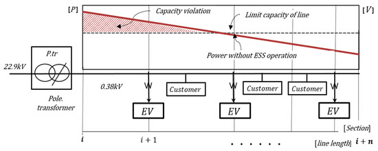
Figure 1.
Voltage of LVDS by the unidirectional power flow.
Figure 2 shows the power control ESS by using bidirectional power flow to expand acceptance and to control the voltage. Since the pole transformer and the ESS share the power flowing in the secondary feeder, the voltage drop and rise due to the line impedance can be reduced. In addition, the connection capacity of EVC and RES can be increased without exceeding the feeder capacity. Therefore, this paper proposes a power sharing scheme by ESS operation to solve the voltage and feeder capacity problems when a large number of EVC and RES are connected to the LVDS.
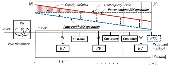
Figure 2.
Voltage of LVDS by the bidirectional power flow.
2.2. Power Control ESS for Capacity Expansion
In a LVDS, the voltage may vary depending on the EV charging and the amount of RES. Figure 3 shows the voltage and feeder capacity issues resulting from EV charging and RES. If RES is high during the day, overvoltage may occur in the customer, and under voltage may occur in the customer when the EV charging is utilized in the evening. In such a situation, the proper charging/discharging operation of the ESS can solve the voltage and feeder capacity problems.
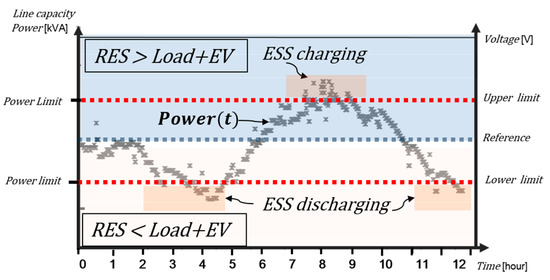
Figure 3.
Voltage drop and rise issues.
Therefore, this paper proposes a power stabilization method to regulate the voltage and to expand the connection capacity by charging/discharging the ESS when the voltage is out of the upper/lower limit due to RES generation and EV charging. The concept of this strategy is shown in Figure 4 [14].
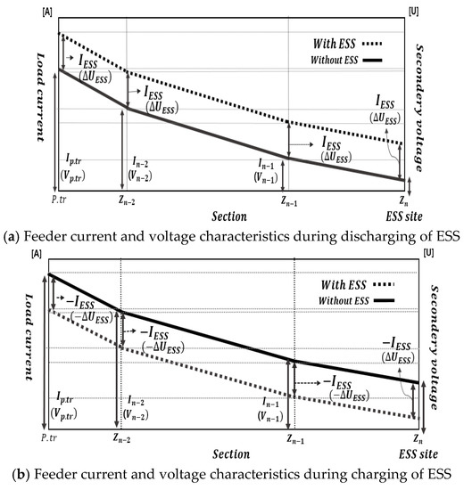
Figure 4.
Feeder current and voltage according to charging/discharging operation of the ESS.
The details of the proposed strategy are as follows. If all the power generated by RES flows to the grid side, the system voltage can exceed the upper limit (V > 233 V) as shown in Figure 4a. In such a situation, the ESS connected to the grid end is operated in the charging mode, and is operated to maintain the voltage within the allowable limit by distributing power flowing only to the grid side by the charging. In addition, when a large number of electric vehicles connected to the customer are charged, the voltage may be out of tolerance due to the voltage drop. In this situation, the ESS connected to the end of the grid is operated in the discharging mode, and the charging power of the EV is supplied by the grid and the ESS. Figure 4b shows the strategy of increasing the voltage drop by the EV charging through the discharge of the ESS. Through the discharge of the ESS, the voltages of the customers before the ESS installation point increase according to the discharging power of ESS, and as a result, the customer voltage outside the lower limit is kept within the allowable limit.
2.3. Operation Algorithm of Power Control ESS
(1) System model for operation of power control ESS
The ESS currently operating in the industrial field mainly focuses on economic operation, peak cut, and load shifting [15,16,17]. However, the ESS proposed in this paper focuses on the operation of complying with the system regulations such as the voltage and the feeder capacity while maximizing the acceptance of EVC and RES that can be connected to the LVDS. The configuration of the LVDS including the ESS, EV, and RES is shown in Figure 5. Here, the secondary feeder is divided into three sections so that voltage drop/rise can occur according to power consumption and power generation. In each section, the load is connected to consume power, and the PV and EV chargers are connected to the same point with the load to generate and consume the power. In the case of the ESS, it is connected to the end of the feeder, and various information such as the voltage and active power measured in each section of the feeder is transmitted to the ESS through communication to enable optimal operation.
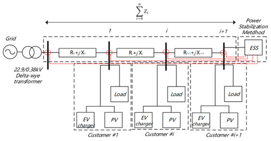
Figure 5.
Radial LVDS with multiple buses.
(2) Operation algorithm of power control ESS for expanding capacity
The existing ESS operation is proposed to operate according to the current and power state of the installation point. However, the operation strategy of the ESS proposed in this paper is operated to satisfy the voltage and feeder capacity of all sections within the allowable limit using the data collected at each point as shown in Figure 5. In a large scaled grid system having a small R/X ratio, the voltage is usually regulated by reactive power [18]. However, unlike the transmission line, the secondary feeder of the LVDS has a large R/X ratio. That is, in the transmission line, the reactance value is larger than the resistance value, so the voltage compensation effect by the reactive power is large, but in the low voltage distribution line with the small reactance value, the voltage compensation effect by the reactive power is not only small but also worsens the system power factor. Therefore, only the active power of the ESS is used for the acceptability expansion and voltage regulation.
Figure 6 shows the scheme of ESS operation to control voltage considering the margin. The power control scheme of the ESS first checks the system’s maximum current. Next, after analyzing the voltage characteristics at EV + heavy load and the voltage characteristics at the maximum power generation of the RES + light load from the pole transformer to the end section, the ESS is charged or discharged as much as the power out of the system’s acceptable capacity to maintain the voltage within the allowable limit.
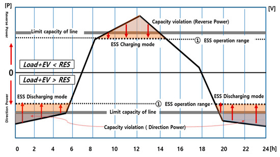
Figure 6.
ESS charging/discharging operation.
Figure 7 shows the operation algorithm of the power stabilization ESS that stabilizes the power by charging and discharging the ESS when the power from EV charging and RES generation exceeds the acceptable capacity of pole transformer.
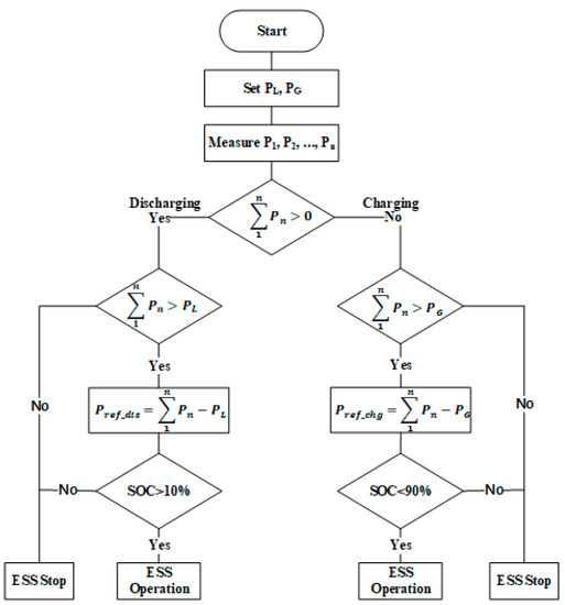
Figure 7.
Operation algorithm for the ESS.
In the algorithm, the charging and discharging mode, operation time, and operation capacity for the ESS are determined based on the data from the measurement point, and the ESS is operated stably within the SOC (State of Charge) range. Additionally, five alarm signals are used to determine each state in the algorithm. In this way, when the load capacity exceeds the pole transformer capacity, the ESS stabilizes the system in discharge state, and when the power of the RES exceeds the feeder capacity, the ESS stabilizes the system in charge state. The detailed algorithm operation procedure is as follows.
[Step 1] Determining of reference value (PL, PG) for the operation of power control ESS
The load in each section below the pole transformer is assumed to be equal, and then the load is increased until the voltage reaches the lower limit (0.94 PU). At this time, when the voltage of section 3 reaches to the lower limit, the measured active power in section 1 becomes the reference value (PL) for ESS discharging operation. In addition, for the charging operation of the ESS, the capacity of the RES of each section is assumed to be equal and a generated power of RES is increased until the voltage of the section 3 becomes upper limit (1.06 PU). At this time, when the voltage of section 3 reaches the upper limit, the power of section 1 becomes the reference value (PG) for ESS charging operation.
[Step 2] Determining the charging/discharging mode of the ESS
To determine the mode of the ESS, the direction of power at the measurement point must first be determined. The sign of power in the algorithm is determined as follows. It is assumed to be positive when the power flow towards the load side from the grid side and negative when the power flow towards the grid side from the load side. Then the charging/discharging mode of the ESS is determined according to the sign of the sum of the active powers measured at each point as shown in Equation (1). In other words, if the sum is a positive value, the power consumption of the load is greater than the generated power, and since the system voltage may drop below the lower limit, the signal α(t) becomes 1 and the ESS operates in discharging mode. If the sum is negative, it means that the generated power from RES is more than the power consumption of the load. Since the system voltage may be out of the upper limit, the signal α(t) becomes 0 and the ESS operates in charging mode.
where, Pi(t) is the active power of the i section, α(t) is a signal for the determination of charging/discharging mode of the ESS.
[Step 3] Determination of ESS output for the power control
Once the charging/discharging mode is determined, the operating time and output of the ESS should be determined. First, the operation time of the ESS in the discharging mode is determined according to the reference value PL obtained in [Step 1]. When the sum of the power measured in each section reaches to the reference value PL, the signal β(t) is activated and the ESS starts discharging operation as shown in Equation (4). If the signal β(t) is deactivated, that is, if β(t) = 0, the ESS stops. The discharging power of the ESS is determined by comparing the sum of the power measured in each section and the reference value PL as shown in Equation (3)
where Pdis_ref is the ESS discharging power, and β(t) represents the discharging operation start point of the ESS.
The operation time of the ESS in the charging mode is determined according to the reference value PG. In the charging mode when the power generation capacity of RES reaches the reference value PG, the signal γ(t) is activated as shown in Equation (4). The charging power of the ESS is determined by comparing the sum of the power for each section and the reference value PL in the charging mode as shown in Equation (5).
where Pchg_ref is the ESS charging power, and γ(t) represents the charging operation start point of the ESS.
[Step 4] Power stabilization of the ESS
Once the mode and output power for charging/discharging of the ESS are determined, the ESS stabilizes the system by sending or absorbing the active power of the ESS to stabilize the voltage.
[Step 5] SOC operation range setting
This step shows the ESS operation decision in either the charging or the discharging according to the SOC. That is, when the SOC of the ESS exceeds the upper limit set value due to the absorption of active power in the charging mode, the signal δ(t) is activated and the ESS stops operating. In addition, when the SOC of the ESS is under the lower limit set value due to the providing the active power to the load and EV charger in the discharging mode, the signal η(t) is activated and the ESS stops.
Table 2 shows how the five signals of the ESS used in the algorithm operate in each state.
Table 2.
Classification of operation signal of the ESS.
3. Modeling of the LVDS with ESS and RES
In order to verify proposed algorithm for the power stabilization of the LVDS with the ESS, the low voltage system with an EV charger, ESS, RES, and the control algorithm are modeled using PSCAD/EMTDC. Here, the RES which is used in LVDS is usually a PV system. Therefore, the model of RES uses a PV system.
Figure 8 shows the complete system consisting of pole transformer, feeder, load, PV, and ESS. The LVDS is a multiple bus radial distribution system composed of the load, EV charger, PV, and ESS connected to end of the secondary feeder. The secondary feeder uses the pi section model to simulate voltage drop and rise over distance. In the model, the power information measured in each bus is transferred to the ESS to determine the charging/discharging mode and the capacity.
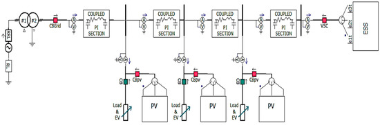
Figure 8.
Low voltage distribution system with an ESS.
3.1. Modeling of ESS
The power stabilization ESS consists of the battery that stores the electricity, the DC-DC converter that delivers power to charging/discharging to the battery, the inverter to convert power from AC to DC or vice versa, and the transformer [19]. In the battery model, the voltage equation varies with the SOC as shown in Equation (8), and the voltage magnitude and capacity can be adjusted by changing the parameters [20].
where E: no-load voltage (V), E0 : battery constant voltage (V), K: polarization voltage (V), Q: battery capacity (Ah), A: exponential zone amplitude (V), B: exponential zone time constant inverse (1/Ah).
Figure 9 shows the overall schematic of the ESS consisting of a battery, DC-DC converter, inverter, and transformer. Depending on the system situation, the charge and discharge command of the ESS is sent to the DC-DC converter and the output of the DC-DC converter is sent to the inverter via the DC-link. The inverter controls the DC-link voltage and reactive power, converts DC power to AC through Park transform, transfers power to the transformer, and the transformer converts the voltage to match the grid voltage.
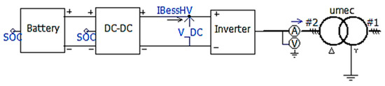
Figure 9.
Model of the ESS.
3.2. Modeling of PV
The model of the PV system consists of PV arrays, an inverter, and a transformer. Here, the PV arrays use a voltage source, and the inverter can independently control the active and reactive power using the Park transform and the PLL. The overall control topology is shown in Figure 10 [21].
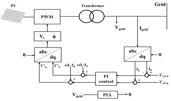
Figure 10.
Control topology of PV.
Using the Park transform, parameters such as voltage and current that change over time become constants, making it easy to design the controller, and control the active and reactive power independently of each other as shown in Equations (9) and (10).
where, P: active power, Q: reactive power, V0: inverter instantaneous voltage, Iref_q: q-axis reference current, Iref_d: d-axis reference current.
The three-phase voltage obtained by the PI controller and the inverse Park transform introduce Equations (11) and (12) to derive the six PWM (Pulse Width Modulation) signals. Figure 11 shows the six PWM signals to drive the IGBT (Insulated Gate Bipolar Transistor).
where, : phase angle of the linkage grid, Vt: voltage of the linkage grid, : q-axis reference voltage, : d-axis reference voltage.
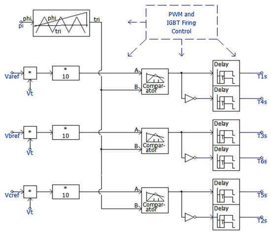
Figure 11.
PWM for the IGBT control.
Figure 12 shows the modeling of a grid-connected inverter. IGBT, driven by six PWM signals, converts the DC generated from the PV into a three-phase AC with a 120° phase difference and sends it to the grid.
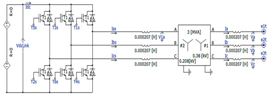
Figure 12.
Grid connected inverter.
3.3. Modeling of the Operation Algorithm of the ESS
In the LVDS, when the power consumption by the load and EV charger exceeds the transformer capacity, the ESS supplies the excess power, and when the amount of RES generation exceeds the transformer capacity, the ESS absorbs the excess power. The control algorithm is operated in accordance with Figure 7 to ensure that the feeder capacity and voltage do not exceed the allowable limit.
In the control algorithm, Figure 13 shows the modeling for determining the charging/discharging mode of the ESS. The signal alpha, which determines the ESS mode, depends on the sign of the sum of the power measured at each bus. That is, if the sum of the measured power is positive, the alpha becomes 1 and the ESS operates in discharging mode, and if it is negative, the alpha becomes 0 and the ESS is in charging mode. At this time, the sign of power assumes a positive direction into the load.
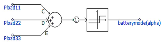
Figure 13.
Decision of a charging/discharging mode.
Figure 14 shows the model for determining the charge/discharge capacity of the ESS. The ESS does not operate immediately when the mode is determined, and operates only when the sum of the measured powers exceeds the reference values PL and PG considering the margin. That is, in the discharging mode, when the sum of the power consumed by the load and EV chargers exceeds the reference value PL, the discharging operation signal beta becomes 1 and the process proceeds to the next step. Similarly, in the charging mode, when the sum of the power of the PV exceeds the reference value PG, the charging operation signal (γ) becomes 1. In addition, the signal alpha is applied to control the mode not to operate at the same time.
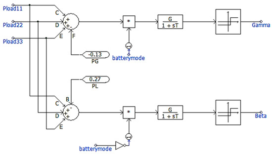
Figure 14.
Decision of a charging/discharging capacity of the ESS.
Once the mode and output power of the ESS are determined, the DC-DC converter receives the output power set value from the control algorithm and the ESS performs charging/discharging operation based on the set value in each mode. Figure 15 shows how the DC-DC converter receives the output power set value in each mode. That is, in the discharging mode, when the signal (β) is 1, the Pref-dischg derived from Equation (3) becomes the output command value, however, when the sum of the consumed power is less than the PL considering the margin, the signal (β) becomes 0 and the output command value is 0. Additionally, in the charging mode, when the signal (γ) is 1, the Pref-chg derived from Equation (5) becomes the output command value. When the sum of the generated power is less than the PG considering the margin, the signal (γ) becomes 0 and the output command value becomes 0.
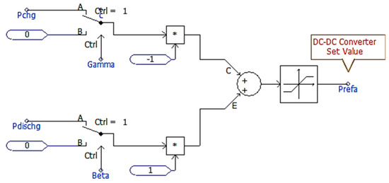
Figure 15.
ESS output power set-point to the DC-DC converter.
Figure 16 shows the high-level controller of a DC-DC converter. The SOC operating range and charging/discharging mode signal () of the ESS are used as buck/boost operation signals of the DC-DC converter. That is, when the ESS operates in the charging mode, the DC-DC converter operates as a buck converter, and when operating in the discharging mode, it operates as a boost converter.
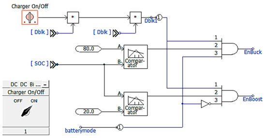
Figure 16.
Buck/boost converter operation.
4. Case Studies
4.1. Simulation Model
Based on the model of the LVDS in Figure 17, the system parameter and section data of the secondary feeder are assumed as Table 3. Pole transformer having the 100 kVA per phase is considered as 13,200 V/230 V. Additionally, a 95 mm2 CV cable with an impedance value of 0.248 ohm/km is used at the main feeder which is from directly under the pole transformer to the end section. In addition, a 185 CV cable with an impedance value of 0.129 ohm/km is used from the end section to the ESS in order to accept power capacity more than the main feeder.
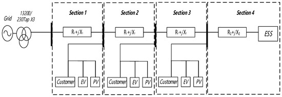
Figure 17.
LVDS model for the simulation.
Table 3.
Model parameters of the distribution system.
Additionally, other operation conditions for load, EV, the PV system, and ESS are summarized by:
- -
- The sum of power in all sections have a constraint condition that is assumed from 0 to 600 kW when the maximum demand time of the load and EV charging time proceed at the same time.
- -
- All PV systems are outputted from 0 to 600 kW per hour.
- -
- The ESS introduced at the end section is only operated when either the sum of each load or the sum of each PV generation power is exceeded over the reference value (PL, PG).
Figure 18 shows the PV output pattern during 24 hours assuming one second is one hour in the simulation. Additionally, PV output of individual customers are determined as 7 kW, and all PV systems are outputted from 0 to 600 kW per hour.
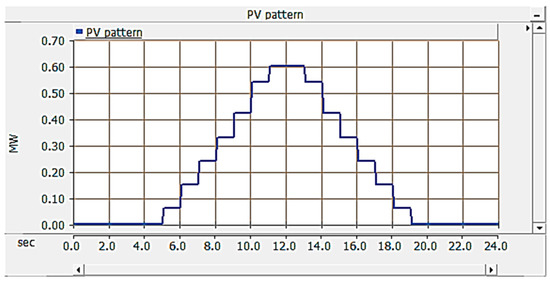
Figure 18.
PV output pattern.
On the other hand, Figure 19 shows the load pattern of the customer side considering the EV during the 24 hours assuming one second is one hour in the simulation. Additionally, this load pattern varies from 0 to 600 kW over time. The load pattern and PV pattern were used in the simulation analysis to solve the capacity expansion problems of electric vehicle and distributed energy in LVDS.
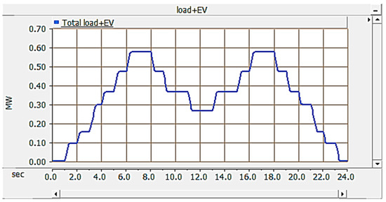
Figure 19.
Load + Electric Vehicle (EV) pattern.
4.2. Determination of the Reference Values (PL, PG)
The reference values, PL and PG, used for the charging/discharging operation of the ESS, are set in a state where the ESS is not connected, and the values are determined as the feeder power when the section voltage reaches the allowable limit according to [Step 1] in Section 2.3. According to the procedure, for PL, the load is gradually increased so that the voltage in section 3 reaches the lower limit (0.94 PU) as shown in Figure 20a. In Figure 20a–d, the x and the 0 represent the x-axis and y-axis, respectively. At this time, as shown in Figure 20b, the feeder power of section 1, which is the sum of the power consumption, becomes the reference value PL. In the case of PG, the PV generation is gradually increased so that the voltage in section 3 reaches the upper limit (1.06 PU) as shown in Figure 20c. At this time, as shown in Figure 20d, the feeder power of the section 1 in Figure 17, which is the sum of the generated powers, becomes the reference value PG. From the simulation results, the reference values PL and PG, which determine when to perform the charging and discharging operations of the ESS, are set to 280 and −50 kW considering the margin, respectively.
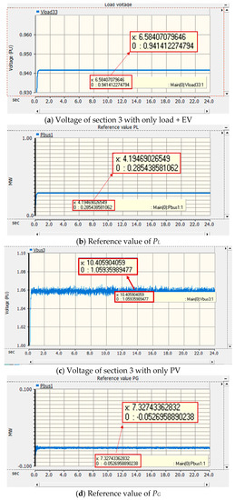
Figure 20.
Determination of PL and PG.
4.3. Power Characteristics of Distribution Systems with EV Chargers and an ESS
(1) Operation characteristics of LVDS with an EV charger
Figure 21a,b shows each sections’ voltage and power of the secondary feeder with an EV charger when an ESS is not operating. Through the simulation results in Figure 21a, it is confirmed that the end section voltage among the all section voltages could not be maintained to reasonable conditions (low voltage phenomena) when the EV are charged at all sections from 06:00–13:00 to 17:00–24:00. Additionally, Figure 21b shows that the maximum power of section 1 summed for all power is 570 kW, which is far beyond the rated capacity of the pole transformer (300 kW). Therefore, it can be emphasized that the section voltage and the feeder capacity cannot exactly be kept within the predefined allowable limit (voltage and capacity) when load and EV power are greater than capacity of the pole transformer.
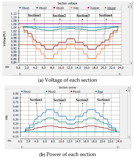
Figure 21.
Voltage and power of LVDS with EVCs when an ESS is not operating.
(2) Operation characteristics of the distribution system with an EV charger and ESS
Figure 22 shows each sections’ voltage and power in the secondary feeder with an EV charger when an ESS is introduced. From the simulation results in Figure 22a, it is confirmed that all section voltages could be maintained to reasonable conditions (low voltage phenomena) by the proposed ESS operation when the EV are charged at all sections from 06:00–13:00 to 17:00–24:00. Additionally, it is found that the power from section 1 to section 3 does not exceed the rated capacity of the feeder (300 kW) as shown in Figure 22b. Here, the negative value in Figure 22b means the reverse power flow. In other words, low voltage phenomena and exceeding capacity problems of the feeder were solved by ESS operation as shown in Figure 22. Therefore, it can be emphasized that the proposed algorithm can contributes to the section voltage and feeder capacity of LVDS.
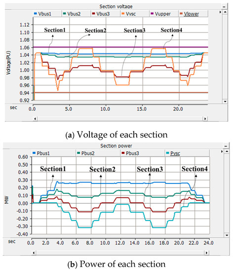
Figure 22.
Voltage and power of LVDS with EVCs when an ESS is operating.
4.4. Power Characteristic of Distribution Systems with EV Chargers, PV Systems, and ESS
(1) Operation characteristic of the distribution system with an EV charger and PV system
Figure 23 shows each sections’ voltage and power of the secondary feeder interconnected with an EV charger and PV system without considering of the ESS. From the simulation results in Figure 23a, it is confirmed that all section voltages could not be maintained to reasonable conditions (over voltage phenomena) when the PV systems are outputted to maximum power. Additionally, Figure 23b shows that the maximum power of section 1, summed for all power, is 570 kW, which is far beyond the rated capacity of the pole transformer (300 kW). Therefore, it can be emphasized that section voltage and feeder capacity cannot exactly be kept within the allowable limit (voltage and capacity) when PV generation is greater than the capacity of the pole transformer.
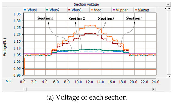
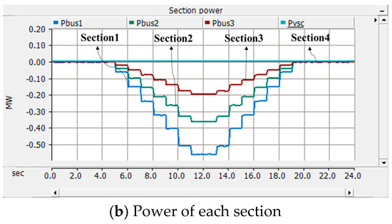
Figure 23.
Voltage and power of LVDS with a PV system when an ESS is not operating.
(2) Operation characteristic of the distribution system with an EV charger, PV system, and ESS
Figure 24 shows each sections’ voltages and power by the proposed operation strategy of ESS introduced in the secondary feeder with an EV charger and PV system. Based on the simulation results in Figure 24a, it is confirmed that the voltage of each section can be maintained to reasonable voltage range even when PV outputs at maximum. That is, when PV system outputs as a double capacity of pole transformer, it is found that the ESS can control the all voltages within an allowable limit. Additionally, it is clear that power from section 1 to the section 3 do not exceed the rated capacity of the pole transformer (300 kW) as shown in Figure 24b, except for the section 4 using cables with the capacity to accept more power. Therefore, it is confirmed that section voltage and feeder capacity could be kept exactly within the allowable limit (voltage and capacity) by the proposed operation algorithm of ESS when PV generation is greater than capacity of the pole transformer.
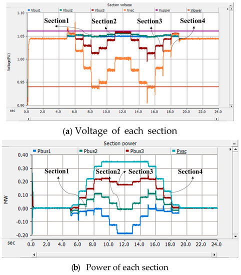
Figure 24.
Voltage and power of LVDS with a PV system when an ESS is operating.
4.5. Analysis of ESS Operation Characteristics
Figure 25 shows the SOC, active and reactive power characteristics of the ESS from Section 4.3. It can be seen that in discharging mode, the ESS supplies only active power and no reactive power to control the section voltage and power. Additionally, it is confirmed that SOC of the ESS could be operated within steady-state range in which is from 50% to 36% as shown in the below graph of Figure 25. Therefore, it is clear that the ESS operates efficiently according to the proposed algorithm.
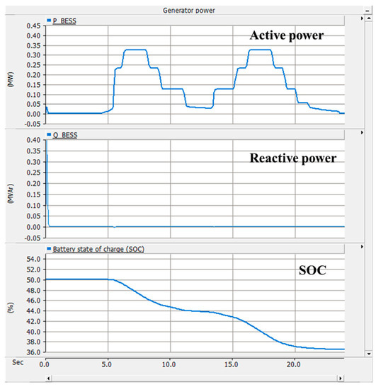
Figure 25.
Power and SOC characteristic of the ESS in discharging operation mode.
On the other hand, Figure 26 shows the SOC, active and reactive power characteristics of the ESS from Section 4.4. It can be seen that in charging mode, the active power of ESS controls the section voltage and power, and the reactive power is not used to control the ESS. Additionally, it is confirmed that SOC of ESS could be operated within steady-state range that is from 50% to 60% as shown below in Figure 26. Therefore, it is clear that ESS operates efficiently according to the proposed algorithm.
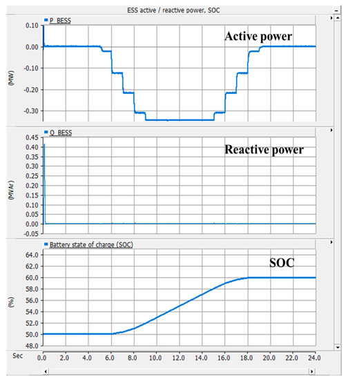
Figure 26.
Power and SOC characteristic of the ESS in charging operation mode.
5. Discussion
The power characteristic of the feeder can be evaluated by the degree of how close the power is maintained to the rated capacity in the secondary feeder. In this paper, the RMSE (Root Mean Square Error) was used as PI and was calculated according to Equation (13) using the pole transformer rated power and the feeder data that represent the most severe power characteristics. Therefore, a PI can be defined as a form of the squared differences between the rated capacity and demand power in secondary feeder as follows:
where, P1 is the data having the most severe power characteristics of in the secondary feeder, Prated is the reference capacity (300 kW) of the pole transformer, is the total data.
(1) ESS charging state
Figure 27 and Table 4 show the performance index by the introduction of the ESS in the secondary feeder with only an EV charger and customer load. From the result of the performance index based on Table 4, it was clear that the feeder capacity keeps better within the rated capacity boundary by the ESS charging operation.
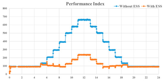
Figure 27.
Comparison of the performance index in charging mode.
Table 4.
Comparison of the performance index of each method.
(2) ESS discharging state
Figure 28 and Table 5 show the performance index by the introduction of the ESS in the secondary feeder with an EV charger, customer load, and PV system. From the result of the performance index based on Table 5, it was clear that the feeder capacity keeps better within the rated capacity boundary by the ESS discharging operation.
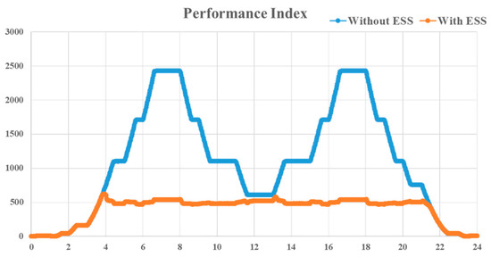
Figure 28.
Comparison of the performance index in discharging mode.
Table 5.
Comparison of the performance index of each method.
6. Conclusions
In this paper, an innovative operation algorithm was proposed that can maximize the acceptability of EV and RES and comply with system regulations by using bidirectional power flow of the ESS connected to the end side of LVDS. The main results are summarized as follows.
- (1)
- The innovative operation algorithm of the ESS was proposed to increase the capacity of EV and RES connected to the LVDS up to twice the capacity of pole transformer and to solve the voltage and feeder capacity problems that may occur at this time.
- (2)
- Modeling of a low voltage distribution system consisting of an ESS, PV, EV and load using PSCAD/EMTDC was presented. Additionally, through the simulation results, it was confirmed that the voltage and power of each section can be controlled to satisfy the allowable limit by discharging the ESS when the EV + load is twice the capacity of the pole transformer.
- (3)
- In addition, it was confirmed that the voltage and power of each section can be controlled to satisfy the allowable limit by charging mode of the ESS when the PV generation is twice the capacity of the pole transformer.
In this paper, the PV and the load with EV connected in each section were set to the same size, and the ability of the proposed method was assessed and discussed through simulation results. However, depending on the load distribution and power factor in the LVDS, the voltage profile may be different and the size of the ESS for stabilization may be different. Therefore, research will be conducted to improve the algorithm in consideration of load distribution and power factor and to prove it through hardware tests.
Author Contributions
All of the authors contributed to publishing this paper. K.-S.R. carried out modeling, simulations and compiled the manuscript. The literature review and simulation analysis were performed by D.-J.K., H.K., Y.-H.N., B.K. and H.-C.K., collected the data and investigated early works.
Funding
This research was funded by the Ministry of Trade, Industry and Energy, and supported by the Korea Institute of Energy Technology Evaluation and Planning (KETEP) grant number (No. 20172410100030). This work was conducted under the framework of Research and Development Program of the Korea Institute of Energy Research (KIER) (No. B9-2421). The APC was funded by (No.20172410100030).
Acknowledgments
This research was funded by the Ministry of Trade, Industry and Energy, and supported by the Korea Institute of Energy Technology Evaluation and Planning (KETEP) (No. 20172410100030). This work was conducted under the framework of Research and Development Program of the Korea Institute of Energy Research (KIER) (No. B9-2421).
Conflicts of Interest
The authors declare no conflict of interest.
Acronyms
The list of acronyms mentioned throughout the paper is as follows.
| ESS | Energy Storage System |
| EVC | Electric Vehicle Charger |
| EV | Electric Vehicle |
| LVDS | Low Voltage Distribution System |
| PI | Performance Index |
| PV | Photovoltaic |
| SOC | State Of Charge |
| RES | Renewable Energy Resource |
| RMSE | Root Mean Square Error |
References
- Park, M.S.; Barrett, M.; Cassarino, T.G. Assessment of future renewable energy scenarios in South Korea based on costs, emissions and weather-driven hourly simulation. Renew. Energy 2019, 143, 1388–1396. [Google Scholar] [CrossRef]
- Park, Y.C.; Kim, D.S.; Huh, J.C.; Kim, Y.G. New and Renewable Energy Policies of Jeju Island in Korea. In Proceedings of the World Renewable Energy Congress-Sweden, Linköping, Sweden, 8–13 May 2011; pp. 2446–2453. [Google Scholar]
- Lavrijssen, S.; Anna, M.; Ana, T. The Changing World of the DSO in a Smart Energy System Environment: Key Issues and Policy Recommendations; TILEC Discussion Paper No. 2018-015; Elsevier: Amsterdam, Nederland, 2016; pp. 1–98. [Google Scholar]
- Behzad, H.; Majid, S.; Payam, T. Stochastic-based optimal charging strategy for plug-in electric vehicles aggregator under incentive and regulatory policies of DSO. IEEE Trans. Veh. Technol. 2019, 68, 3234–3245. [Google Scholar]
- Reza, H.; Hedayat, S. Emergence of hybrid energy storage systems in renewable energy and transport applications—A review. Renew. Sustain. Energy Rev. 2016, 65, 11–23. [Google Scholar]
- Matiha, Z.; Pavlos, S.; Niko, D.H.; Tomislav, C.; Davor, S. Review of energy storage allocation in power distribution networks: Applications, methods and future research. IET Gener. Transm. Distrib. 2016, 10, 645–652. [Google Scholar]
- Ko, Y.S. A study on the application cases analysis of ESS (Energy Storage System) to electric power system. J. KIECS 2016, 11, 53–58. [Google Scholar]
- Shim, J.W.; Cho, Y.; Kim, S.; Min, S.W.; Hur, K. Synergistic control of SMES and battery energy storage for enabling dispatchability of renewable energy sources. IEEE Trans. Appl. Supercond. 2013, 23, 5701205. [Google Scholar] [CrossRef]
- Wang, Y.; Tan, K.T.; Peng, X.Y.; So, P.L. Coordinated control of distributed energy-storage systems for voltage regulation in distribution networks. IEEE Trans. Power Deliv. 2016, 31, 1132–1141. [Google Scholar] [CrossRef]
- Marra, F.; Yang, G.; Træholt, C.; Østergaard, J.; Larsen, E.A. Decentralized Storage Strategy for Residential Feeders with Photovoltaics. IEEE Trans. Smart Grid 2014, 5, 974–981. [Google Scholar] [CrossRef]
- Erdinc, O.; Tascikaraoglu, A.; Paterakis, N.G.; Dursun, I.; Sinim, M.C.J.; Catalão, P.S. Optimal sizing and siting of distributed generation and EV charging stations in distribution systems. In Proceedings of the IEEE PES ISGT-Europe, Torino, Italy, 26–29 September 2017; pp. 1–6. [Google Scholar]
- Chaudhari, K.; Ukil, A.; Kumar, K.N.; Manandhar, U.; Kollimalla, S.K. Hybrid optimization for economic deployment of ESS in PV-integrated EV charging stations. IEEE Trans. Ind. Inform. 2018, 14, 106–116. [Google Scholar] [CrossRef]
- Rho, D.S.; Kook, K.S.; Wang, Y.P. Optimal algorithms for voltage management in distribution systems interconnected with new dispersed sources. J. Electr. Eng. Technol. 2011, 6, 192–201. [Google Scholar] [CrossRef]
- Kim, B.K.; Nam, Y.H.; Ko, H.S.; Park, C.H.; Kim, H.C.; Ryu, K.S.; Kim, D.J. Novel voltage control method of the primary feeder by the energy storage system and step voltage regulator. Energies 2019, 12, 3357. [Google Scholar] [CrossRef]
- Falvo, M.C.; Grasselli, U.; Manganelli, M.A. Modesto. Small scale ESS for LV prosumers: An economic feasibility and sensitivity analysis. In Proceedings of the IEEE 15th International Conference on Environment and Electrical Engineering (EEEIC), Rome, Italy, 10–13 June 2015; pp. 950–955. [Google Scholar]
- Muyeen, S.M.; Ali, M.H.; Takahashi, R.; Murata, T.; Tamura, J. Wind generator output power smoothing and terminal voltage regulation by using STATCOM/ESS. In Proceedings of the IEEE Lausanne Power Tech, Lausanne, Switzerland, 1–5 July 2007; pp. 1232–1237. [Google Scholar]
- Elham, S.; Shahram, J. Cost reduction and peak shaving through domestic load shifting and DERs. Energy 2017, 124, 146–159. [Google Scholar]
- Mamandur, K.R.C.; Chenoweth, R.D. Optimal control of reactive power flow for improvements in voltage profiles and for real power loss minimization. IEEE Trans. Power Appar. Syst. 1981, 100, 3185–3194. [Google Scholar] [CrossRef]
- PSCAD/EMTDC. Three-Phase Battery Energy Storage System, Reversion 1; Powered by Manitoba Hydro. International Ltd.: Winnipeg, MB, USA; Available online: https://hvdc.ca/engineering/ (accessed on 29 August 2019).
- Tremblay, O.; Dessaint, L.A.; Dekkiche, A.I. A generic battery model for the dynamic simulation of hybrid electric vehicles. In Proceedings of the IEEE Vehicle Power and Propulsion Conference, Arlington, TX, USA, 9–12 September 2007; pp. 284–289. [Google Scholar]
- Kim, B.K.; Ryu, K.S.; Kim, C.H.; Rho, D.S. A study on the customer voltage characteristic of distribution system with large scale PV. Trans. Korean Inst. Electr. Eng. 2013, 62, 29–36. [Google Scholar] [CrossRef]


© 2019 by the authors. Licensee MDPI, Basel, Switzerland. This article is an open access article distributed under the terms and conditions of the Creative Commons Attribution (CC BY) license (http://creativecommons.org/licenses/by/4.0/).