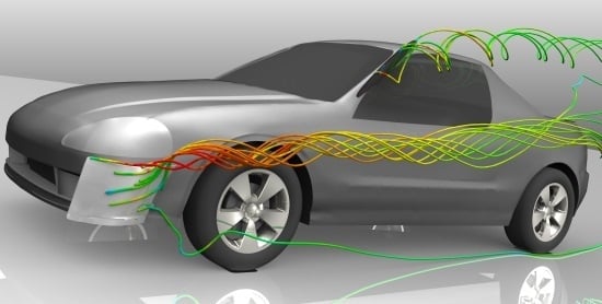
Influence of Side Spoilers on the Aerodynamic Properties of a Sports Car
Abstract
:1. Introduction
2. Materials and Methods
3. Results and Discussion
3.1. The Side Spoiler on a Quarter Glass
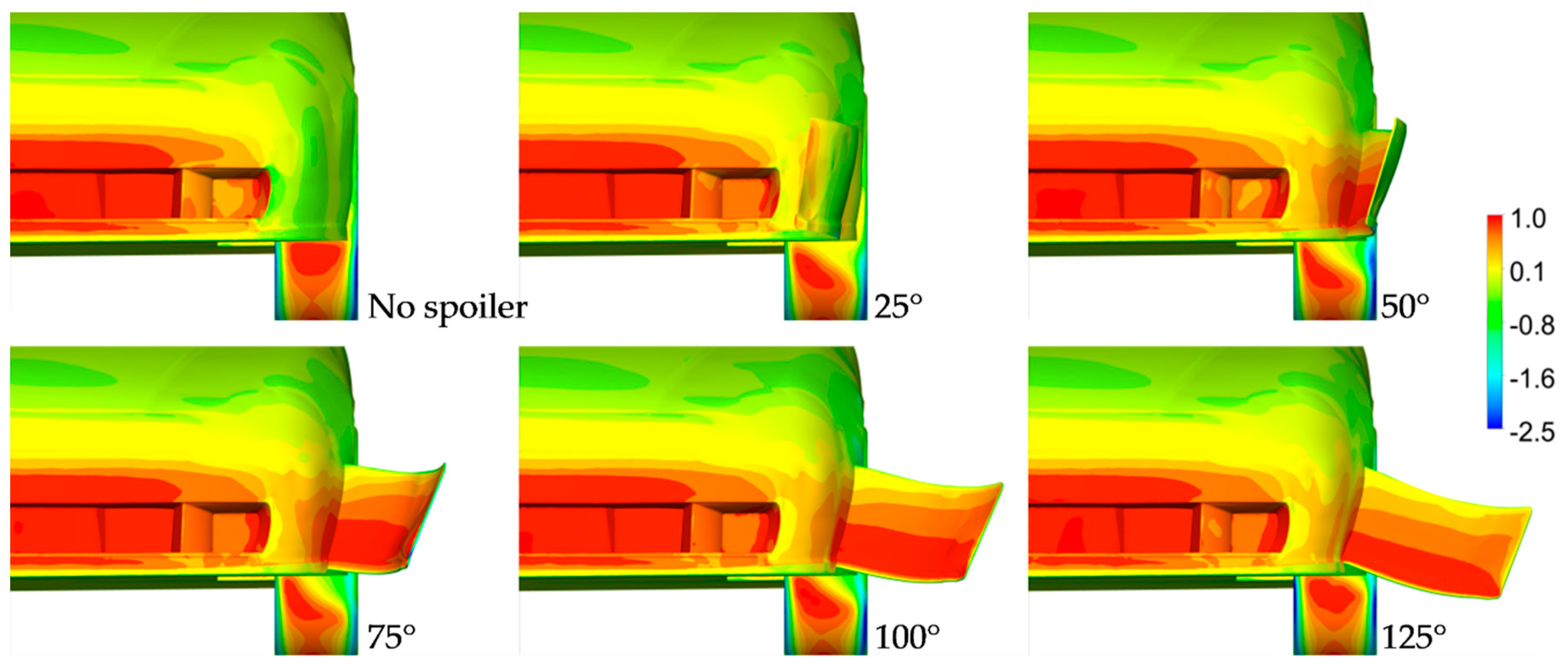
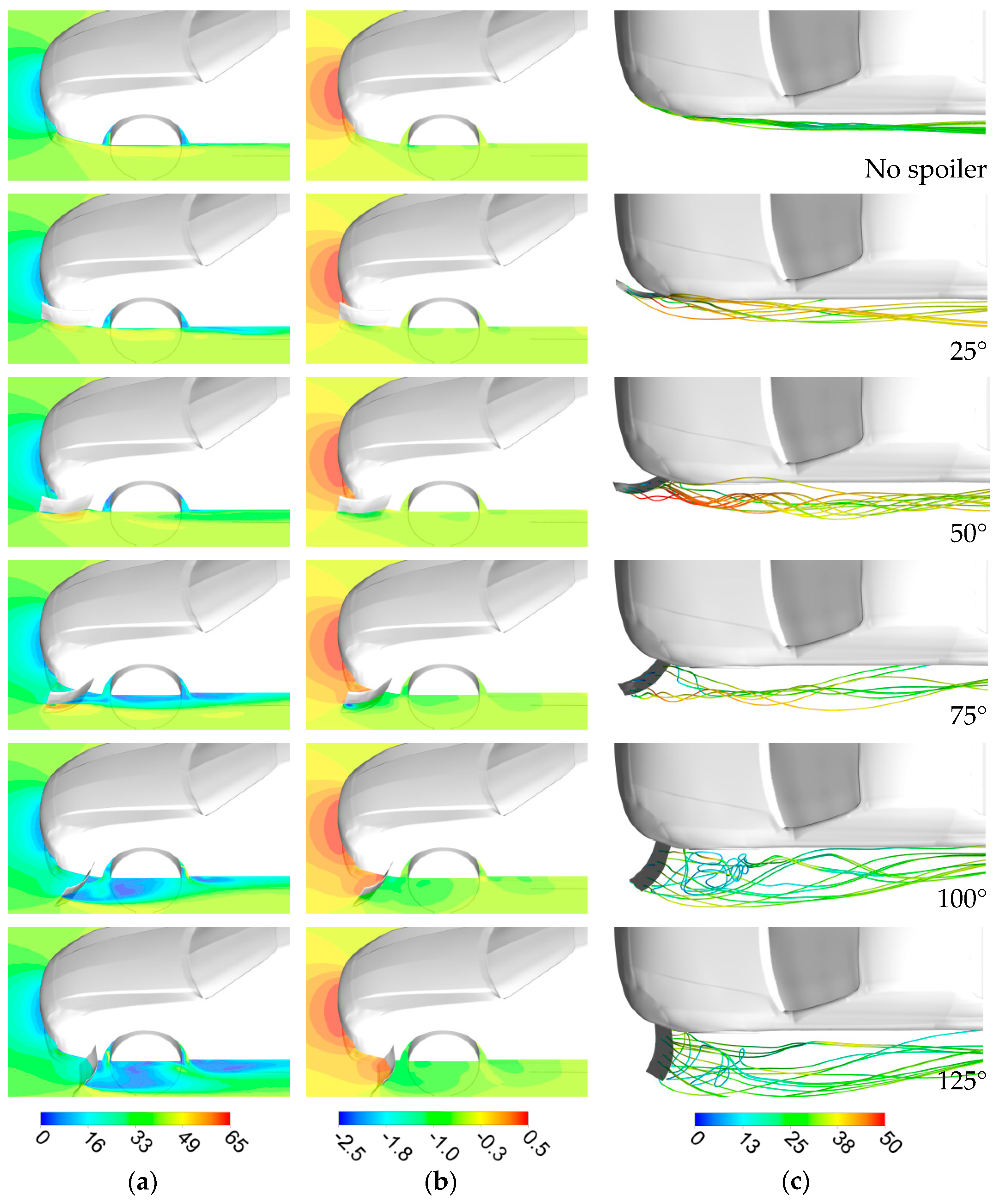
3.2. The Side Spoiler on a Front Bumper
3.3. Cases Chosen for Different Yaw Conditions
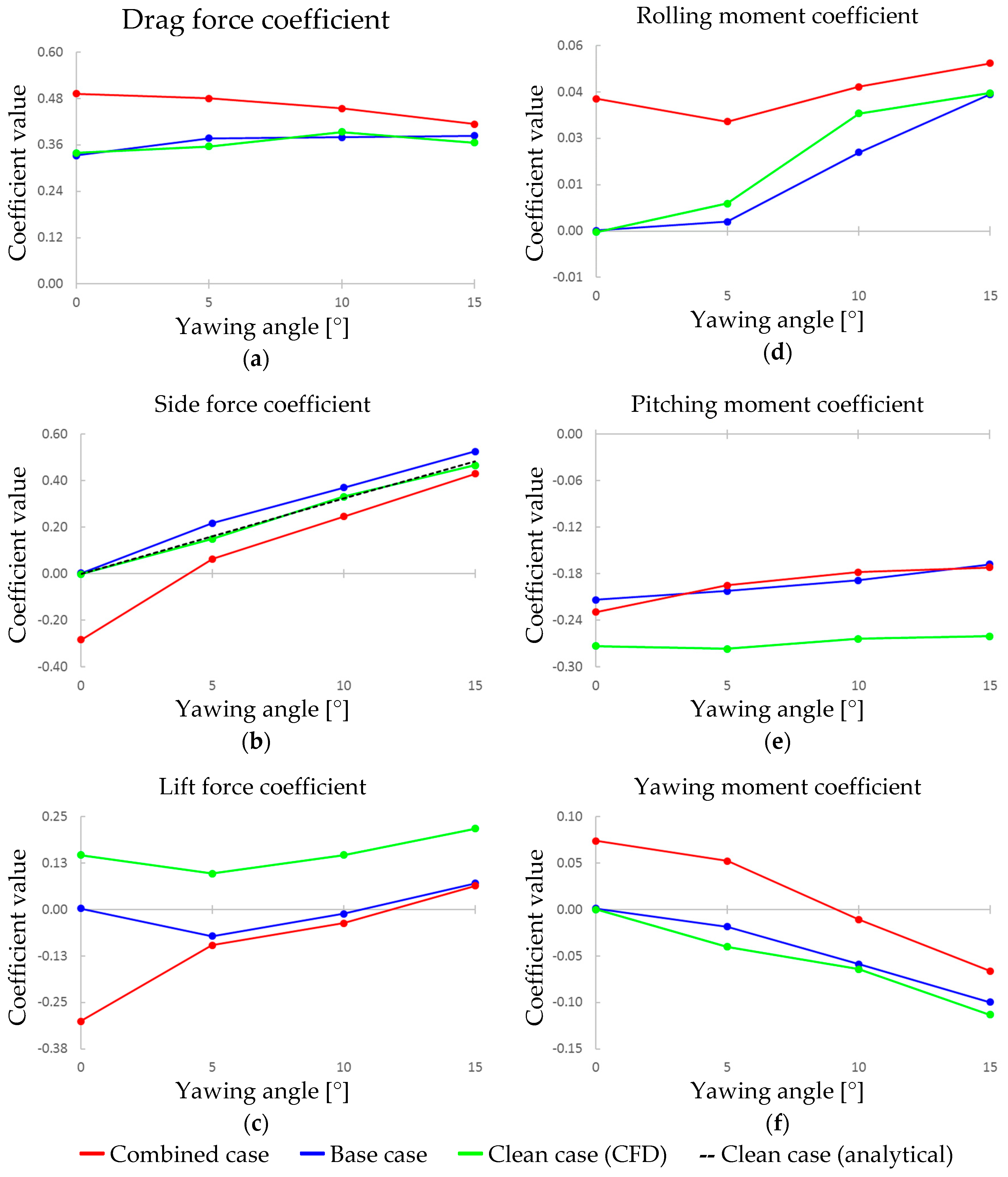
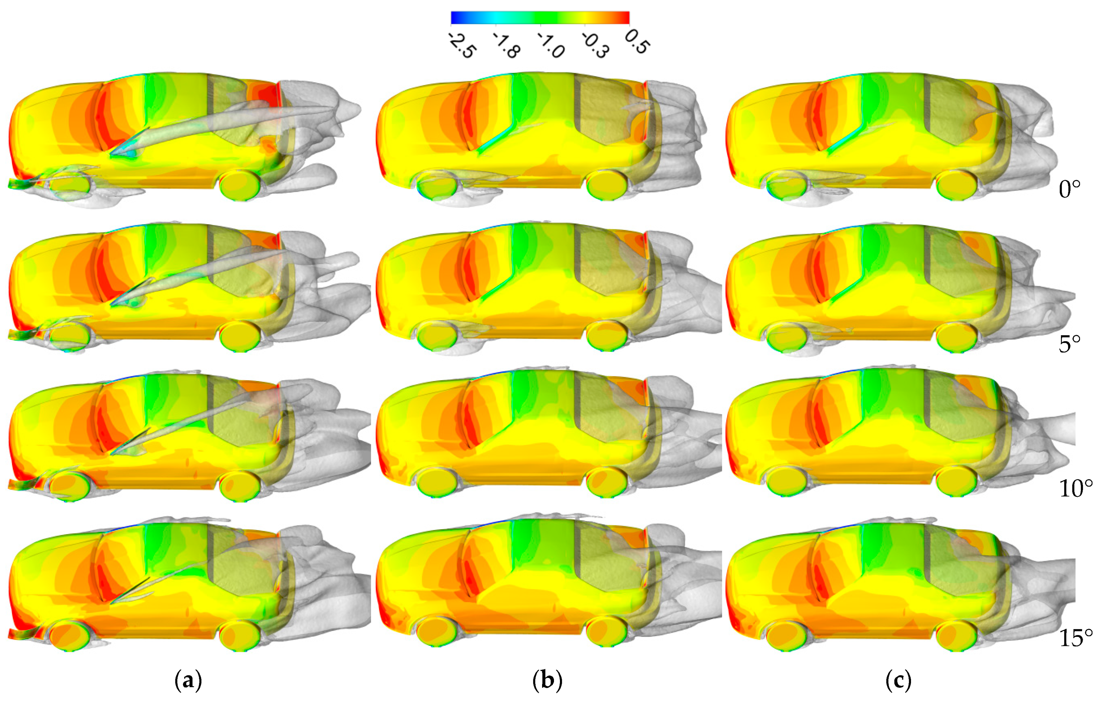
3.4. Results at Different Yaw Angles
4. Conclusions
Author Contributions
Funding
Conflicts of Interest
Abbreviations
| CFD | Computational Fluid Dynamics |
| NASCAR | National Association for Stock Car Auto Racing |
| RANS | Reynolds-Averaged Navier Stokes |
| SST | Shear Stress Transport |
Appendix A. The Main Dimensions of the Spoilers and the Car Body

Appendix B. Tables with the Values Used in Each Graph
| Angle [°] | Cx | Cy | Cz | Cmx | Cmy | Cmz | ||||||
|---|---|---|---|---|---|---|---|---|---|---|---|---|
| Spoiler | Total | Spoiler | Total | Spoiler | Total | Spoiler | Total | Spoiler | Total | Spoiler | Total | |
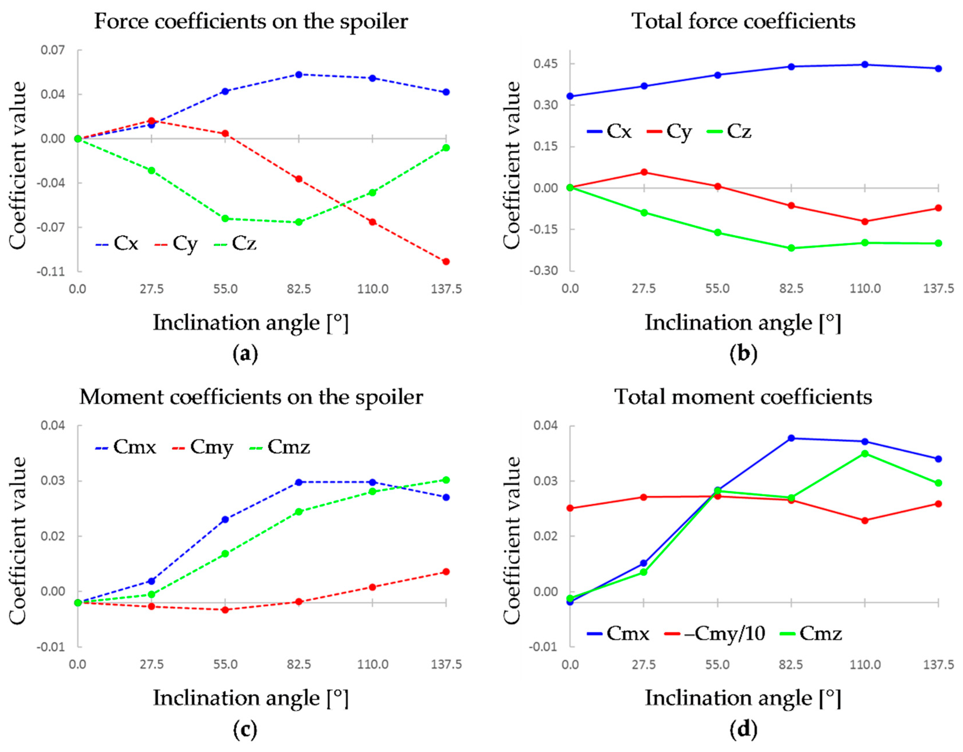
| 0.0 | – | 0.333 | – | 0.002 | – | 0.002 | 0.000 | 0.000 | 0.000 | –0.214 | 0.000 | 0.001 |
| 27.5 | 0.011 | 0.370 | 0.014 | 0.058 | –0.025 | –0.088 | 0.005 | 0.009 | –0.001 | –0.239 | 0.002 | 0.007 |
| 55.0 | 0.038 | 0.410 | 0.004 | 0.007 | –0.063 | –0.160 | 0.019 | 0.025 | –0.002 | –0.241 | 0.011 | 0.025 |
| 82.5 | 0.051 | 0.440 | –0.032 | –0.063 | –0.066 | –0.218 | 0.027 | 0.037 | 0.000 | –0.232 | 0.021 | 0.024 |
| 110.0 | 0.048 | 0.448 | –0.066 | –0.121 | –0.042 | –0.198 | 0.027 | 0.036 | 0.004 | –0.186 | 0.025 | 0.034 |
| 137.5 | 0.037 | 0.433 | –0.097 | –0.072 | –0.007 | –0.200 | 0.024 | 0.033 | 0.007 | –0.224 | 0.028 | 0.027 |
| Angle [°] | Cx | Cy | Cz | Cmx | Cmy | Cmz | ||||||
|---|---|---|---|---|---|---|---|---|---|---|---|---|
| Spoiler | Total | Spoiler | Total | Spoiler | Total | Spoiler | Total | Spoiler | Total | Spoiler | Total | |
| 0 | – | 0.333 | – | 0.002 | – | 0.002 | 0.000 | 0.000 | 0.000 | –0.214 | 0.000 | 0.001 |
| 25.0 | –0.007 | 0.346 | –0.046 | –0.061 | –0.008 | –0.084 | 0.000 | 0.000 | –0.006 | –0.247 | 0.032 | 0.020 |
| 50.0 | 0.012 | 0.368 | –0.081 | –0.030 | –0.025 | –0.065 | 0.004 | 0.016 | –0.020 | –0.230 | 0.067 | 0.053 |
| 75.0 | 0.045 | 0.403 | –0.084 | –0.135 | –0.044 | –0.179 | 0.011 | 0.021 | –0.037 | –0.284 | 0.081 | 0.074 |
| 100.0 | 0.065 | 0.404 | –0.039 | –0.109 | –0.046 | –0.166 | 0.016 | 0.023 | –0.039 | –0.282 | 0.055 | 0.077 |
| 125.0 | 0.075 | 0.415 | –0.003 | –0.103 | –0.050 | –0.193 | 0.020 | 0.029 | –0.042 | –0.281 | 0.033 | 0.059 |
| Combined case | Base case | ||||||||||||
| Yaw [°] | Cx | Cy | Cz | Cmx | Cmy | Cmz | Yaw [°] | Cx | Cy | Cz | Cmx | Cmy | Cmz |
| 0 | 0.492 | –0.285 | –0.301 | 0.040 | –0.230 | 0.074 | 0 | 0.333 | 0.002 | 0.002 | 0.000 | –0.214 | 0.001 |
| 5 | 0.480 | 0.064 | –0.096 | 0.033 | –0.195 | 0.052 | 5 | 0.377 | 0.218 | –0.072 | 0.003 | –0.202 | –0.019 |
| 10 | 0.454 | 0.246 | –0.037 | 0.044 | –0.178 | –0.011 | 10 | 0.379 | 0.371 | –0.012 | 0.024 | –0.189 | –0.059 |
| 15 | 0.414 | 0.430 | 0.063 | 0.051 | –0.172 | –0.066 | 15 | 0.383 | 0.527 | 0.071 | 0.041 | –0.168 | –0.100 |
| Clean case (CFD) | Clean case (analytical) | ||||||||||||
| Yaw [°] | Cx | Cy | Cz | Cmx | Cmy | Cmz | Yaw [°] | Cx | Cy | Cz | Cmx | Cmy | Cmz |
| 0 | 0.339 | –0.001 | 0.147 | 0.000 | –0.273 | 0.000 | 0 | – | 0.000 | – | – | – | – |
| 5 | 0.356 | 0.150 | 0.096 | 0.008 | –0.277 | –0.040 | 5 | – | 0.161 | – | – | – | – |
| 10 | 0.394 | 0.331 | 0.147 | 0.035 | –0.264 | –0.064 | 10 | – | 0.323 | – | – | – | – |
| 15 | 0.366 | 0.467 | 0.218 | 0.042 | –0.261 | –0.113 | 15 | – | 0.484 | – | – | – | – |
References
- Howell, J.P. The side load distribution on a Rover 800 saloon car under crosswind conditions. J. Wind Eng. Ind. Aerodyn. 1996, 60, 139–153. [Google Scholar] [CrossRef]
- Carlino, G.; Cardano, D.; Cogotti, A. A New Technique to Measure the Aerodynamic Response of Passenger Cars by a Continuous Flow Yawing; SAE Technical Paper 2007-01-0902; SAE: Warrendale, PA, USA, 2007. [Google Scholar]
- Pfeiffer, J.; King, R. Robust control of drag and lateral dynamic response for road vehicles exposed to cross-Wind gusts. Exp. Fluids 2018, 59, 45. [Google Scholar] [CrossRef] [Green Version]
- Volpe, R.; Ferrand, V.; Da Silva, A.; Le Moyne, L. Forces and flow structures evolution on a car body in a sudden crosswind. J. Wind Eng. Ind. Aerodyn. 2014, 128, 114–125. [Google Scholar] [CrossRef] [Green Version]
- Kee, J.D.; Rho, J.H.; Kim, K.H.; Lee, D.H. High speed driving stability of passenger car under crosswind effects. Int. J. Automot. Technol. 2014, 15, 741–747. [Google Scholar] [CrossRef]
- D’Hooge, A.; Rebbeck, L.; Palin, R.; Murphy, Q.; Gargoloff, J.; Duncan, B. Application of Real-World Wind Conditions for Assessing Aerodynamic Drag for On-Road Range Prediction; SAE Technical Paper 2015-01-1551; SAE: Warrendale, PA, USA, 2015. [Google Scholar]
- Howell, J.; Forbes, D.; Passmore, M.; Page, G. The Effect of a Sheared Crosswind Flow on Car Aerodynamics. SAE Int. J. Passeng. Cars Mech. Syst. 2017, 10, 278–285. [Google Scholar] [CrossRef]
- Lewington, N.; Ohra-Aho, L.; Lange, O.; Rudnik, K. The Application of a One-Way Coupled Aerodynamic and Multi-Body Dynamics Simulation Process to Predict Vehicle Response during a Severe Crosswind Event; SAE Technical Paper 2017-01-1515; SAE: Warrendale, PA, USA, 2017. [Google Scholar]
- Forbes, D.C.; Page, G.J.; Passmore, M.A.; Gaylard, A.P. A Fully Coupled, 6 Degree-of-Freedom, Aerodynamic and Vehicle Handling Crosswind Simulation using the DrivAer Model. SAE Int. J. Passeng. Cars Mech. Syst. 2016, 9. [Google Scholar] [CrossRef] [Green Version]
- Huang, T.; Gu, Z.; Feng, C.; Zeng, W. Transient aerodynamics simulations of a road vehicle in the crosswind condition coupled with the vehicle’s motion. Proc. Inst. Mech. Eng. Part D J. Automob. Eng. 2018, 232, 583–598. [Google Scholar] [CrossRef]
- Okada, Y.; Nouzawa, T.; Okamoto, S.; Fujita, T.; Kamioka, T.; Tsubokura, M. Unsteady Vehicle Aerodynamics during a Dynamic Steering Action: 1st Report, On-Road Analysis; SAE Technical Paper 2012-01-0446; SAE: Warrendale, PA, USA, 2012. [Google Scholar]
- Tsubokura, M.; Ikawa, Y.; Nakashima, T.; Okada, Y.; Kamioka, T.; Nouzawa, T. Unsteady Vehicle Aerodynamics during a Dynamic Steering Action: 2nd Report, Numerical Analysis. SAE Int. J. Passeng. Cars Mech. Syst. 2012, 5, 340–357. [Google Scholar] [CrossRef]
- Windsor, S. Real world drag coefficient is it wind averaged drag? In Proceedings of the The International Vehicle Aerodynamics; Woodhead Publishing: Sawston\London, UK, 2014. [Google Scholar]
- Howell, J. Aerodynamic Drag of Passenger Cars at Yaw. SAE Int. J. Passeng. Cars Mech. Syst. 2015, 8, 306–316. [Google Scholar] [CrossRef]
- Iinuma, Y.; Taniguchi, K.; Oshima, M. Aerodynamics Development for a New EV Hatchback Considering Crosswind Sensitivity; SAE Technical Paper 2018-01-0715; SAE: Warrendale, PA, USA, 2018. [Google Scholar]
- Fu, C.; Bounds, C.P.; Selent, C.; Uddin, M. Turbulence modeling effects on the aerodynamic characterizations of a NASCAR Generation 6 racecar subject to yaw and pitch changes. Proc. Inst. Mech. Eng. Part D J. Automob. Eng. 2019, 233, 095440701982647. [Google Scholar] [CrossRef]
- Jacuzzi, E.; Barrier, A.; Granlund, K.O. NASCAR Race Vehicle Wake Modification via Passive Blown Ducts and its Effect on Trailing Vehicle Drag. In Proceedings of the 2018 AIAA Aerospace Sciences Meeting, Kissimmee, FL, USA, 8–12 January 2018; American Institute of Aeronautics and Astronautics: Reston, VA, USA, 2018. [Google Scholar]
- Jacuzzi, E.; Aleman Chona, M.; Granlund, K.O. Improvements in NASCAR Race Vehicle Side Force and Yawing Moment Stability in Race Conditions Using Active or Passive Blowing. In Proceedings of the AIAA Scitech 2019 Forum, San Diego, CA, USA, 7–11 January; American Institute of Aeronautics and Astronautics: Reston, VA, USA, 2019. [Google Scholar]
- Fu, C.; Uddin, M.; Robinson, A.C. Turbulence modeling effects on the CFD predictions of flow over a NASCAR Gen 6 racecar. J. Wind Eng. Ind. Aerodyn. 2018, 176, 98–111. [Google Scholar] [CrossRef]
- Jacuzzi, E.; Granlund, K. Passive flow control for drag reduction in vehicle platoons. J. Wind Eng. Ind. Aerodyn. 2019, 189, 104–117. [Google Scholar] [CrossRef]
- Nelson, G.; Roush, J.; Eaker, G.; Wallis, S. The Development and Manufacture of a Roof Mounted Aero Flap System for Race Car Applications; SAE Technical Paper 942522; SAE: Warrendale, PA, USA, 1994. [Google Scholar]
- Johansson, M.O.; Katz, J. Lateral Aerodynamics of a Generic Sprint Car Configuration; SAE Technical Paper 2002-01-331; SAE: Warrendale, PA, USA, 2002; pp. 2331–2338. [Google Scholar]
- Willumeit, H.P.; Muller, K.; Dodlbacher, G.; Matheis, A. Method To Correlate Vehicular Behaviour and Driver’S Judgement Under Side Wind Disturbances. Veh. Syst. Dyn. 1988, 17, 508–524. [Google Scholar] [CrossRef]
- Howell, J.; Panigrahi, S. Aerodynamic Side Forces on Passenger Cars at Yaw; SAE Technical Paper 2016-01-1620; SAE: Warrendale, PA, USA, 2016. [Google Scholar]
- Nakasato, K.; Tsubokura, M.; Ikeda, J.; Onishi, K.; Ota, S.; Takase, H.; Akasaka, K.; Ihara, H.; Oshima, M.; Araki, T. Coupled 6DoF Motion and Aerodynamic Crosswind Simulation Incorporating Driver Model. SAE Int. J. Passeng. Cars Mech. Syst. 2017, 10, 662–670. [Google Scholar] [CrossRef]
- Okumura, K.; Kuriyama, T.; Kato, A.; Hayashi, Y. Development of crosswind spoiler. JSAE Rev. 1996, 17, 293–299. [Google Scholar] [CrossRef]
- Sumitani, K.; Yamada, M. Development of “Aero Slit” Improvement of Aerodynamic Yaw Characteristics for Commercial Vehicles; SAE Technical Paper 890372; SAE: Warrendale, PA, USA, 1989. [Google Scholar]
- Kumar, A.; Sebben, S.; Sallstrom, E.; Jacobson, B.J.H.; Broniewicz, A.; Kumar, A.; Sebben, S.; Sallstrom, E.J.H.; Jacobson, B.; Broniewicz, A. Analysis of Subjective Qualitative Judgement of Passenger Vehicle High Speed Drivability due to Aerodynamics. Energies 2019, 12, 2839. [Google Scholar] [CrossRef] [Green Version]
- Kataoka, T.; China, H.; Nakagawa, K.; Yanagimoto, K.; Yoshida, M. Numerical Simulation of Road Vehicle Aerodynamics and Effect of Aerodynamic Devices. SAE Trans. 1991, 100, 722–734. [Google Scholar]
- Katz, J. Automotive Aerodynamics; Wiley: Hoboken, NJ, USA, 2016; ISBN 1119185726. [Google Scholar]
- Kurec, K.; Remer, M.; Mayer, T.; Tudruj, S.; Piechna, J. Flow control for a car-Mounted rear wing. Int. J. Mech. Sci. 2019, 152, 384–399. [Google Scholar] [CrossRef]
- Kurec, K.; Remer, M.; Broniszewski, J.; Bibik, P.; Tudruj, S.; Piechna, J. Advanced Modeling and Simulation of Vehicle Active Aerodynamic Safety. J. Adv. Transp. 2019, 2019, 7308590. [Google Scholar] [CrossRef] [Green Version]
- Broniszewski, J.; Piechna, J. A fully coupled analysis of unsteady aerodynamics impact on vehicle dynamics during braking. Eng. Appl. Comput. Fluid Mech. 2019, 13, 623–641. [Google Scholar] [CrossRef]
- Kurec, K.; Remer, M.; Piechna, J. The influence of different aerodynamic setups on enhancing a sports car’s braking. Int. J. Mech. Sci. 2019, 164, 105140. [Google Scholar] [CrossRef]
- Theory Guide; ANSYS® Academic Associate CFD, Release 16.2, Help System; ANSYS, Inc.: Canonsburg, PA, USA, 2016.
- Heft, A.I.; Indinger, T.; Adams, N.A. Introduction of a New Realistic Generic Car Model for Aerodynamic Investigations; SAE Technical Paper 2012-01-0168; SAE: Warrendale, PA, USA, 2012. [Google Scholar]
- Meshing User’s Guide; ANSYS® Academic Associate CFD, Release 16.2, Help System; ANSYS, Inc.: Canonsburg, PA, USA, 2016.
- Menter, F.R. Two-Equation eddy-Viscosity turbulence models for engineering applications. AIAA J. 1994, 32, 1598–1605. [Google Scholar] [CrossRef] [Green Version]
- Howell, J.; Baden Fuller, J. A Relationship between Lift and Lateral Aerodynamic Characteristics for Passenger Cars; SAE Technical Paper 2010-01-1025; SAE: Warrendale, PA, USA, 2010. [Google Scholar]
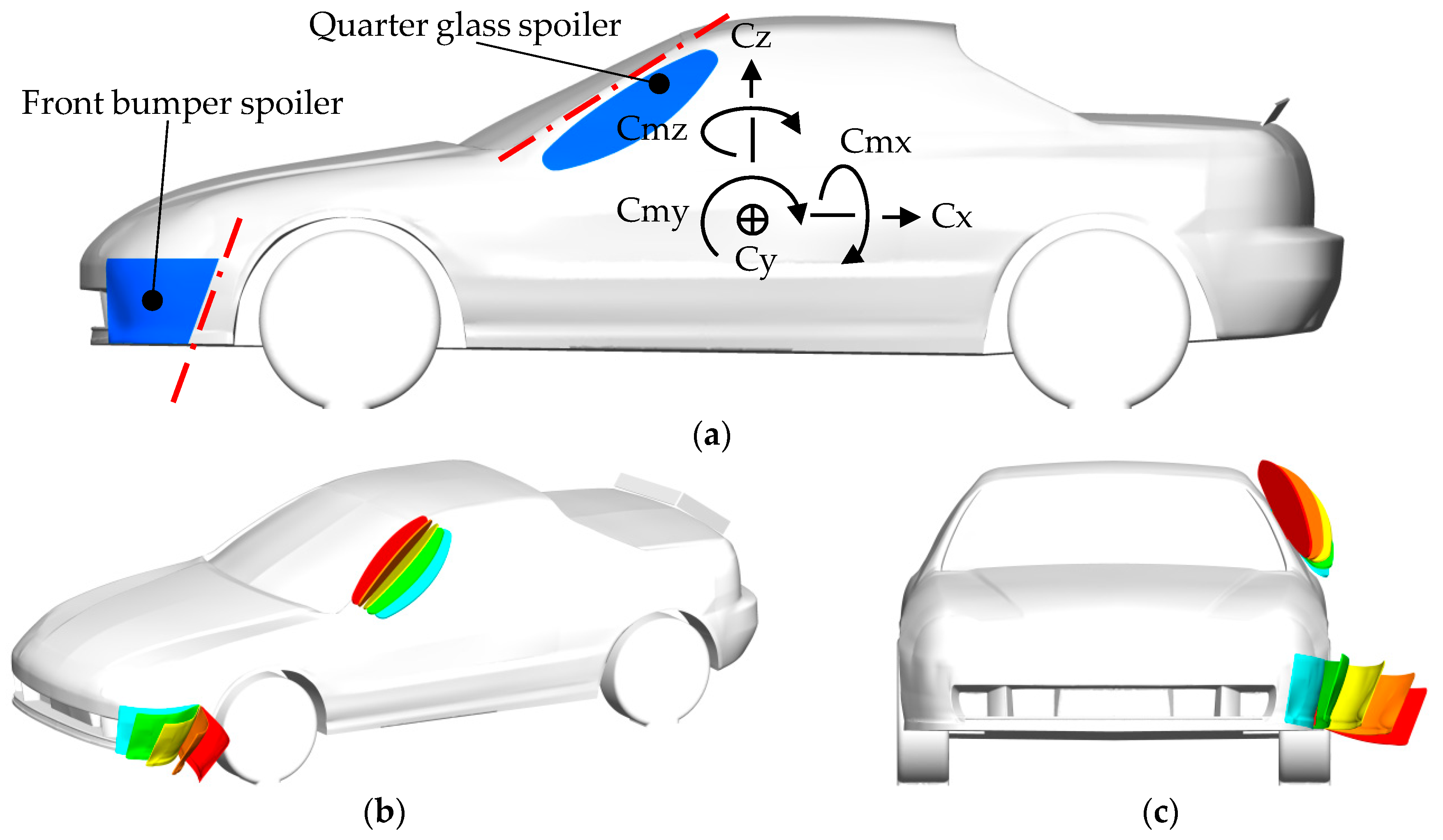
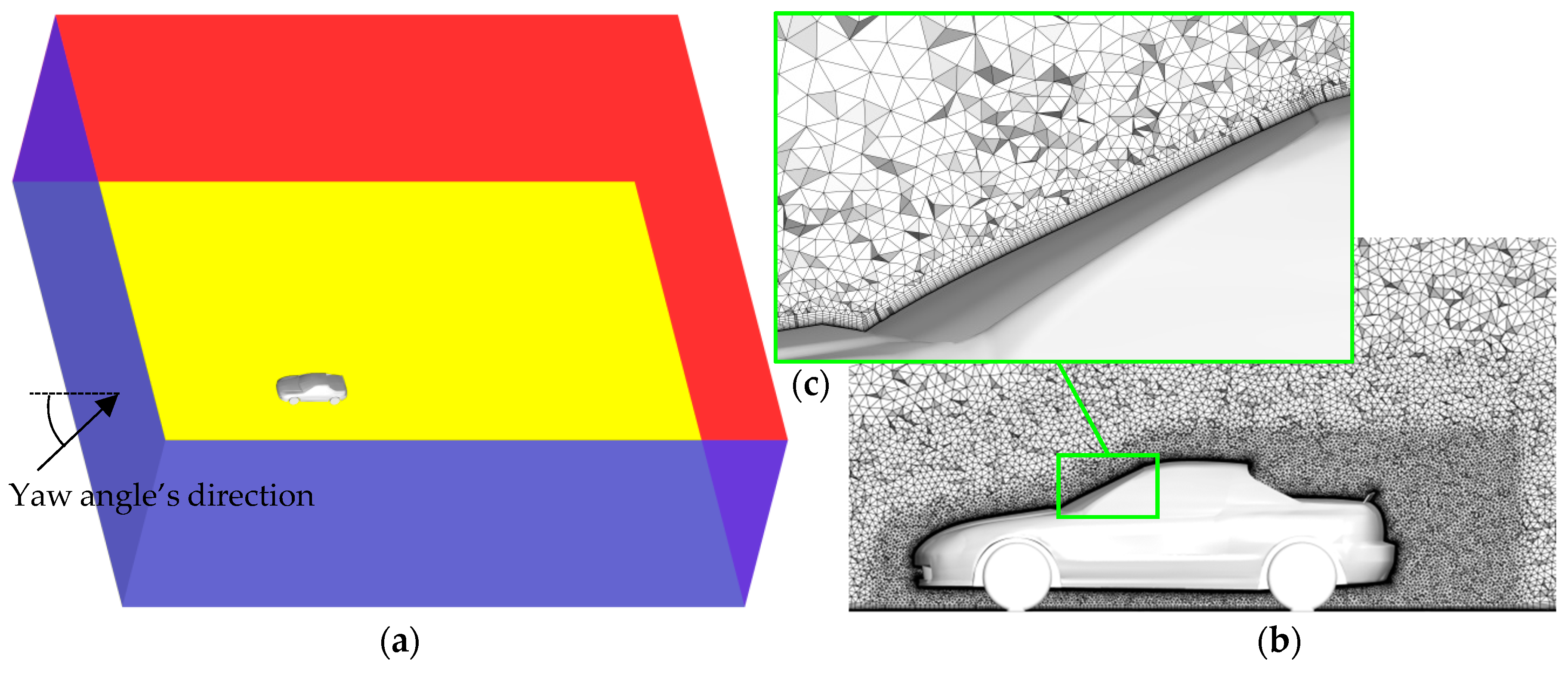
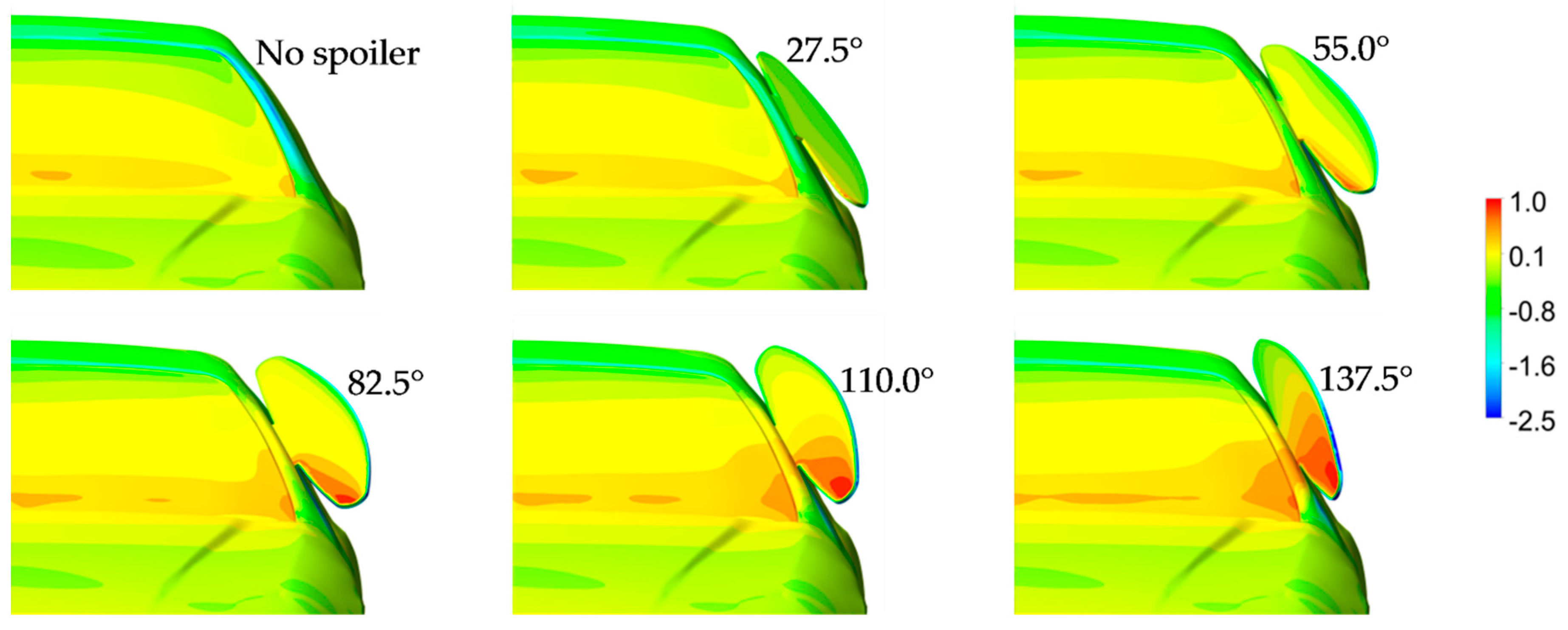



| Number of Cells | Drag Coefficient | Side Coefficient | Lift Coefficient |
|---|---|---|---|
| 2.187 × 10⁷ | 0.364 | 0.509 | 0.056 |
| 3.269 × 10⁷ | 0.383 | 0.527 | 0.071 |
| 4.395 × 10⁷ | 0.384 | 0.533 | 0.071 |
| Case. | Drag Coefficient | Side Coefficient | Lift Coefficient | Lift Distribution | Moment Coefficients | ||||||
|---|---|---|---|---|---|---|---|---|---|---|---|
| Spoiler | Total | Spoiler | Total | Spoiler | Total | Front | Rear | Cmx | Cmy | Cmz | |
| Clean | – | 0.339 | – | –0.001 | – | 0.147 | –0.125 | 0.272 | 0.000 | –0.273 | 0.000 |
| Base | – | 0.333 | – | 0.002 | – | 0.002 | –0.141 | 0.143 | 0.000 | –0.214 | 0.001 |
| Fr. bumper | 0.012 | 0.368 | –0.081 | –0.028 | –0.025 | –0.074 | –0.185 | 0.111 | 0.016 | –0.226 | 0.053 |
| Qtr. glass | 0.048 | 0.451 | –0.066 | –0.120 | –0.042 | –0.196 | –0.188 | –0.008 | 0.035 | –0.185 | 0.033 |
| Combined | 0.061 | 0.492 | –0.152 | –0.285 | –0.069 | –0.301 | –0.278 | –0.023 | 0.040 | –0.230 | 0.074 |
© 2019 by the authors. Licensee MDPI, Basel, Switzerland. This article is an open access article distributed under the terms and conditions of the Creative Commons Attribution (CC BY) license (http://creativecommons.org/licenses/by/4.0/).
Share and Cite
Kurec, K.; Piechna, J. Influence of Side Spoilers on the Aerodynamic Properties of a Sports Car. Energies 2019, 12, 4697. https://doi.org/10.3390/en12244697
Kurec K, Piechna J. Influence of Side Spoilers on the Aerodynamic Properties of a Sports Car. Energies. 2019; 12(24):4697. https://doi.org/10.3390/en12244697
Chicago/Turabian StyleKurec, Krzysztof, and Janusz Piechna. 2019. "Influence of Side Spoilers on the Aerodynamic Properties of a Sports Car" Energies 12, no. 24: 4697. https://doi.org/10.3390/en12244697
APA StyleKurec, K., & Piechna, J. (2019). Influence of Side Spoilers on the Aerodynamic Properties of a Sports Car. Energies, 12(24), 4697. https://doi.org/10.3390/en12244697


