Article

Analysis on Thermal Performance of Ground Heat Exchanger According to Design Type Based on Thermal Response Test

1
Department of Architectural Engineering, Pusan National University, 2 Busandaehak-ro 63, Geomjeong-gu, Busan 46241, Korea
2
Department of Mechanical Engineering, Hanbat National University, 125 Dongseo-daero, Yuseong-Gu, Daejeon 34158, Korea
3
Department of Architectural Engineering, Hanbat National University, 125 Dongseo-daero, Yuseong-Gu, Daejeon 34158, Korea
4
Kajin Engineering Company Limited, 184 Gasan digital 2-ro, Geumcheon-gu, Seoul 08501, Korea
*
Author to whom correspondence should be addressed.
Energies 2019, 12(4), 651; https://doi.org/10.3390/en12040651
Submission received: 11 January 2019 / Revised: 13 February 2019 / Accepted: 14 February 2019 / Published: 18 February 2019

Abstract

:
A ground source heat pump (GSHP) system has higher performance than air source heat pump system due to the use of more efficient ground heat source. However, the GSHP system performance depends on ground thermal properties and groundwater conditions. There are many studies on the improvement of GSHP system by developing ground heat exchanger (GHX) and heat exchange method. Several studies have suggested methods to improve heat exchange rate for the development of GHX. However, few real-scale experimental studies have quantitatively analyzed their performance using the same ground conditions. Therefore, the objective of this study was to evaluate the thermal performance of various pipe types of GHX by the thermal response test (TRT) under the same field and test conditions. Four kinds of GHX (HDPE type, HDPE-nano type, spiral fin type, and coaxial type) were constructed in the same site. Inlet and outlet temperatures of GHXs and effective thermal conductivity were measured through the TRT. In addition, the borehole thermal resistance was calculated to comparatively analyze the correlation of the heat exchange performance with each GHX. Result of the TRT revealed that averages effective thermal conductivities of HDPE type, HDPE-nano, spiral fin type, and coaxial type GHX were 2.25 W/m·K, 2.34 W/m·K, 2.55 W/m·K, and 2.16 W/m·K, respectively. In the result, it was found that the average borehole thermal resistance can be an important factor in TRT, but the effect of increased thermal conductivity of pipe material itself was not significant.

Graphical Abstract

1. Introduction

Ground source heat pump (GSHP) system generally has higher performance than air source heat pump system because more efficient ground heat source can be used. In addition, GSHP system is easy to maintain. Therefore, it is actively being introduced as the heating and cooling equipment for a building. Many projects of commercial and office building have used a few hundred boreholes in South Korea. In the future, the application of large-scale GSHP system will be continuously increased due to policy of Korean government that enforces to utilize renewable energy system. However, GSHP systems have some disadvantages such as additional installation sites and high initial investment costs. To ensure high performance of GSHP systems within the limited installation sites, the thermal performance of the ground heat exchanger (GHX) should be high. Furthermore, the initial investment costs can be reduced by improving the thermal performance of GHX. Many researchers are conducting studies on the performance improvement method and optimal design methods for conventional GSHP system through numerical simulation and real-scale experiment.
In order to improve the performance of GSHP systems, studies have been conducted to increase the performance of heat transfer by physically deforming the inside of the pipes [1,2,3]. Moreover, to analyze the performance of the developed GHX, the verification experiment [4,5] such as thermal response test (TRT) and thermal performance test was conducted. Heat exchange performance of GHX can also be examined using numerical simulation [6,7]. Li et al. [8] have developed an algorithm that can simultaneously estimate thermal conductivity and heat diffusivity using a composite-medium line-source model considering difference in thermal properties between soil and backfill material of borehole. In addition, this study casts new light on the importance of early-time data of TRT in parameter estimation. Esen and Inalli [9] have set the depth of GHX as a parameter and conducted TRT. Their results revealed that thermal conductivity value was the same regardless of the depth of GHX in the marn. Franco et al. [10] have examined effects of different factors on results of TRTs performed in an energy pile system. To do this, parametric studies were performed based on highly detailed numerical simulations of synthetic TRTs in the energy pile system. Lee et al. [11] have compared thermal efficiency of GHX according to grouting materials and shapes of the circulating pipe-section. Their test results showed that cement grout had higher thermal conductivity than bentonite grout by 7.4–10.1%. Developed GHX of the three-pipe type had better thermal performance than conventional U-tube type pipe by 14.1–14.5%. Jalaluddin and Miyara [12] have evaluated thermal performance of spiral-tube GHX through numerical simulation. Their results showed that spiral-tube GHX had increases in the laminar flow (of about 69.2%) and turbulent flow (of 34.9%) compared to conventional U-tube GHX. In addition, heat exchange rate per meter of the spiral pipe in the turbulent flow was increased 1.5 times compared to that of conventional U-tube GHX. Their results suggest that spiral pipe provides better thermal performance than the conventional U-tube GHX.
In previous studies, to improve the thermal performance of GHX, optimal design methods such as installing spiral fin of pipe inside and improving thermal conductivity of pipes have been developed. However, few studies have simultaneously verified the thermal performance of various GHXs with the same underground thermal properties and test conditions. In order to estimate how much the shape of GHX affects the results of TRT, it is necessary to conduct real-scale experiment in the same site. Therefore, in this study, the thermal performance of various GHX was evaluated by the real-scale experiment under the same geological and experimental conditions. Based on results of TRT, inlet and outlet temperatures and the effective thermal conductivity value of the fluid were calculated. Furthermore, to comparatively analyze these effects in detail, borehole thermal resistance was calculated according to the underground thermal conditions, the pipe thermal conductivity, and the type of GHXs.

2. Field Experiment

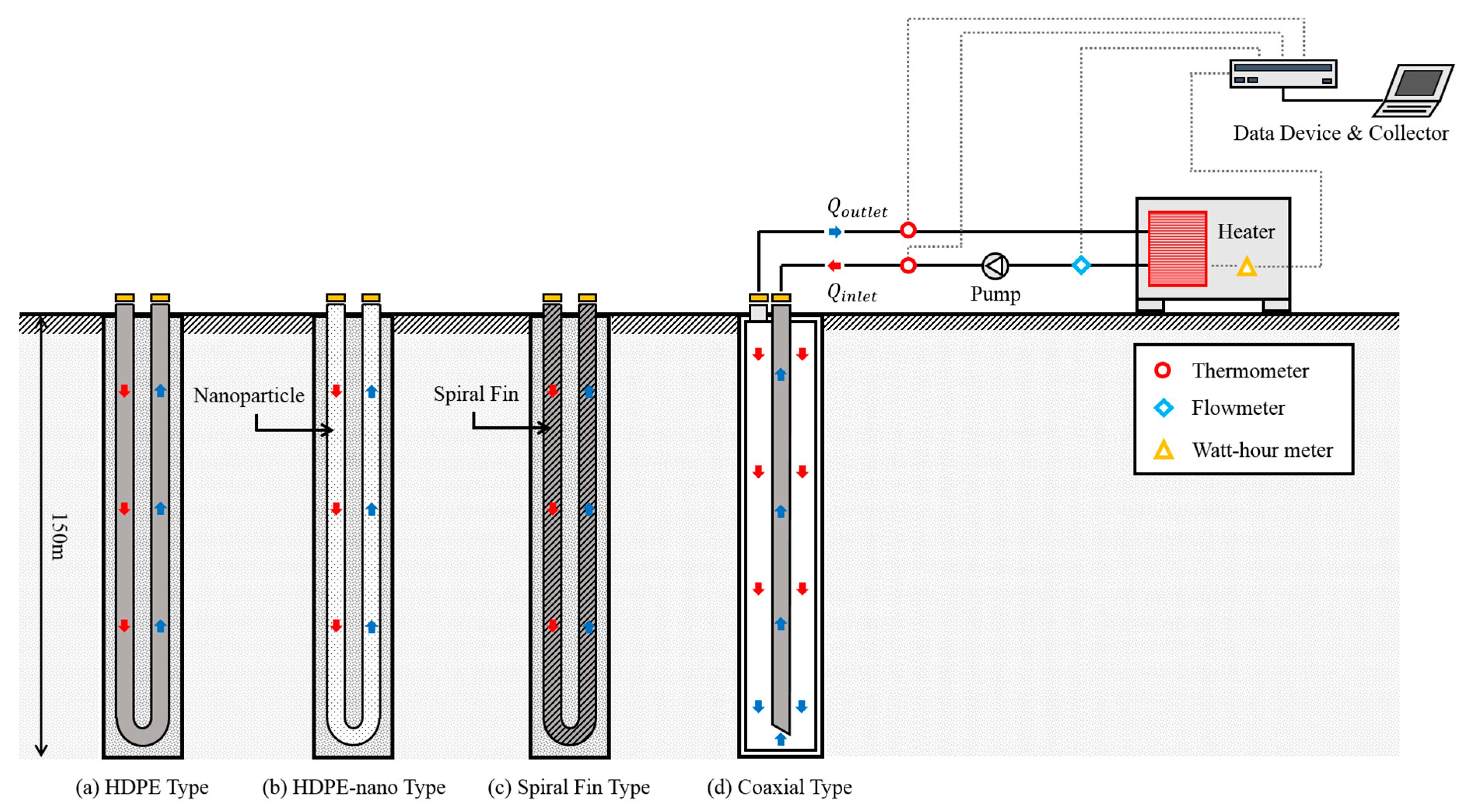
2.1. Overview of Thermal Response Test

The experimental site was located at Hoengseong county, Gangwon province, South Korea (latitude, 37.52; longitude, 127.90). According to geologic map of Korea institute of geoscience and mineral resources, the bed rock condition of the experimental site is the biotite granite and, the stratigraphic profile includes conglomerate, sandstone, and clay [13]. GHXs used in the field experiment consisted of four different types. They were installed a depth of 150 m. TRT was conducted to compare the thermal performance of each type of GHX. Figure 1 shows site plan of GHXs. These four types of GHXs were: general high-density polyethylene (HDPE) pipe, HDPE pipe with improved thermal conductivity using nano-particles (HDPE-nano), HDPE pipe using spiral fin (spiral fin type), and coaxial pipe. Two GHXs were installed for each type at the same site. In addition, GHXs were installed in locations within 10 × 10 m to construct the same underground thermal conditions. Separation distance was set to be 5000 mm to minimize thermal interference between GHXs. To accurately measure thermal performance of the same type of GHXs, the longest distance was installed diagonally. The arrangement of these GHXs is shown in Figure 1.
In Figure 1, A and A` are conventional HDPE pipes, B and B` are HDPE pipes using nano-particles, C and C` are HDPE pipes using spiral fin, and D and D` are coaxial pipes. The HDPE pipe using nano-particles has about 40% higher pipe thermal conductivity than the conventional HDPE pipe. In additions, the pipe using the spiral fin can improve convective heat transfer coefficient of circulating fluid through spiral fin [2,14].
Figure 2 shows schematic diagram for each type of GHX. The diameter ( D b ) of the borehole of the coaxial type (D, D`) GHX was 200 mm. The diameters of the borehole was 150 mm for other GHXs. For the coaxial type, the outer diameter of the GHX was 0.14 m, and the inner diameter of the GHX through which the circulating fluid flew inlet and outlet was 0.04 m. The outer diameter of (a) to (c) type was 0.05 m. The inner diameter was 0.0646 m for (a) and (c) type. It was 0.0454 m for (b) type. The GHX diameter was based on ISO 4427 specification of pipe dimensions [15]. Pipe types (a) and (c) had standard dimension ratio (SDR) of 17 while pipe type (b) had SDR of 11. The difference in inner diameter was 0.001 m. In Table 1 are summarized the main specifications of the boreholes and of the GHXs, among others the pipes thermal conductivity value.
Figure 3 shows schematic diagram of TRT with GHXs and TRT device. The TRT equipment was assembled under the same conditions as the GHX of the GSHP system actually installed. The TRT experiment equipment consisted of an operating part such as heat and circulating pump and control part for measuring temperature and flow rate. A thermocouple was installed on the inlet and outlet pipes to measure the temperature of the fluid heated in the heater and the temperature of the fluid returned from circulation in the pipe. The flowmeter was installed between the heater and the circulating pump to measure the flow rate of the circulating fluid injected into the borehole. The watt-hour meter was installed to measure the power supplied to the heater. Inlet and outlet temperatures of the circulating fluid, flow rate, and power of heater data were collected using data loggers and data acquisition devices.
Table 2 shows measurement error of measuring equipment. The measurement uncertainty of each measuring equipment was carried out in Korea laboratory accreditation scheme (KOLAS).

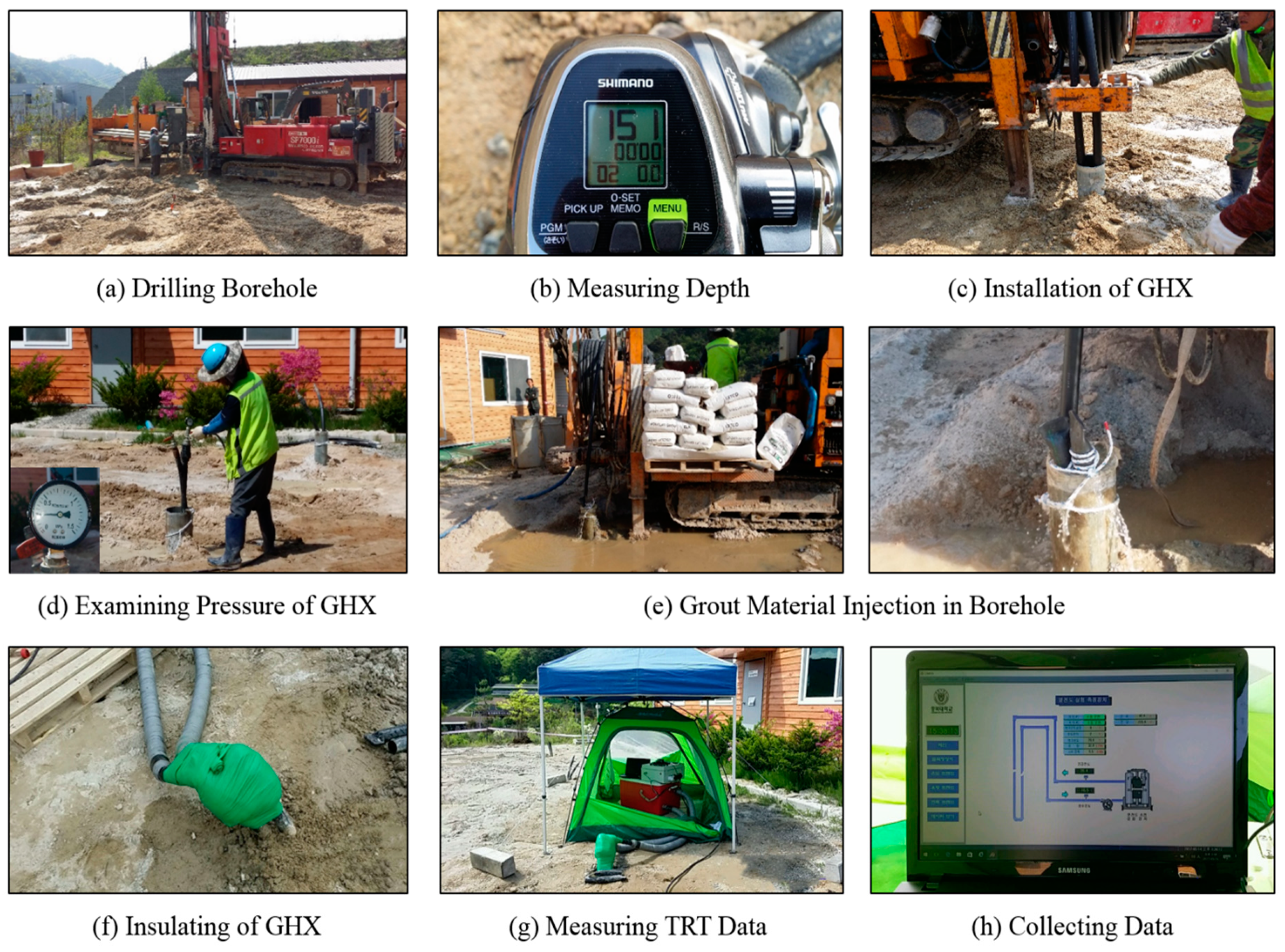
2.2. Assembly Procedure of the TRT

Eight 150-m deep GHXs were constructed in the same experimental site. The installation range of the GHX was 10 × 10 m. Figure 4 shows an overall procedure for assembling and conducting an in situ TRT. The assembly and construction of TRT consisted of nine stages. First, the experimental site of 100 m2 was constructed on the field area and eight holes were drilled using a drilling-machine. The depth of the borehole was then measured and GHX was inserted into the borehole. After inserting the GHX, borehole was grouted. The grout material was the same for all boreholes and bentonite was used. When the length of the GHX was 150 m or less, pipes were connected by thermal fusion method. After connecting the TRT device and the GHX, the inlet and the outlet of the GHX were insulated to minimize influence of external conditions such as ambient temperature. Through this process, inlet and outlet temperatures of circulating fluid and effective thermal conductivity of each GHX were measured.

3. Thermal Response Test

3.1. Standards of Thermal Response Test

In the design of vertical GSHP systems, it is critical to have accurate and detailed geological field investigation of ground and rock thermal properties [16]. Thermal properties can be evaluated by installing TRT equipment in the same borehole as planned for the GSHP system. In order to improve the accuracy of thermal properties data measured in the field, test specifications such as measurement method, analysis time, heat rate, and error were specified. At the American society of heating, refrigerating and air-conditioning engineers (ASHRAE), the test is performed for 36 to 48 h and the heat rate is recommended to be 50 to 80 W/m so that, peak load is expected in the GHX for an actual GSHP system [17]. Additionally, the accuracy of temperature measurement and collecting apparatus is specified to be 0.3 K with a standard deviation of input power of less than 1.5%. For TRT, a waiting period of five days is suggested for low-conductivity ground and grout material filled after the borehole while a delay period of three days is recommended for higher-conductivity.
On the other hand, the Korea energy agency (KEA) proposes TRT measurement standards for vertical GSHP systems [18]. It recommends that the heater should be continuously measured for 48 h after the power is on and measurement data should be collected with intervals of at least 10 min. It also recommends that the test should be conducted 72 h after completion of bentonite grouting and 14 days after cement grouting. It suggests that data for the initial 12 h should be excluded from calculation. Heat rate, measured temperature, and error of input power are specified as same as test specification recommended by ASHRAE.

3.2. Thermal Response Test Theory

Thermal properties of the underground are very important factors in the design of the GSHP system. Therefore, it is necessary to accurately measure underground thermal properties locally where the system is installed. The main output value of the response test includes the effective thermal conductivity and borehole thermal resistance. For measurement of GHX types, grout material, and groundwater flow effects are also important [19,20,21]. Heat transfer problem between the borehole and underground in the response test was evaluated based on the Kelvin line-source theory. This theory can approximate the borehole and the GHX with a single linear heat source for TRT verification. It is commonly adopted because it is a simple and convenient analysis. Ingersoll and Plass [22] have applied line source model for closed-loop GHX buried in the underground. Mogensen [23] has developed a model to estimate thermal conductivity and borehole thermal resistance of underground from field test and further suggested the concept of initial ignoring time (IIT) of TRT results.
The equation for temperature area as a function of time (t) and radius (r) around a line source model with constant heat injection rate (Q) can be utilized as an approach value of heat injection from the GHX
Δ T ( r , t ) = Q 4 π k r 2 4 π k e u u d u = Q 4 π k E 1 ( r 2 4 α t )
The exponential integral ( E 1 ) can be approximated by the following simple relationship for large value of the parameter ( α t / r 2 )
E 1 ( r 2 4 α t ) = ln ( 4 α t r 2 ) γ
where α is thermal diffusivity and γ is Euler’s constant ( γ = 0.5772 ) .
The fluid temperature considers heat transfer between the borehole and the fluid. Heat flux depends on thermal conductivity, heat capacity, and ground thermal diffusivity. It also adds thermal resistance ( R b ) effect between the fluid within the GHX and the borehole wall surface. Thus, a time-dependent fluid temperature equation can be described as
Δ T ( r , t ) = Q 4 π k ln t + { ln ( 4 α t r 2 ) γ } + Q × R b + T o
The only variable in Equation (3) is ln t . It can be expressed as follows by transforming constant ln t in a general linear equation.
y = m x + c
Therefore, it is possible to obtain a linear equation by measuring borehole fluid temperature over time, and plotting the fluid temperature and the ln t relation on coordinates. Calculating slope ( m ) of Equation (4), the thermal conductivity (k) can be determined.
k = Q 4 π m L b
Thermal conductivity (k) can be expressed by using slope (m) calculated in Equation (4), length of the borehole ( L b ), and heat energy (Q).

4. Results of Thermal Response Test
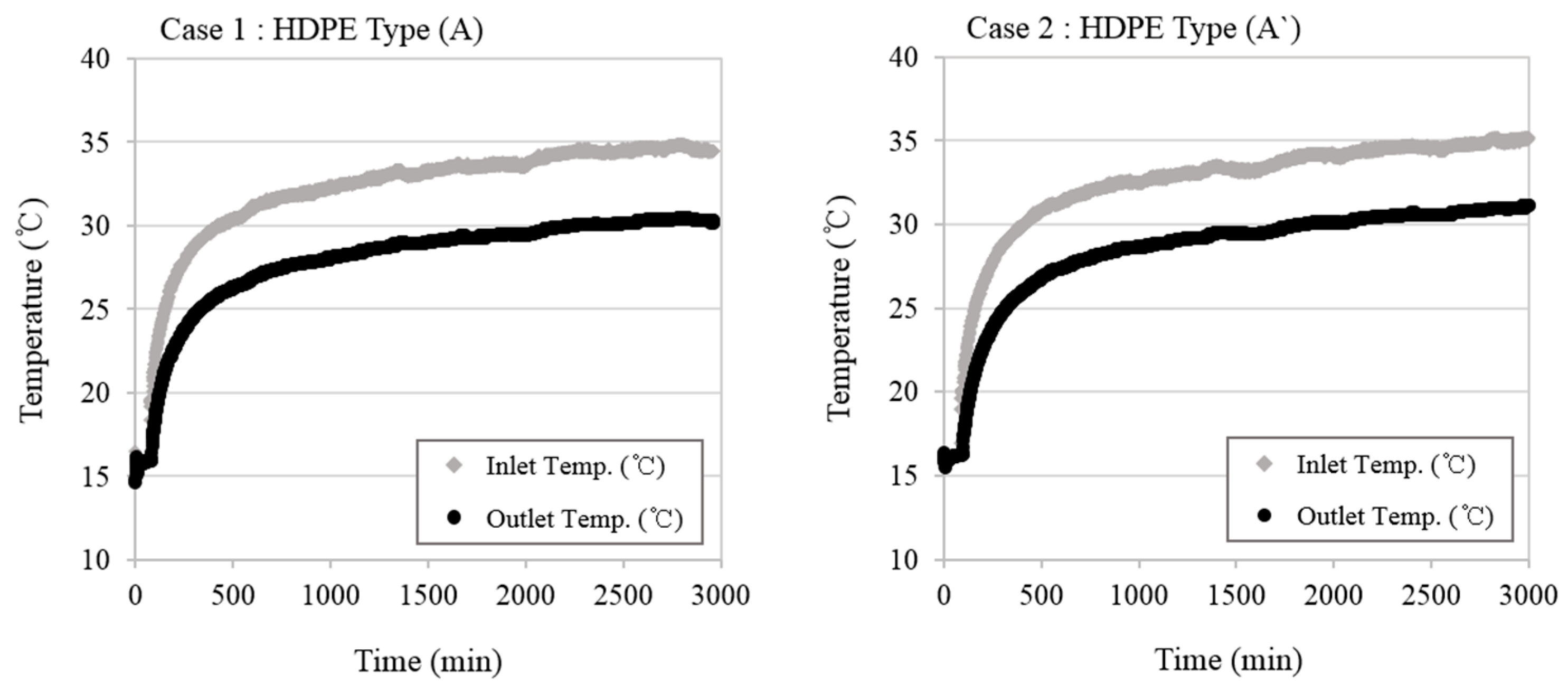
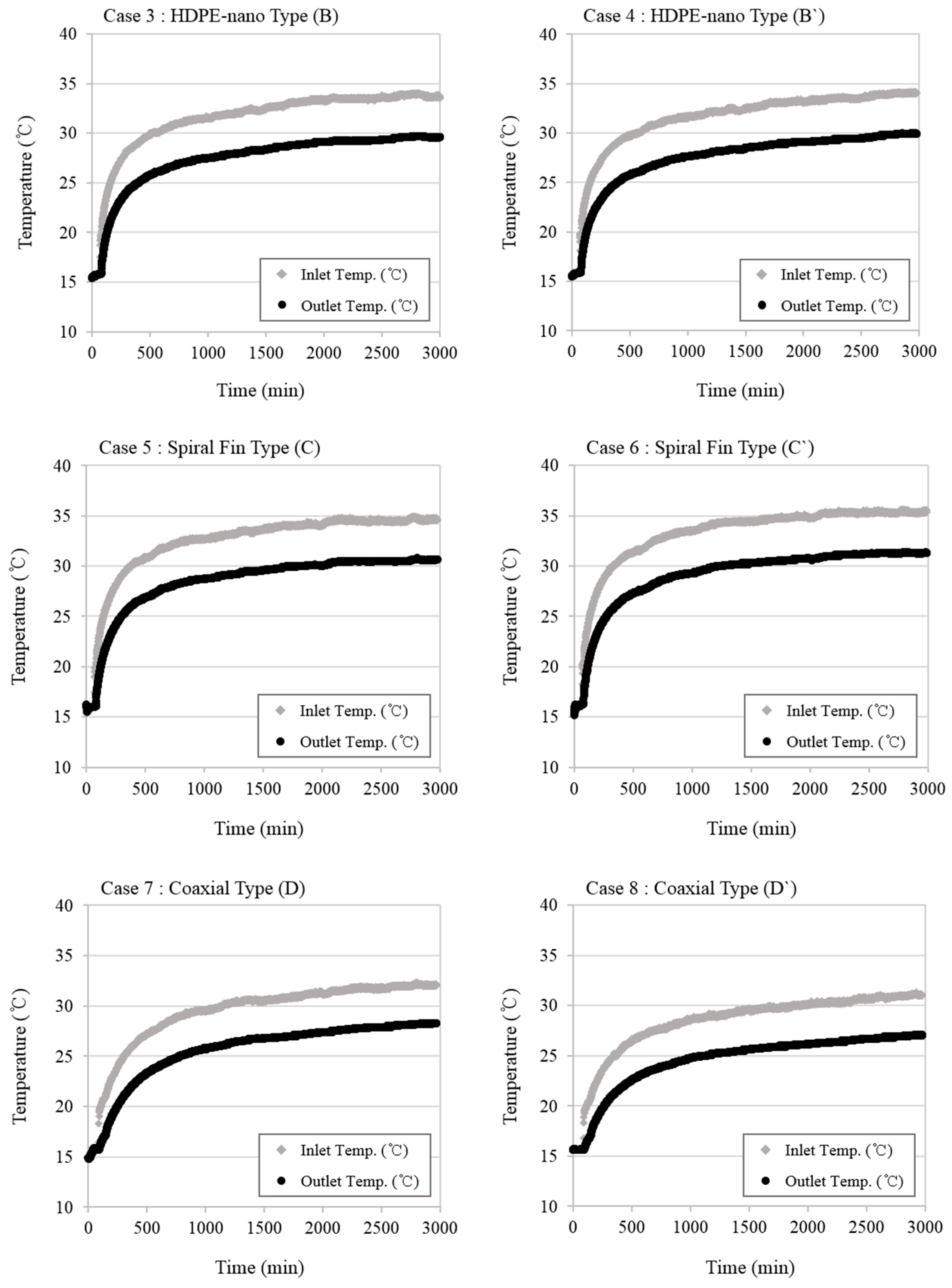
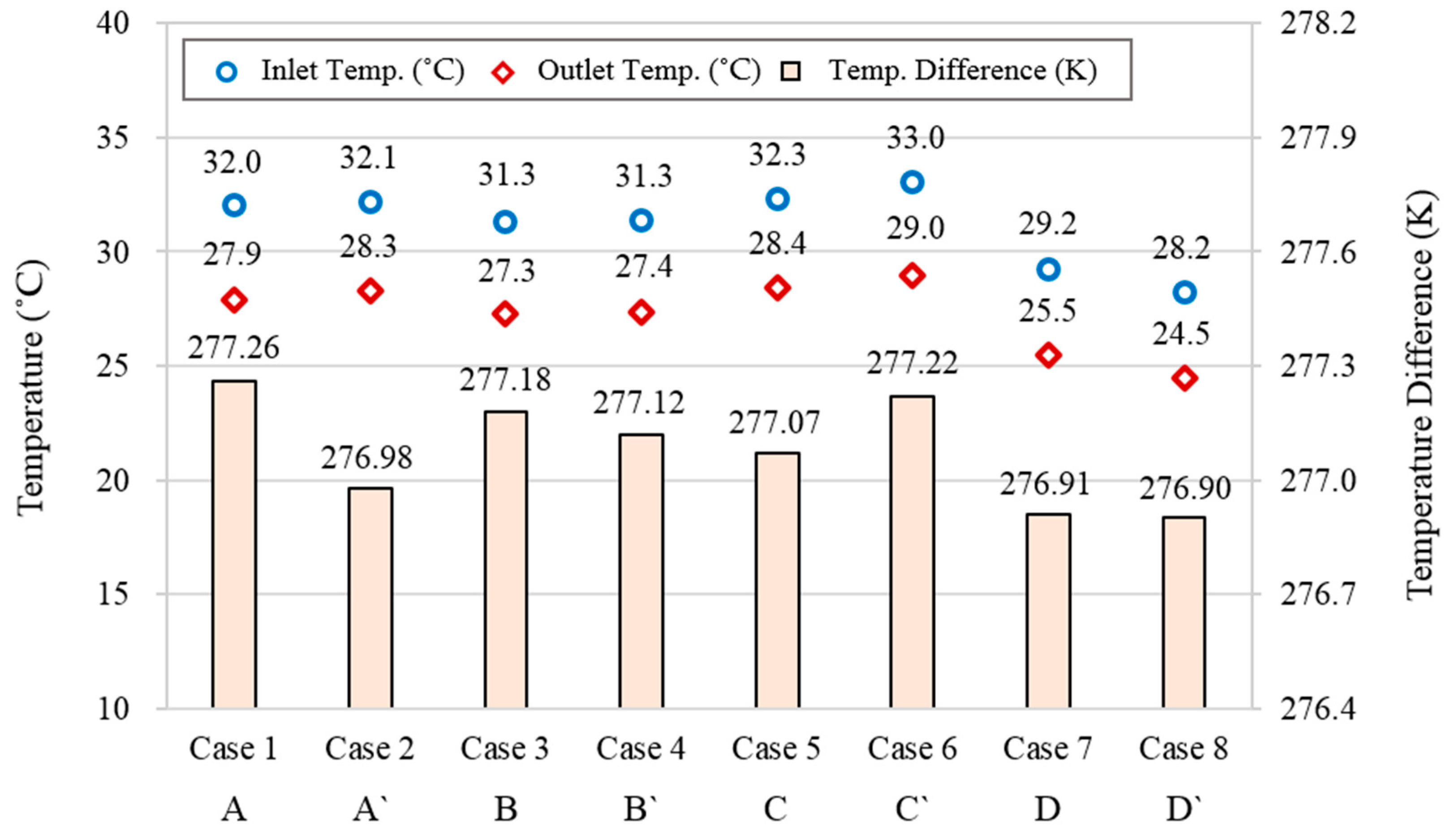
4.1. Temperature

In this study, TRT was conducted in the experimental site to evaluate thermal performance of the GHX according to pipe type. The TRT was a verification field test that evaluates thermal performance of the GHX by using temperature change of circulating fluid inside the pipe when constant heat was supplied to the borehole during the test time [24,25].
In this study, in order to accurately measure underground effective thermal conductivity, only the circulation pump was operated before the test. The fluid was circulated inside the GHX to remove foreign substance and air inside the pipe. When the temperature of the ground and rock reached a steady state by continuously circulating fluid for a certain period of time, inlet and outlet temperature of the circulating fluid, flow rate, and power of the heater were measured.
Table 3 shows experimental conditions of the TRT. The TRT measurement time was set to be 2880 min (48 h) for each GHX and the measurement time step was 1 min. Circulating fluid inside the borehole was water. The average flow rate of the circulating fluid was maintained at 33.6 l/min. The average initial temperature of ground and rock was 15.8 °C. The amount of heat to be injected into the borehole differed slightly for each GHX. The average amount of heat injection was 9342 W.
Figure 5 shows changes in inlet and outlet temperatures during the TRT. The circulating fluid temperature inside the GHX showed a rapid slope at the beginning of heat injection. Thus, at the beginning of the TRT, thermal diffusion was performed only in the GHX because the injected heat was utilized to heat the circulating fluid [26,27]. As time went by, temperature of the circulating fluid in the GHX gradually decreased. Physical properties of the ground affected the heat transfer performance as thermal diffusion proceeded from the GHX to the underground. When heat from the GHX was transferred to the ground and heat transfer almost reached equilibrium, the circulating fluid exhibited a constant rate of rise.
The initial temperature increase of the circulating fluid was different according to the type of GHX. However, in all cases, inlet and outlet temperature gradients of the circulating fluid were slightly different after 500 min. Especially, Case 7 (Coaxial type A) and Case 8 (Coaxial type A′) were relatively low initial temperature rate of rise compared to other cases. Thus, Case 7 and Case 8 indicated better thermal diffusion into the underground than other cases.

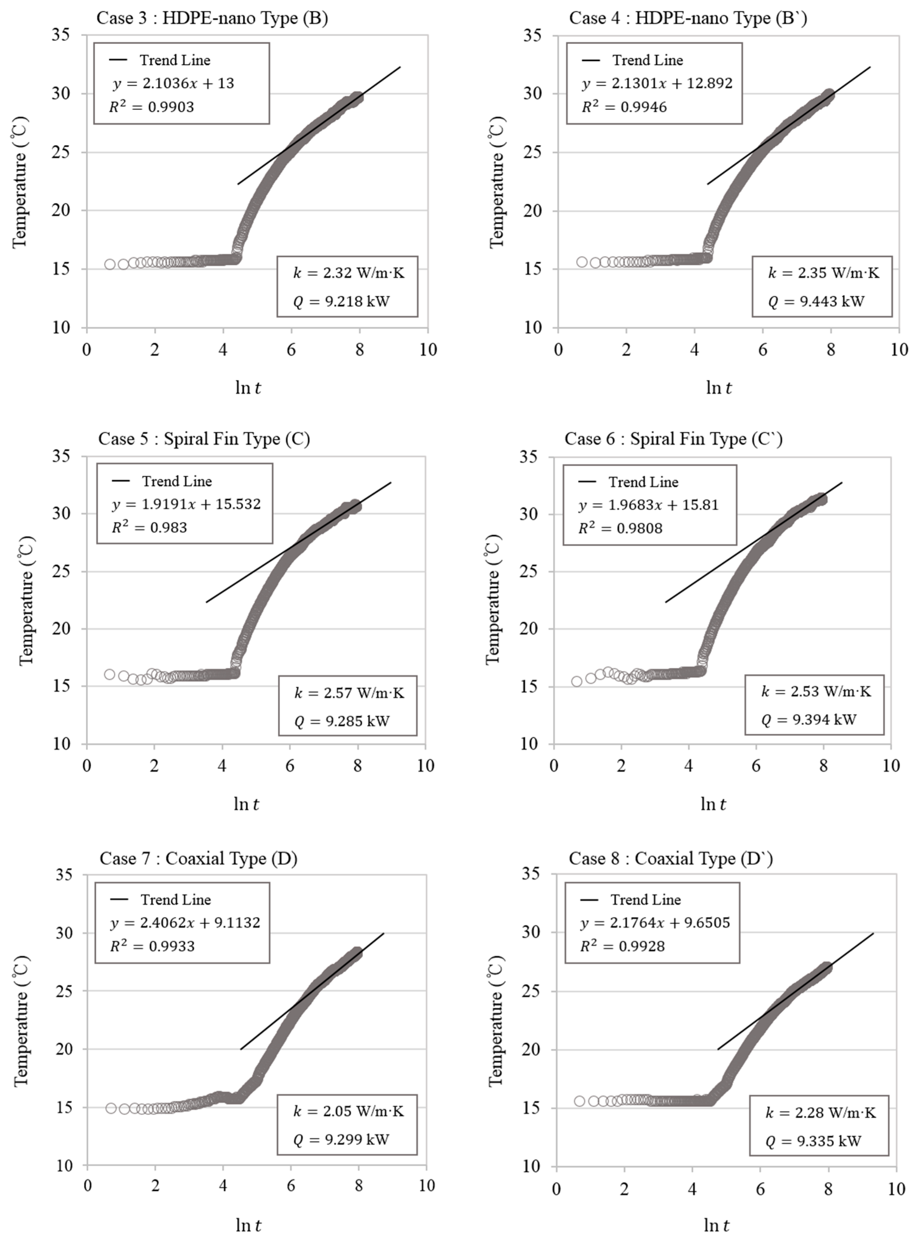
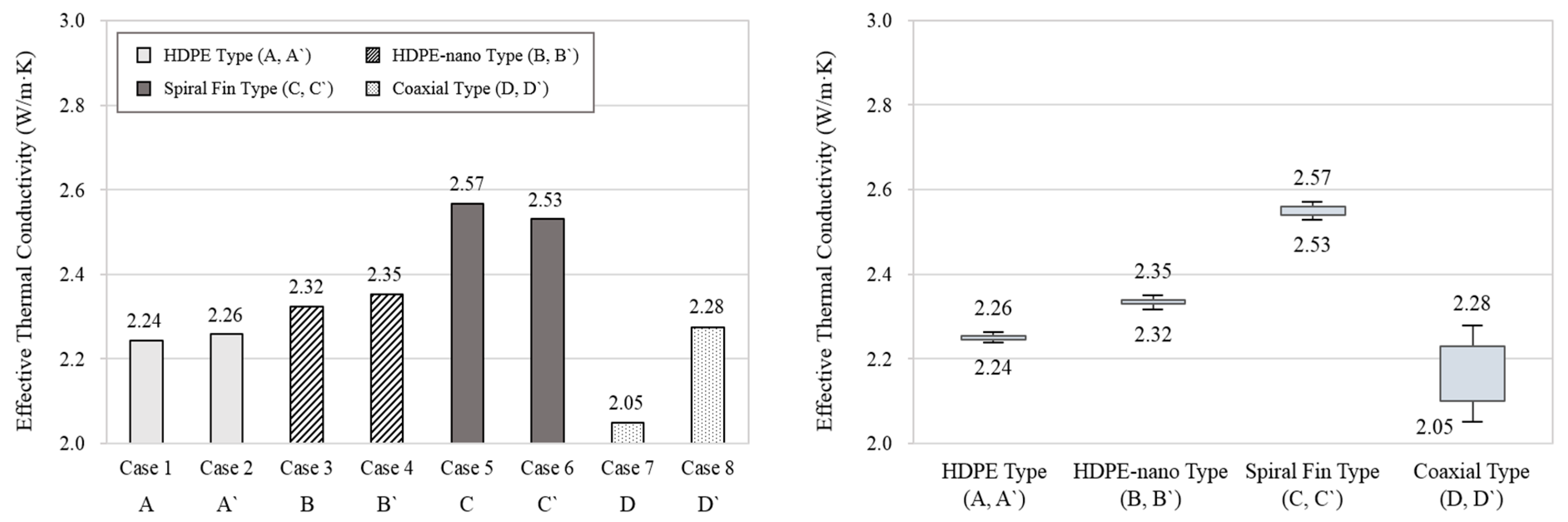
4.2. Effective Thermal Conductivity

The accuracy of the TRT is important because inlet and outlet temperatures measured at the beginning of the test reflect thermal response of the borehole inside [28]. Major errors such as inlet and outlet temperatures of circulating fluid and power of the heater in the field TRT occurred within the initial 12 h after the start of measurement. To ensure the reliability of measurement data, it is recommended to set the test measurement interval to be within 10 min and exclude the initial 12 h after the start of the test from analysis results [18,29,30].
Figure 6 shows the slope of natural logarithm verse outlet temperature for TRT. In this study, TRT measurement results excluding initial 12 h of data were based on the standard of the TRT in South Korea. Thus, effective thermal conductivity data from 36 to 48 h was used. Slope of effective thermal conductivity of HDPE types (i.e., Case 1 and Case 2) were 2.2481 and 2.1742, respectively. Average slopes of HDPE-nano types (i.e., Case 3 and Case 4) and spiral fin types (i.e., Case 5 and Case 6) were 2.1168 and 1.9437, respectively. Average slope of the coaxial type (i.e., Case 7 and Case 8) was 2.2913. Based on the slope calculation, the effective thermal conductivity can be determined according to Equation (5) and the results show that HDPE-nano type and spiral fin type had higher thermal conductivity than HDPE type, as hereafter described.
Effective thermal conductivities of conventional HDPE types were 2.24 W/m·K and 2.26 W/m·K, respectively, Average effective thermal conductivity of HDPE type was 2.25 W/m·K. Effective thermal conductivities of coaxial types were calculated to be 2.05 W/m·K and 2.28 W/m·K, respectively, with an average effective thermal conductivity of 2.16 W/m·K, that is 4.1% lower than that of HDPE type. Coaxial types is considered to have lower effective thermal conductivity than conventional HDPE type due to the diameter of borehole and borehole thermal resistance.
On the other hand, the HDPE-nano type and spiral fin type had higher effective thermal conductivity than the HDPE type of GHX, with average effective thermal conductivity calculated to be 2.34 W/m·K and 2.55 W/m·K, respectively. These average effective thermal conductivities were 3.9% and 13.2% higher, respectively, than that of HDPE type of GHX. The HDEP-nano type has higher pipe thermal conductivity than the conventional HDPE type. It can reduce borehole thermal resistance. Thus, its effective thermal conductivity is improved. For the spiral fin type, convective heat transfer coefficient of the circulating fluid is increased through the fin inside the GHX. Thus, its effective thermal conductivity is improved.

5. Discussion of Thermal Response Test

5.1. Temperature and Effective Thermal Conductivity

In this study, the same underground conditions and experimental conditions were taken into consideration. Inlet and outlet temperature changes of the circulating fluid and effective thermal conductivity according to the type of GHX were then measured.
Figure 7 shows average inlet and outlet temperatures according to GHX type. In case of the coaxial type (i.e., Case 7 and Case 8), the average inlet and outlet temperature difference of the circulating fluid was 276.91K (3.76 °C). For the HDPE type (i.e., Case 1 and Case 2), it was 277.12K (3.97 °C). The average inlet and outlet temperature difference of circulating fluid of the HDPE-nano type (i.e., Case 3 and Case 4) and the spiral fin type (i.e., Case 5 and Case 6) was both 277.15 K (4.0 °C). The HDPE-nano type and the spiral fin type had higher inlet and outlet temperature difference than the HDPE type, but the outlet temperature decrease in the coaxial type is higher than in the others GHX type.
The coaxial type had poorer thermal performance than other types of GHXs. However, it is difficult to accurately analyze the cause of such difference in thermal performance depending on the type of GHX based on results of TRT such as inlet and outlet temperatures of the circulating fluid and effective thermal conductivity. To understand the difference of thermal performance in detail, Section 5.2 describes the effect of borehole thermal resistance on the type of GHX.
Figure 8 shows effective thermal conductivity according to type of GHXs. Average effective thermal conductivities for HDPE, HDPE-nano, spiral fin, and coaxial types of GHXs were 2.25 W/m·K, 2.34 W/m·K, 2.55 W/m·K, and 2.16 W/m·K, respectively. The HDEP-nano type and spiral fin type showed 3.9% and 13.2% higher average effective thermal conductivity than the conventional HDPE type, respectively. On the other hand, the coaxial type had lower average effective thermal conductivity than the HDPE type by 4.1%.

5.2. Borehole Thermal Resistance

In vertical GSHP system design, borehole thermal resistance is a very important factor. Borehole thermal resistance is determined by characteristics of the grout material, the circulating fluid, and the pipe. It has a great influence on the thermal performance of GHX. Therefore, in this study, borehole thermal resistance calculation was performed to analyze inlet and outlet temperatures and effective thermal conductivity of circulating fluid according to the type of GHX. Equations (6) to (11) were used to calculate borehole thermal resistance.
Equation (6) can be indicated as Equation (3) for borehole thermal resistance ( R b ).
R b = 1 4 π k [ Δ T m ln ( 4 α t γ r 2 ) ]
Borehole thermal resistance ( R b ) in Equation (6) can be written as in Equation (7) which includes grout thermal resistance ( R g ), circulating fluid thermal resistance ( R f ), and pipe thermal resistance ( R p ) [31,32].
R b = R g + R f + R p
Grout thermal resistance ( R g ) can be calculated using borehole resistance shape factors ( β 0 ,   β 1 ) developed by Remmund, borehole diameter ( d b ), pipe inner diameter ( d o ), and grout thermal conductivity ( k g ) [33].
R g = β 0 ( d b d o ) β 1 × 1 k g
The borehole resistance shape factor for U-tube locations in vertical borehole was determined by borehole shape and U-tube location [33]. In case of HDPE type, HDPE-nano type, and spiral fin type, borehole resistance shape factors were determined using borehole configuration B in Figure 9. However, in case of the coaxial type, grout thermal resistance ( R g ) for the concentric arrangement was calculated using Equation (9) proposed by Kavanaugh [34].
R g = ln ( d b d o ) 2 π k g
The thermal resistance due to circulating fluid in the GHX was calculated using Equation (10). It can be written using pipe inner diameter ( d i ), and convective heat transfer coefficient ( h f ) of the circulating fluid.
R f = 1 2 π d i h f
The circulating fluid thermal resistance has relatively lower effect on borehole thermal resistance than pipe thermal resistance and grout thermal resistance. However, the circulating fluid thermal resistance is calculated differently according to the type of the GHX. Thus, it was considered for accurate results. On the other hand, pipe thermal resistance using a single U-tube is described in Equation (11). It can be calculated using pipe outer diameter ( d o ), pipe inner diameter ( d i ), and pipe thermal conductivity ( k p ).
R p = ln ( d o d i ) 2 π k p
Figure 9 shows borehole thermal resistance according to type of GHX. Average borehole thermal resistances for HDPE, HDPE-nano, spiral fin, and coaxial types of GHXs were 0.1829 m·K/W, 0.1810 m·K/W, 0.1808 m·K/W, and 0.3059 m·K/W, respectively. Borehole thermal resistances of Case 7 and Case 8 (coaxial type) were the highest. The coaxial type (i.e., Case 7 and Case 8) showed increased of average borehole thermal resistance by 67.3% compared to the HDPE type (Case 1 and Case 2) On the other hand, the average borehole thermal resistance of the HDPE-nano type (Case 3 and Case 4) was 1.02% lower than that of the HDPE type (i.e., Case 1 and Case 2). The average borehole thermal resistance of the spiral fin type (i.e., Case 7 and Case 8) was 1.13% lower than that of the HDPE type (Case 3 and Case 4). In Table 4 are summarized the thermal resistance value such as grout, fluid, pipe, and borehole for all of GHXs types.
The coaxial type had lower grout thermal resistance than other types of GHXs. However, because its pipe outer diameter was large and its pipe inner diameter was small, its pipe thermal resistance and thermal resistance of the circulating fluid were calculated to be higher than those of other cases. Meanwhile, the borehole thermal resistance of HDPE-nano type and spiral fin type showed similar values. The HDPE-nano type was able to reduce pipe thermal resistance compared to conventional HDPE type through its improved thermal conductivity of the pipe material, but its effect was not significant. In addition, the spiral fin type was confirmed to have little thermal resistance to the circulating fluid due to its improved convective heat transfer coefficient of fluid. The results confirmed that the borehole thermal resistance was decreased when thermal conductivity of the GHX and convective heat transfer coefficient of circulating fluid inside the GHX present the highest values. These results also confirmed that borehole thermal resistance could vary depending on the type of GHX, thus affecting results of TRT.

6. Conclusions

In this study, thermal performances of various types of vertical GHX were evaluated in the field with the same field conditions. Four types of GHX were constructed in the same field. Inlet and outlet temperatures of the circulating fluid and effective thermal conductivity were calculated through TRT. In addition, borehole thermal resistance was calculated to comparatively analyze the correlation of thermal performance with each GHX. Results of this study are summarized as follows.
(1) Average effective thermal conductivities of the HDPE-nano type and spiral fin type were 3.9% and 13.2% higher than the HDPE type, respectively. On the other hand, average effective thermal conductivity of the coaxial type was lower than that of the HDPE type by 4.1%. These results indicate that improvement of convective heat transfer coefficient of circulating fluid and the pipe thermal conductivity can affect the effective thermal conductivity.
(2) Borehole thermal resistance was calculated to be the highest at 0.3059 m·K/W with the coaxial type. This is because its pipe outer diameter is increased and its inner diameter is decreased. Thus, pipe thermal resistance and thermal resistance of the circulating fluid are increased.
(3) Borehole thermal resistances of the HDPE-nano type and the spiral fin type were decreased by 1.02% and 1.13%, respectively, compared to that of the conventional HDPE type. This is because pipe thermal resistance and fluid thermal resistance are reduced. This result confirms that borehole thermal resistance varies depending on the type of GHX, thus affecting results of TRT. In the result, it was found that the average borehole thermal resistance can be important factor in TRT but the effect of increased thermal conductivity of pipe material itself was not significant.
In the future, we will build a geothermal heat pump system using HDPE type and spiral type to perform system performance analysis considering load pattern of actual building.

Author Contributions

The authors S.M.B. and Y.N. analyzed TRT data and wrote the full manuscript. The authors J.M.C. and K.H.L. checked the results and reviewed the whole manuscript. The author J.S.C. constructed experimental equipment.

Funding

This research was funded by the Korea Institute of Energy Technology Evaluation and Planning (KETEP) and the Ministry of Trade, Industry & Energy (MOTIE) of the Republic of Korea (No. 20163030111350)

Acknowledgments

This work was supported by the Korea Institute of Energy Technology Evaluation and Planning (KETEP) and the Ministry of Trade, Industry & Energy (MOTIE) of the Republic of Korea (No. 20163030111350).

Conflicts of Interest

The authors declare no conflict of interest.

References

  1. Ji, W.T.; Zhang, D.C.; He, Y.L.; Tao, W.Q. Prediction of fully developed turbulent heat transfer of international helically ribbed tubes—An extension of Gnielinski equation. Int. J. Heat Mass Transf. 2012, 55, 1375–1384. [Google Scholar] [CrossRef]
  2. Mensah, K.; Choi, J.M. Numerical analysis on the heat transfer characteristics of HDPE pipe with the variation of geometries for ground loop heat exchanger. Trans. Korea Soc. Geotherm. Energy Eng. 2016, 12, 33–39. [Google Scholar] [CrossRef]
  3. Saeidi, R.; Noorollahi, Y.; Esfahanian, V. Numerical simulation of a novel spiral type ground heat exchanger for enhancing heat transfer performance of geothermal heat pump. Energy Convers. Manag. 2018, 168, 296–307. [Google Scholar] [CrossRef]
  4. Oh, K.; Lee, S.; Park, S.; Han, S.I.; Choi, H. Field experiment on heat exchange performance of various coaxial-type ground heat exchangers considering construction conditions. Renew. Energy 2018. [Google Scholar] [CrossRef]
  5. Holmberg, H.; Acuña, J.; Næss, E.; Sønju, O.K. Thermal evaluation of coaxial deep borehole heat exchangers. Renew. Energy 2016, 97, 65–76. [Google Scholar] [CrossRef]
  6. Chen, S.; Mao, J.; Han, X. Heat transfer analysis of a vertical ground heat exchanger using numerical simulation and multiple regression model. Energy Build. 2016, 129, 81–91. [Google Scholar] [CrossRef]
  7. Pu, L.; Qi, D.; Li, K.; Tan, H.; Li, Y. Simulation study on the thermal performance of vertical U-tube heat exchangers for ground source heat pump system. Appl. Therm. Eng. 2015, 79, 202–213. [Google Scholar] [CrossRef]
  8. Li, M.; Zhang, L.; Liu, G. Estimation of thermal properties of soil and backfilling material from thermal response tests (TRTs) for exploiting shallow geothermal energy: Sensitivity, identifiability, and uncertainty. Renew. Energy 2019, 132, 1263–1270. [Google Scholar] [CrossRef]
  9. Esen, H.; Inalli, M. In-situ thermal response test for ground source heat pump system in Elazig, Turkey. Energy Build. 2009, 41, 395–401. [Google Scholar] [CrossRef]
  10. Franco, A.; Moffat, R.; Toledo, M.; Herrera, P. Numerical sensitivity analysis of thermal response tests (TRT) in energy piles. Renew. Energy 2016, 86, 985–992. [Google Scholar] [CrossRef]
  11. Lee, C.; Park, M.; Nguyen, T.B.; Sohn, B.; Choi, J.M.; Choi, H. Performance evaluation of closed-loop vertical ground heat exchangers by conducting in-situ thermal response tests. Renew. Energy 2012, 42, 77–83. [Google Scholar] [CrossRef]
  12. Miyara, A. Thermal performance and pressure drop of spiral-tube ground heat exchangers for ground-source heat pump. Appl. Therm. Eng. 2015, 90, 630–637. [Google Scholar] [CrossRef]
  13. Korea Institute of Geoscience and Mineral Resources. Geoscience Information System; Korea Institute of Geoscience and Mineral Resources: Daejeon, Korea, 2014. [Google Scholar]
  14. Bouhachina, B.; Saim, R.; Oztop, H.F. Numerical investigation of a novel tube design for the geothermal borehole heat exchanger. Appl. Therm. Eng. 2015, 79, 153–162. [Google Scholar] [CrossRef]
  15. International Organization for Standardization. ISO 4427-1: Plastics Piping Systems—Polyethylene (PE) Pipes and Fittings for Water Supply; International Organization for Standardization: Geneva, Switzerland, 2007. [Google Scholar]
  16. Kavanuagh, S.; Rafferty, K. Ground-Source Heat Pumps: Design of Geothermal Systems for Commercial and Institutional Buildings; ASHRAE: Atlanta, GA, USA, 1997. [Google Scholar]
  17. ASHRAE. ASHRAE Handbook: HVAC Applications; ASHRAE: Atlanta, GA, USA, 2007. [Google Scholar]
  18. Korea Energy Agency. Construction Standards for New and Renewable Energy Equipment; Korea Energy Agency: Kyeonggi-do, Korea, 2017. [Google Scholar]
  19. Austin, W.A. Development of an In Situ System for Measuring Ground Thermal Properties. Master’s Thesis, Oklahoma State University, Stillwater, OK, USA, 1998. [Google Scholar]
  20. Gehlin, S. Thermal Response Test Method Development and Evaluation. Ph.D. Thesis, Luleå University of Technology, Luleå, Sweden, 2002. [Google Scholar]
  21. Bujok, P.; Grycz, D.; Klempa, M.; Kunz, A.; Prozer, M.; Pytlik, A.; Rozehnal, Z.; Vojcinák, P. Assessment of the influence of shortening the duration of TRT(thermal response test) on the precision of measured values. Energy 2014, 64, 120–129. [Google Scholar] [CrossRef]
  22. Ingersoll, L.R.; Plass, H.J. Theory of the ground pipe heat source for the heat pump. ASHVE Trans. 1948, 54, 339–348. [Google Scholar]
  23. Mogensen, P. Fluid to duct wall heat transfer in duct system heat storages. In Proceedings of the International Conference on Subsurface Heat Storage in Theory and Practice, Stockholm, Sweden, 6–8 June 1983; pp. 652–657. [Google Scholar]
  24. Sharqawy, M.H.; Mokheimer, E.M.; Habib, M.A.; Badr, H.M.; Said, S.A.; Al-Shayea, N.A. Energy, exergy and uncertainty analyses of the thermal response test for a ground heat exchanger. Int. J. Energy Res. 2008, 33, 582–592. [Google Scholar] [CrossRef]
  25. Wanger, R.; Clauser, C. Evaluating thermal response tests using parameter estimation for thermal conductivity and thermal capacity. J. Geophys. Eng. 2005, 2, 349–356. [Google Scholar]
  26. Chang, G.S.; Kim, M.J.; Kim, Y.J. A study on the thermal characteristics of horizontal ground heat exchanger using thermal response test. J. Korea Acad.-Ind. Cooper. Soc. 2016, 17, 24–30. [Google Scholar]
  27. Hwang, S.; Ooka, R.; Nam, Y. Evaluation of estimation method of ground properties for the ground source heat pump system. Renew. Energy 2010, 35, 2123–2130. [Google Scholar] [CrossRef]
  28. Signorelli, S.; Bassetti, S.; Pahud, D.; Kohl, T. Numerical evaluation of thermal response test. Geothermics 2007, 36, 141–166. [Google Scholar] [CrossRef]
  29. Lee, S.K.; Woo, J.S.; Kim, D.K. A study of determining initial ignoring time of line source model used in estimating the effective soil formation thermal conductivities. J. Energy Eng. 2008, 17, 167–174. [Google Scholar]
  30. Chang, G.S.; Kim, M.J.; Kim, Y.J. A study on the determining initial ignoring time for the analysis of ground thermal conductivity of SCW Type ground heat exchanger. Korean J. Air-Cond. Refrig. Eng. 2014, 26, 453–459. [Google Scholar]
  31. Sohn, B. Evaluation of ground effective thermal conductivity and borehole effective thermal resistance from simple line-source model. Korean J. Air-Cond. Refrig. Eng. 2007, 19, 512–520. [Google Scholar]
  32. Sohn, B. Evaluation of ground effective thermal properties and effect of borehole thermal resistance on performance of ground heat exchanger. Trans. Korea Soc. Geotherm. Energy Eng. 2012, 8, 32–40. [Google Scholar]
  33. Remmund, C. Borehole Thermal Resistance: Laboratory and Field Studies. In Proceedings of the ASHRAE Transactions, Seattle, WA, USA; 1999; Volume 105. [Google Scholar]
  34. Kavanaugh, S.; Rafferty, K. Geothermal heating and cooling: Design of ground-source heat pump systems. In Proceedings of the ASHRAE Transactions, New York, NY, USA; 2014; Volume 120. [Google Scholar]
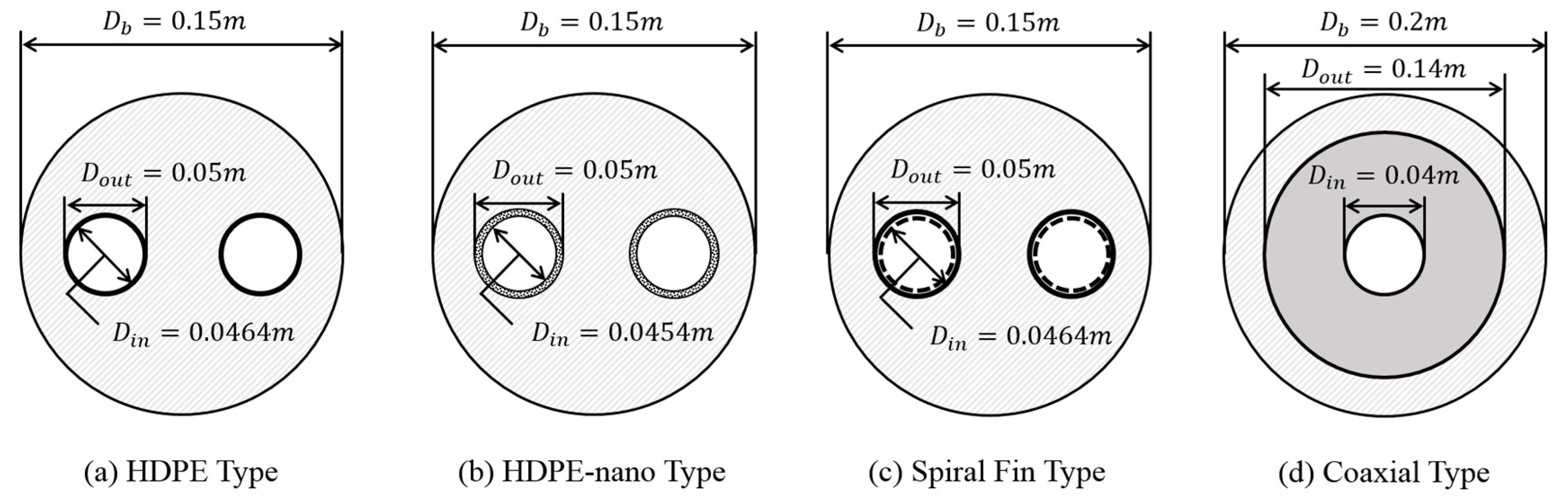
Figure 1. Site plan of GHXs.
Energies 12 00651 g001
Figure 2. Schematic diagram for each type of GHX.
Energies 12 00651 g002
Figure 3. Schematic diagram of TRT with GHXs and TRT device.
Energies 12 00651 g003
Figure 4. Overall procedure for assembling and conducting in situ TRT.
Energies 12 00651 g004
Figure 5. Results of TRT for temperature change in inlet and outlet.
Energies 12 00651 g005aEnergies 12 00651 g005b
Figure 6. Results of TRT for trend line according to line slope and outlet temperature.
Energies 12 00651 g006aEnergies 12 00651 g006b
Figure 7. Average inlet and outlet temperatures according to type of GHX.
Energies 12 00651 g007
Figure 8. Effective thermal conductivity according to type of GHX.
Energies 12 00651 g008
Figure 9. Borehole thermal resistance according to type of GHX.
Energies 12 00651 g009
Table 1. Specifications of GHXs.
Type of GHXsBorehole Diameter (m)Pipe Diameter (m)Thermal Conductivity (W/m·K)
HDPE Type0.15 d o = 0.05, d i = 0.0464 0.4
HDPE-Nano Type0.15 d o = 0.05, d i = 0.04540.55
Spiral Fin Type0.15 d o = 0.05, d i = 0.04640.4
Coaxial Type0.2 d o = 0.14, d i = 0.040.4
Table 2. Measurement error of measuring equipment.
ItemMeasuring EquipmentMeasurement Error
Flow RateFlowmeter (FLOW-300-25A)± 0.28%
Power ConsumptionAC Ammeter (MT4Y-AA-43)± 0.02 A
AC Voltmeter (MT4Y-AV-34)± 0.3 V
DC Ammeter (CM1-AD04VI)± 0.2 mA
Wattmeter (DPM-TWAT-S1B1B1)± 0.01 kW
TemperatureThermometer (PT100)± 0.1 °C
Data CollectorData Logger (CM1-RD04A)± 0.2 °C
Table 3. Experimental conditions of the TRT.
Test ConditionsValue
Measurement Time2880 min
Time Step1 min
Fluid TypeWater
Average Flow Rate33.6 l/min
Average Initial Ground Temp.15.8 °C
Average Amount of Heat Injection9342 W
Table 4. Thermal resistance for all of GHXs types
Grout Thermal Resistance
(m·K/W)
Fluid Thermal Resistance
(m·K/W)
Pipe Thermal Resistance
(m·K/W)
Borehole Thermal Resistance
(m·K/W)
Case 10.15070.00250.02970.1829
Case 20.15070.00240.02970.1828
Case 30.15070.00250.02790.1811
Case 40.15070.00240.02790.1810
Case 50.15070.00040.02970.1808
Case 60.15070.00040.02970.1808
Case 70.07670.00650.22270.3059
Case 80.07670.00650.22270.3059

