Article

Thermoelectric Energy Recovery in a Light-Duty Diesel Vehicle under Real-World Driving Conditions at Different Altitudes with Diesel, Biodiesel and GTL Fuels

by
Reyes García-Contreras
1,
Andrés Agudelo
2,
Arántzazu Gómez
1,*,
Pablo Fernández-Yáñez
1,
Octavio Armas
1,* and
Ángel Ramos
3
1
Departamento de Mecánica Aplicada e Ingeniería de Proyectos, Campus de Excelencia Internacional en Energía y Medioambiente, Escuela de Ingeniería Industrial, Universidad de Castilla-La Mancha, Av. Carlos III, s/n, 45071 Toledo, Spain
2
Departamento de Ingeniería Mecánica, Universidad de Antioquia, Calle 70, No. 52-21, 050010 Medellín, Colombia
3
Campus de Excelencia Internacional en Energía y Medioambiente, Escuela Técnica Superior de Ingenieros Industriales, Universidad de Castilla-La Mancha, Av. Camilo José Cela s/n, 13071 Ciudad Real, Spain
*
Authors to whom correspondence should be addressed.
Energies 2019, 12(6), 1105; https://doi.org/10.3390/en12061105
Submission received: 30 January 2019 / Revised: 7 March 2019 / Accepted: 14 March 2019 / Published: 21 March 2019

Abstract

:
This work focuses on the potential for waste energy recovery from exhaust gases in a diesel light-duty vehicle tested under real driving conditions, fueled with animal fat biodiesel, Gas To Liquid (GTL) and diesel fuels. The vehicle was tested following random velocity profiles under urban driving conditions, while under extra-urban conditions, the vehicle followed previously defined velocity profiles. Tests were carried out at three different locations with different altitudes. The ambient temperature (20 ± 2 °C) and relative humidity (50 ± 2%) conditions were similar for all locations. Exergy analysis was included to determine the potential of exhaust gases to produce useful work in the exhaust system at the outlet of the Diesel Particle Filter. Results include gas temperature registered at each altitude with each fuel, as well as the exergy to energy ratio (percentage of energy that could be transformed into useful work with a recovery device), which was in the range of 20–35%, reaching its maximum value under extra-urban driving conditions at the highest altitude. To take a further step, the effects of fuels and altitude on energy recovery with a prototype of a thermoelectric generator (TEG) were evaluated.

1. Introduction

One of the main strategic goals worldwide is the increase in the energy efficiency in order to reduce the demand for fossil fuels and the associated pollution. In Europe, Directive 2009/28/EC on the promotion of the use of energy from renewable sources sets of a saving of 20% on energy consumption through increased energy efficiency as the target for 2020 [1]. In this sense, the transport sector optimization, especially light-duty diesel fleet, is essential due to its overall high energy consumption and environmental implications. High compression ratios or the development of new injection strategies involving high pressures and split injections have improved the energy efficiency of diesel engines [2,3]. Different alternative fuels have been examined in order to reduce pollutant emissions without penalizing engine performance [4,5,6]. However, despite the efficiency increase, approximately one-third of the fuel energy in a diesel engine is lost through exhaust gases, which implies a significant potential for heat recovery. In order to recover part of this waste heat, several devices have been tested, the Organic Rankine Cycles (ORC) [7], the electric turbo-generation (ETG), also identified as Mechanical Generator Unit-Heat (MGU-H), used in formula one [8], and thermoelectric generators (TEG) being the most promising techniques [9]. An ORC uses waste heat to produce mechanical power with relatively high thermodynamic performance [10]. However, the weight and space requirements make these devices suitable only for medium–large vehicles. These drawbacks can be solved by ETG and/or TEG in light-duty vehicles. ETG can be used at high temperatures after the engine cylinder outlet, while TEG can be used in the zone of medium-low exhaust temperature downstream of emissions after-treatment devices. TEG are based on the Seebeck effect for direct electricity production between two heat sources at different temperatures. Although they have low efficiency and problems due to the increase in the back pressure in the exhaust pipe [11], TEG seems to be the most suitable alternative for energy recovery in light-duty vehicles, where there are space and weight restrictions [12,13,14,15].
The exhaust temperature in passenger light-duty cars is lower than that obtained in heavy-duty trucks. In addition, it was found that gasoline light-duty engines have more potential for thermoelectric production than diesel light-duty engines [16]. It is important to choose the most appropriate TEG device, as well as its location on the exhaust system. Exergy analysis can be a valuable tool to accomplish this task, given that it determines the amount of heat loss from exhaust gases that can be converted into useful work [17]. Several works have evaluated the possibility of using TEG for waste heat recovery in passenger vehicles. Kishita et al. [18] reported that commercially available thermoelectric materials may reach top conversion efficiencies of about 7.2%. Yu et al. [19] stated that, for automotive applications, this efficiency is in the range of 5–8%, while Twaha et al. [20] reported an efficiency of 5.35% for vehicle exhaust gas energy recovery. The materials of TEG devices also have an influence on their efficiency. In the study of Demir et al. [21], three different Perovskite-type oxides combined thermoelectric materials were evaluated at different exhaust gas temperatures. Results showed that the performance of these oxides materials was poorer than that related to traditional thermoelectric materials (Bi2Te3). Kempf and Zhang [22] evaluated strategies to optimize TEG configuration and heat exchanger design by means of a simulation of TEG performance in a spark ignition vehicle under highway driving conditions (107 ± 23 km/h). Massaguer et al. [23] developed a method to evaluate the fuel economy of automotive thermoelectric generators under steady state modes and Fernández-Yáñez et al. [24] optimized a TEG for a light-duty diesel engine under urban and extra-urban driving conditions by means of a factorial design of experiments aided by CFD simulations.
Studies applying exergy analysis on steady-state diesel engine conditions found that the maximum exergy efficiencies of the engine can be reached at high load and at medium–high engine speeds [25,26]. These operating modes are also the most suitable for exhaust energy harvesting [27].
Although steady state analyses provide information about energy recovery, the results are not representative of transient engine operation, which is characteristic of real driving conditions. Studies in spark ignition and diesel engines under the new European Driving Cycle (NEDC) show that the highest peak of exergy rate of exhaust gases can be found during extra-urban driving conditions due to higher mass flow rate and temperature of exhaust gases [28,29].
Caliskan [30] showed that the exergy efficiency of the engine decreases with the increase in the ambient temperature. On the other hand, Agudelo et al. [29], applying exergy analysis, verified that this potential increased at low ambient temperatures for a light-duty vehicle under the NEDC driving cycle. As the EGR valve remained closed at these conditions, both air mass flow rate and exhaust gas temperature were higher, increasing the exergy to energy ratio of exhaust gases.
Altitude is another parameter affecting engine performance and temperature and the mass flow rate of exhaust gases and, therefore, the potential for heat recovery. Atmospheric pressure decreases with altitude, causing the reduction of air density and oxygen concentration, which leads to an increase in the fuel consumption and exhaust temperature. This leads to a decrease in thermal efficiency and to an increase in the energy carried by exhaust gases [31,32,33]. Consequently, the exergy to energy ratio of exhaust gases will be lower, meaning that the quality of exhaust gas energy decreases with altitude. The effect of alternative fuels and/or engine tests conditions (transient or real driving circuits) may favor an increase of this parameter and, therefore, the potential for recovery purposes.
The physical–chemical properties of fuels could also affect the potential for energy recovery, given that it may influence the exergy efficiency of the engine. Several works found that the exergy efficiency of a Diesel engine remains constant or slightly increases for low percentages of biodiesel or ethanol in the blend, but finally, it decreases when the percentage of alternative fuel is high, affecting the exhaust exergy rate [26,34,35]. López et al. [36], testing different percentages of biodiesel in a binary diesel blend, did not find significant differences in the exergy efficiency. Similar results were obtained by Nabi and Rasul [37] for different second-generation biodiesels. Likewise, although the exergy efficiency decreased when 5% v/v of biodiesel was blended with diesel, Aghbashlo et al. [38] considered it an acceptable level (<5%). However, as these fuels contain oxygen, they contribute to the improved engine behavior with altitude [39]. To the knowledge of the authors, there is no information about exergy analysis when new paraffinic fuels (with high cetane number) are used in a diesel engine, although Tat [40] found that by increasing the percentage of EHN (a cetane improver) in biodiesel, the exhaust exergy rate seems to increase slightly.
Most reported studies on energy recovery from passenger cars were carried out under steady-state conditions with the aid of engine test benches or simulation programs. Some other studies have been conducted in vehicles placed on a roller chassis dynamometer. Nevertheless, it has been reported that pollutant emissions differ from certification driving cycles and real-world driving conditions [41]. The electrical demand for the vehicle is also higher in real driving conditions [42], which is relevant for electric power production by means of TEG systems.
The aim of this work is to study the potential of a real prototype of a thermoelectric generator in a light-duty diesel vehicle under real driving conditions at different altitudes with three different fuels: biodiesel from animal fat, a paraffinic gas-to-liquid fuel derived from natural gas, and commercial diesel fuel used as a reference. Similar urban and extra-urban circuits were designed in three Spanish locations: Valencia city at <20 m above sea level (masl), Ciudad Real city at ~625 masl, and finally, Sierra Nevada ski station at ~2300 masl. To reach this goal, the methodology described in the previous work of Agudelo et al. [29] has been followed and a previous theoretical generic exergy study published about the effect of altitude in exhaust emissions [4], and a theoretical exergy study applied to thermoelectric generators at steady state engine conditions [27] has been considered.

2. Experimental Work

2.1. Vehicle and Experimental Equipment

The vehicle used in the tests was a Euro 4 NISSAN Qashqai 2.0 dCi, with manual transmission. The vehicle is equipped with a 4-stroke, turbocharged, intercooled and common-rail direct injection diesel engine. The vehicle was also equipped with the same emission control devices as those used in Euro 5 engines: (i) cooled exhaust gas recirculation (EGR), (ii) diesel oxidation catalyst (DOC) and (iii) a wall-flow diesel particle filter (DPF). Some characteristics of both the vehicle and the engine used in this work are presented in Table 1.
Figure 1 shows a general scheme of the vehicle and the equipment used in this work. The INCA PC software and the ETAS ES 591.1 hardware were used for the communication and management of the electronic control unit (ECU). The inlet air mass flow rate was measured by means of the hot wire flow meter of the vehicle (the error of the measurement sensor is ±1.965 kg/h), while the fuel mass flow rate was determined by the ECU, previously calibrated with an AVL 733s fuel gravimetric system (±0.12% accuracy), consistent with previous works [43]. To perform the calibration, different engine operation points (representative of the NEDC cycle) were selected to run the engine at steady state conditions in order to compare the fuel consumption values coming from the ECU with those obtained with the AVL 733s. Both air and fuel mass flow rates were recorded through the INCA tool and were used to calculate exhaust gas mass flow rate.
Under on-road tests, gas temperature was measured only at two points of the exhaust pipe: after DPF and after the muffler. The previous work of Agudelo et al. [29] determined that the most suitable location on the exhaust system for the placement of a recovery device is the outlet of the DPF. At this location, there is no interference with the operation of the pollutant emissions devices.

2.2. Thermoelectric Generator

In addition to the exergy analysis, the results with a prototype of a thermoelectric generator were included in the study [16] (see Figure 2). The generator consists of a hot-side heat exchanger, a coolant circuit and 80 commercial Bi2Te3 thermoelectric modules. The cold side of the modules is refrigerated with engine water coolant at 50 °C.

2.3. Locations and Description of the Circuits for Testing

Urban and extra-urban circuits were selected at three different altitudes: less than 20 m above the sea mean level (Valencia), at 625 m (Ciudad Real) and at 2300 m (Sierra Nevada). At each location, representative circuits of both urban and extra-urban driving conditions were selected according to the criteria described in previous work [44], as it is detailed below:
For urban circuits:
  • The maximum grade (slope) between any points of the circuit will not be more than 2% in order to avoid negative or positive steep grades.
  • The test circuit must be defined inside an urban part of a city and should have different types of signals in its streets (stops, traffic lights, yields, etc.).
  • The test circuit should have parts with traffic congestion, typical of the city center (velocity normally below the limits) and parts without congestion (velocity normally near the limits).
  • The length of the test circuit must have an equivalent distance traveled by a light-duty vehicle under Urban Driving Cycle (UDC) of the NEDC (approximately 4 ± 1 km).
  • The combination of criteria 3 and 4 must provide a test time of around 10 min.
For extra-urban circuits:
  • The maximum grade (slope) between any points of the circuit will not be more than 5% in order to avoid negative or positive steep grades.
  • The test circuit should include segments oriented to all directions (north, south, east and west) and with the possibility to be run in both directions. This criterion allows the vehicle to be driven against dominant winds on the different parts of the test circuit.
  • Length of the test circuit must be approximately 3 times the equivalent distance traveled by a light-duty vehicle under the Extra Urban Driving Cycle (EUDC) of the NEDC (3 × 7 km of EUDC ± 3 km = 21 ± 3 km). This criterion allows the vehicle to meet criterion 4.
  • The selected circuit must allow for the testing of the vehicle at different constant velocities (for example 50, 70, 80, 90 and 110 or 120 km/h) fixed by means of the cruise control during at least 1.5–2 km for each velocity.
  • The combination of criteria 3 and 4 must provide a test time of between 1520 min.
There is only one exception: the extra-urban circuit in Sierra Nevada because of the steep topography. In this location, the length of the circuit was ~4 km, always with a positive slope going from 2000 masl to 2500 masl. Although the slope is significant and has an influence on the results obtained (it may somehow obscure the comparison of results), this is considered as a representative mountain road.
Figure 3 shows the circuits defined and used in this work at each location. From top to bottom the circuits tested in Sierra Nevada, Ciudad Real and Valencia are presented, respectively. Urban cycles are shown on the left side and extra-urban ones are on the right side.
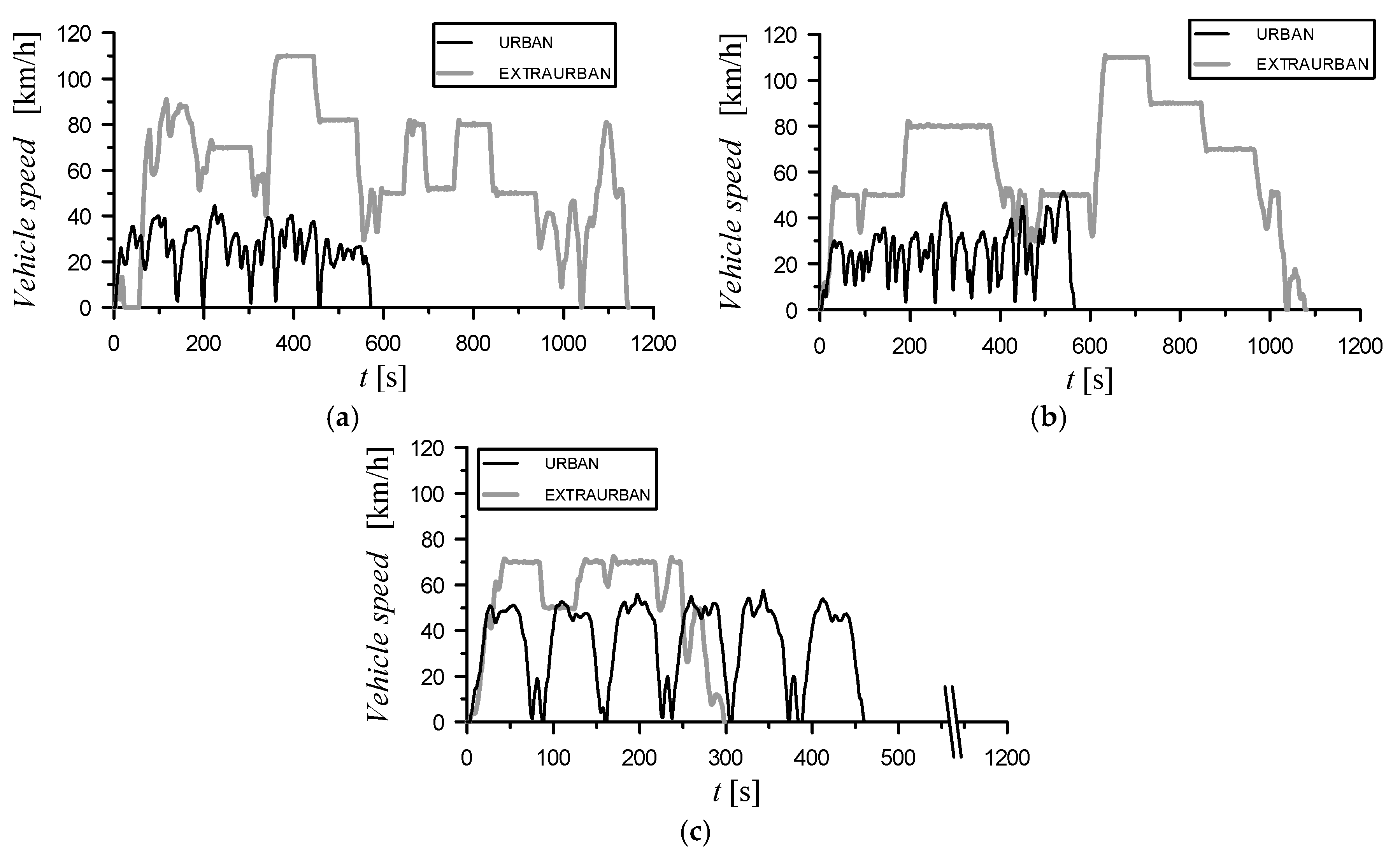
Figure 4 shows the velocity profiles followed with the vehicle during tests at different locations. In all cases, under urban-driving conditions, the vehicle was tested following random velocity profiles. However, under extra-urban driving conditions, the vehicle was tested following previously defined and repeated velocity profiles. As Figure 4 shows, the maximum vehicle velocity under extra-urban driving conditions at the highest altitude was limited to 70 km/h.

2.4. Vehicle Pre-Conditioning

Before testing each type of circuit, the vehicle was preconditioned with a regeneration process of the diesel particle filter (DPF) in order to avoid thermal effects on the exhaust system different from those of engine operation. The regeneration of the DPF was achieved by driving at high velocities. After finishing this process, the vehicle was ready for the test.

2.5. Data Sampling and Processing

The tests were carried out at an ambient temperature of around 20 °C in all locations (Valencia, Ciudad Real and Sierra Nevada). The tests were repeated 3 times for each circuit (urban or extra-urban) in order to reduce the influence of random factors and to ensure the reliability of data. In all cases, the sampling frequency for instantaneous measurements was 2 Hz. The results presented correspond to the mean values and the error bars indicate the standard deviation.

2.6. Tested Fuels

In this work, three fuels were tested: (i) a CEPSA Co. commercial diesel fuel with 5.8% (vol.) of biodiesel which was used as reference, (ii) an animal fat biodiesel fuel supplied by BDP Stock del Valles Co. (Spain), considered as a second generation biodiesel since it was made using non-food feedstock, and (iii) a Gas to Liquid (GTL) fuel obtained from natural gas by means of a Low-Temperature Fischer–Tropsch process, which was provided by SASOL Co. (South Africa). The main properties of fuels tested are presented in Table 2.

3. Methodology for Determining the Energy Recovery Potential

A complete description of the calculation methodology is presented by Agudelo et al. [29]. Instantaneous specific exergy of exhaust gases at the outlet of the DPF is determined from their instantaneous temperature, pressure and chemical composition [29]. In order to perform an exergy analysis, it is necessary to define the dead or reference state previously. For the case under study, atmospheric temperature held constant (20 °C), but atmospheric pressure takes three values, depending on the location. Therefore, there will be three dead states, one for each condition: T 0 = 20 °C, p 0 = 1013 kPa, 950 kPa and 790 kPa for Valencia, Ciudad Real and Sierra Nevada, respectively.
Total enthalpy (H) and exergy (E) of the exhaust gases at the outlet of the DPF for a trip are calculated as follows for each driving cycle (also called circuit) with a duration of tf seconds [29]:
H m , g [ J ] = 0 t f m g ˙ h g d t
E m , g [ J ] = 0 t f m g ˙ e g d t
These quantities are used to define the average exergy to energy ratio of exhaust gases at the outlet of the DPF, which is an indicator of their average energy quality throughout each cycle [28]:
δ m , g   [ % ] = E m , g H m , g × 100

4. Thermoelectric Fuel Savings Calculation

The thermoelectric generator causes additional pressure losses that the engine must overcome with extra pumping work. The pressure drop in the TEG heat exchanger is related to the internal geometry of its hot side. Power losses due to the pressure drop must be considered in TEGs as increased engine pumping work, and they can be calculated as (Equation (4))
P L = V ˙ Δ P =   m g ρ ˙ Δ p
where V ˙ is the volumetric flow and Δ P the pressure drop across the TEG heat exchanger.
The net power obtained is then calculated by subtracting these energy losses from the electrical power production (Equation (5)):
P n e t =   P P L
The electrical power output P and the pressure drop power losses P L were obtained using exhaust temperature and mass-flow rate experimental data from the vehicle and a three-dimensional CFD model of the TEG developed and validated in a previous work [24].
Normally, the electrical power needed in vehicles is provided by an alternator. The extra cost (in fuel mass flow) of producing an electric power P with the alternator of the vehicle is (Equation (6))
Δ m ˙ F , 0 = P η a l t η e n g L H V
The alternator efficiency   η a l t was equal to 50%, a typical value for belt-driven alternators [45]. The coolant inlet temperature (50 °C) and mass-flow rate (0.2 L/s) were fixed in all cases to better evaluate the changes in results that the hot source (exhaust gas from the engines) causes.
The cost of producing the same electric power P with the TEG is the cost of extra pumping work (Equation (7)):
Δ m ˙ F , T E G = P L η e n g L H V
For the same torque and engine speed (same operating point), the fuel savings of using a TEG instead of the vehicle alternator is (Equation (8))
E F M S   [ % ] = Δ m ˙ F , 0 Δ m ˙ F , T E G m ˙ F , 0   100 = Δ m F , s m F   100
where m ˙ F , 0 is the total fuel consumed by the engine to provide the effective power of the corresponding operating conditions and electric power using the alternator (baseline conditions), Δ m F , s is the fuel mass saving and m F is the total mass of fuel consumed during the driving cycle.
The mass of fuel saved by recovering energy with a TEG system can be expressed as an equivalent saving in carbon emissions. The specific emission of CO2 for each fuel (SECO2,F) is calculated from the stoichiometry of the combustion reaction. Values of this parameter are 3.16 gCO2/gF, 2.79 gCO2/gF and 3.11 gCO2/gF for diesel, biodiesel and GTL fuels, respectively. Therefore, it is possible to calculate the estimated carbon emissions savings by taking into account the total distance traveled in the driving cycle:
Δ C O 2 , S   [ g C O 2 k m ] = Δ m F , S [ g F ] × S E C O 2 , F   [ g C O 2 g F ] D c y c l e   [ k m ]
Using fuel density, ρ F , fuel mass savings can be expressed as fuel volume savings, which can be given as fuel volume per traveled distance. Therefore, the estimated fuel volume savings are calculated as
E F V S   [ L 100   k m ] = 100 × Δ m F , S / ρ F D c y c l e  

5. Results and Discussion

5.1. Exhaust Gas Characterization

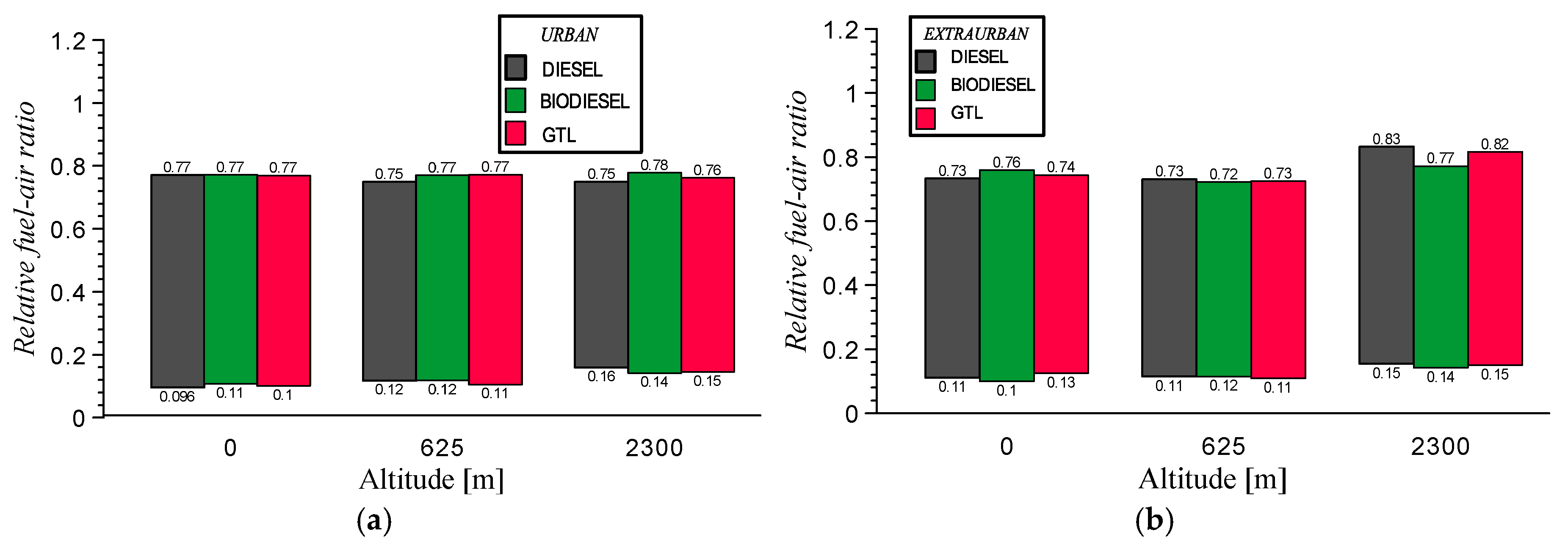
Figure 5 presents the range of variation of the relative fuel-air ratio obtained with all test fuels at the three altitudes tested. In these ranges, minimum values correspond to idle conditions, while maximum values correspond to the maximum power demanded by the engine.
For urban driving, the maximum values of the relative fuel-air ratio were similar, independently of altitude. However, a slight increase trend of minimum values with altitude was observed. This behavior can be explained by the difference in ambient pressure (measured by the own ECU pressure sensor of the vehicle). The reduction of ambient pressure is clearly affecting the EGR valve position at idle engine operation (at this operating condition the external power demanded to the engine for the vehicle movement is zero). In the case of maximum values, the effect of ambient pressure on the EGR valve closure is negligible. In this case, the power demand is clearly higher, and the EGR valve is almost closed.
The same was observed for idle conditions under extra-urban driving. However, under power demand for the vehicle movement, two facts affect the values registered of the relative fuel-air ratio (i) altitude and (ii) the positive slope of the road profile at 2300 m.
In these cases of altitude where the road slope was almost zero (0 and 625 m), the effect of ambient pressure is hindered: the EGR valve is completely closed leading to slightly lower relative fuel-air ratios as a consequence of the increase on inlet air mass flow compared to the same altitudes at urban conditions. However, at 2300 m the maximum values of the relative fuel-air ratios are clearly the highest. In this case, an additional quantity of fuel is demanded due to the slope of the road.
Regarding the effect of fuel, the highest difference is observed with biodiesel under extra-urban conditions at Sierra Nevada because the maximum value of the relative fuel-air ratio reached was significantly lower than those corresponding to diesel and GTL fuels. In a previous study, this difference was justified by the higher desired injected fuel quantity that implies more air necessary for the combustion process [4].
As Figure 6 shows, the exhaust gases are hotter on average under extra-urban conditions, which will contribute to a greater recovery potential. When these results are compared to the data corresponding to the NEDC tests presented in a previous study with the same vehicle [46], the range of the temperature variation at 625 masl is very similar between real driving conditions and extra-urban driving and for the fourth urban driving cycles. The reason for this result is that the engine was warmed-up at the start of the tests for real driving. These temperature levels present a feasible scenario for energy recovery. Although relative fuel-air ratios were similar between urban and extra-urban circuits, the absence of EGR favors higher combustion temperatures and, consequently, higher exhaust gas temperatures.
As can be observed, the lowest values of the exhaust gas temperature (corresponding to the beginning of tests) increase slightly with altitude. This increase is clearer at the upper end of the gas temperature ranges. This behavior can be explained by the closing of the EGR valve to deliver a higher amount of power as the altitude increases. Similar ranges of the exhaust gas temperature are observed for the different fuels at all altitudes.
Having exhaust gases with thermal conditions characterized by temperatures between 140 and 420 °C, makes the use of commercial thermoelectric devices with Bi2Te3 based alloys and with PbTe based alloys possible [9]. This panorama is even more promising when the vehicle works to regenerate post-treatment devices such as diesel particle filters (DPF), which may result in maximum exhaust gas temperatures of about 800 °C.

5.2. Exhaust Gas Exergy

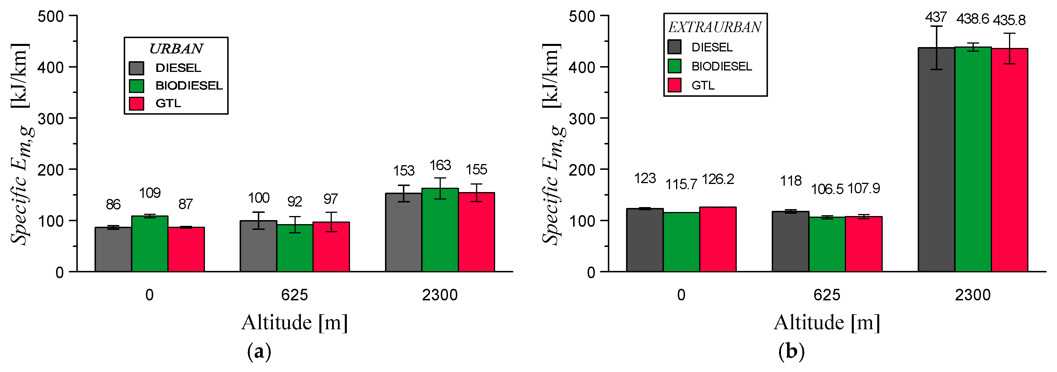
Figure 7 presents the total exergy of exhaust gases at the outlet of the DPF, obtained by using Equation (2) and the traveled distance. These values of specific exergy (kJ/km), obtained from the driving patterns followed at each altitude, represent the maximum potential of energy harvesting from exhaust gases to be converted into mechanical work or electricity. If a reversible recovery device was available, this would be the maximum theoretical energy recovered for producing useful work. The recovery potential is higher at both conditions (urban and extra-urban) for the greatest altitude, which is due to the higher gas temperatures (see Figure 6) and mass flow rates reached.
As can be seen in Figure 6, under extra-urban driving conditions, the gas temperature reached values around 400 °C at Sierra Nevada. These high values are partially due to the characteristics of this circuit (high slope) and the altitude of this location (2300 masl). The higher power demanded at these conditions (higher throttle position demand) implies these three actions: first, to close the exhaust gas recirculation (EGR) valve; second, the turbocharger geometry is varied for increasing the intake pressure, and third, the fuel mass injected is also increased. These actions are presented in detail in Reference [43].
Extra-urban driving at high altitudes results in a significantly lower fuel economy (16.1 L/100 km with diesel fuel) than for driving at lower altitudes (about 6.5 L/100 km with diesel fuel). This higher vehicle (engine) inefficiency is the main reason for the greatest recovery potential at high altitudes. Results for all fuels are similar when they are compared at the same conditions (altitude and circuit) except in the case of biodiesel at Valencia whose values of specific Em,g were the highest at the urban circuit and the lowest at the extra-urban circuit. These trends are consistent with temperatures reached with biodiesel in these circuits (see Figure 6).
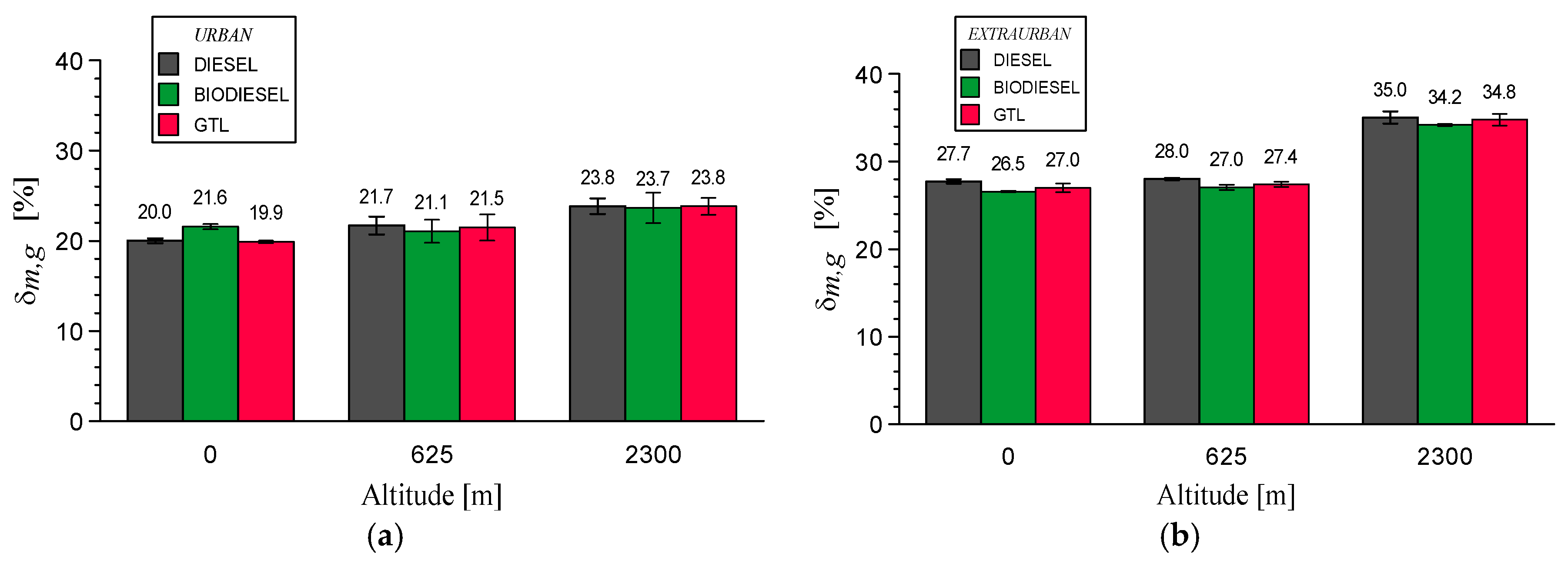
Figure 8 presents the average exergy to energy ratio of the exhaust gases at the outlet of the DPF (Equation (3)). In all cases, it remains below 35%, showing that even in the best case, it is only possible to transform about one-third of the energy of exhaust gases into useful work. This result agrees with the results from previous investigations [47]. Since exhaust gas energy recovery is focused on producing electricity or mechanical work, the results from exergy analysis are more relevant than those of energy analysis since they reveal the true potential to produce useful work. The exergy to energy ratio increases as the altitude is higher for both urban and extra-urban circuits. This behavior is caused by gas temperature ranges.

5.3. Fuel Savings

Results for estimated fuel mass savings (Equation (8)) are presented in Figure 9. Fuel savings are higher for extra-urban driving than for urban driving in all cases. This is explained by the higher vehicle speeds (see Figure 4a,b), which results in significantly higher engine loads, as can be verified by the higher temperature profiles of extra-urban driving (see Figure 6). The low velocities and loads in urban driving may not create enough of a temperature gradient in the TEG. Nevertheless, note that these are only mean values and the TEG would be active at some points in the urban cycles. The lower benefits in terms of EFMS with biodiesel are partially due to its lower heating value and, consequently, its higher fuel consumption.
Despite the higher gas temperature for extra-urban driving at 2300 masl (Figure 6), its lower driving time and higher fuel consumption result in fuel savings similar to those of the other locations at extra-urban driving. It can also be useful in terms of reduction of pollutant emissions, in particular, carbon dioxide, as shown in Figure 10.
The urban circuit shows little or no potential for thermoelectric energy recovery due to the lower exhaust temperatures. Nevertheless, under extra-urban conditions, the thermoelectric production rises to 0.23%. This low value is due to the low efficiencies of the current thermoelectric materials, but it could be helpful in the long-term use of the vehicle. In the case of the biodiesel fuel, the fuel savings are lower due to the lower exhaust temperature.
Regarding altitude, there is a significant increase in the thermoelectric production at the highest altitude, due to the increased relative fuel-air ratio. Given the relatively small altitude difference between 0 and 625 masl, there are no significant differences in fuel savings for urban or extra-urban driving on these locations.
Carbon emission reductions associated with fuel mass savings can reach 1 g/km. Nevertheless, it is necessary to have the complete picture of carbon dioxide emissions, given that the TEG systems to be used would have net carbon dioxide emissions associated with its manufacturing. A life cycle assessment of TEG systems for vehicles has shown that the conversion efficiency of such devices plays a relevant role in the life cycle carbon emissions of the whole system [18].
Finally, Figure 11 presents the estimated fuel volumetric consumption for all fuels at the two circuits tested. The notably higher consumption at the Sierra Nevada location during extra-urban conditions for all fuels, justified by the characteristic of this circuit, is remarkable. At this altitude, the circuit has a significant positive slope between its beginning and its end. When comparing the effect of fuels, biodiesel shows the highest consumption, which is lower when given in the basis of mass (g/km) because its higher density partially compensates for its lower heating value.
From these values, the estimated fuel volume savings (EFVS) were calculated (see Figure 12). Although the results are low, the use of TEG does not penalize fuel consumption. Fuel volume data are more easily related to vehicle performance and economic savings. For the range of values presented in Figure 11, using an average current fuel price of 1.34 €/L (characteristic of Spain [48]), economic savings will be up to 0.046 €/100 km (mean value at extra-urban conditions at 2300 masl). A priori, this might not be much, but it is a useful figure to determine the payback period of a feasible recovery device. In addition, the environmental benefit from reducing carbon dioxide emissions must be considered and it could also be included in the economic benefit of recovering exhaust gas energy in vehicles. From the results shown in Figure 12, the effect of altitude on EFVS is similar between 0–625 m in both circuits, urban and extra-urban. However, the benefits obtained in tests carried out in Sierra Nevada were significantly higher, especially in the extra-urban circuit. The presence of oxygen in the fuel reduces the impact of the reduced oxygen content at high altitude [4], which is one of the main justifications for the higher values of EFVS related to biodiesel fuel.

6. Conclusions

This work determined the potential for energy recovery from exhaust gases with thermoelectric generators in a passenger car. Tests were carried out on a typical light-duty diesel vehicle (2.0 L) using three fuels (diesel, gas-to-liquid, and biodiesel) at different altitudes (<20, 625 and 2300 masl) under urban and extra-urban driving conditions. The main conclusions from the results obtained are the following:
(i)
Up to 2300 masl, the expected exhaust gas temperature, downstream of the post-treatment devices (in this case, DPF), varies within the range 140–400 °C independently of the fuel tested (diesel, biodiesel and GTL fuels).
(ii)
The potential for energy recovery is always higher under extra-urban driving conditions at all altitudes tested due to the higher engine load and, consequently, higher temperatures and gas mass flow rates reached. This result is particularly important at high altitudes when the EGR valve is closed.
(iii)
Similar results were obtained between 0 and 625 masl for total exergy, exergy to energy ratio of gases, and fuel mass savings. This indicates that this altitude range, which corresponds to most European capital cities, does not have a significant effect on the potential for energy recovery.
(iv)
A total of 20–30% is the proportion of the energy of exhaust gases that could be converted into useful work in a recovery system coupled to the exhaust system of a current light-duty diesel vehicle.
(v)
Independently of the altitude, fuel mass savings can reach up to 0.2% in extra-urban driving conditions, while under urban driving conditions, the mean fuel savings are close to zero. Although these values are low, the use of TEG does not penalize fuel consumption. This result is valid for the TEG material and heat exchanger used in this work.
(vi)
The low efficiency of current commercial thermoelectric materials causes low values of recovered energy in real driving conditions.

Author Contributions

R.G.-C. and Á.R. participated doing the experimental tests and registering the raw database. R.G.-C., A.G., A.A. and P.F.-Y. worked doing the data analysis and obtaining results. O.A. defined the test plan and directed all the work. All authors participated in the writing of the manuscript.

Funding

This work was funded by three institutions: (i) the Castilla-La Mancha Government through the grant COMBALT-2, Ref. POII10-0173-0731, (ii) the Ministry of Economy and Competitiveness by the grant POWER ENE2014-57043-R and (iii) the University of Castilla-La Mancha by the financial support to the stay of Andrés Agudelo.

Acknowledgments

Authors wish to thank the Ministry of Economy and Competitiveness by the financial support provided to the project POWER ENE2014-57043-R and the University of Castilla-La Mancha by the financial support to the stay of Andrés Agudelo. Authors also wish to thank the technical support provided by NISSAN Europe Technology Centre Spain and by the vehicle supplied. Authors also wish to thank the contribution of the companies SASOL (South Africa) and Stock del Vallés (Spain) by the fuel supply.

Conflicts of Interest

Authors declare no conflict of interest.

Nomenclature

Δ m ˙ F , 0 Increase in the total fuel mass-flow to provide electric energy (alternator) (g/s)
Δ m ˙ F , T E G Increase in the total fuel mass-flow to provide electric energy (thermoelectric generator) (g/s)
Δ m F , s Fuel mass saving (g)
DcycleDistance traveled (km)
E Exergy (J)
E ˙ Exergy rate (W)
h Specific enthalpy (J/kg)
H Enthalpy - Energy (J)
L H V Lower heating value (J/kg)
m ˙ F , 0 Total fuel mass-flow rate of the engine using an alternator (baseline conditions) (g/s)
P Electric power output (W)
P L Engine pumping losses (W)
P n e t Net power output (W)
SECO2,FSpecific emissions of CO2 (g CO2/g fuel)
δ Exergy to energy ratio
ηEfficiency
altAlternator
engEngine
0 Dead state conditions, initial conditions
g Exhaust gases
L o s s Losses in the components
m Mean (time average)
sSaving

Abbreviations

DOCDiesel oxidation catalyst
DPFDiesel particle filter
EFMSEstimated fuel mass saving
EFVSEstimated fuel volume saving
EGRExhaust gas recirculation
ETGElectrical turbo-generation (or generator)
maslMeters above sea level
NEDCNew European Driving Cycle
ORCOrganic Rankine Cycle
TEGThermoelectric generator

References

  1. Directive 2009/28/EC of the European Parliament and of the Council of 23 April 2009 on the promotion of the use of energy from renewable sources. Off. J. Eur. Union 2009, 5, 2009.
  2. Wakode, V.R.; Kanase-Patil, A.B. Regression analysis and optimization of diesel engine performance for change in fuel injection pressure and compression ratio. Appl. Therm. Eng. 2017, 113, 322–333. [Google Scholar] [CrossRef]
  3. Li, X.; Zhou, H.; Zhao, L.M.; Su, L.; Xu, H.; Liu, F. Effect of split injections coupled with swirl on combustion performance in DI diesel engines. Energy Convers. Manag. 2016, 129, 180–188. [Google Scholar] [CrossRef]
  4. Ramos, Á.; García-Contreras, R.; Armas, O. Performance, combustion timing and emissions from a light duty vehicle at different altitudes fueled with animal fat biodiesel, GTL and diesel fuels. Appl. Energy 2016, 182, 507–517. [Google Scholar] [CrossRef]
  5. Guarieiro, L.L.N.; de Almeida Guerreiro, E.T.; dos Santos Amparo, K.K.; Manera, V.B.; Regis, A.C.D.; et al. Assessment of the use of oxygenated fuels on emissions and performance of a diesel engine. Microchem. J. 2014, 117, 94–99. [Google Scholar] [CrossRef]
  6. Liu, S.; Shen, L.; Bi, Y.; Lei, J. Effects of altitude and fuel oxygen content on the performance of a high pressure common rail diesel engine. Fuel 2014, 118, 243–249. [Google Scholar] [CrossRef]
  7. Battista, D.D.; Mauriello, M.; Cipollone, R. Waste heat recovery of an ORC-based power unit in a turbocharged diesel engine propelling a light duty vehicle. Appl. Energy 2015, 152, 109–120. [Google Scholar] [CrossRef]
  8. Formula One Power Unit Regulations 2014. Available online: https://www.fia.com/sites/default/files/publication/file/FIA%20F1%20Power%20Unit%20leaflet.pdf (accessed on 20 March 2019).
  9. Zheng, A.X.F.; Liu, C.X.; Yan, Y.Y.; Wang, Q. Review of thermoelectrics research—Recent developments and potentials for sustainable and renewable energy applications. Renew. Sustain. Energy Rev. 2014, 32, 486–503. [Google Scholar] [CrossRef]
  10. Wei, D.; Lu, X.; Lu, Z.; Gu, J. Performance analysis and optimization of organic Rankine cycle (ORC) for waste heat recovery. Energy Convers. Manag. 2007, 48, 1113–1119. [Google Scholar] [CrossRef]
  11. Comamala, M.; Cózar, I.R.; Massaguer, A.; Massaguer, E.; Pujol, T. Effects of Design Parameters on Fuel Economy and Output Power in an Automotive Thermoelectric Generator. Energies 2018, 11, 3274. [Google Scholar] [CrossRef]
  12. Thacher, E.F.; Helenbrook, B.T.; Karri, M.A.; Richter, C.J. Testing of an automobile exhaust thermoelectric generator in a light truck. Proc. Inst. Mech. Eng. 2007, 221, 95–107. [Google Scholar] [CrossRef]
  13. Bell, LE. Cooling, heating, generating power, and recovering waste heat with thermoelectric systems. Science 2008, 321, 1457–1461. [Google Scholar] [CrossRef]
  14. Legros, A.; Guillaume, L.; Diny, M.; Zaïdi, H.; Lemort, V. Comparison and impact of waste heat recovery technologies on passenger car fuel consumption in a normalized driving cycle. Energies 2014, 7, 5273–5290. [Google Scholar] [CrossRef]
  15. Ando Junior, O.; Calderon, N.; de Souza, S. Characterization of a thermoelectric generator (TEG) system for waste heat recovery. Energies 2018, 11, 1555. [Google Scholar] [CrossRef]
  16. Fernández-Yáñez, P.; Armas, O.; Kiwan, R.; Stefanopoulou, A.G.; Boehman, A.L. A thermoelectric generator in exhaust systems of spark-ignition and compression-ignition engines. A comparison with an electric turbo-generator. Appl. Energy 2018, 229, 80–87. [Google Scholar] [CrossRef]
  17. Shu, G.; Zhao, J.; Tian, H.; Liang, X.; Wei, H. Parametric and exergetic analysis of waste heat recovery system based on thermoelectric generator and organic rankine cycle utilizing R123. Energy 2012, 45, 806–816. [Google Scholar] [CrossRef]
  18. Kishita, Y.; Ohishi, Y.; Uwasu, M.; Kuroda, M. Evaluating the life cycle CO2 emissions and costs of thermoelectric generators for passenger automobiles: A scenario analysis. J. Clean. Prod. 2016, 126, 607–619. [Google Scholar] [CrossRef]
  19. Yu, R.; De Vaulx, C.; Aixala, L. Waste heat recovery by thermoelectricity on passenger car and heavy-duty truck diesel engine: The RENOTER project. In Diesel Powertrain Innovative Technologies for Future Emissions. France. 2012, pp. 1–8. Available online: https://www.researchgate.net/publication/295490897_Waste_heat_recovery_by_thermoelectricity_on_passenger_car_and_heavy-duty_truck_diesel_engine_the_RENOTER_project (accessed on 20 March 2019).
  20. Twaha, S.; Zhu, J.; Yan, Y.; Li, B. A comprehensive review of thermoelectric technology: Materials, applications, modelling and performance improvement. Renew. Sustain. Energy Rev. 2016, 65, 698–726. [Google Scholar] [CrossRef] [Green Version]
  21. Demir, M.E.; Dincer, I. Performance assessment of a thermoelectric generator applied to exhaust waste heat recovery. Appl. Therm. Eng. 2017, 120, 694–707. [Google Scholar] [CrossRef]
  22. Kempf, N.; Zhang, Y. Design and optimization of automotive thermoelectric generators for maximum fuel efficiency improvement. Energy Convers. Manag. 2016, 121, 224–231. [Google Scholar] [CrossRef] [Green Version]
  23. Massaguer, A.; Massaguer, E.; Comamala, M.; Pujol, T.; González, J.R.; Cárdenas, M.D.; Carbonell, D.; Bueno, A.J. A method to assess the fuel economy of automotive thermoelectric generators. Appl. Energy 2018, 222, 42–58. [Google Scholar]
  24. Fernández-Yañez, P.; Armas, O.; Capetillo, A.; Martínez-Martínez, S. Thermal analysis of a thermoelectric generator for light-duty diesel engines. Appl. Energy 2018, 226, 690–702. [Google Scholar] [CrossRef]
  25. Rakopoulos, C.D.; Giakoumis, E.G. Second-law analyses applied to internal combustion engines operation. Prog. Energy Combust. Sci. 2006, 32, 2–47. [Google Scholar] [CrossRef]
  26. Khoobbakht, G.; Akram, A.; Karimi, M.; Najafi, G. Exergy and Energy Analysis of Combustion of Blended Levels of Biodiesel, Ethanol and Diesel Fuel in a DI Diesel Engine. Appl. Therm. Eng. 2016, 99, 720–729. [Google Scholar] [CrossRef]
  27. Fernández-Yáñez, P.; Gómez, A.; García-Contreras, R.; Armas, O. Evaluating thermoelectric modules in diesel exhaust systems: Potential in urban and extra-urban driving conditions. J. Clean. Prod. 2018, 182, 1070–1079. [Google Scholar] [CrossRef]
  28. Boretti, A.A. Transient operation of internal combustion engines with Rankine waste heat recovery systems. Appl. Therm. Eng. 2012, 48, 18–23. [Google Scholar] [CrossRef]
  29. Agudelo, A.F.; García-Contreras, R.; Agudelo, J.R.; Armas, O. Potential for exhaust gas energy recovery in a diesel passenger car under European driving cycle. Appl. Energy 2016, 174, 201–212. [Google Scholar] [CrossRef]
  30. Caliskan, H.; Tat, M.E.; Hepbasli, A. Performance assessment of an internal combustion engine at varying dead (reference) state temperatures. Appl. Therm. Eng. 2009, 29, 3431–3436. [Google Scholar] [CrossRef]
  31. Perez, P.L.; Boehman, A.L. Performance of a single-cylinder diesel engine using oxygen-enriched intake air at simulated high-altitude conditions. Aerosp. Sci. Technol. 2010, 14, 83–94. [Google Scholar] [CrossRef]
  32. Agudelo, J.; Agudelo, A.; Pérez, J. Energy and exergy analysis of a light duty diesel engine operating at different altitudes. Rev. Facult. Ing. Univ. Antioq. 2009, 48, 45–54. [Google Scholar]
  33. Wang, X.; Ge, Y.; Yu, L.; Feng, X. Effects of altitude on the thermal efficiency of a heavy-duty diesel engine. Energy 2013, 59, 543–548. [Google Scholar] [CrossRef]
  34. Çakmak, A.; Bilgin, A. Exergy and energy analysis with economic aspects of a diesel engine running on biodiesel-diesel fuel blends. Int. J. Exergy 2017, 24, 151–172. [Google Scholar] [CrossRef]
  35. Paul, A.; Panua, R.; Debroy, D. An experimental study of combustion, performance, exergy and emission characteristics of a CI engine fueled by Diesel-ethanol-biodiesel blends. Energy 2017, 141, 839–852. [Google Scholar] [CrossRef]
  36. López, I.; Quintana, C.E.; Ruiz, J.J.; Cruz-Peragón, F.; Dorado, M.P. Effect of the use of olive–pomace oil biodiesel/diesel fuel blends in a compression ignition engine: Preliminary exergy analysis. Energy Convers. Manag. 2014, 25, 227–233. [Google Scholar] [CrossRef]
  37. Nabi, M.N.; Rasul, M.G. Influence of second generation biodiesel on engine performance, emissions, energy and exergy parameters. Energy Convers. Manag. 2018, 169, 326–333. [Google Scholar] [CrossRef]
  38. Aghbashlo, M.; Tabatabaei, M.; Khalife, E.; Shojaei, T.R.; Dadak, A. Exergoeconomic analysis of a DI diesel engine fueled with diesel/biodiesel (B5) emulsions containing aqueous nano cerium oxide. Energy 2018, 149, 967–978. [Google Scholar] [CrossRef]
  39. Benjumea, P.; Agudelo, J.; Agudelo, A. Effect of altitude and palm oil biodiesel fuelling on the performance and combustion characteristics of a HSDI diesel engine. Fuel 2009, 88, 725–731. [Google Scholar] [CrossRef]
  40. Tat, M.E. Cetane number effect on the energetic and exergetic efficiency of a diesel engine fuelled with biodiesel. Fuel Process. Technol. 2011, 92, 1311–1321. [Google Scholar] [CrossRef]
  41. Ramos, A.; Muñoz, J.; Armas, O.; Andrés, F. NOx emissions from diesel light duty vehicle tested under NEDC and real-world driving conditions. Transp. Res. D Transp. Environ. 2018, 63, 37–48. [Google Scholar] [CrossRef]
  42. Fairbanks, J. Automotive Thermoelectric Generators and HVAC. In 2013 Annual Merit Review and Peer Evaluation Meeting; DOE Vehicle Technologies Office: Washington, DC, USA, 2013. [Google Scholar]
  43. Armas, O.; García-Contreras, R.; Ramos, A. On-line thermodynamic diagnosis of diesel combustion process with paraffinic fuels in a vehicle tested under NEDC. J. Clean. Prod. 2016, 138, 94–102. [Google Scholar] [CrossRef]
  44. Armas, O.; García-Contreras, R.; Ramos, A. Emissions of Light Duty Vehicle Tested under Urban and Extraurban Real-World Driving Conditions with Diesel, Animal Fat Biodiesel and GTL fuels. SAE Tech. Paper 2013. [Google Scholar] [CrossRef]
  45. Karri, M.A.; Thacher, E.F.; Helenbrook, B.T. Exhaust energy conversion by thermoelectric generator: Two case studies. Energy Convers. Manag. 2011, 52, 1596–1611. [Google Scholar] [CrossRef]
  46. Armas, O.; García-Contreras, R.; Ramos, A.; López, A.F. Impact of animal fat biodiesel, GTL and HVO fuel son combustion, performance and pollutant emissions of a light-duty diesel vehicle tested under the NEDC. J. Energy Eng.-ASCE 2015, 141, C4014009. [Google Scholar] [CrossRef]
  47. Al-Najem, N.; Diab, J. Energy-exergy analysis of a diesel engine. Heat Recover. Syst. CHP 1992, 12, 525–529. [Google Scholar] [CrossRef]
  48. Diesel Prices in Europe, l. Global Petrol Prices. Available online: http://www.globalpetrolprices.com/diesel_prices/Europe/ (accessed on 14 February 2019).
Figure 1. Sketch of the experimental equipment.
Energies 12 01105 g001
Figure 2. Prototype of the thermoelectric generator used for this study.
Energies 12 01105 g002
Figure 3. (a) Urban Sierra Nevada, (b) Extra-urban Sierra Nevada, (c) Urban Ciudad Real, (d) Extra-urban Ciudad Real, (e) Urban Valencia, (f) Extra-urban Valencia.
Energies 12 01105 g003
Figure 4. Examples of the velocity profiles followed in the tests at the different locations: (a) Valencia, (b) Ciudad Real and (c) Sierra Nevada.
Energies 12 01105 g004
Figure 5. Operating range of the engine relative fuel-air ratio: (a) Urban driving conditions, (b) Extra-urban driving conditions.
Energies 12 01105 g005
Figure 6. Measured exhaust gas temperature range at the outlet of the diesel particle filter (DPF): (a) Urban driving conditions, (b) Extra-urban driving conditions.
Energies 12 01105 g006
Figure 7. Specific exergy of exhaust gases: (a) Urban driving conditions, (b) Extra-urban driving conditions.
Energies 12 01105 g007
Figure 8. Average ratio of the exergy to energy of gases: (a) Urban driving conditions, (b) Extra-urban driving conditions.
Energies 12 01105 g008
Figure 9. Estimated fuel mass savings: (a) Urban driving conditions, (b) Extra-urban driving conditions.
Energies 12 01105 g009
Figure 10. Estimated carbon dioxide emissions savings: (a) Urban driving conditions, (b) Extra-urban driving conditions.
Energies 12 01105 g010
Figure 11. Volumetric fuel consumption: (a) Urban driving conditions, (b) Extra-urban driving conditions.
Energies 12 01105 g011
Figure 12. Estimated fuel volume savings: (a) Urban driving conditions, (b) Extra-urban driving conditions.
Energies 12 01105 g012
Table 1. Main vehicle and engine characteristics.
Vehicle
Effective frontal area (Cd × A)0.83 m2
Weight (including devices and operators)2025 kg
Engine
Cylinders4
Displacement1994 cm3
Bore84 mm
Stroke90 mm
Power max.110 kW at 4000 min−1
Torque max.323 Nm at 2000 min−1
Transmission
TypeManual, 6 gears
1st gear ratio3.727
2nd gear ratio2.043
3rd gear ratio1.322
4th gear ratio0.947
5th gear ratio0.723
6th gear ratio0.596
Differential ratio4.266
Tyres
Code215/65R16
Injection system
Injection pressure1600 bar (Maximum)
Number of nozzle holes5
Table 2. The fuel properties.
PropertiesDIESELBIODIESELGTL
Molecular FormulaC14.62H26.87O0.08C18.41H37.23O2C16.89H35.77
Molecular Weight (g/mol)203.7290.7238.9
H/C Ratio1.842.022.12
Stoichiometric Fuel/Air Ratio1/14.451/12.701/14.95
C (% w/w)86.1476.1484.82
H (% w/w)13.212.8315.18
O (% w/w)0.6611.030
Density at 15 °C (kg/m3) (EN ISO 12185)845877774
Viscosity at 40 °C (cSt) (EN ISO 3104)2.514.032.34
Lower Mass Heating Value (MJ/Kg)42.4336.8344.03
Lower Volumetric Heating Value (MJ/L)35.8532.2934.08
CFPP (°C) (EN 116)−163−7
Derived Cetane Number54.265.689.2