Abstract
Data-driven intelligent transportation systems (D2ITSs) have drawn significant attention lately. This work investigates a novel multi-agent-based data-driven distributed adaptive cooperative control (MA-DD-DACC) method for multi-direction queuing strength balance with changeable cycle in urban traffic signal timing. Compared with the conventional signal control strategies, the proposed MA-DD-DACC method combined with an online parameter learning law can be applied for traffic signal control in a distributed manner by merely utilizing the collected I/O traffic queueing length data and network topology of multi-direction signal controllers at a single intersection. A Lyapunov-based stability analysis shows that the proposed approach guarantees uniform ultimate boundedness of the distributed consensus coordinated errors of queuing strength. The numerical and experimental comparison simulations are performed on a VISSIM-VB-MATLAB joint simulation platform to verify the effectiveness of the proposed approach.
1. Introduction
Conventional technology-driven ITS is on the brink of a revolution in the age of big data. Data-driven intelligent transportation system (D2ITS) is trending to become a more powerful way of improving traffic efficiency, enhancing traffic security, saving energy and providing more possibilities for different stakeholders [1].
In urban transportation, it is costly and unsustainable to add additional infrastructure to accommodate the increased number of vehicles due to the limited road resources. A more socially feasible option is the optimization of traffic signal timing in a data-driven and learning-based manner. Since urban traffic systems are becoming more and more complex, establishing an exact mechanistic model of road networks or even an intersection is difficult or impossible due to its higher order, strong nonlinearities, non-stationary nature and complicated structures. Furthermore, acquiring the traffic data regarding vehicle count, queue, occupancy and flow has become much easier, and a huge amount of online/offline data is collected every day from auxiliary heterogeneous traffic sensors, e.g., inductive-loop detectors, microwave detectors, video surveillance and RFID. Thereby the spatial–temporal relationship between traffic data should be considered when performing a D2ITS.
One promising way is to develop data-driven control (D2C) [2] for traffic signal timing. In the last decade, research on D2C has received much more attention, such as model free adaptive control (MFAC) [3,4], iterative learning control (ILC) [5], lazy learning control (LL) [6], virtual reference feedback tuning (VRFT) [7], and iterative feedback tuning (IFT) [8]. Without using the explicit information from the mathematical model, D2C is designed by utilizing I/O data directly obtained from the controlled system or data processing [9]. From an application point of view, D2C of urban traffic systems will play a key role in D2ITS due to the availability, reliability and integrity of traffic data and is closer to real-life traffic signal control problems than many model-based approaches [10].
A renowned fixed timing approach is the so-called Webster’s signal plan, which is used to calculate the green time and the cycle using offline traffic data [11]. While some adaptive mechanisms, such as SCOOT [12], SCAT [13] and GLIDE [14], have been successfully implemented in real urban traffic systems due to the merits of dynamic tuning of signal timing. In recent years, some D2C strategies were investigated addressing the performance optimization of complex dynamic traffic systems. Adaptive dynamic programming (ADP) and reinforcement learning (RL) methods [15] have emerged in solving Markov decision processes with uncertain conditions. In [16], for solving the problem of streetcar bunching, the multiple reinforcement learning agents were developed for a series of successive signalized intersections. A Q-learning algorithm was introduced for optimal control of heavily congested traffic across in [17]. To achieve the global optimization of urban traffic control, Salkham et al. [18] studied a collaborative reinforcement learning approach.
Although ADP-based learning control could achieve good results, the shortcomings of slow convergence rate, poor stability, curse of dimensionality and difficulty in selecting reward functions may extremely hinder its application. Therefore, some real-time, rapid, recursive D2C designs by using MFAC or ILC techniques have also been proposed for freeway traffic control systems with high nonlinearity and repetitive operations [19,20,21]. Unfortunately, those protocols are still deficient for realizing traffic signal D2C.
Moreover, some prominent features, such as multi-functionality, multi-sourcing and multi-users, have recently become a positive force for traffic control changes. Therefore, as a rapidly developing field of artificial intelligence, multi-agent-based urban traffic distributed control strategies have attracted significant importance because they provide a highly flexible and modular structure [22]. To avoid solving complex traffic control problem as a whole, they offer distributed protocols by dividing the original problem into many sub-problems to get an optimal solution, in particular, for a large-scale traffic network system.
By using a hybrid neural network, a new simultaneous perturbation stochastic approximation- based neural network (SPSA-NN) [23] is developed for each intersection. The total mean delay and the total mean stoppage time of each vehicle has been substantially reduced. However, for each traffic pattern, a large number of training samples is needed for the implementation of a SPSA-NN model. The number of decision-making modules and the slow convergence rate would reduce the system performance. Another distributed multi-agent-based control method is Type-2 fuzzy with dynamic reasoning (T2DR) [24]. A weighted type-2 fuzzy inference engine and separate belief model are proposed to calculate the weights for input. The problem in this case is that T2DR strongly depends on the accuracy of the trained belief model’s limiting the parameter learning capability. Similar to the T2DR, geometric fuzzy multi-agent system (GFMAS) is addressed by modifying the belief model to reduce the number of training samples needed, thereby geometric defuzzification is used to further reduce the computational requirements [25]. A large number of samples is however still needed to ensure better accuracy. Also, an unconstrained fixed sequence clearing strategy (UNCFSCS) [26] is adopted recently for all completely empty vehicles in a fixed sequence from the point of multi-phase coordination. It is very restricted in application due to the unsaturated intersections condition. Therefore, a sample independent distributed multi-agent-based control under constraints is indispensable as a supplement.
It was pointed out by Choy et al. [27] that a three layered hierarchical multi-agent architecture, intersection controller agents (ICA), zone controller agents (ZCA) and regional controller agents (RCA), is appropriate to analyze the real-time traffic signal control. In terms of ICA, the traffic data of queuing length, vehicle arrival rate and saturation flow rate collected from different sensors placed in the lanes is taken into account as each ICA input. Based on the obtained data, green time for a specific phase or direction in progress and the cooperation factor of multi-agents in intersections are computed to adjust the signaling and traffic routing pattern for alleviating traffic jams, reducing the environmental pollution and the consumption of energy.
In this paper, we focus on the lowest layer ICA signal timing problem. A novel multi-agent-based data-driven distributed adaptive corporative control (MA-DD-DACC) is investigated for multi-direction queuing strength balance with changeable cycles at single intersections in urban traffic signal control. The main contributions of this work can be summarized as follows:
- (1)
- A rapid and recursive distributed adaptive corporative control strategy with online parameter learning law is proposed by using the queuing length and the network topology of multi-direction signal controllers at single intersection;
- (2)
- Traffic signal direction-sequence control is adopted here to avoid phase conflicts;
- (3)
- A flexible changeable cycle signal timing strategy is analyzed satisfying maximum and minimum green time constraints;
- (4)
- Both the undersaturation and supersaturation traffic flow conditions can be handled by the proposed MA-DD-DACC without distinction.
The rest of this paper is distributed as follows: Section 2 briefly introduces the traditional store-and-forward model and multi-directional queuing strength model, respectively. Section 3 introduces the data-driven cooperative control technology for queuing strength balance in a single intersection network. Section 4 shows the Lyapunov-based stability analysis of MA-DD-DACC. Section 5 gives the simulation results obtained by a joint programming method, showing the effectiveness of the algorithm. Finally, Section 6 summarizes the paper.
2. Preliminaries
2.1. Store-and-Forward Model
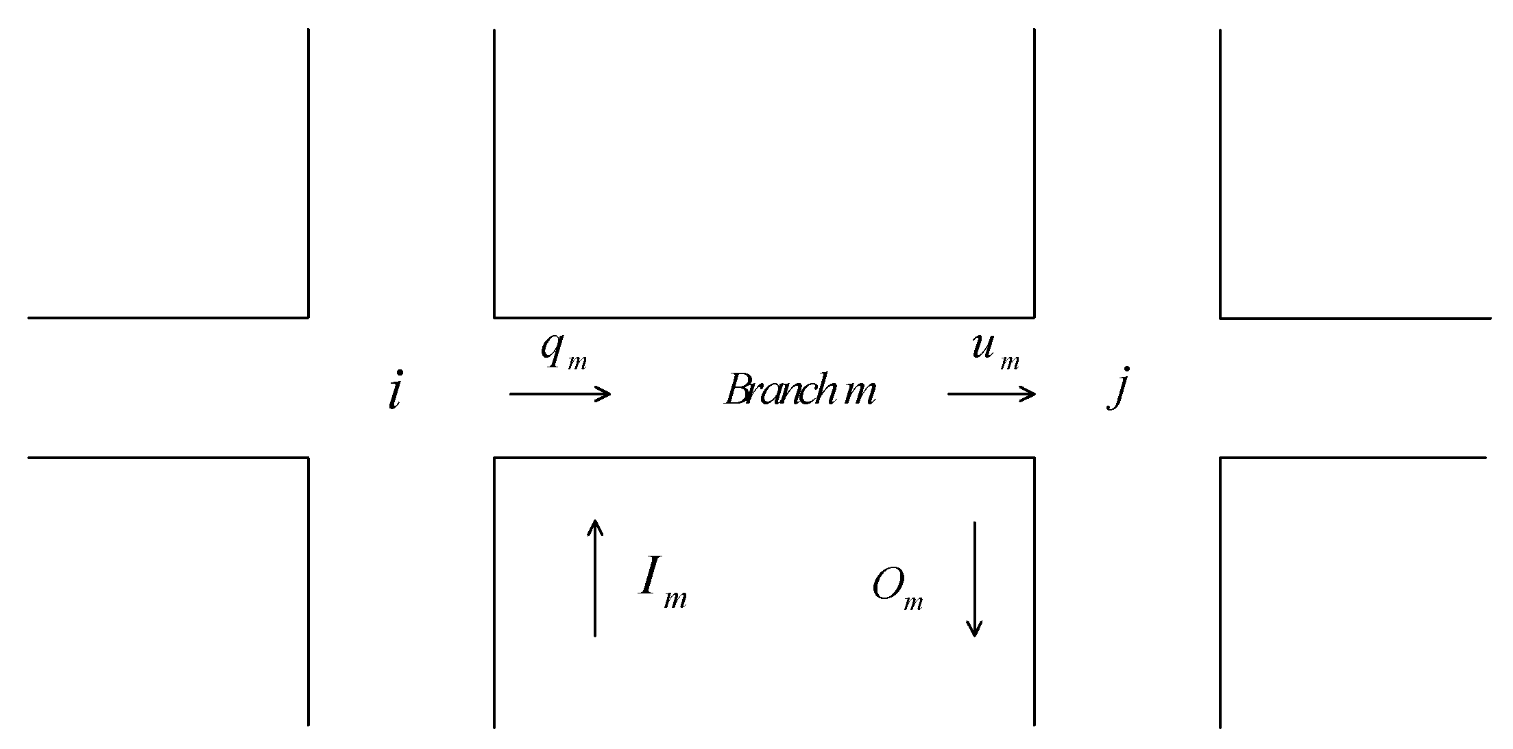
As shown in Figure 1 branch connects intersection and , and vehicles move from intersection to intersection .
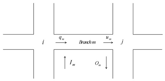
Figure 1.
Traffic flow in a store-and-forward model.
The traffic flow dynamic of branch is expressed as follows:
where T is known as the sampling interval, denotes the number of vehicles on branch , and are defined as the input and output of branch in , respectively. and represent traffic flow demand and dissipation of branch , respectively.
Dissipative flow satisfies the following equation:
where is defined as the dissipation rate which is a known constant.
Input flow satisfies the following equation:
where is the steering ratio of vehicles on branch entering branch through intersection j. Assuming that the traffic demand of branch is sufficient, the output flow satisfies:
where is the signal cycle. denotes the green time and satisfies:
If the sampling interval T equals the cycle , equals the mean of traffic flow in the whole cycle, the actual traffic flow is or zero in the green or red period, so as long as the traffic demand is sufficient, there is a continuous and stable traffic flow in the road network.
By substituting Equations (2)–(5) into (1), it can be obtained that:
The state equation of arbitrary dimension, topological structure and traffic flow characteristics can be rewritten by using Equation (6):
where the state vector denotes the number of vehicles on each road in the road network during the k-th sampling period, and are stationary matrices reflecting road network characteristics. Denote , . is the green time vector of all intersections in the road network, is the corresponding initial green time nominal vector, and are traffic demand and initial steady flow, respectively.
2.2. Multi-Directional Queuing Strength Model with Changeable Cycle
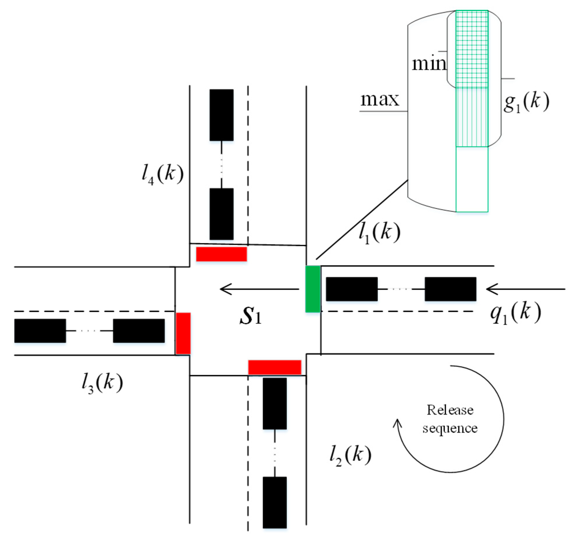
The multi-directional queuing strength balance problem for traffic signal timing is shown in Figure 2. Based on the store-and-forward model, the multi-directional queuing length model with changeable cycle at single intersection is as follows:
where and . denotes the i-th direction of the intersection. denotes four directions; denotes the k-th cycle which is changeable; denotes the number of queuing vehicles of the k-th cycle in the i-direction; denotes the vehicle arrival rate of the k-th cycle in the i-th direction, denotes the saturation flow rate in the i-th direction; denotes the green time of the k-th cycle in the i-th direction.
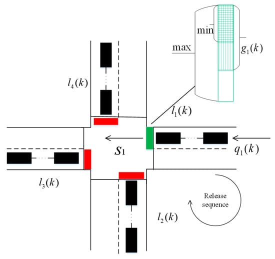
Figure 2.
Multi-direction queuing strength balance with changeable cycle at a single intersection.
The green time and traffic signal cycle in all directions at intersections satisfy the following constraints:
where denotes the total lost time at the intersection.
The queuing strength of an entrance line at an intersection is defined as the ratio of the queuing length of the entrance line (the number of queuing vehicles) to the length of its link (the storage capacity of vehicles) is as follows:
where denotes the queuing strength of the i-th entrance line in the k-th cycle, denotes the storage capacity of vehicles of the i-th entrance line.
Therefore, multi-directional queuing strength model is given below:
The degree of saturation of the k-th cycle in the i-th entrance line of the intersection is defined as:
According to the definition of the degree of saturation, traffic state of the k-th cycle in the i-th direction can be judged as follows: (1) indicates undersaturation; (2) indicates critical saturation; (3) indicates supersaturation.
When traffic state of the intersection is undersaturation, i.e., , according to Equation (11), decreases continuously and may eventually be reduced to a negative value. Due to the non-negative characteristics of traffic system variables, the undersaturation state in store-and-forward model will lose its physical and control significance at this time. In the traditional store-and-forward model analysis, only the traffic signal timing under the supersaturated traffic condition is usually considered. If more green time is allocated in an undersaturated situation, there will be a waste of green time. Therefore, only less green time is needed to ensure capacity. However, since most traffic signal control systems are fixed cycle control and meet the constraints of maximum and minimum green time, signal timing is often limited and cannot be perfectly compatible with undersaturated, critical saturated and supersaturated conditions. In order to avoid wasting green time, it is necessary introduce time-varying control signal cycle leading to new green time constraints to ensure the queue strength satisfying . Therefore, the green time and signal cycle under constraints become:
Accordingly, the constrained multi-direction queuing strength model (11) with changeable cycle at single intersection would be rewritten as:
The proposed queueing strength model (15) can formulate three traffic flow conditions: undersaturation, critical saturation and supersaturation, simultaneously.
3. Problem Formulation and Controller Design
3.1. Cooperative Control Problem Describtion
When the queuing strength balance is achieved at single intersection, the desired queueing strength can be expressed as:
where is the average queue strength of four directions in k-th cycle; and are the average increase and decrease of queuing strength in the k-th signal cycle.
Considering each direction queuing strength as an agent, distributed consensus coordinated error of queuing strength in the i-th direction of one intersection is given below:
where denotes the adjacency matrix in network topology of signal controllers at single intersection, denotes the connection coefficient between the -direction queuing strength and the desired one. Moreover, define the in-degree of the ICA as and in-degree matrix as . Then Laplacian matrix in network topology of multi-direction signal controller graph is .
The unknown nonlinear parameterized functions and satisfy the relation:
and consequently, satisfy the following inequality conditions by incorporating the parameter separation technique [28]:
where denotes an unknown function related to vehicle arrival rate , denotes a known function related to signal cycle , and meets . According to Equation (18), we choose .
The global multi-direction and desired queuing strength as well as consensus coordinated error can be described as follows, respectively:
where , , , , , , , , are defined as N-Dimensional vector composed of element 1, and denotes a diagonal matrix.
Moreover, the difference dynamics of global consensus coordinated error is as follows:
Remark 1.
is a centralized global coordinated error of queueing strength. We assume that at least one directional signal controller can obtain centralized global information . The global coordinated errors e, rather than centralized global information is more suitable for Lyapunov-based distributed data-driven adaptive controller design.
Remark 2.
Considering that the digraph of each direction queueing strength at single intersection is strongly connected and at least one signal controller can communicate with others. Considering that the digraph contains a spanning tree for all directions at single intersection, that is to say, there is at least one , thenmatrix is an irreducible principal diagonalmatrix and is a nonsingular matrix. All the poles ofmatrix are distributed in the right half plane.
Remark 3.
Define that the eigenvalue of a matrix can be expressed as. Thenandrepresent the maximum and minimum eigenvalues, respectively. Frobenius norm is defined as, where. represents the trace of a matrix. Frobenius inner product of two matrices is defined as .
For the convenience of the following discussion, we first discuss the three properties of saturation functions and two lemmas in multi-agent systems in terms of queuing strength model.
Lemma 1.
If a digraph is strongly connected and , then L of digraphs is irreducible and there is at least one positive diagonal elementin matrix, then matrixis a nonsingular-matrix. Define:
wheredenotes the minimum eigenvalue of matrix, when , if and only if the queue strength in all directions reaches balance.
Lemma 2.
If the Laplacian matrix L of digraphs is irreducible and there is at least one positive diagonal elementin matrix, then matrixis a nonsingular-matrix. Define:
then , the definition of matrix is:
then .
For , satisfying , then
Property 1
[5].
Property 2
[5]. For , there are
Property 3
[29].
where .
3.2. Data-Driven Distributed Adaptive Cooperative Control Design
Given the following standard definitions of multi-direction queueing strength balance for distributed cooperative control problem.
Definition 1.
The global consensus coordinated error
is uniformly ultimately bounded (UUB). If there exists a compact set , so that , there exists a boundary and a time , which are independent of , then and hold.
Definition 2.
Given the desired queueing strength model (16), whose state is uniformly ultimately bounded under coordination. If there exists a compact set, so that, there exists a boundaryand a time, which are independent of, thenandhold.
Considering the queuing strength model (15), the following data-driven queuing strength cooperative control strategy for multi-agent single intersection is constructed as follows:
where represents an arbitrary control signal designed by Lyapunov technology later. The global cooperative control strategy can be written as follows:
where denotes a learning gain, .
Theorem 1.
Considering the multi-agent based queuing strength system (15) and (16) at single intersection, digraph in network topology of multi-direction signal controllers is strongly connected, and there is at least one . According to the distributed consensus coordinated error (17), the distributed adaptive cooperative control term is selected as follows:
where denotes the error learning gain.
The data-driven distributed adaptive cooperative control strategy for signal timing at single intersection is designed as follows:
where denotes the cooperative control gain, , and the parameter learning law is designed as follows:
where . denotes parameter learning gain;
The control and parameter learning gains satisfy the following conditions:
where , are positive definite matrices defined in Lemma 2.
Then the distributed consensus coordinated error of queueing strength of all directions is uniformly ultimately bounded (UUB) and converges to the desired queuing strength at single intersection. The upper bound of consensus coordinated error can be reduced by increasing the error learning gain .
Remark 4.
It is worth noting that the proposed queuing strength balance control method is almost model-free. The traffic model parameters, such as the saturation flow rate, the vehicle arrival rate in model (8) are not used both in the distributed adaptive cooperative control (34) and the parameter learning law (35). Only the queueing length of output data and network topology L and B of multi-direction signal controllers at signal intersection are used here to adjust the green time of input data. Especially, network topology information is easily obtained from adjacent relationship of traffic infrastructures and irrelevant to the real-traffic flow model. Therefore, the proposed MA-DD-DACC is data-driven.
4. Stability Analysis
Proof of Theorem 1.
Define a Lyapunov function candidate as follows:
where is a diagonal matrix and .
Difference of (39):
where:
Equation (41) equals:
where .
According to (19), one has:
where .
Based on Equations (32), (33) and (45), the first term at right-hand of (44) satisfies:
where , .
Substituting (46) into (44):
Equation (42) can be rewritten as:
Given the parameter learning law as follows:
with global form:
It can be easily derived that
where is the parameter learning gain.
Then we have:
Equation (43) can be further described as:
where .
Combining Equations (52) and (53):
Rearranging terms in (54):
According to (19) again, one has:
and:
where .
The third term at the right-hand of (55) becomes:
Then Equation (55) is derived:
By using , , (59) is:
which could be rewritten as:
If is a positive definite matrix, and:
then .
Based on (39), we have:
then:
Since:
where , , and then
It can be obtained that:
which leads to Equation (62).
In Equation (61), we define the matrix as follows:
where , , , .
Firstly, select the learning gain satisfying:
such that .
Then the characteristic polynomial of matrix is given as:
we obtain all the eigenvalues as:
Let , then:
Now the third eigenvalue is:
Select an appropriate , such that:
We have:
and error and parameter learning gains satisfy:
As a result, 𝔃(k) is UUB [30]. □
5. Simulation
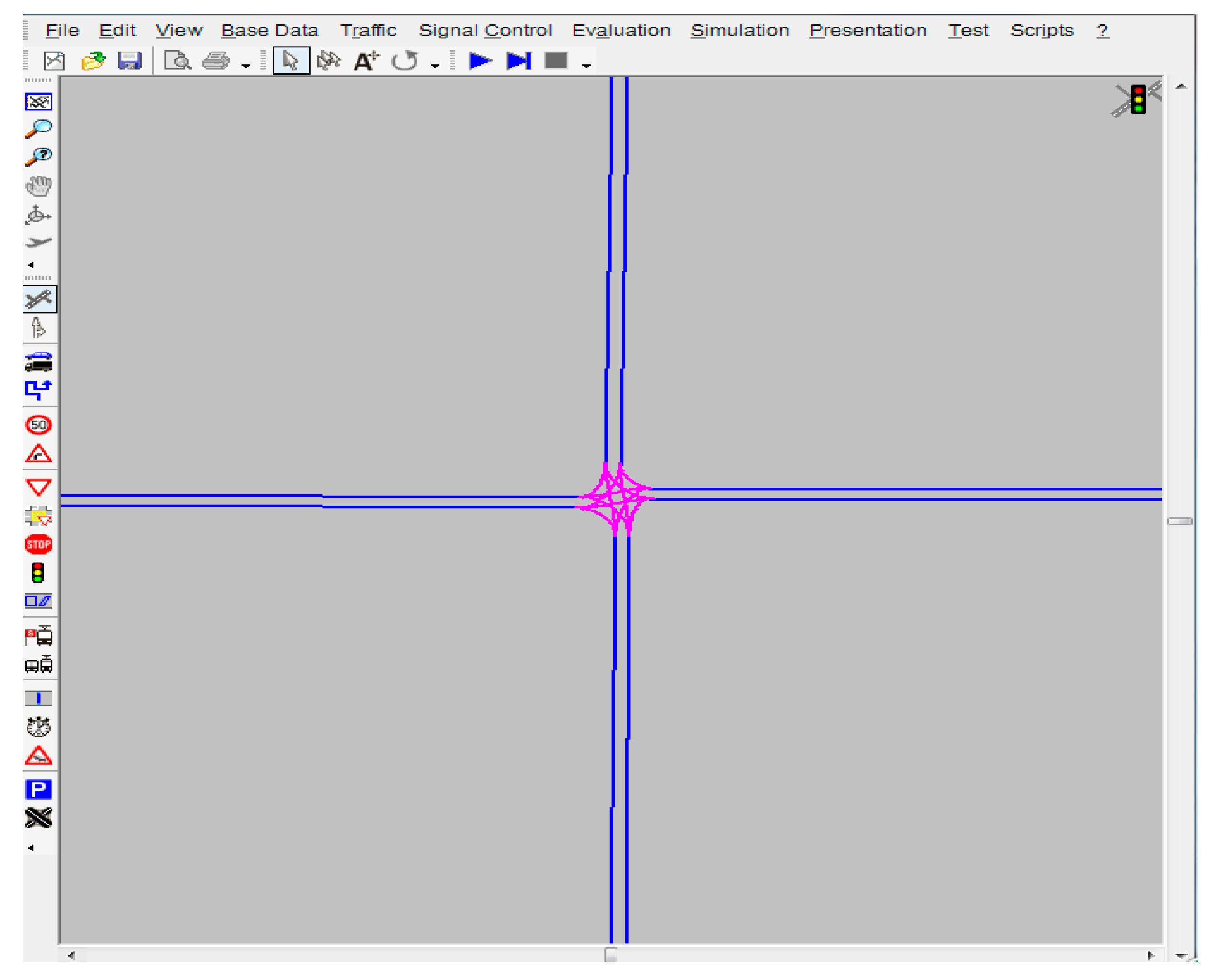
In this paper, a VISSIM-VB-MATLAB joint simulation platform is used to build a more realistic experiment. VISSIM is a professional traffic simulation software that simulates all modes of traffic and analyses their interactions. It consists of a traffic simulator and a signal state generator, which exchange detector data and signal state information through an interface. It can not only generate visualized traffic conditions online, but also output various realistic and statistical data offline, such as travel time, queue length, etc. The simulation data obtained by VISSIM is transferred into MATLAB through VB. In MATLAB, the MA-DD-DACC signal timing algorithm is used to realize the cooperative control of queue strength in four directions at single intersection. A single intersection is build by using the traffic evaluation module provided by VISSIM to output traffic evaluation data as shown in Figure 3.
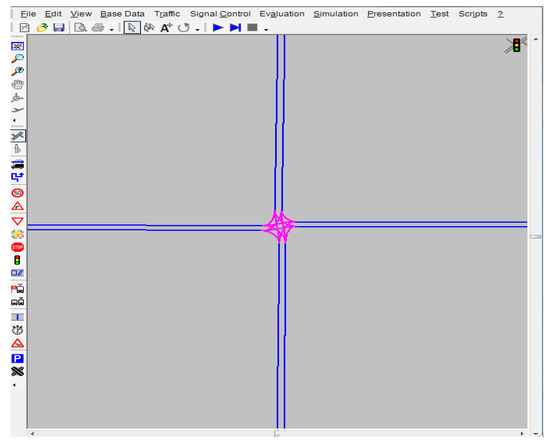
Figure 3.
Single intersection traffic modeling in VISSIM.
Using multi-directional queuing strength model with changeable cycle at intersection (15), the simulation is conducted. The initial parameters are shown in Table 1.

Table 1.
Simulation parameter table of queuing strength cooperative control at single intersection.
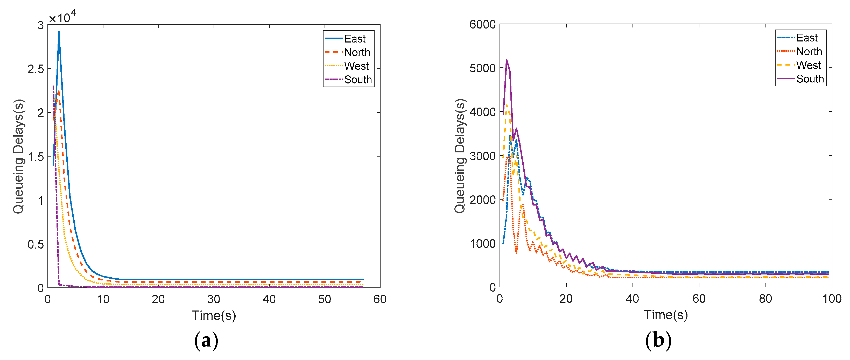
Two experiments are carried out. The first one uses the UNCFSCS [26] which is designed to release vehicles in fixed sequence at unsaturated intersections and to keep all phases completely empty. The second one adopts the MA-DD-DACC signal timing strategies presented in this paper. The total queuing delays in all directions will be recorded at the end of each cycle in the simulation running process, as shown in Figure 4. It is not difficult to find out that the queuing delays of all directions in UNCFSCS decreases eventually to zero and to keep all phases completely empty under the premise that undersaturation. While the proposed cooperative control scheme can adjust the cycle and green ratio adaptively for different traffic conditions, undersaturation, saturation and supersaturation, respectively. It should be noted that the total delays in UNCFSCS is almost six times that in MA-DD-DACC.
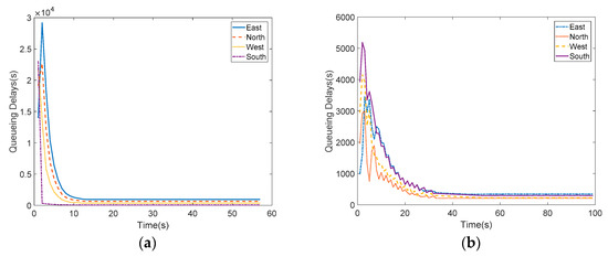
Figure 4.
(a) Queuing delays in UNCFSCS; (b) Queuing delays in MA-DD-DACC.
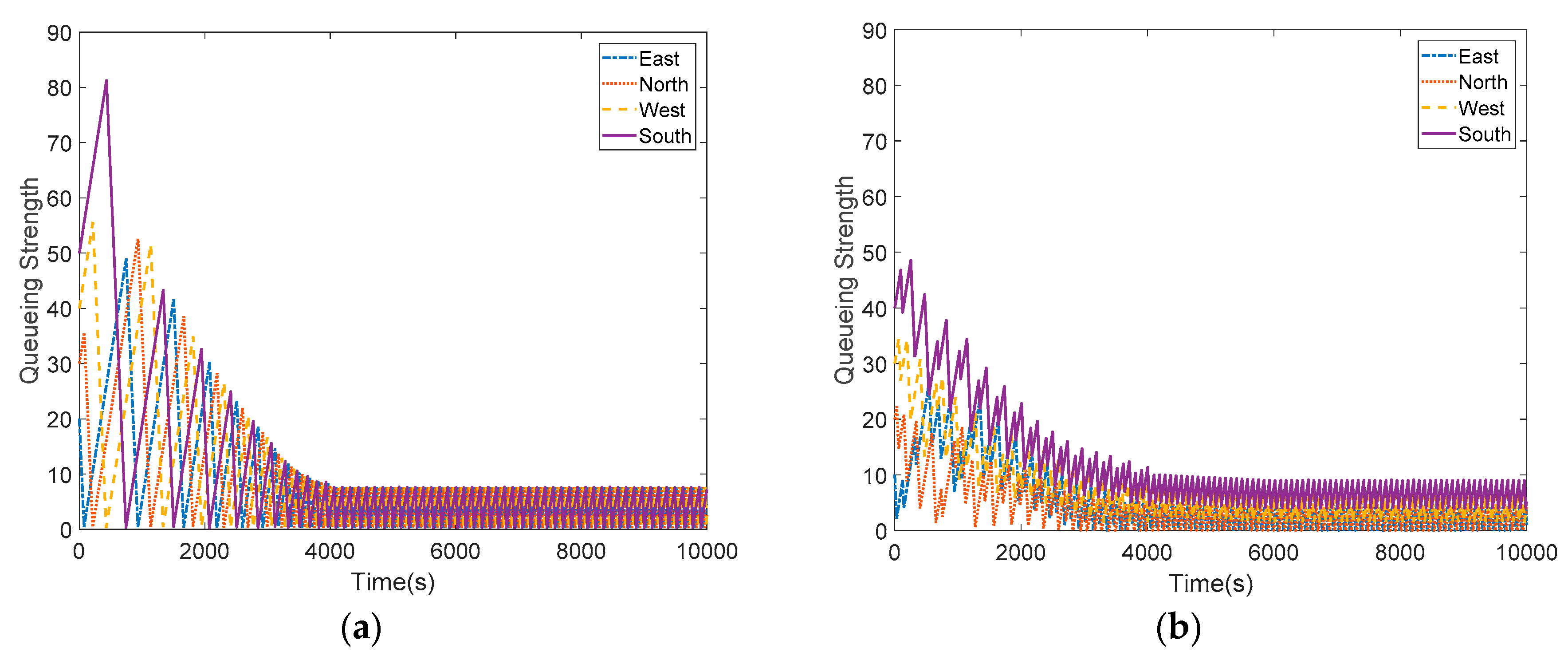
From Figure 5, the queueing strength of south direction in UNCFSCS is more than 80. However, the queueing strength of all directions in MA-DD-DACC is only less than 50. By calculation, the queueing strength mean value of four directions in MA-DD-DACC has dropped from 25 to 10 during 2190 s. While, the queueing strength mean value in UNCFSCS has dropped from 35 to 10 during 2731 s. It is obvious that the queueing strength balance is achieved which implies the proposed scheme has the merit of high convergence rate and low energy consumption as displayed.
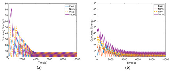
Figure 5.
(a) Queuing Strength in UNCFSCS; (b) Queuing Strength in MA-DD-DACC.
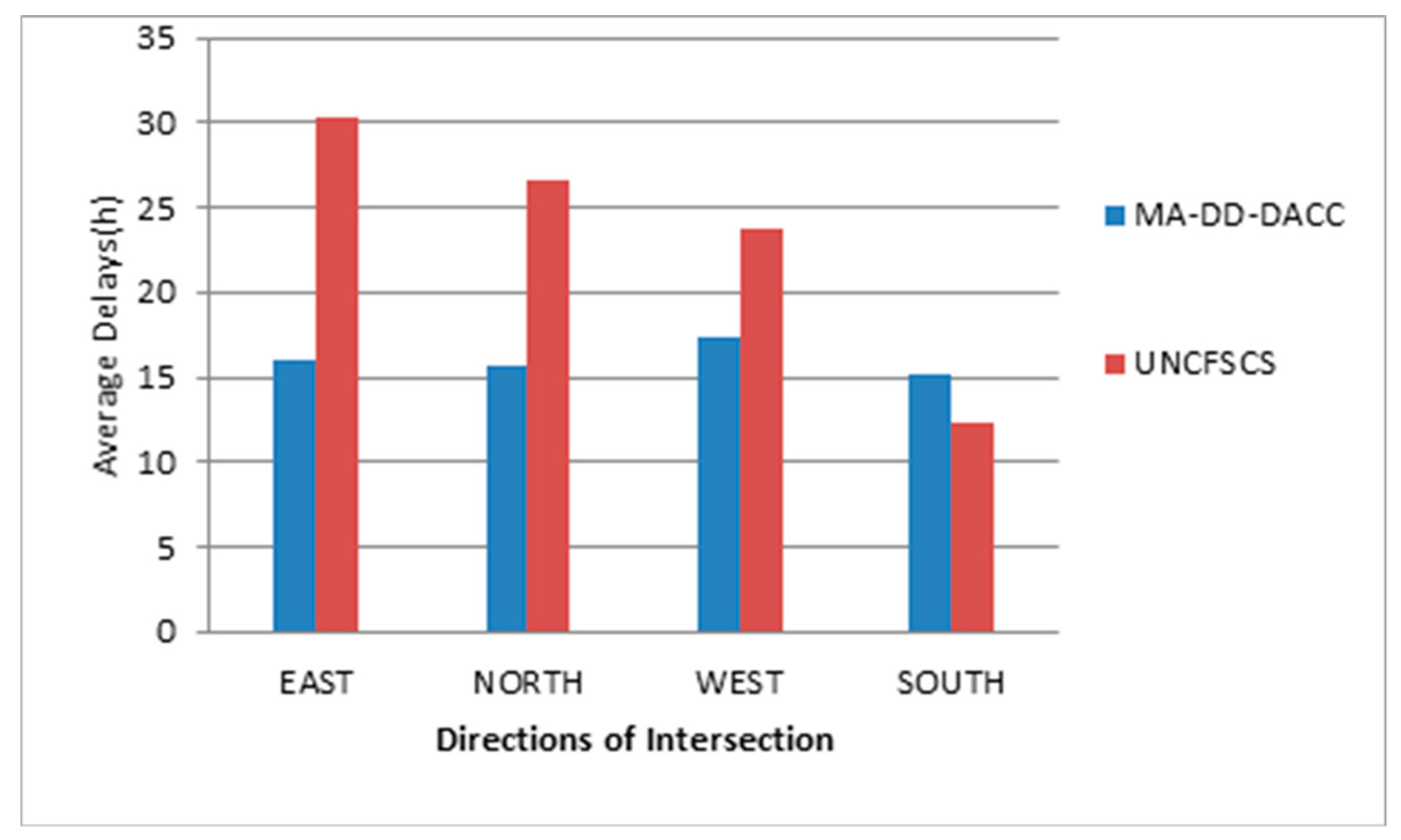
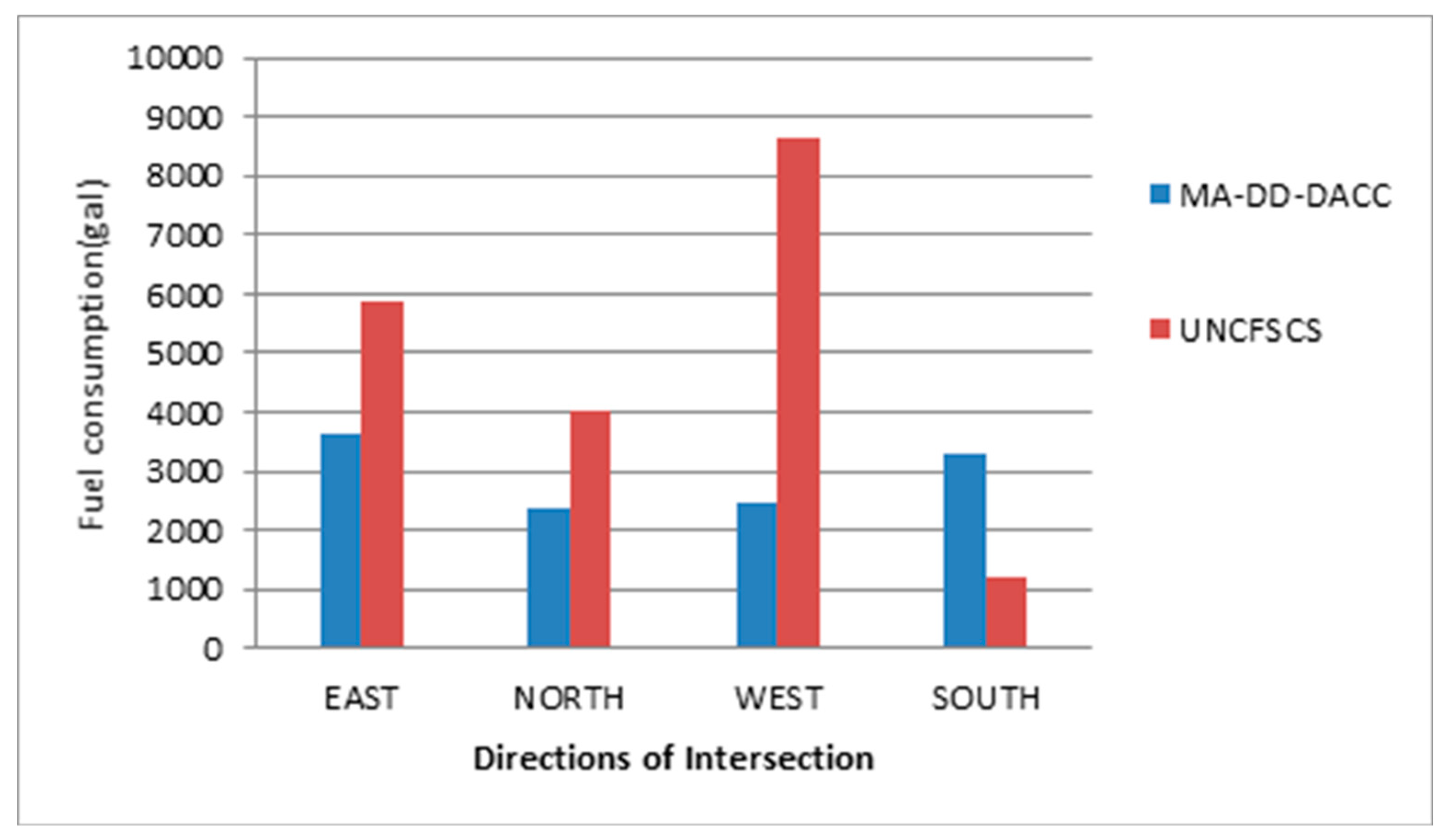
The VISSIM delay evaluation index is obtained from two simulations. It can be found that green time of each direction could be effectively adjusted by using the MA-DD-DACC such that the average vehicle delay is balanced. The performance in average delays of our proposed control is much better than that of the UNCFSCS control, as shown in Figure 6. Furthermore, the fuel consumption of MA-DD-DACC is less than that of the UNCFSCS as displayed in Figure 7. The experimental results verify the validity of the proposed MA-DD-DACC.
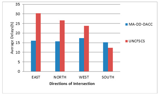
Figure 6.
Average delay comparison between MA-DD-DACC and the UNCFSCS control.
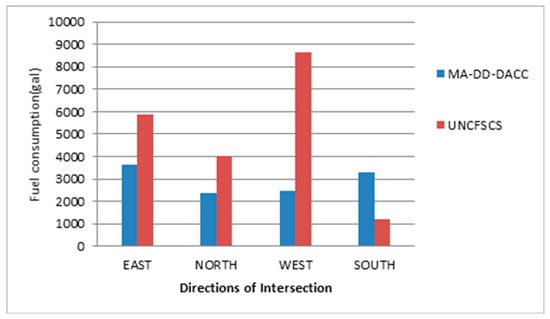
Figure 7.
Fuel consumption comparison between MA-DD-DACC and the UNCFSCS control.
6. Conclusions
This work proposed a novel MA-DD-DACC method to deal with urban traffic signal timing problem concerning phase conflict, green time constraints, changeable cycle, and network topology of multi-direction signal controllers, which achieved a fairly good performance for queuing strength balance under different kind of traffic conditions, as shown in a VISSIM-VB-MATLAB joint simulation platform. Although much future research needs to be done, it can be expected that data-driven corporative control methodology in a distributed manner for urban traffic multi-agent systems will provide a powerful tool for realizing D2ITS with the goal of reducing traffic congestion and energy consumption.
Author Contributions
Conceptualization, H.J. and H.Z.; methodology, H.J. and Z.H.; software, H.Z. and H.J.; validation, H.Z., L.F.; formal analysis, L.F. and X.L.; investigation, H.Z. and X.L.; resources, Z.H.; writing—original draft preparation, H.J. and L.F.; writing—review and editing, H.J. and L.F.; visualization, X.L. and L.F.; supervision, Z.H. and X.L.; project administration, H.J.; funding acquisition, H.Z. and Z.H.
Funding
This work was funded by the North China University of Technology Scientific Research Foundation, the National Natural Science Foundation of China (No. 61803036), the Scientific Research Common Program of Beijing Municipal Commission of Education (Grant No: KM201911232015),the Supplementary and Supportive Project for Teachers at Beijing Information Science and Technology University (2018–2020) under Grant 5029011103(5111911129), and the Service Ability Construction of Science and Technology Innovation - Construction of High-end Disciplines (PXM2019_014212_000020).
Conflicts of Interest
The authors declare no conflict of interest.
References
- Zhang, J.; Wang, F.Y.; Wang, K.; Lin, W.H.; Xu, X.; Chen, C. Data-Driven Intelligent Transportation Systems: A Survey. IEEE Trans. Intell. Transp. Syst. 2011, 12, 1624–1639. [Google Scholar] [CrossRef]
- Hou, Z.S.; Jin, S.T. Model Free Adaptive Control: Theory and Applications; CRC Press: Boca Raton, FL, USA, 2013. [Google Scholar]
- Xu, D.; Jiang, B.; Shi, P. A novel model-free adaptive control design for multivariable industrial processes. IEEE Trans. Ind. Electron. 2014, 61, 6391–6398. [Google Scholar] [CrossRef]
- Hou, Z.S.; Huang, W. The model-free learning adaptive control of a class of SISO nonlinear systems. In Proceedings of the 1997 American Control Conference, Albuquerque, NM, USA, 6 June 1997; Volume 1, pp. 343–344. [Google Scholar]
- Xu, J.X.; Tan, Y.; Lee, T.H. Iterative learning control design based on composite energy function with input saturation. Automatica 2004, 40, 1371–1377. [Google Scholar] [CrossRef]
- Hou, Z.S.; Liu, S.D.; Tian, T.T. Lazy-learning-based data-driven model-free adaptive predictive control for a class of discrete-time nonlinear systems. IEEE Trans. Neural Netw. Learn. Syst. 2017, 28, 1914–1928. [Google Scholar] [CrossRef] [PubMed]
- Sala, A. Integrating virtual reference feedback tuning into a unified closed-loop identification framework. Automatica 2007, 43, 178–183. [Google Scholar] [CrossRef]
- Hjalmarsson, H. From experiment design to closed-loop control. Automatica 2005, 41, 393–438. [Google Scholar] [CrossRef]
- Hou, Z.; Chi, R.; Gao, H. An overview of dynamic-linearization-based data-driven control and applications. IEEE Trans. Ind. Electron. 2017, 64, 4076–4090. [Google Scholar] [CrossRef]
- Markovsky, I. A missing data approach to data-driven filtering and control. IEEE Trans. Autom. Control 2017, 62, 1972–1978. [Google Scholar] [CrossRef]
- Webster, F.V. Traffic Signal Settings. Road Research Paper No. 39; Her Majesty’s Stationary Office: London, UK, 1958. [Google Scholar]
- Robertson, D.I.; Bretherton, R.D. Optimizing networks of traffic signals in real time—The scoot method. IEEE Trans. Veh. Technol. 1991, 40, 11–15. [Google Scholar] [CrossRef]
- Sims, A.G.; Dobinson, K.W. The Sydney Coordinated Adaptive Traffic (SCAT) system philosophy and benefits. IEEE Trans. Veh. Technol. 1980, 29, 130–137. [Google Scholar] [CrossRef]
- Keong, C.K. The GLIDE system—Singapore’s urban traffic control system. Transp. Rev. 1993, 13, 295–305. [Google Scholar] [CrossRef]
- Wang, F.; Zhang, H.; Liu, D. Adaptive dynamic programming: An introduction. IEEE Comput. Intell. Mag. 2009, 4, 39–47. [Google Scholar] [CrossRef]
- Ling, K.; Shalaby, A.S. A reinforcement learning approach to streetcar bunching control. J. Intell. Transp. Syst. Technol. Plan. Oper. 2005, 9, 59–68. [Google Scholar] [CrossRef]
- Abdulhai, B.; Pringle, R.; Karakoulas, G.J. Reinforcement learning for the true adaptive traffic signal control. J. Transp. Eng. 2003, 129, 278–285. [Google Scholar] [CrossRef]
- Salkham, A.; Cunningham, R.; Garg, A.; Cahill, V. A collaborative reinforcement learning approach to urban traffic control optimization. In Proceedings of the 2008 IEEE/WIC/ACM International Conference on Web Intelligence and Intelligent Agent Technology, Sydney, Australia, 9–12 December 2009; Volume 2, pp. 560–566. [Google Scholar]
- Hou, Z.S.; Xu, J.X.; Yan, J.W. An iterative learning approach for density control of freeway traffic flow via ramp metering. Transp. Res. C Emerg. Technol. 2008, 16, 71–97. [Google Scholar] [CrossRef]
- Hou, Z.S.; Xu, J.X.; Zhong, H.W. Freeway traffic control using iterative learning control based ramp metering and speed signaling. IEEE Trans. Veh. Technol. 2007, 56, 466–477. [Google Scholar] [CrossRef]
- Cheng, Z.; Hou, Z.; Jin, S. MFAC-based balance control for freeway and auxiliary road system with multi-intersections. In Proceedings of the 2015 10th Asian Control Conference (ASCC), Kota Kinabalu, Malaysia, 31 May–3 June 2015; pp. 1–6. [Google Scholar]
- Balaji, P.G.; Srinivasan, D. Multi-agent system in urban traffic signal control. IEEE Comput. Intell. Mag. 2010, 5, 43–51. [Google Scholar] [CrossRef]
- Choy, M.C.; Srinivasan, D.; Cheu, R.L. Neural networks for continuous online learning and control. IEEE Trans. Neural Netw. 2006, 17, 1511–1531. [Google Scholar] [CrossRef]
- Gokulan, B.P.; Srinivasan, D. Distributed multi-agent type-2 fuzzy architecture for urban traffic signal control. In Proceedings of the IEEE International Conference on Fuzzy Systems, Jeju Island, South Korea, 20–24 August 2009; pp. 1624–1632. [Google Scholar]
- Coupland, S.; John, R. New geometric inference techniques for type-2 fuzzy sets. Int. J. Approx. Reason. 2008, 49, 198–211. [Google Scholar] [CrossRef]
- He, Z.H.; Chen, Y.Z.; Shi, J.J.; Han, X.G.; Wu, X. Steady-state control for signalized intersections modeled as switched server system. In Proceedings of the 2013 American Control Conference, Washington, DC, USA, 17–19 June 2013; pp. 842–847. [Google Scholar]
- Choy, M.C.; Srinivasan, D.; Cheu, R.L. Cooperative, hybrid agent architecture for real-time traffic signal control. IEEE Trans. Syst. Man Cybern. A 2003, 33, 597–607. [Google Scholar] [CrossRef]
- Lin, W.; Qian, C.J. Adaptive control of nonlinearly parameterized systems: A nonsmooth feedback framework. IEEE Trans. Autom. Control 2002, 47, 757–774. [Google Scholar] [CrossRef]
- Sun, M.X.; Ge, S.S. Adaptive repetitive control for a class of nonlinearly parameterized systems. IEEE Trans. Autom. Control 2006, 51, 1684–1688. [Google Scholar] [CrossRef]
- Ji, H.H.; Lewis, F.L.; Hou, Z.S.; Mikulski, D. Distributed information-weighted Kalman consensus filter for sensor networks. Automatica 2017, 77, 18–30. [Google Scholar] [CrossRef]
© 2019 by the authors. Licensee MDPI, Basel, Switzerland. This article is an open access article distributed under the terms and conditions of the Creative Commons Attribution (CC BY) license (http://creativecommons.org/licenses/by/4.0/).

