Abstract
A fast terminal sliding mode control is proposed in this paper for improving the dynamic performance and robustness of a permanent magnet in-wheel motor system driven by a voltage source inverter. Firstly, a fast terminal sliding mode approaching law was designed to accelerate the approaching rate of the control system. Then, a torque load observer was designed to compensate for disturbances and uncertainties. Finally, fuzzy rules were designed to suppress the chattering phenomenon. Simulation and experimental results demonstrated that the fast terminal sliding mode control strategy presented better response speed than the conventional sliding mode control strategy. It had better dynamic performance and anti-interference and effectively reduced the chattering phenomenon in the control process.
1. Introduction
With the increasingly prominent issues of resource shortages and environmental pollution, energy-saving and environmentally friendly hybrid electric vehicles (HEVs) are proving to be the optimal choice for the future vehicle industry. HEVs have been rapidly booming in recent years due to their low energy consumption, lesser environmental impact, stable performance, and other merits [1,2]. Unlike in the traditional automotive drive structure, HEVs can be propelled by using in-wheel motors. This drive method has the outstanding advantages of being space-saving, highly efficient, simple in structure, and allowing the independent control of torque [3,4]. These traits will make contributions to the prospective development of HEVs.
Permanent magnet synchronous motors (PMSMs) have recently typically been used in aerospace applications, marine applications, and industrial applications because of their advantages of having high power, small size, high power density, fast response speed, and low vibration [5,6,7]. These advantages have made PMSMs become the ideal choice for in-wheel motors. A permanent magnet in-wheel motor (PMIWM) can be seated in the small space of the wheel of HEVs [8,9]. The performance of PMIWMs is sensitive to uncertain external factors such as temperature, vibration, magnetic saturation [10,11,12,13] and affects the comfort and safety of a vehicle. Therefore, the research on the control system of PMIWMs should take the external factors into consideration. The properties of PMIWMs are also linked to the internal control strategy, which influences the response speed and is the main factor affecting the dynamic performance of PMIWMs [14,15]. A proportional integral derivative (PID) is widely used in the speed and current control of PMIWMs, though it is difficult to determine optimal parameters for PID control [16,17,18], as this requires a balance between overshooting and rapidity of the whole control system.
Due to its deficiencies, the PID control is currently not in a position to meet the control accuracy and stability of PMIWM that is required [19]. Many novel control strategies have been proposed to resolve the decoupling of nonlinear systems like PMIWMs, such as direct torque control (DTC), field-oriented control (FOC), differential geometry control (DGC), variable-voltage and variable-frequency control (VVVFC), adaptive control, neural network control (NNC), fuzzy control, genetic algorithms, and sliding mode control (SMC). DTC is achieved using the space vector method, which allows direct control of the stator flux linkage and electromagnetic torque [20,21], though DTC has defects such as flux ripple and a dead-time effect. FOC strategies can allow control of motor torque by measuring and controlling the stator current vector [22,23], which is an ideal solution for the decoupling of nonlinear systems. However, FOC has low control accuracy. VVVFC is a convenient control strategy but it has the problem of insufficient torque when the speed is very low [24]. Differential geometry control can be applied to control nonlinear systems [25], though this control strategy requires the establishment of an accurate mathematical model of the control system. Adaptive control can make adjustments accounting for external disturbance [26,27], though this strategy is unable to realize ideal control performance at the beginning of its use because of the lack of a disturbance value. NNC is a novel branch of intelligent control which is useful in solving the control problem of complex, nonlinear, decoupling and uncertain systems [28,29]. Fuzzy control can simplify dynamic systems to achieve control, but the fuzzy rules mainly come from experience and knowledge of experts [30,31]. SMC has the traits of rapidity and strong anti-jamming, does not require the building of a precise mathematical model, and is insensitive to fluctuations of parameters [32].
Although the above strategies can effectively improve the control efficiency and accuracy of PMIWM systems, difficulties still exist in making a balance between response speed and robustness. Therefore, the issue of how to increase the start-up speed as well as graduate the stability of PWIWM has become crucial. This issue is intended to be solved in this paper. In [33], we presented a fuzzy sliding mode control (FSMC) strategy to improve the robustness of PMSMs through the use of a fuzzy controller. Because PMIWMs are more sensitive to external disturbances and need more ideal control accuracy, the approaching rate designed in [33] is not suitable for PMIWMs, so this paper proposes a novel approaching rate to replace the one formerly used]. Because PMIWMs which are installed in HEVs may be disturbed by variable load, this study designed a torque disturbance observer to detect load torque in real time to compensate for the torque disturbance. Additionally, the fuzzy rules designed in this paper are based on [33] but they are applied to reduce the chattering phenomenon in PMIWM systems instead of PMSMs. Simulation models verified that the fuzzy rules proposed in this paper can realize more stable control than FSMC.
This paper proposes a fast terminal sliding mode control (FTSMC) strategy in combination with a torque disturbance observer in order to control the speed of PMIWMs, and its major contributions are as follows:
- A novel FTSMC strategy is proposed to realize the rapidity and enhance the robustness of the control system.
- A torque disturbance observer is designed to compensate for the external torque, which improves the control accuracy of the system.
- Fuzzy rules are presented to overcome the chattering phenomenon of the FTSMC, which improves the dynamic performance of the system.
The rest of this paper is organized as follows: In Section 2, the PWIWM model is established, and some assumptions are made in order to simplify the mathematical model. In Section 3, the FTSMC method is presented in detail, the disturbance observer is designed, and the fuzzy rules are devised for FTSMC. Mathematics simulation and experiments are carried out, and the results are analyzed in Section 4. Section 5 presents the conclusions of this paper.
2. Mathematical Model of PMIWMs Fed by a Three-Phase Voltage Source Inverter (VSI)
This section establishes a simplified mathematical model for PMIWMs fed by a three-phase voltage source inverter (VSI). The motion equation of PWIWMs will be designed in order to determine the accurate mathematical model.
2.1. Mathematical Model of PMIWMs
On the premise of fewer influences on control accuracy, a simplified mathematical models can be established under the following assumptions [34]: (1) the magnetic circuit is unsaturated; (2) porcelain and eddy current loss are ignored; (3) there is no damping winding on the rotor; (4) the distribution of the magnetic field air gap is a sine wave; (5) the permanent magnets of PMIWMs are surface-mounted. On the above assumptions, the mathematical model of PMIWM can be obtained with Equation (1) [35]:
where and are the current of the d–q axis, respectively, is the self-inductance, , and represent the inductance of the d and q axes, respectively, is the stator resistance, and are the voltages of the d and q axes, respectively, is the permanent magnet flux linkage of the motor, is the rotating angular velocity of the PWIWM.
The motion equation of PWIWMs can be stated as:
where is the torque of the PMIWM, is the load torque, is the moment of inertia. The PMIWMs torque equation can be stated as follows:
where is the number of the magnetic pole. The d-axis magnetic inductance and the q-axis magnetic inductance of the motor are equal in surface-mounted PMIWMs. Equation (3) can be simplified as:
2.2. PMIWM Control System Fed by Three-Phase VSI
The diagram of PMIWMs fed by a VSI is shown in Figure 1, and the voltages in a three-phase stationary coordinate abc system are given as follows:
where , , and are the voltages in the three-phase stationary-coordinate abc system, respectively, is the DC bus voltage of the power unit and is the upper power switch state of one leg, when the upper power switch is on or off, as shown in Figure 1. The layout of the voltage space vectors of the VSI is shown in Figure 2 [36].
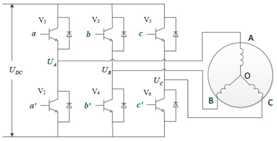
Figure 1.
Upper power switch state.
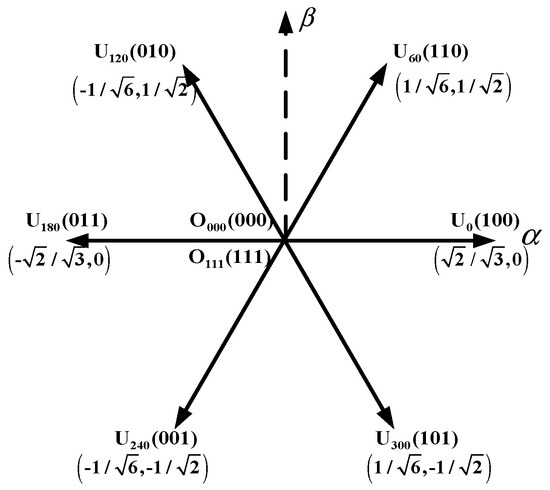
Figure 2.
Voltage space vectors of a voltage source inverter (VSI).
In order to simply the mathematical model, state variables from the abc static system can be converted to an static system using the Clark transformation and the static system can be converted to a dq rotating system using the Park transformation [37]:
where is the angular position.
3. Novel Fuzzy FTSMC Strategy Based on a Load Torque Observer for the PMIWM System
This section proposes an FTSMC algorithm based on a load torque observer in order to control the speed of the PMIWM system. Fuzzy rules are designed to reduce the chattering phenomenon of the system.
3.1. FTSMC Algorithm for Controlling the System
By combining (2) and (4), the dynamic mathematical model of the PMIWMs can be stated as follows [38]:
denoting the state parameters as follows:
where and are the state parameters, is the given speed, and is the real speed. Equation (9) can be differentiated as follows:
denoting the control input as , .
Because PMIWMs are a high-order single-input–single-output (SISO) nonlinear system, the recursive equation of the PMIWM can be stated as follows:
where , are smooth functions of the domain in , , … are state errors of the sliding mode.
Because PMIWMs can easily be interfered with by external and internal disturbances, the conventional index approaching rate is not suitable for the control system. FTSMC is a novel approaching rate which has fast approaching speed and response speed, according to [39]. The novel FTSMC variable is defined as:
where ,, , and are the sliding mode approaching parameters, , > 0, , and are positive odd numbers ( > ). The global FTSMC law is stated as:
The time of the system state reaching the sliding surface along with can be obtained as follows:
By setting , , , and , the system can converge to equilibrium state in a limited time .
According to a study [40], the Lyapunov function is denoted as follows:
The differentiation of is:
Because and are positive odd numbers, is a positive even number, and as , > 0, , the nonlinear system is stable.
Considering that PMIWM is a second-order SISO nonlinear control system, the state parameters of the PMIWM system are stated as:
According to the design of the fast terminal sliding mode surface shown in (11), the full expression of FTSMC can be stated as follows:
where , are the sliding mode approaching parameters. In this paper, the optimal parameters are selected according to [41], and the FTSMC design parameters , , , , , and are selected.
3.2. Design of the Load Torque Observer
From Equation (18), we can see that the FTSMC speed controller designed in this paper has load torque . In the actual control process, will change due to the disturbance of external loads, and is a dynamic parameter which is difficult to measure. To solve the above problems, a load torque observer was designed to detect the load torque in real time [42,43]. The observed value was denoted as and replaced in (18), thus the full expression of FTSMC became:
From (10), the extension equation of PMIWMs can be obtained as follows:
On the basis of Equation (20), the extended sliding mode load torque observer was established by taking and as observing objects. The extended sliding mode observer equation was obtained as follows:
where , is the sliding mode gain, is the observation value of speed, and is the feedback gain.
Combining (20) and (21), the equation of sliding mode observation error can be obtained as:
where is the observation error of speed, is the observation error of torque, denoting the sliding mode as .
3.3. Design of the Fuzzy Controller
Because PMIWMs are a complex control system with strong coupling and nonlinearity, a chattering phenomenon must exist in their actual control through the FTSMC strategy. The chattering phenomenon will affect the control accuracy of the control system to a certain extent, but with the elimination of chattering, the anti-jamming ability and robustness of the control system will also decrease. Some measures should therefore be taken to reduce chattering without affecting the dynamic performance of the control system. This section designs a fuzzy controller in order to solve the problem of chattering by controlling the sliding mode approaching parameter in real time.
As shown in (16), differentiation of can be changed as:
where is denoted as switching gain, and is the main cause of the chattering phenomenon. In order to reduce the chattering phenomenon, fuzzy rules have been proposed to adjust in real time.
The existence condition of the sliding mode is , and the system would remain on the sliding mode surface when reaching it. As is shown in (23), can guarantee the approaching speed of the system, while its value should meet the existence conditions . The fuzzy rules can be denoted as follows:
- , then should increase
- , then should decrease
- , then should decrease
- , then should decrease
According the fuzzy rules above, a fuzzy control system can be designed. In this system, and are denoted as fuzzy input, and is denoted as fuzzy output. The fuzzy set of the system’s input/output is defined in Table 1, and the input/output of the fuzzy system is shown in Figure 3.

Table 1.
Fuzzy set of the system’s input/output. NB: large negative, NM: middle negative, ZO: zero, PM: middle positive, PB: large positive.
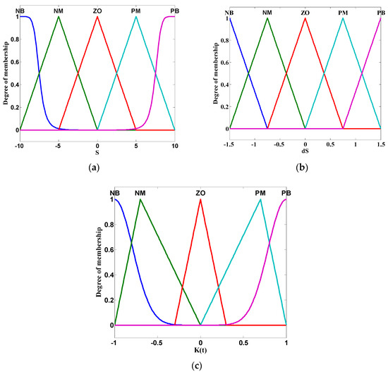
Figure 3.
The input/output of the fuzzy system. (a) input , (b) input , (c) output .
Using a fuzzy controller to adjust the upper bound of in the control system in real time is another contribution of this paper. can be calculated through the integral method:
where are the proportional parameters, and replaces in (19). The full expression of FTSMC can obtained as:
The control block diagram of the FTSMC system using the proposed fuzzy rules is presented in Figure 4 [35].
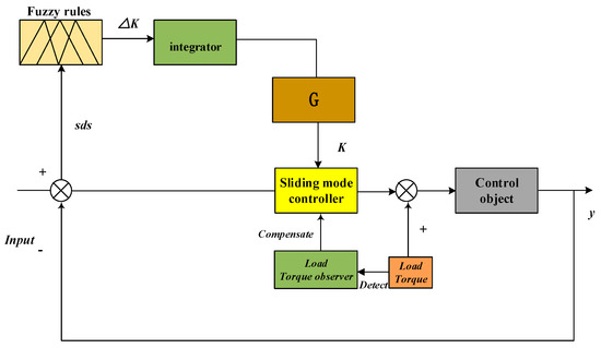
Figure 4.
Control block diagram of the fast terminal sliding mode control (FTSMC) system based on fuzzy rules.
4. Simulation and Experimentation
This section shows numerous simulations and experiments, and the specific parameters of the PWIWM are shown in Table 2.
Table 2.
Parameters of the permanent magnet in-wheel motor (PMIWM).
A MATLAB/Simulink simulation model was established in order to verify the effectiveness of the proposed control strategy, which can precisely simulate the experimental environment in a practical PMIWM drive system. The starting speed order was ω’ = 800 r/min, and the torque was Te = 1 N·m. The speed curve of the SMC and FTSMC strategies are shown in Figure 5 in order to demonstrate the starting performance of the proposed FTSMC strategy. Figure 6 shows the speed curves of the SMC and FTSMC strategies for a system receiving a load torque of 20·m at 0.6 s and a load torque of −20 N·m at 1.0 s in order to verify the dynamic performance of the FTSMC strategy. Figure 7 shows the three-phase current curve of the SMC and FTSMC strategies. Figure 8 shows the observation values of the torque using the load torque observer. Figure 9 shows the state errors , and the control input .
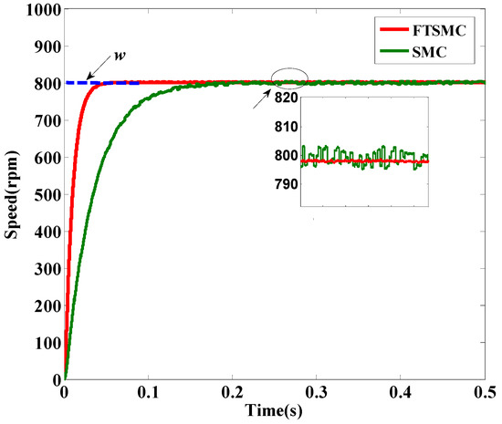
Figure 5.
Starting speed curves.
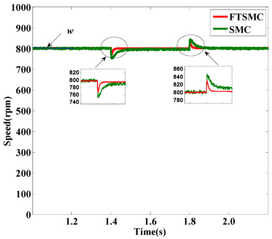
Figure 6.
Speed curves under loads.
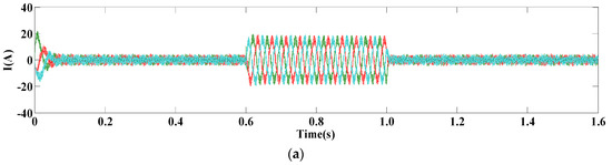
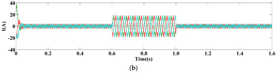
Figure 7.
Three-phase current curve of PMIWM. (a) FTSMC, (b) sliding mode control (SMC).
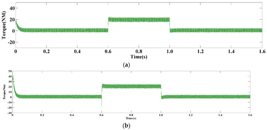
Figure 8.
Observation values of torque. (a) FTSMC, (b) SMC.
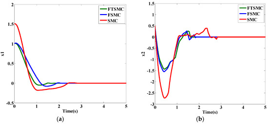
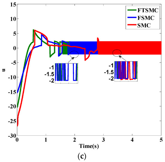
Figure 9.
Sliding mode parameters of PMIWM. (a) State errors x1, (b) state errors x2, (c) control input U.
As shown in Figure 5, the red curve presents the speed simulation based on FTSMC, and the green curve shows that based on SMC. It can be observed that the FTSMC strategy can respond more quickly, while the speed performance of the SMC strategy is poorer, consumes more time to reach the reference speed, and greatly fluctuates under state-steady performance. As shown in Figure 6, the comparison of the two curves shows the FTSMC strategy had better dynamic performance when receiving a load torque. It can be seen that the FTSMC strategy needed less time to regulate the system to a steady state. Also, the overshoot of the FTSMC strategy was smaller than that of the SMC strategy. Table 3 shows the comparison of the speed responses of the FTSMC and SMC strategies.
Table 3.
Comparison of the speed responses by the FTSMC and SMC strategies.
Figure 7a,b shows the three-phase current simulation response curve. It can be seen that the three-phase current response of the FTSMC strategy had smaller overshoot than that of the SMC strategy, so the FTSMC strategy was more stable.
Figure 8a,b shows the simulation curves of the two control strategies when the load torque increased from 1 N·m to 20 N·m at 0.6 s and decreased from 20 N·m to 1 N·m at 1.0 s. When the PMIWM started under a torque of 1 N·m, the FTSMC strategy had a smaller overshoot than the SMC strategy. When the speed reached a steady state, the FTSMC strategy had less fluctuation than the SMC strategy, but the adjustment time was longer.
Figure 9a–c shows the approaching simulation of state errors x1, x2 and control input U. It can be seen that the approaching time of x1, x2, and U were faster under the strategy of FTSMC than under that of SMC and FSMC and also that the fluctuation of U was smaller under the strategy of FTSMC. The approaching time of these three parameters and the fluctuation of U are shown in Table 4.
Table 4.
Comparison of the sliding parameters of the FTSMC and SMC strategies.
In order to verify the performance of the FTSMC strategy, relevant experiments were done based on a TMS320F28335 digital control board (made in Guangzhou, China). The experimental bench is shown in Figure 10 [33].
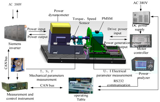
Figure 10.
Experimental bench of PWIWM.
The operating table, connected with the control instrument via a CAN bus and connected with a power analyzer via RS232, sent the instructions in the process of the experiment. A Siemens inverter (made in Beijing, China) was connected with the control instrument via CAN communication.
The first experiment indicated the dynamic performance of the FTSMC and SMC strategies, as shown in Figure 11. The second experiment indicated the currents id and iq of the FTSMC and SMC strategies, which are shown in Figure 12 and Figure 13, respectively.
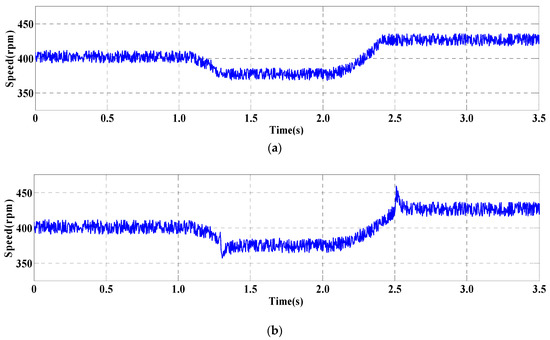
Figure 11.
Dynamic performance of PMIWM. (a) FTSMC, (b) SMC.
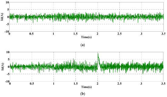
Figure 12.
Current id of PMIWM. (a) FTSMC, (b) SMC.
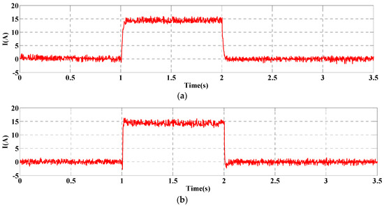
Figure 13.
Current iq of PMIWM. (a) FTSMC, (b) SMC.
Figure 11 shows the dynamic performance of the FTSMC and SMC strategies with changing speed commands, where the speed of PMIWM started at 500 r/min then reduced to 450 r/min at 1.0 s and increased to 550 r/min at 2.0 s. It can be seen that the dynamic performance of the FTSMC strategy had a shorter adjust time when receiving a changing speed command, and the overshoot of the FTSMC strategy was less than 15 r/min, while that of SMC strategy was more than 20 r/min. Furthermore, the chattering and ripple of the FTSMC strategy were reduced more effectively compared with those of the SMC, making the speed ripple of FTSMC about 50% of that under the SMC strategy.
As shown in Figure 12, the current id under the SMC strategy had bigger chattering than that of the FTSMC. It can be seen that the biggest fluctuation value was almost 10 A under the SMC strategy, while the current curve of id was ideal under the FTSMC strategy.
As shown in Figure 13, the current under the FTSMC strategy had a quicker response to the changing speed commands, which saved about 38% of the response time under the SMC strategy. Additionally, the overshoot of FTSMC strategy was about 23% of that under the SMC strategy, and the chattering of current under the FTSMC strategy was obviously reduced.
In summary, compared with the other strategy, the FTSMC strategy:
- had a better start response performance
- had a smaller overshot phenomenon
- had ideal steady-state performance
- when increasing and decreasing the load, saved about 68% of the adjust time which was needed in the SMC strategy.
- had ideal robust performance
- had a smaller chattering phenomenon because of the design of fuzzy rules.
5. Conclusions
In this paper, an FTSMC strategy with a load torque observer was investigated for the control of a PMIWM, and fuzzy rules were designed to reduce the chattering phenomenon. On the basis of theoretical analysis, simulation, and experimental results, the conclusions are as follows:
- by implementing the FTSMC approaching law, the main finding is that the proposed method can accelerate the approaching speed of the control system effectively, which can increase the start-up speed and response performance of PMIWMs;
- through torque disturbance observer, the PMIWM control can detect the torque load and compensate it in real time, which effectively decreases the control error and improves the control accuracy;
- the fuzzy controller proposed in this paper can reduce the chattering phenomenon significantly, which can improve the control stability and robust performance of the PMWIM.
All in all, the simulation and experiments results demonstrated that the proposed control strategy can not only increase the response speed and start-up speed of PMWIMs but also improve their dynamic performance and stable performance effectively.
The limitation of this study is that the fuzzy rules were designed by experience. Although these fuzzy rules can effectively alleviate the influence of the chattering phenomenon of the system, better fuzzy rules may exist to solve the problem of the chattering phenomenon and improve the control performance of the PMIWM.
Author Contributions
Conceptualization, H.H.; funding acquisition, Q.T.; methodology, M.P.; software, C.J.; writing—original draft preparation, H.H.; writing—review and editing, H.H.; project administration, Q.T. performed the experiments, J.X. All authors have read and agreed to the published version of the manuscript.
Funding
This research was funded by the National Key Research and Development Plan, grant number (2016YFC0802903) and the National Natural Science Foundation of China, grant Number (61671470).
Acknowledgments
The authors would like to thank the Army Engineering University of PLA for supporting the research equipment and the dissemination of this work. The authors would also like to thank the anonymous reviewers for providing useful suggestions and valuable comments that resulted in the improved quality of the paper.
Conflicts of Interest
The authors declare no conflict of interest.
References
- Martinez, C.M.; Hu, X.; Cao, D.; Wellers, M. Energy Management in Plug-in Hybrid Electric Vehicles: Recent Progress and a Connected Vehicles Perspective. IEEE Trans. Veh. Technol. 2017, 66, 4534–4549. [Google Scholar] [CrossRef]
- Hu, X.; Martinez, C.M.; Yang, Y. Charging, power management, and battery degradation mitigation in plug-in hybrid electric vehicles: A unified cost-optimal approach. Mech. Syst. Signal Process. 2017, 87, 4–16. [Google Scholar] [CrossRef]
- Jain, M.; Williamson, S.S. Suitability analysis of in-wheel motor direct drives for electric and hybrid electric vehicles. In Proceedings of the Electrical Power & Energy Conference, Halifax, NS, Canada, 25–27 August 2010. [Google Scholar]
- Shokri, M.; Kebriaei, H. Mean Field Optimal Energy Management of Plug-In Hybrid Electric Vehicles. IEEE Trans. Veh. Technol. 2018, 68, 113–120. [Google Scholar] [CrossRef]
- Donato, G.D.; Scelba, G.; Pulvirenti, M.; Scarcella, G.; Capponi, F.G. Low-Cost, High-Resolution, Fault-Robust Position and Speed Estimation for PMSM Drives Operating in Safety-Critical Systems. IEEE Trans. Power Electron. 2018, 34, 550–564. [Google Scholar] [CrossRef]
- Zhou, Y.; Chen, G. Predictive DTC Strategy with Fault-Tolerant Function for Six-Phase and Three-Phase PMSM Series-Connected Drive System. IEEE Trans. Ind. Electron. 2018, 65, 9101–9112. [Google Scholar] [CrossRef]
- Yong, L.; Li, B.; Xing, X.; Sun, X. A Nonlinear Decoupling Control Approach Using RBFNNI-Based Robust Pole Placement for a Permanent Magnet In-Wheel Motor. IEEE Access 2017, 6, 1844–1854. [Google Scholar]
- Zhou, K.; Sun, Y.C.; Wang, X.D.; Yan, D. Active disturbance rejection control of PMSM speed control system. Electr. Mach. Control 2018, 22, 57–63. [Google Scholar]
- Qin, Y.; He, C.; Shao, X.; Du, H.; Xiang, C.; Dong, M. Vibration mitigation for in-wheel switched reluctance motor driven electric vehicle with dynamic vibration absorbing structures. J. Sound Vib. 2018, 419, 249–267. [Google Scholar] [CrossRef]
- Ouhab, M.; Khatir, Z.; Ibrahim, A.; Ousten, J.; Mitova, R.; Wang, M. New Analytical Model for Real-Time Junction Temperature Estimation of Multi-Chip Power Module Used in a Motor Drive. IEEE Trans. Power Electron. 2018, 33, 5292–5301. [Google Scholar] [CrossRef]
- Li, X.; Sun, Y.; Shen, T. Vibration stability analysis of dual motor harmonic synchronous excitation nonlinear vibration conveyer. Trans. Can. Soc. Mech. Eng. 2018, 42, 419–426. [Google Scholar] [CrossRef]
- Xu, G.; Liu, G.; Shan, J.; Chen, Q. Analysis of a Hybrid Rotor Permanent Magnet Motor Based on Equivalent Magnetic Network. IEEE Trans. Magn. 2018, 54, 8202109. [Google Scholar] [CrossRef]
- Lei, Y.; Ke, W.; Lu, Z.; Ge, Q.; Li, Z.; Li, Y. An Improved Torque and Current Pulsation Suppression Method for Railway Traction Drives Under Fluctuating DC-link Voltage. IEEE Trans. Power Electron. 2017, 33, 8565–8577. [Google Scholar] [CrossRef]
- Yan, R.; Li, B.; Fu, Z. Sensorless control of PMSMs based on parameter-optimized MRAS speed observer. In Proceedings of the IEEE International Conference on Automation & Logistics, Qingdao, China, 1–3 September 2008. [Google Scholar]
- Calligaro, S.; Petrella, R. Accuracy and robustness improvement in sensorless PMSM drives at low-speed by direct-axis current injection. In Proceedings of the IEEE International Conference on Sensorless Control for Electrical Drives, Munich, Germany, 17–19 October 2013. [Google Scholar]
- Jeon, H.; Lee, J.; Han, S.; Kim, J.H.; Hyeon, C.J.; Kim, H.M.; Kang, H.; Ko, T.K.; Yoon, Y.S. PID control of an Electromagnet-based Rotary HTS Flux Pump for maintaining constant field in HTS Synchronous Motors. IEEE Trans. Appl. Supercond. 2018, 28, 5207605. [Google Scholar] [CrossRef]
- Jung, J.W.; Leu, V.Q.; Do, T.D.; Kim, E.; Choi, H.H. Adaptive PID Speed Control Design for Permanent Magnet Synchronous Motor Drives. IEEE Trans. Power Electron. 2014, 30, 900–908. [Google Scholar] [CrossRef]
- Cai, B.; Zhao, Y.; Liu, H.; Xie, M. A Data-Driven Fault Diagnosis Methodology in Three-Phase Inverters for PMSM Drive Systems. IEEE Trans. Power Electron. 2017, 32, 5590–5600. [Google Scholar] [CrossRef]
- Dinardo, L.; Brown, V.; Perez, E.; Bunin, N.; Sullivan, K.E. A single-center study of hematopoietic stem cell transplantation for primary immune deficiencies (PIDD). Pediatr. Transplant. 2012, 16, 63–72. [Google Scholar] [CrossRef]
- Zheng, W.; Wang, X.; Cao, J.; Cheng, M.; Hu, Y. Direct Torque Control of T-NPC Inverters Fed Double-Stator-Winding PMSM Drives With SVM. IEEE Trans. Power Electron. 2018, 33, 1541–1553. [Google Scholar]
- Lin, S.; Zhang, W. An adaptive sliding-mode observer with a tangent function-based PLL structure for position sensorless PMSM drives. Int. J. Electr. Power Energy Syst. 2017, 88, 63–74. [Google Scholar] [CrossRef]
- Qi, Y.; Bostanci, E.; Gurusamy, V.; Akin, B. A Comprehensive Analysis of Short Circuit Current Behavior in PMSM Inter Turn Short Circuit Faults. IEEE Trans. Power Electron. 2018, 33, 10784–10793. [Google Scholar] [CrossRef]
- Aljehaimi, A.M.; Pillay, P. Novel Flux Linkage Estimation Algorithm for a Variable Flux PMSM. IEEE Trans. Ind. Appl. 2018, 54, 2319–2335. [Google Scholar] [CrossRef]
- Liu, B.; Badcock, R.; Hang, S.; Fang, J. A Superconducting Induction Motor with a High Temperature Superconducting Armature: Electromagnetic Theory, Design and Analysis. Energies 2018, 11, 792. [Google Scholar] [CrossRef]
- Malvezzi, F.; Coelho TA, H. Error analysis for an active geometry control suspension system. J. Braz. Soc. Mech. Sci. Eng. 2018, 40, 558. [Google Scholar] [CrossRef]
- Schoonhoven, G.; Uddin, M.N. Harmonic Injection-Based Adaptive Control of IPMSM Motor Drive for Reduced Motor Current THD. IEEE Trans. Ind. Appl. 2017, 53, 483–491. [Google Scholar] [CrossRef]
- Jon, U.; Kim, J.; Lee, H. DC Motor Current Control Algorithm Using Proportional-Integral LQT with Disturbance Observer. Int. J. Automot. Technol. 2018, 19, 959–967. [Google Scholar] [CrossRef]
- Wu, Z.; Du, C. The Parameter Identification of PMSM Based on Improved Cuckoo Algorithm. Neural Process. Lett. 2019, 50, 2701–2715. [Google Scholar] [CrossRef]
- Dursun, M.; Boz, A.F.; Kale, M.; Karabacak, M. Sensorless control application of PMSM with a novel adaptation mechanism. Neural Comput. Appl. 2018, 29, 87–103. [Google Scholar] [CrossRef]
- Lukichev, D.V.; Demidova, G.L. Speed control in PMSM drive with non-stiff load and unknown parameters using PI- and fuzzy adaptive PID controllers. In Proceedings of the International Conference on Industrial Engineering, Rome, Italy, 3–5 January 2017. [Google Scholar]
- Chaoui, H.; Khayamy, M.; Aljarboua, A.A. Adaptive Interval Type-2 Fuzzy Logic Control for PMSM Drives with a Modified Reference Frame. IEEE Trans. Ind. Electron. 2017, 64, 3786–3797. [Google Scholar] [CrossRef]
- Saihi, L.; Bouhenna, A.; Chenafa, M.; Mansouri, A. A robust sensorless SMC of PMSM based on sliding mode observer and extended Kalman filter. In Proceedings of the International Conference on Electrical Engineering, Boumerdes, Algeria, 13–15 December 2015. [Google Scholar]
- Huang, H.; Bhuiyan, A.M.Z.; Tu, Q.; Jiang, C.; Xue, J.; Ming, P.; Li, P. Fuzzy sliding mode control of servo control system based on variable speeding approach rate. Soft Comput. 2019, 23, 13477. [Google Scholar] [CrossRef]
- Zhu, J.G.; Lei, G.; Guo, Y.G.; Wang, T.S.; Ma, B. A robust design optimization method for manufacturing SMC-PMSMs and drive systems of six sigma quality. In Proceedings of the 2017 7th International Conference on Power Electronics Systems and Applications—Smart Mobility, Power Transfer & Security (PESA), Hong Kong, China, 12–14 December 2018. [Google Scholar]
- Liu, Z.; Wei, H.; Liu, K.; Zhong, Q.-C. Global Identification of Electrical and Mechanical Parameters in PMSM Drive based on Dynamic Self-Learning PSO. IEEE Trans. Power Electron. 2018, 33, 10858–10871. [Google Scholar] [CrossRef]
- Zhou, Z.; Zhang, B.; Mao, D. Robust Sliding Mode Control of PMSM Based on a Rapid Nonlinear Tracking Differentiator and Disturbance Observer. Sensors 2018, 18, 1031. [Google Scholar] [CrossRef]
- Hu, S.; Liang, Z.; Zhang, W.; He, X. Research on the Integration of Hybrid Energy Storage System and Dual Three-Phase PMSM Drive in EV. IEEE Trans. Ind. Electron. 2017, 65, 6602–6611. [Google Scholar] [CrossRef]
- Jiang, Y.; Wei, X.; Mu, C.; Liu, Y. Improved Deadbeat Predictive Current Control Combined Sliding Mode Strategy for PMSM Drive System. IEEE Trans. Veh. Technol. 2017, 67, 251–263. [Google Scholar] [CrossRef]
- Mendoza-Mondragón, F.; Hernández-Guzmán, V.M.; Rodríguez-Reséndiz, J. Robust Speed Control of Permanent Magnet Synchronous Motors Using Two-Degrees-of-Freedom Control. IEEE Trans. Ind. Electron. 2018, 65, 6099–6108. [Google Scholar] [CrossRef]
- Yan, J.; Wang, H.; Huang, S.; Lan, Y. Load Disturbance Observer-Based Complementary Sliding Mode Control for PMSM of the Mine Traction Electric Locomotive. Int. J. Fuzzy Syst. 2019, 21, 1051–1058. [Google Scholar] [CrossRef]
- Hao, Y.; Xu, Y.; Cai, F.; Zhang, H.; Zhao, W.; Gerada, C. PWM-VSI Fault Diagnosis for PMSM Drive Based on Fuzzy Logic Approach. IEEE Trans. Power Electron. 2018, 34, 759–768. [Google Scholar]
- Choi, G.; Jahns, T.M. Analysis and Design Recommendations to Mitigate Demagnetization Vulnerability in Surface PM Synchronous Machines. IEEE Trans. Ind. Appl. 2018, 99, 1. [Google Scholar] [CrossRef]
- Guzinski, J.; Abu-Rub, H.; Diguet, M.; Krzeminski, Z.; Lewicki, A. Speed and Load Torque Observer Application in High-Speed Train Electric Drive. IEEE Trans. Ind. Electron. 2010, 57, 565–574. [Google Scholar] [CrossRef]


© 2020 by the authors. Licensee MDPI, Basel, Switzerland. This article is an open access article distributed under the terms and conditions of the Creative Commons Attribution (CC BY) license (http://creativecommons.org/licenses/by/4.0/).