1. Introduction
The smart grid is regarded to be the next generation of traditional power system that relies on two-way power flow as well as information exchange competencies [
1]. Conventional grid includes power generation, transmission, distribution, control centers, and end users [
2]. Key benefits pertaining to smart grid include two-way communication services as well as its ability to further use the renewable energy resources [
3]. Smart microgrids, as part of the bigger power system, could provide electricity to smaller areas operating in island or grid-connected mode. Smart microgrid also offer consumers with enhanced control, monitoring, and new service technologies [
4]. With regards to grid connection mode, a common connection point (PCC) connects the microgrid to the utility network. In islanded mode, microgrid functions separately and meets the control objectives autonomously [
5]. It is difficult to control microgrid in islanded mode as multilevel control techniques are needed to ensure that voltage and frequency security constraints as well as other system’s technical constraints are efficiently met.
A stable and appropriate power management strategy is needed to operate hybrid microgrid networks in order to control load sharing amongst DC and AC power sources. Controlling power-sharing in DC and AC microgrids has been a focus for various studies. However, until now, there have been less efforts in power management amongst AC and DC power sources concerning hybrid systems. The reliable power-sharing method, which has been motivated by droop control pertaining to conventional synchronous alternator governor systems, has been used for power-sharing control in microgrids [
6]. The frequency droop features involve working of different converters together for determining the corresponding reference power. With regards to the drooping control theory, load balancing includes all drooping control converters based on drooping slope [
7].
Few researchers have studied the power-sharing pertaining to hybrid microgrid independent mode [
8,
9,
10]. For sharing realization pertaining to AC microgrid, commonly employed parameters are active power and frequency (P–F), reactive power and voltage (Q–V) features [
11]. With regards to DC microgrid, it is recommended to employ both current and voltage (I–V), active power and voltage (P–V) droop features [
12]. However, coordination between two microgrids, i.e., hybrid microgrid and power-voltage (P–V) droop features, is usually employed when it comes to DC microgrids being part of hybrid microgrid [
13]. In order to extend active power sharing pertaining to sources of both microgrids, also referred as proportional active power sharing, proper amount of active power between two microgrids needs to be exchanged by interlinking converter. With regards to this, determination of reference active power pertaining to interlinking converter is done by considering AC microgrid frequency as well as DC microgrid voltage for ensuring proper exchange of active power and achieving proportional power-sharing [
14,
15].
However, there are some limitations pertaining to the droop-based sharing strategy, which are also referred as primary control in hierarchical control structures. For instance, there could be inaccurate sharing due to variation in voltage magnitude for microgrid bus as a result of line impedances when voltage forms a part of realization pertaining to droop features [
16]. Various efforts have been put for eliminating or mitigating this error [
17,
18]. In [
19,
20], various corrective actions have been applied by injection of further harmonic signals into the line. However, such invasive methods include the drawback of line current distortion. In [
21], enabling signals are activated at specified intervals in order to achieve reactive power-sharing. Nevertheless, during this time interval, load fluctuations could result in stability problems as well as reactive power sharing errors. Authors in [
22] have given more accurate sharing by making use of low bandwidth communication links. However, implementation of such methods is key to secondary control. In [
23], obtaining of precise reactive power-sharing is done amongst AC sources pertaining to microgrid, in which radial connection of sources to common bus has been established. In the same study, regulation of output impedance pertaining to source has been done in a manner that total source impedance and source capacity are inversely proportional. However, this control structure could also result in low voltage quality due to output impedance voltage droop. In [
24], adjustment is done to the reactive power-voltage slope pertaining to AC featured of AC source in order to compensate voltage drop that is associated with source’s output impedance. In this work, it has been regarded that across the source output impedance, voltage droop is autonomous with regards to source voltage differences, which could result in errors pertaining to reactive power sharing. In [
25], similar study has been proposed by employing current-voltage droop concept in order to offer accurate current sharing amongst DC sources, which is not a common thing for hybrid microgrid applications. In [
26], authors have put forward power derivative integral terms pertaining to conventional droop controllers in order to enhance dynamic response as well as decrease circulation current amongst parallel inverters. In [
27], addition of an adaptive derivative term is done for droop control that also allows minimizing overshoot with regards to the current as well as enhance stability. In [
28], in order to accurately adjust drooping parameters when faced with various load conditions, central controller with low bandwidth communication has been employed.
The well-established droop control and virtual synchronous generator control schemes in the literature are proposed in [
29] to allow power sharing through voltage source inverters. This means that the voltage source inverter and the voltage magnitudes can be associated with both actual and reactive output power through decentralized power sharing. In spite of its precise actual power sharing, it is noticed that due to the mismatched impedances of the grid, the reactive, unbalanced, and harmonic power share precision cannot be assured [
30].
The voltage drop over distribution feeders has been calculated in [
31] for the purpose of balancing load voltage and it is added to the voltage reference provided by the Q–V droop control method which leads to a balanced load voltage. An improved droop control strategy is proposed in [
32] based on self-tuning droop curves to adjust each phase droop curve with the load variance in real time and to mitigate the voltage unbalance of PCC.
In its entirety, the following drawbacks were associated in the reviewed literature:
The degree of issue mainly relies on the size of DC-link capacitance, which is chosen traditionally in order to deal with certain filter requirements like to decrease voltage fluctuation cause by switching current.
Even though the above-mentioned studies stressed on enhancing transient dynamics pertaining to the average power control, not a single study was able to address the instantaneous transient power impact on parallel inverters’ stability. Moreover, not a single study regarded the impact cast by mismatched line impedances on the damping and circulated power of the microgrid system.
To deal with the aforementioned problems, this study puts forward a new robust control strategy pertaining to green energy application’s parallel operated inverters when faced with variable load as well as generation conditions. The key contributions of this work can be summarized as:
Hierarchical control structure has been recommended for both frequency and voltage restoration pertaining to grid-connected microgrid as well as islanded microgrid by accounting for the complete nonlinear system model, regardless of the parametric disturbances as well as uncertainties.
The impact pertaining to mismatched line impedances has been evaluated based on the performance of parallel inverters that were supplied by various energy sources, and it also investigates the instantaneous circulating power responses against microgrid’s stability. In addition, the system has been analyzed by employing microgrid’s small signal state space model that includes three inverters. In order to uphold microgrid’s stability, we recommend employing two controller schemes that account for supplementary phase as well as frequency loops. The most effective controller scheme possessing the least action linked with DC- link voltage have been employed for participation factor assessment. Simulation was applied to validate the proposed controller.
Distributed consensus-based control scheme has been suggested to precisely carry out power sharing when there is frequency restoration. The proposed strategy can be regarded as fully distributed method that allows distributing communication and computational tasks amongst local controllers by working in parallel, which is also more scalable, flexible and insusceptible to single point failure.
Hybrid microgrid has been studied by accounting for typical energy storage systems, unbalanced and balanced load switch and nonlinear and linear loads offered via description of model containing all necessary data to deal with the aforementioned studies.
The remainder of this paper is structured as follows.
Section 2 presents the description of the proposed system.
Section 3 describes the microgrid control methods.
Section 4 presents the mathematical model of the distributed hybrid generation system, while
Section 5 elaborates on the dynamic analysis of system.
Section 6 presents the proposed control strategy for PV/wind/storage energy system.
Section 7 presents the proposed controller to limit voltage of DC link.
Section 8 presents the analysis of the participation factor, followed by the controller design procedure outlined in
Section 9.
Section 10 presents results of the proposed system and
Section 11, concludes the paper.
7. Proposed Controller to Limit DC-Link Voltage
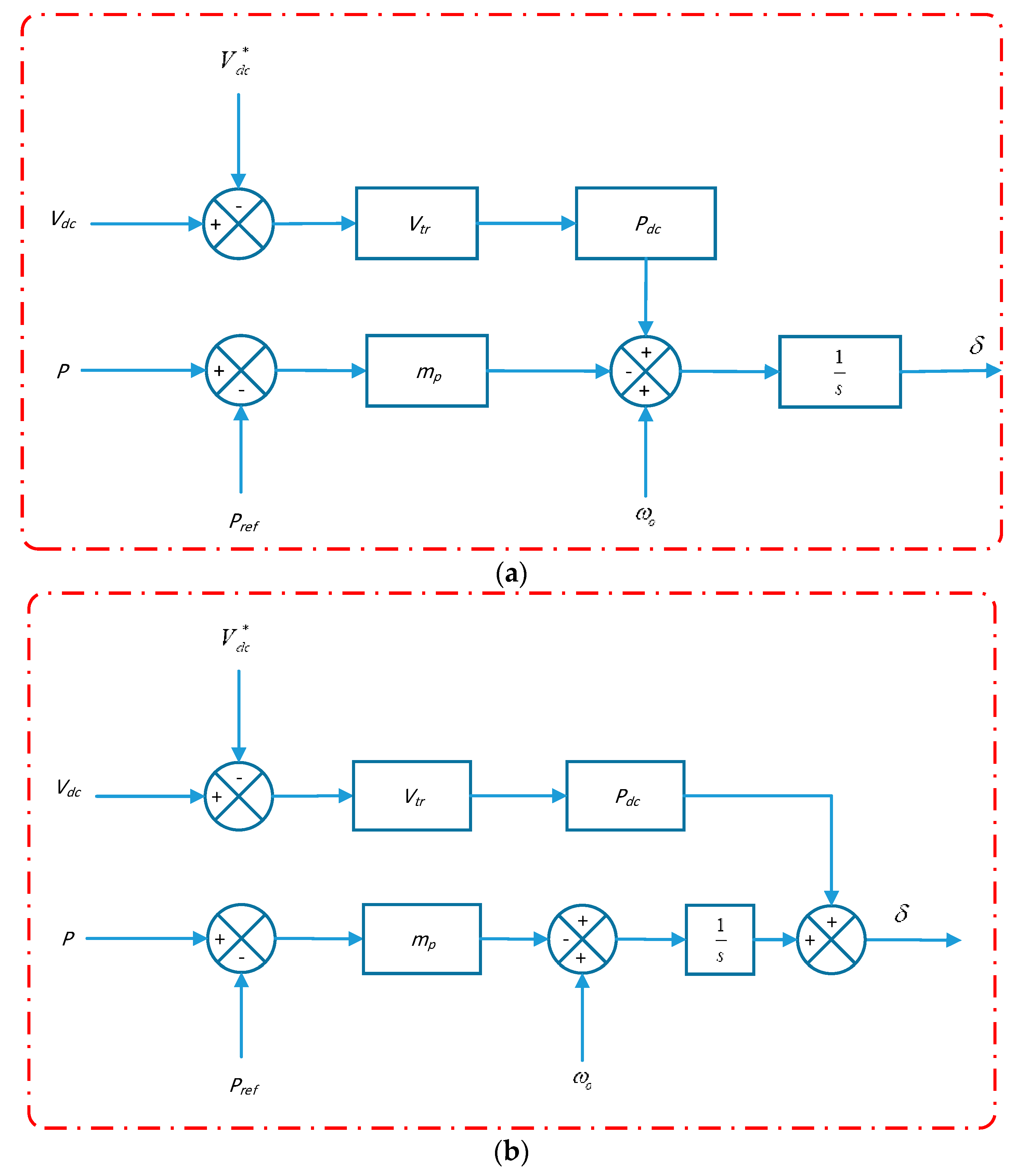
To limit voltage of DC link during the normal operation of a microgrid, the DC-link voltage after exceeding a triggering value () will affect the frequency state which influences the active power.
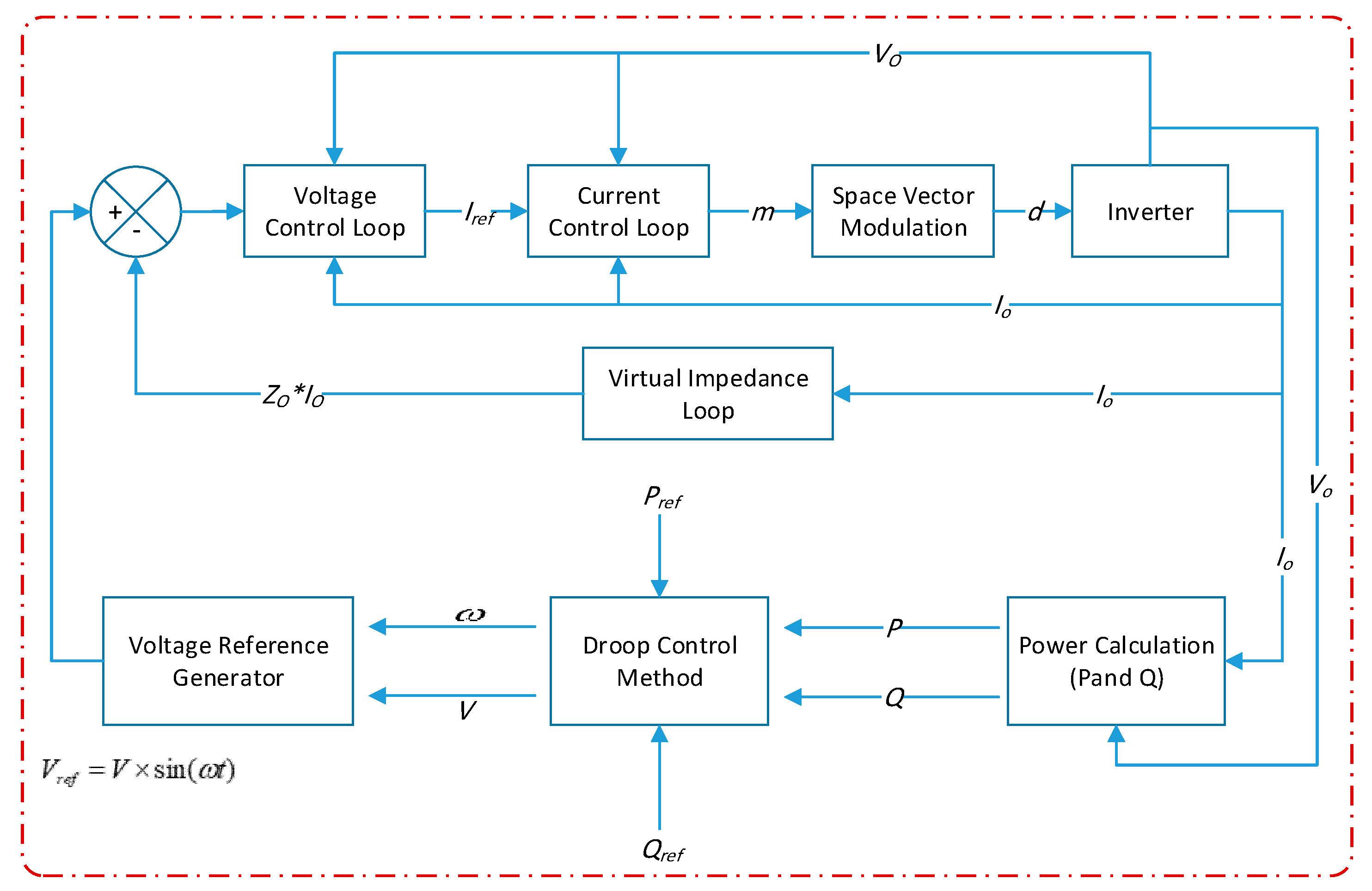
To assure stable responses among hybrid microgrid networks in normal operations,
Figure 17 describes two new control method proposals. When the voltage of DC-link surpasses a triggering value, the
, a loop is started. This supplementary loop influences either the (a) phase state or (b) the frequency. In this research, an investigation is conducted to determine the state that has key effect on DC-link voltages. In this way, the controller effort needed to control the DC link voltage and use smaller control gains, which in turn preserves stability.
Through analysis of the first control track, as shown in
Figure 17a, wherein controller output signaling is used to manipulate frequency state, the small-signal output frequency described in Equation (1) is thereby derived:
where in
represents the smaller signal state of voltage DC-link, which is derived as:
where
is the linearizing factor of the DC voltage and the negative sign indicates the negative flow of power. In the assumption that instantaneous and average powers are equal and through substitution of Equation (45) for Equation (44), we derive Equation (46):
Therefore, the phase state is obtained as Equation (47):
For the control system shown in
Figure 17b, the frequency and phase-states are as follows:
An evaluation of Equation (46) with Equation (48) shows that the technique demonstrated in
Figure 17a operates as the Proportional Integral (
) controller of the output power. However, this approach may not offer faster action against introduced power. Conversely, the technique demonstrated in
Figure 17b operates as the proportional derivative (
) controller. In this approach, the power derivative is not applied directly, although the action is realized in the proposed loop. The derivative term is well-known for providing the fastest response needed for limiting any introduced DC-link voltage and power rises. Additionally, when compared to Equation (49), an added pole is obtained at origin in Equation (47), thereby introducing a
phase lag that results in lower stability margins. In accord with the above discussions, the technique demonstrated in
Figure 17b is shown to perform better overall.
8. Analysis of the Participation Factor
Participation analysis was performed to attain further insight into the excellence of the technique, as indicated in
Figure 17b, over that demonstrated in
Figure 17a. The participation factor
in Equation (50) of eigenvalues on a state represents a measure of the influence of the state regarding the eigenvalue. Conversely, the participation factor
in Equation (51) of eigenvalues on a state represents a measure of whichever mode forms the majority of the response.
where
denotes the
state,
denotes the
mode. The eigenvalues for the system are calculated from Equation (43) as in
Table 4.
As the aim is to control the DC voltage state variable, we are looking for modes with key effects on the active power
P state variable, given the direct relationship of
with DC-link voltage.
Table 5 describes participation factors for eigenvalues on the system states. Eigen values
retain dominant influence on power responses. Operation of these modes can rework the active power response through transients, and thus, DC connection voltages can be reduced. Further analysis of the factor of participation is carried out to determine which states have key effects on these modes. Although the frequency is not a direct state, it includes a power output via a scalar function in relation to the power state as stated in Equation (11). Thus,
Table 6 describes the phase and participation of the power state in the modes investigated, as was established early on. The results indicate that phase state has greater effect than power state on mode, which works to shape output power and consequently DC-link voltage. This validates similar conclusions made in the last section, in that the method displayed in
Figure 17b performs better than that displayed in
Figure 17a, for it results in smaller controller gains required to effect similar actions.
10. Simulation Results
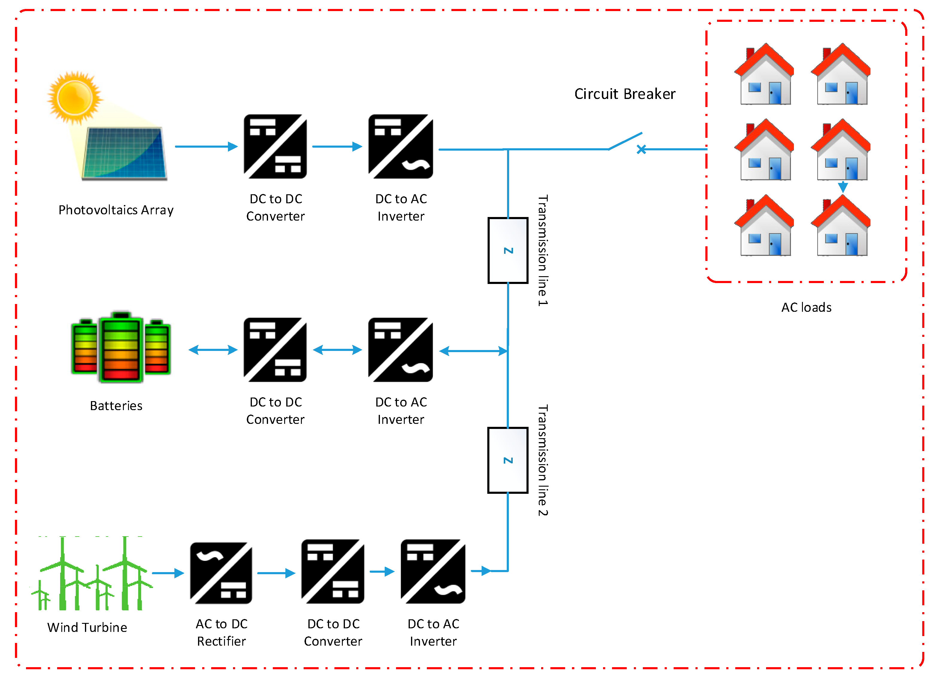
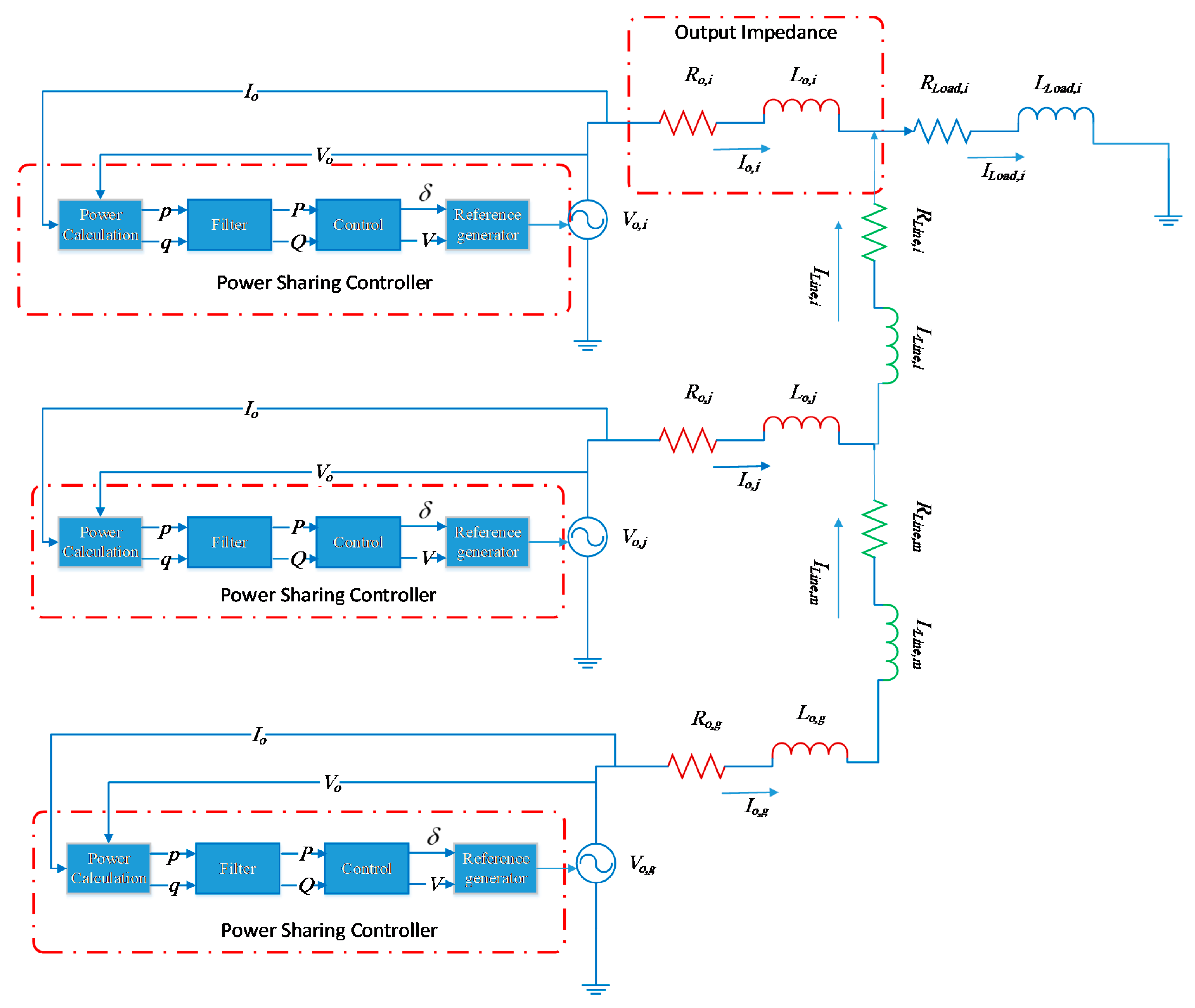
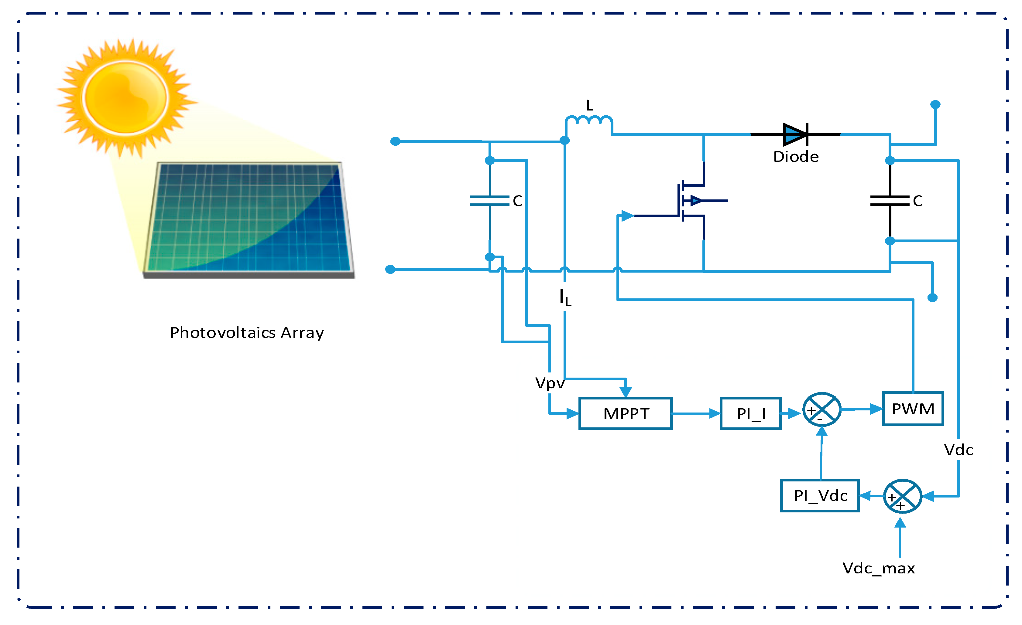
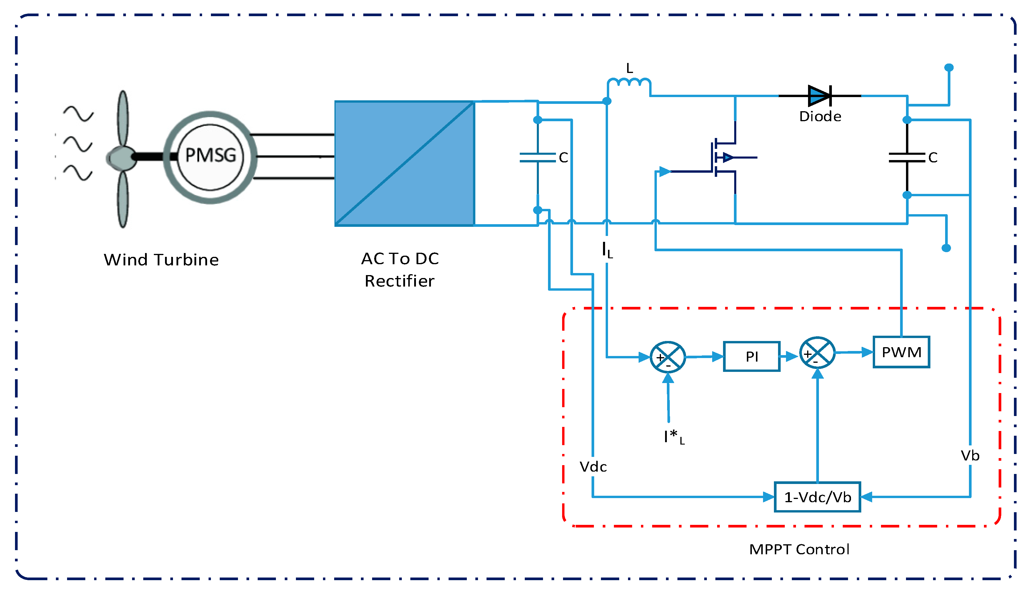
The suggested hybrid microgrid network comprising three inverters, as displayed in
Figure 1 in SimPowerSystem, is simulated in order to confirm the performance of the suggested control strategy. Inverters and converters are characterized in models of renewable energy source, as photovoltaics, wind turbines, and batteries. The parameters of the simulation are given in
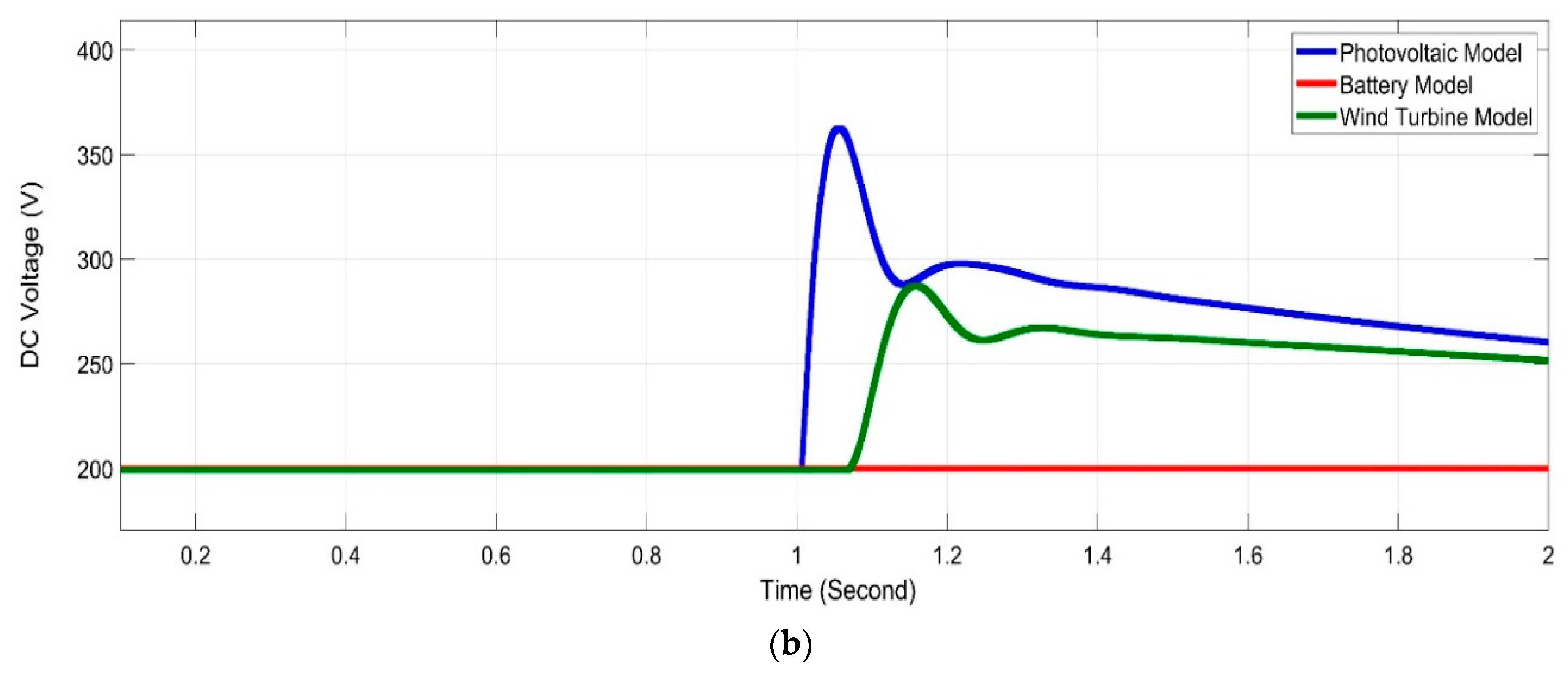
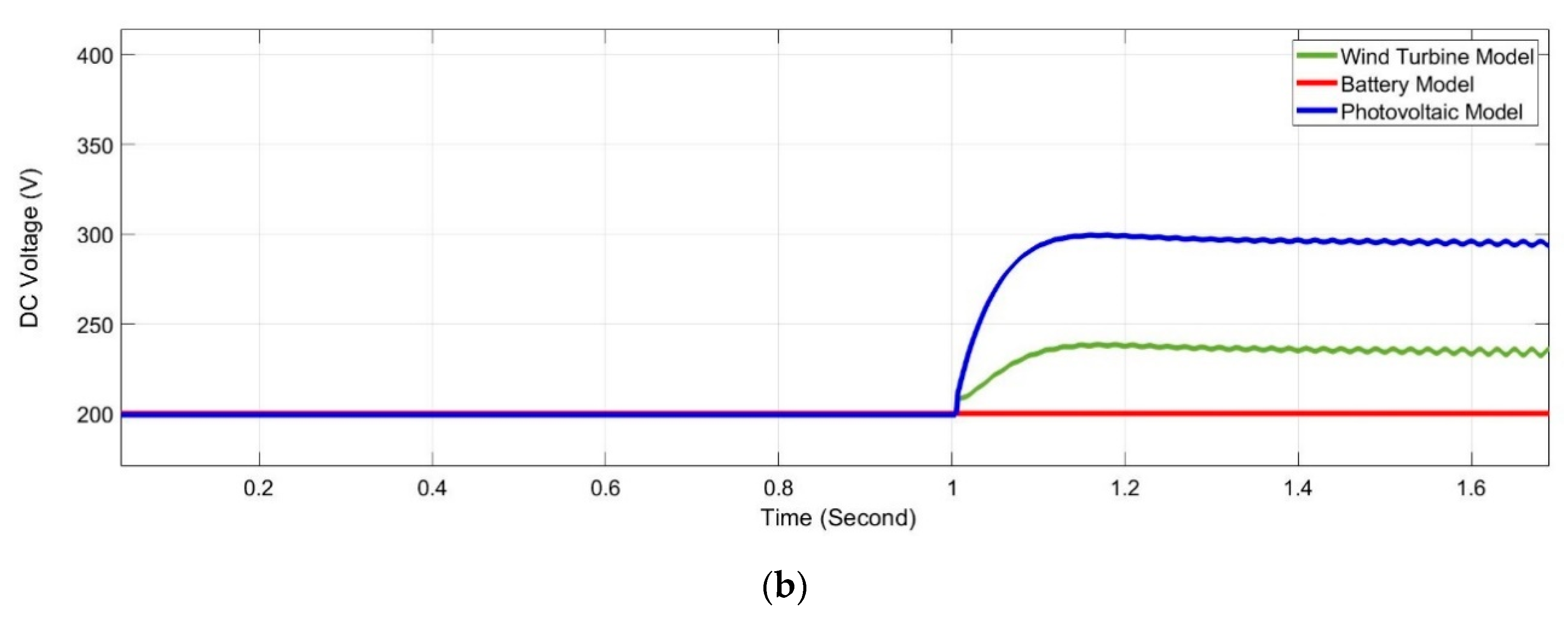
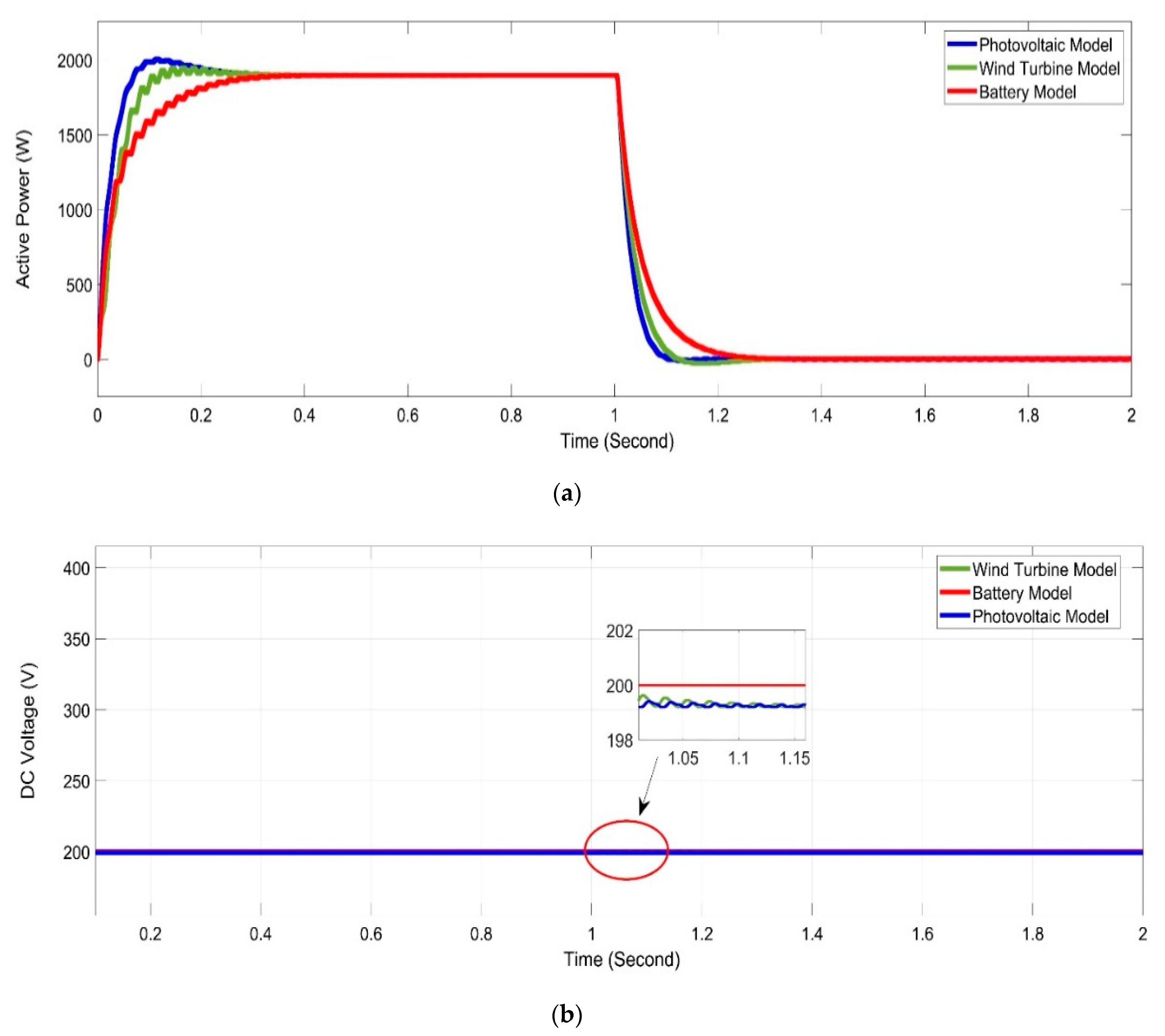
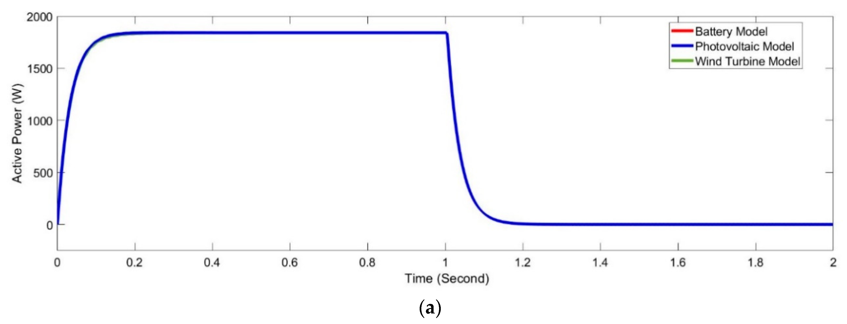
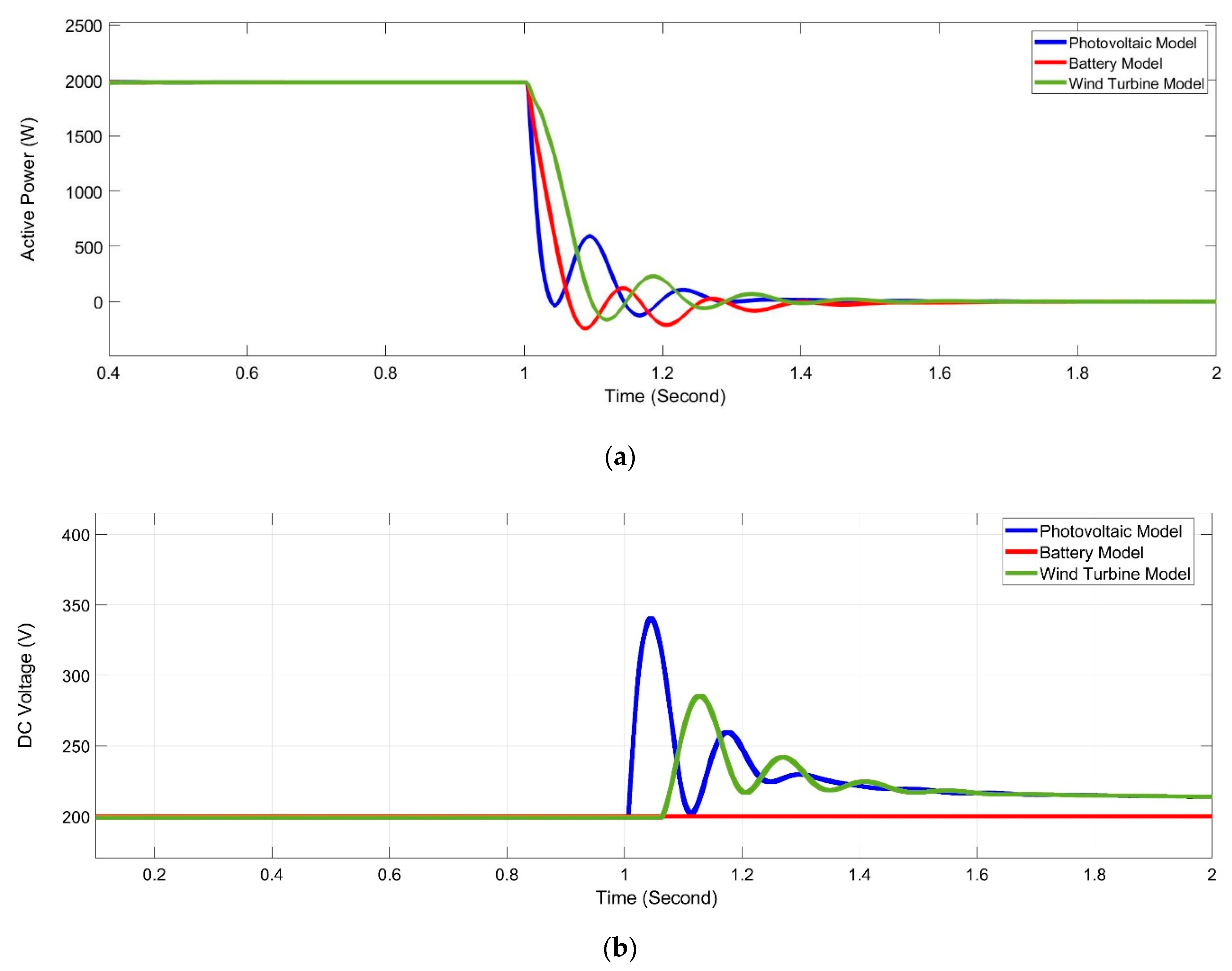
Table 7. DC-link voltage is acquired whenever loads instantaneously change from 100% of 6 kW down to 0%, with the resulting power response displayed in
Figure 19a. Clearly, the response remains well-damped due to the performance of the proposed controller that activates automatically whenever DC voltage rises above
. This result is worthy of comparison as shown in
Figure 13, which represents the same system except that the controller is not activated. Furthermore, DC-link voltage in
Figure 19b is constrained and remains below trip levels, which validates the efficiency of the suggested approach.
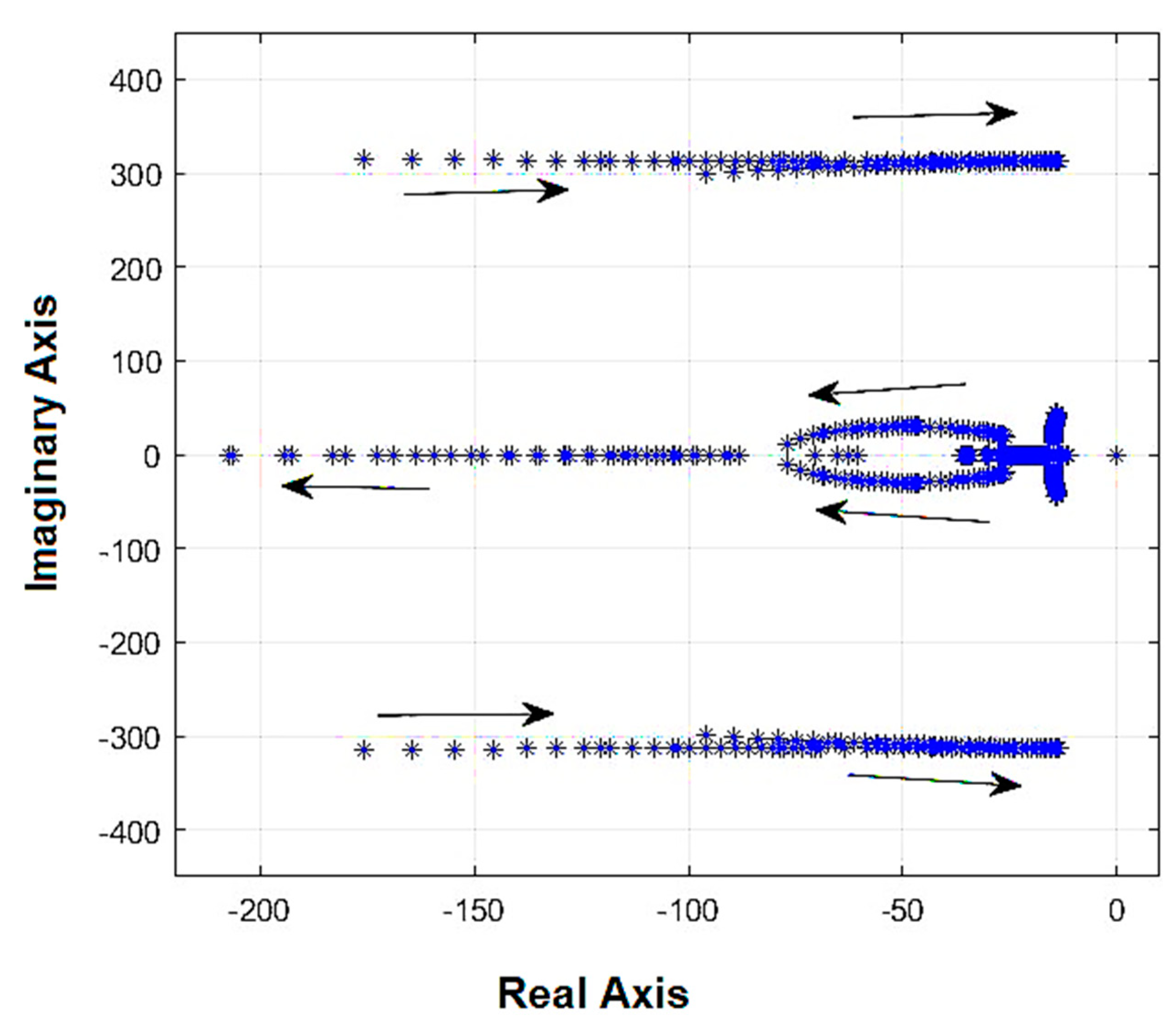
Figure 20 illustrates average active energy and response of DC voltage when proposed controller’s gain is
Pdc = 0.001. The system is unstable and oscillation frequency is 314 rad/second, this is consistent with the prediction in
Figure 18 as the system becomes unstable and oscillation frequency is 312 rad/second.
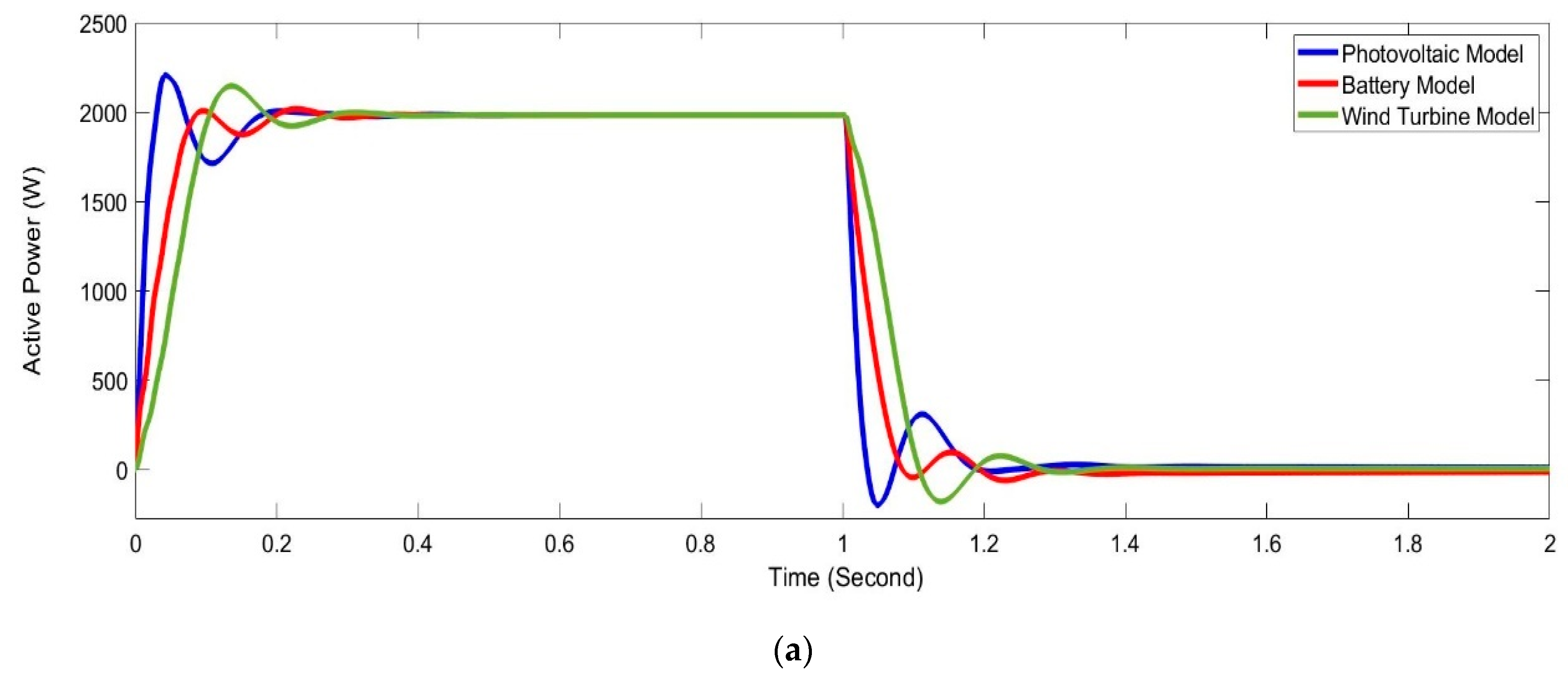
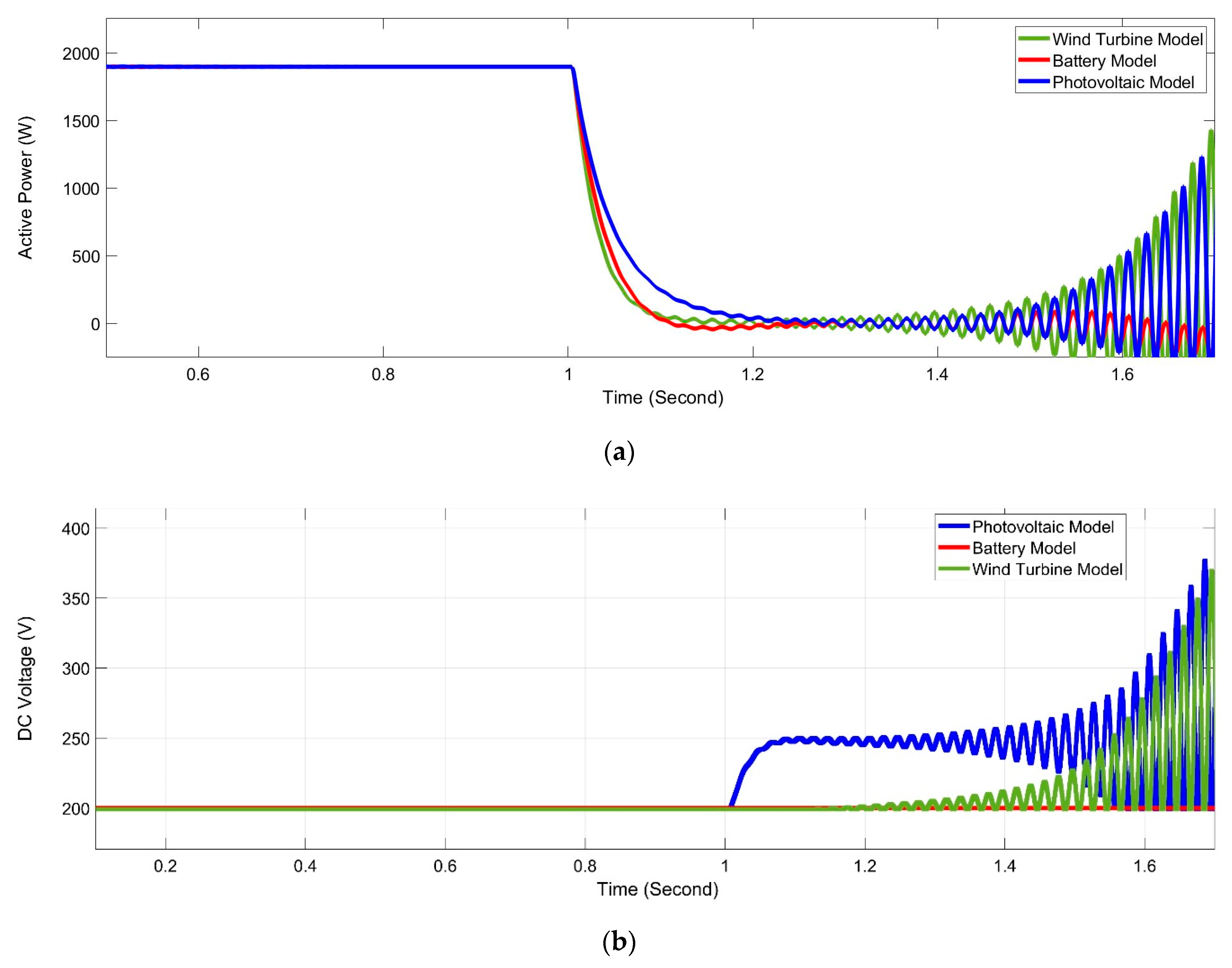
To validate the recommended approach in view of the excellence of technique indicated in
Figure 17b over that demonstrated in
Figure 17a,
Figure 21 describes response when control method, as displayed in
Figure 17a, is implemented with
. The gain was selected for its similar capacity to tuning DC-link voltage, as illustrate in
Figure 19b. Clearly, the gain exceeds that used in the suggested method, as shown in
Figure 17b, which therefore confirms that the suggested method requires less effort in regulating DC voltage. Furthermore, DC-link and power voltage responses can be highly oscillatory in comparison to that described in
Figure 19.
11. Conclusions
This research investigated the effect of mismatched line impedances on the stability of DC-link voltages under sudden load changes, as well as the performance of parallel inverters operating in hybrid microgrids. Studies showed that comparable droop gains do not assure similar power responses during transients in every case. If an appreciable line impedance mismatch exists, circulating power transients may degrade stability. The suggested technique was found to perform more efficiently than the frequency loop approach in stabilizing DC-link voltage states in microgrids. Any stable-state errors appeared solely during instances of zero-load transition. Nevertheless, this does not present a major issue when the load reconnects, as the level is sufficient to discharge the excess energy and thereby maintains zero error. The results of the simulation demonstrated also the improved performance and effectiveness of the suggested control approach. Additionally, the suggested control strategy exhibited much robustness against larger load variations. Furthermore, in an effort to avert the drawbacks of standard droop control, an enhanced droop control strategy derived from integrator current-sharing was developed. The MPPT method was used in both wind turbine and photovoltaic stations towards extracting maximum amounts of power from such hybrid power systems.
The new strategy aimed to unify the control loops for all inverters in each mode of operation and for different energy sources to be DC-voltage regulators. This structure immunized the stability of the DC-link voltage states and the overall reliability of the microgrid against sudden unplanned islanding. The control scheme was analyzed and tested by simulation. As future works, the following points are suggested: (I) implementing the presented strategy on a real network and comparing the results (II) the proposed control scheme can be extended to address the network-related issues, such as data loss, packet jamming, link failure, cyber-attack, etc., using a cyber-physical systems framework.

 ,
, 


