Abstract
Aiming at the application of a reversible three-phase pulse width modulation (PWM) converter with a wide range of AC side voltage and DC side voltage, a double fuzzy proportional integral (PI) controller for voltage outer loop was proposed. The structures of the proposed controller were motivated by the problems that either the traditional PI controller or single fuzzy PI controller cannot achieve high performance in a wide range of AC and DC voltage conditions. The presented double fuzzy controller studied in this paper is a sub fuzzy controller in addition to the traditional fuzzy PI controller; in particular, the sub fuzzy controller can get the auxiliary correction of PI control parameters according to the AC side voltage and the DC side given voltage variation of PWM converter after the reasoning of the sub fuzzy controller, while the traditional fuzzy PI controller outputs the correction of PI control parameters according to the DC voltage error and its error change rate. In this paper, the traditional fuzzy PI controller can be called the main fuzzy controller, and the adaptive adjustment of PI control parameters of the voltage outer loop is the sum of the PI parameter correction output by the main fuzzy controller and the auxiliary PI parameter correction output by the sub fuzzy controller. Finally, the experimental results show that the reversible three-phase PWM converter can achieve excellent dynamic and static performance in a wide range of AC voltage and DC voltage applications by using the proposed double fuzzy PI controller.
1. Introduction
With the rapid development of power electronic technology in recent years, the reversible three-phase PWM converter circuit has gradually replaced the traditional uncontrolled rectifier circuit such as a diode or thyristor because of its advantages of high power factor, low harmonic content, and energy bidirectional flow [1,2,3]. Therefore, the three-phase PWM converter has been widely used in a switching mode power supply and especially electric drive fields [4,5,6].
At present, the traditional double closed-loop PI controller is usually used for a three-phase PWM converter, and the PI parameters are usually obtained for a specific operating condition [7,8]. Considering that one operating condition corresponds to a model, the PI control parameters deduced by the mathematical model are usually the optimal parameters under the corresponding operating condition [9,10,11]. However, the traditional PI controller cannot adaptively change the control parameters to adapt to the changing operating conditions; therefore, in view of the change of the AC side voltage, the feedforward technology of the AC voltage is presented in reference [12], so that the converter has a certain adaptive ability to the fluctuation of the AC voltage. However, too much feed-forward will lead to system instability, so it is not suitable for a large AC voltage range [13]. For the above reason, many scholars have introduced the fuzzy control technology into the three-phase PWM converter.
In references [14,15,16], a fuzzy PI controller for the voltage outer loop of PWM converter is presented. The adaptive correction output by the fuzzy PI controller can be achieved in light with situations described fuzzily by the DC bus voltage error and its error change rate, so the PWM converter can obtain better dynamic and static characteristics under a different load and a sudden change of the load compared with PI controller [17,18]. However, the traditional single fuzzy PI controller does not introduce the information of AC voltage, and as a consequence, the change of AC voltage cannot adjust the PI parameters to adapt to the new operating situation, especially in the wide range of AC voltage variation, and the system may not work stably. In reference [19], two types of fuzzy logic controllers were proposed—that is, in addition to using traditional fuzzy PI controller to adjust the error of controlled variables and its error change rate, the influence of other related variables is adjusted adaptively by the added sub-fuzzy controller. However, in the existing literature, the large number of sub fuzzy controllers are either used to change the quantization factor or the scale factor—that is, to realize the self- adjustment of main fuzzy controller parameters [20,21].
In addition, for the front-end reversible three-phase PWM converter of motor driver power supply, in order to achieve its universality, both the AC side and the DC side have a wide range; that is, under the wide range of AC side voltage and DC side voltage application, the reversible three-phase PWM converter should work stably and have high dynamic response performance. Obviously, neither the PI controller nor the traditional single fuzzy PI controller is suitable for this application. For this reason, a double fuzzy PI controller for voltage outer loop is proposed by adding the sub fuzzy controller to the traditional fuzzy PI controller, and the sub fuzzy controller here generates the auxiliary correction of PI parameters according to the AC side voltage variation and DC side given voltage variation of the reversible three-phase PWM converter.
The content of this paper is arranged as follows: first, the double closed-loop control strategy for front-end reversible three-phase PWM converter is analyzed, and the traditional PI controller is introduced, and then the double fuzzy PI controller is proposed for the application of front-end reversible three-phase PWM converter with wide range of AC side voltage and DC side voltage in motor driver power supply, and the design methodology of double fuzzy PI controller is given. Finally, the experimental results verify the feasibility and correctness of the proposed double fuzzy PI controller.
2. Circuit and Control Strategy of Reversible Three-Phase PWM Converter
The current motor driver power supply is generally composed of two back-to-back reversible three-phase PWM converters as shown in Figure 1. The AC side of the front-end PWM converter is connected to the grid or AC microgrid, and its DC side provides bus voltage for the back-end PWM converter. The front-end PWM converter can be used not only as a rectifier to provide DC voltage for the back-end PWM converter but also as an inverter to realize energy feedback toward the AC side in the process of motor braking and deceleration [22]. In this paper, the controller of the front-end reversible three-phase PWM converter in Figure 1 is studied.
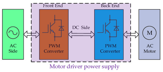
Figure 1.
System structure diagram of motor driver power supply.
In this paper, the circuit topology of reversible three-phase PWM converter at the front end of motor driver power supply adopts neutral point clamped (NPC) I-type three-phase three-level circuit, as shown in Figure 2, which mainly includes the following three parts: AC side, bridge circuit, and DC side. usa, usb, and usc are the phase voltages of the AC side with the midpoint of N; Ls and Rs are the inductance and the equivalent resistance of the AC side, respectively; isa, isb, and isc are the currents at the AC side. Each phase of the three-phase bridge arm is composed of four insulated gate bipolar transistor (IGBT) switches Si1~Si4 (i = a,b,c) with freewheel diodes and two clamping diodes Di1~Di2 (i = a,b,c). Two bus capacitors (Cd1 and Cd2) of the same size are connected in series at the DC side. O is the midpoint of the capacitance, and Udc is the DC bus voltage.
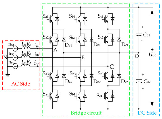
Figure 2.
Main circuit of neutral point clamped (NPC) I-type three-phase three-level pulse width modulation (PWM) converter.
The PWM converter adopts the double closed-loop control structure based on the AC side voltage vector oriented control, including the voltage outer loop and the current inner loop, as shown in Figure 3. The modulation method adopts space vector pulse width modulation (SVPWM). The orientation angle θ calculated by phase-locked loop (PLL) is sent to abc/dq transformation unit and inverse Park transformation (I-Park) unit. Through abc/dq transformation, the mathematical model of the system is transformed from three-phase static ABC coordinate system to dq rotation coordinate system. ud and uq are the voltage components of the d-axis and q-axis, respectively, and id and iq are current components of d-axis and q-axis, respectively. The current components of the d-axis and q-axis are mutually coupled after coordinate transformation. For this reason, the current feed-forward decoupling control strategy is introduced, in which the components ωLsiq and ωLsid of q-axis and d-axis are injected into the d-axis and q-axis forward channels of the current loop, respectively, so that the independent control of the current components of the dq axis can be realized [23].
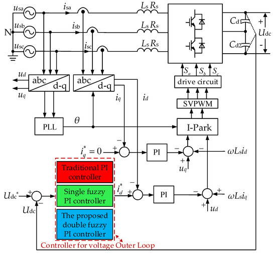
Figure 3.
Double closed-loop control structure of three-phase PWM converter.
The current inner loop is usually designed as a follower with PI controller to follow the current given by the voltage outer loop, and track the voltage phase of the AC voltage through voltage vector-oriented control, so as to realize the unity power factor and sinusoidal current at the AC side [24,25]. In order to realize the stable DC side voltage (Udc) control without static error, it is necessary to design the controller for voltage outer loop, as shown in Figure 3, the voltage outer loop compensator can be implemented by the traditional PI controller, traditional single fuzzy PI controller, and the proposed double fuzzy PI controller in this paper. Different from the current inner loop, the response speed of the voltage outer loop is much slower, and the cut-off frequency of the voltage loop should be far less than that of the current loop [26]. Therefore, when the traditional PI controller is used for system correction, the anti-disturbance performance of the voltage outer loop should be mainly considered [27].
The parameters of PWM converter in Figure 3 are as follows: Rs = 0.002 Ω, Ls = 1 mH, Cd1 = Cd2 = 1475 μF. AC side phase voltage is E = 220 V, the DC side voltage is Udc = 700 V, the power is Po = 16 kW, and the switching frequency is fs = 20 kHz. Bode diagram method is used to design PI parameters of the voltage outer loop with a cut-off frequency of 100 Hz and a phase margin of 45°. Considering the sampling period with digital control, the calculated PI control parameters are kp = 5.587, ki = 0.05892. It is noticed that the parameters of traditional PI controller are the optimal values theoretically under some certain working conditions, which are largely dependent on the mathematical model of some certain operating point. However, with the traditional PI controller, the designed PI control parameters cannot be modified at will [28], even if the traditional single fuzzy PI controller is used in the Figure 3, the PI parameters can only be adaptively changed according to the DC voltage error and its error change rate. So it is difficult for the front-end reversible three-phase PWM converter with a wide range of AC side voltage and DC side voltage to obtain better control performance if the traditional PI controller and the single fuzzy PI controller is used in the voltage outer loop.
Therefore, the double fuzzy PI control method for the voltage outer loop is proposed on the basis of the traditional single fuzzy PI controller, which can adaptively adjust PI parameters to improve the dynamic and static performance of the front-end reversible three-phase PWM converter according to a variety of circumstances. The following will discuss the design method of the double fuzzy PI controller for the voltage outer loop.
3. Analysis and Design Method of the Double Fuzzy PI Controller for Voltage Outer Loop
As shown in Figure 4, the proposed double fuzzy PI controller is implemented by adding a sub fuzzy controller to the traditional fuzzy PI controller, and the sub fuzzy controller outputs the auxiliary correction of PI parameters. Considering the application of a wide range of AC voltage and DC voltage in a reversible three-phase PWM converter, the AC side voltage variation and the DC side given voltage variation are taken as the inputs of the sub fuzzy controller, and the outputs of the sub fuzzy controller is designed as the auxiliary correction of the PI parameters of the voltage outer loop; the traditional fuzzy PI controller presented here is called the main fuzzy controller and outputs the correction of PI control parameters according to the DC voltage error and its error change rate. And the adaptive adjustment of PI control parameters of the voltage outer loop is the sum of the PI parameter correction output by the main fuzzy controller and the auxiliary PI parameter correction output by the sub fuzzy controller. The output of the PI regulator in the Figure 4 serves as the d-axis current given signal id* of current inner loop, and G(s) is the transfer function from the d-axis current to the DC voltage Udc.
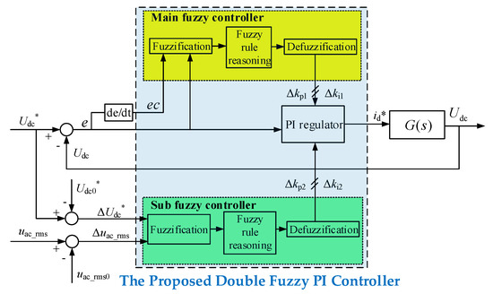
Figure 4.
The block diagram of voltage outer loop with the proposed double fuzzy PI controller.
The inputs of the main fuzzy controller are the error e between the DC bus given voltage Udc* and the actual DC side voltage Udc, and the error change rate ec. After fuzzification, reasoning by fuzzy rules, and then after defuzzification, a group of correction values of PI control parameters for PI regulator, Δkp1 and Δki1 are obtained; the inputs of the sub fuzzy controller are the change of the effective value of AC phase voltage Δuac_rms and the change of the DC given voltage ΔUdc*. Through the same working procedure as the main fuzzy controller, another group of correction values of PI control parameters, Δkp2 and Δki2 are obtained and here defined as auxiliary correction of PI parameters for PI regulator. Adding the above two groups of PI parameter corrections correspondingly to get the sums, i.e., Δkp1 + Δkp2 and Δki1 + Δki2, then adding these sums to the previous values of PI parameters, the current values of PI parameters kp and ki are calculated.
3.1. Design of Main Fuzzy Controller
The structure of the main fuzzy controller is shown in Figure 4. The main design process includes three parts—fuzzification, fuzzy rule reasoning and defuzzification.
3.1.1. Fuzzification
Fuzzification is to convert precise input and output values into fuzzy linguistic values. The concrete implementation steps are as follows:
1) The basic universe of error e between the DC side given voltage Udc* and the sampling Udc, and the basic universe of the corresponding error change rate ec can be obtained by simulation and experiment. Here, the range of error e is [−600, +600], and the range of error change rate ec [−300, +300]. Assuming that the fuzzy universe of error e and error change rate ec is set as [−3, 3], then the two intervals are discretized, and the discrete set is {−3, −2, −1, 0, 1, 2, 3}. Hence, the error e and the error change rate ec can be transformed from the basic universe to the fuzzy universe by the following quantization factor:
The outputs of the main fuzzy controller are a group of correction values, Δkp1 and Δki1, respectively, corresponding to the proportional control parameters and integral control parameters in the PI regulator. The ranges of the two outputs are also obtained by simulation and experiment, here the range of Δkp1 is [−1.5, +1.5], while Δki1 [−7.5 × 10⁻³, +7.5 × 10⁻³]. Assuming that the fuzzy universe of Δkp1 and Δki1 is also set as [−3, 3], the discrete set is {−3, −2, −1, 0, 1, 2, 3}. The following scale factor can be gotten to transform Δkp1 and Δki1 from basic universe to fuzzy universe:
2) Considering that the input voltage error e and error change rate ec, as well as the output Δkp1 and Δki1 can change in positive and negative directions, the fuzzy universe is described by seven linguistic values: “Negative Big (NB),” “Negative Middle (NM),” “Negative Small (NS),” “Zero (ZE),” “Positive Small (PS),” “Positive Middle (PM),” and “Positive Big (PB).” Then, the quantized discrete set {−3, −2, −1, 0, 1, 2, 3} can be described as fuzzy language set {NB, NM, NS, ZE, PS, PM, PB}. The membership function of input and output is defined as a triangular membership function, as shown in Figure 5.
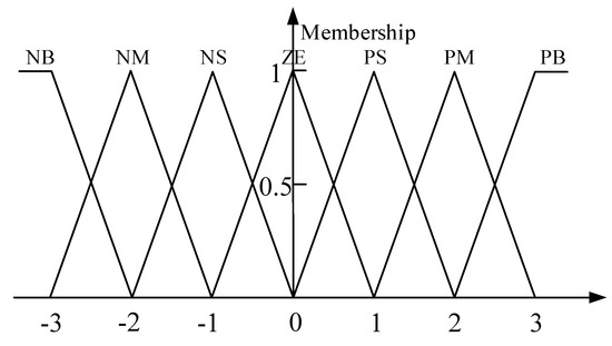
Figure 5.
Triangular membership function of e,ec and Δkp1,Δki1.
Through the above two steps, four precise signals of input and output can be fuzzified and transformed into fuzzy language set.
3.1.2. Fuzzy Rule Reasoning
The design of fuzzy rules of main fuzzy controller will directly affect the parameters of the PI controller and then affect the dynamic and static performance of the PWM converter. In order to obtain better kp and ki through the fuzzy controller, it is necessary to analyze trend of PI parameters with error e and error change rate ec. First, the influence of PI parameters on the dynamic and static performance of the system is analyzed:
- 1)
- Proportional coefficient kp—when kp is small, the response speed of the system is slow, the adjustment time is long, the regulation accuracy is low, and the dynamic and static performance of the system poor; with the increase of kp, the system response speed is accelerated, and the system regulation accuracy is increased, but when kp is too large, the system will produce large overshoot, and the oscillation times will increase, the adjustment time will become longer, and even leading to the system instability in serious cases.
- 2)
- Integral coefficient ki—when ki is small, the output static error of the system is difficult to eliminate, which leads to the low adjustment accuracy of the system; with the increase of ki, the elimination speed of static error of the system is accelerated, but if ki is too large, the system will produce integral saturation at the initial stage of response, causing large overshoot, and even leading to the system oscillating, which will affect the stability of the system [29].
According to the influence of kp and ki on the dynamic and static performance of the system, the fuzzy rule table of the main fuzzy controller is designed. The step response curve is shown in Figure 6. The requirements of PI parameters of the controlled object in different regions are analyzed according to the range of error e and error change rate ec. The analysis is as follows:
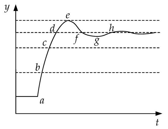
Figure 6.
Step response curve.
- 1)
- ab section—if e and ec are positive big then the larger kp and the smaller ki should be needed in order to achieve faster response speed and suppress occurrence of large overshoot;
- 2)
- bc section—if e is positive medium and ec is positive big, then larger kp, medium ki are selected in order to reach stable value as soon as possible;
- 3)
- cd section—if e changes from positive small value to 0 and ec is positive big, then the larger kp and ki should be selected in order to implement the stability of the system;
- 4)
- de section—if e changes from 0 to negative small value and ec changes from positive big value to 0, then larger kp and medium ki are needed in order to suppress the overshoot;
- 5)
- ef section—if e is from negative small (or negative middle) value to 0 and ec is from 0 to negative middle value, then the smaller kp should be chosen and ki gradually increases from positive middle value to positive big value in order to reduce or prevent secondary oscillation;
- 6)
- fg section—if e is from 0 to positive small (or positive middle) value and ec from negative big value to negative small value, then kp should be increased gradually and ki should be decreased gradually in order to speed up the system response and prevent overshoot;
- 7)
- gh section—if e decreases gradually from positive small (or positive middle) value to 0 and ec decreases slowly, then kp and ki should be increased gradually in order to make the system have good stability.
According to the above analysis, the fuzzy language rule tables of Δkp1 and Δki1 are designed as shown in Table 1 and Table 2, respectively.

Table 1.
Fuzzy language rules of Δkp1.
Table 2.
Fuzzy language rules of Δki1.
Any rule in the fuzzy language rules table of Δkp1 and Δki1 can be expressed in the form of “Ri: if e is Ai and ec is Bi then u is Ci.” Then, the statement of fuzzy language rules table can be expressed as follows:
- 1)
- R1: if e is NB and ec is NB then Δkp1 is PB and Δki1 is NB
- 2)
- R2: if e is NB and ec is NM then Δkp1 is PB and Δki1 is NB
- 3)
- R3: if e is NB and ec is NS then Δkp1 is PB and Δki1 is NB
…
- 49)
- R49: if e is PB and ec is PB then Δkp1 is PB and Δki1 is NB
For the membership function with seven linguistic values corresponding to the two inputs, the total number of the control rules is 7 × 7 = 49. Each fuzzy control rule can give a fuzzy implication relation Ri (i = 1, 2, …, 49). Then, the total fuzzy implication relations corresponding to fuzzy rules are as follows:
3.1.3. Defuzzification
The result of fuzzification and fuzzy reasoning is the fuzzy set of Δkp1 and Δki1, so it is necessary to defuzzify the fuzzy set in order to get a clear and precise values of the correction. Here, the weighted average method is used to defuzzify. For each element xi (i = 1, 2, …, n) in the universe, the membership degree u(i) of the fuzzy set after fuzzification is taken as the weighting coefficient of the corresponding element, and the final decision value xo can be obtained from the following Equation (4):
After defuzzification, Δkp1 and Δki1 are transformed from fuzzy universe to basic universe through the scale factor introduced in Section 3.1.1, and the final actual output value is obtained.
3.2. Design of the Sub Fuzzy Controller
The sub fuzzy controller is designed for the changes of AC voltage and DC given voltage, and the PI parameters can be further adjusted. The main design flow of the sub fuzzy controller is the same as that of the main fuzzy controller, so it will not be explained in detail.
The 16 kW reversible three-phase PWM converter in this paper is developed: the range of the AC phase voltage effective value is 200~240 V (line-to-neutral) and the range of DC side’s given voltage is 650~750 V. In the experimental prototype, the rated AC phase voltage effective value is 220 V, and the rated DC voltage is 700 V. If the rated AC phase voltage effective value of 220 V is taken as the midpoint uac_rms0 of the range of the AC phase voltage effective value, then the basic universe of AC phase voltage effective value variation Δuac_rms is [−20, 20], and if the quantization factor is 0.1, then the fuzzy universe is [−2, 2] and the discrete set is {−2, −1, 0, 1, 2}. The corresponding five-section fuzzy language variables are {NB, NS, ZE, PS, PB}. If the rated DC side voltage value 700 V is taken as the midpoint Udc*, then the basic universe of the DC given voltage variation ΔUdc* is [−50, 50], and if the quantization factor chooses 0.04, then the fuzzy universe is [−2, 2] and the discrete set is {−2, −1, 0, 1, 2}. The corresponding five fuzzy language variables are {NB, NS, ZE, PS, PB}. Here the memberships functions of Δuac_rms and ΔUdc* can choose the same triangular membership function which are shown in Figure 7.
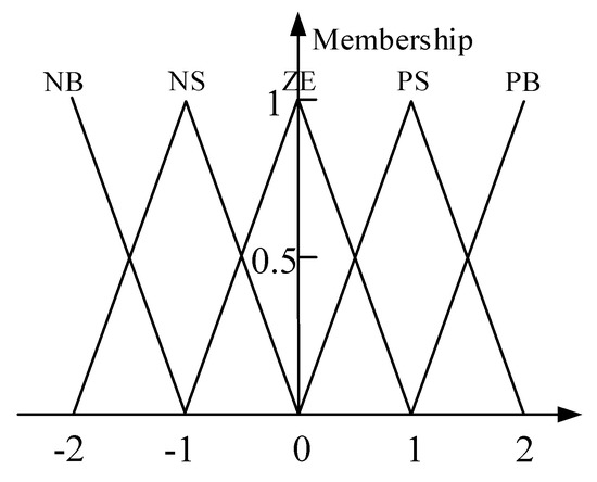
Figure 7.
Triangular membership function of Δuac_rms and ΔUdc*.
Through the design method of the traditional PI controller for the voltage outer loop introduced in Section 2, the optimal PI parameters in the Table 3 and Table 4 can be obtained, respectively, by calculation, simulation, and experiment under different AC voltage and DC given voltage conditions. Udc* is the DC bus given voltage and Uac_rms is the effective value of AC phase voltage.
Table 3.
The optimal value of kp.
Table 4.
The optimal value of ki.
The trend of PI parameters changing with the variation of AC voltage and DC given voltage can be found in Table 3 and Table 4. As a consequence, the fuzzy rules table of output value Δkp2 and Δki2 can be deduced as shown in Table 5 and Table 6. Δuac_rms is the change of the effective value of AC phase voltage and ΔUdc* is the change of the DC given voltage.
Table 5.
Fuzzy language rules of Δkp2.
Table 6.
Fuzzy language rules of Δki2.
If the basic universe of Δkp2 is defined as [−1, 1] and the scale factor is 0.5, then the fuzzy universe is [−2, 2], the corresponding discrete set is {−2, −1, 0, 1, 2}, and the corresponding five fuzzy language variables are {NB, NS, ZE, PS, PB}. If the basic universe of Δki2 is defined as [−10−3, 10−3] and the scale factor is 0.5 × 10⁻³, then the fuzzy universe is [−2, 2], the corresponding discrete set is {−2, −1, 0, 1, 2}, and the corresponding five fuzzy language variables are {NB, NS, ZE, PS, PB}. Here, the triangular membership functions of Δkp2 and Δki2 are the same as that of the input values in Figure 7. Reasoning based on the fuzzy rules in Table 5 and Table 6, the output fuzzy language variables Δkp1 and Δki1 can be obtained. As with the main fuzzy controller, the weighted average method is used to defuzzify. After defuzzification the actual auxiliary correction of PI control parameters Δkp2 and Δki2 are obtained through the precision with the scale factor.
Finally, the auxiliary correction values of PI control parameters Δkp2 and Δki2 obtained by the sub fuzzy controller are added to the correction values of PI parameter Δkp1 and Δki1 obtained by the main fuzzy controller, respectively, and we can get the sums. Then, these sums are added to the previous values kp0 and ki0 of PI parameter, respectively, so we can obtain the current PI parameters kp and ki as shown in Equation (5).
4. Analysis of Experimental Results
4.1. Experiment for Sudden Change of the Load
The 16 kW reversible three-phase PWM converter was built as the front-end converter of the motor driver power supply, as shown in Figure 8. The experimental prototype consists of AC side board, DC side board, control board, bus capacitor board and bridge circuit board. NPC-I type three-phase three-level PWM bridge structure, as shown in Figure 2, was chosen for the bridge circuit board, a DSP TMS320F28335 was employed from TI Company (Texas Instruments, Inc, Dallas, TX, USA) in the control board, and FZ06NIA075SA was chosen from Vincotech Company (Munich, Bayern, Germany) for the three-phase three-level PWM bridge circuit. In this experimental prototype, the PWM converter adopts the double closed-loop control strategy based on the AC side voltage vector oriented control, as shown in Figure 3.
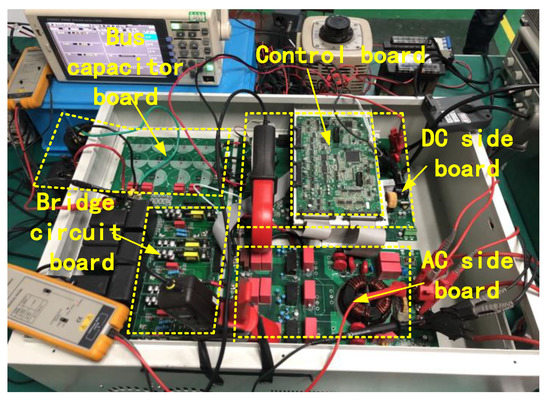
Figure 8.
Experimental prototype of 16 kW reversible three-phase three-level PWM converter.
The parameters of the experimental prototype are as follows: the AC side inductance is 1 mH, the switching frequency is 20 kHz, and the AC voltage frequency is 50 Hz. The DC side voltage of the prototype supply the back-end PWM converter of the motor driver power supply, and the load of the driver power supply is servo motor. According to the law of conservation of energy in the dynamic process, the response time Tr of the voltage outer loop and the maximum variation of the power ΔPmax are considered in the design of DC side capacitance. The change of energy ΔW on capacitance is calculated by Equation (6).
The variation of DC side voltage ΔUdc is as follows:
The DC voltage fluctuation in Equation (7) should be less than the maximum allowable value ΔUdcmax, so Equation (8) is obtained:
When ΔPmax is set as 10% of the rated power, the voltage loop response time Tr is 200 ms and bus voltage fluctuation is 5%. The DC side capacitance can be calculated by Equation (8). Through calculation and comprehensive consideration, the design result of DC side capacitance is 2950 uF.
The rated operating condition of the front-end PWM converter is 220 V AC side phase voltage and 700 V DC bus voltage. Under the rated condition, the experiment of sudden loading and unloading is carried out for the reversible three-phase PWM converter with traditional PI controller and single fuzzy PI controller for the voltage outer loop respectively. The waveforms are shown in Figure 9. In Figure 9, CH1 is A-phase current waveform isa, CH2 is A-phase voltage waveform usa, CH3 is C-phase current waveform isc, and CH4 is DC bus voltage Udc waveform. Figure 9a shows the waveforms using traditional PI controller for voltage outer loop, and Figure 9d shows the waveform using traditional single fuzzy PI controller for voltage outer loop. Figure 9b,c,e,f shows the details of the waveforms when the load changes. For these two kinds of voltage controller, when sudden change of the load is from null load to half load, DC bus voltage was dropped and can be restored to the given voltage value after a short period of adjustment; while sudden change of the load is from half load to null load, the DC bus voltage overshot and can be restored to the given DC voltage value after a short period of adjustment. The experimental data of traditional PI controller and single fuzzy PI controller used in the voltage outer loop are shown in Table 7. From the Figure 9 and Table 7, it can be seen that the reversible three-phase PWM converter with traditional single fuzzy PI controller used in the voltage outer loop has smaller overshoot and drop, and faster dynamic response speed than the traditional PI controller.
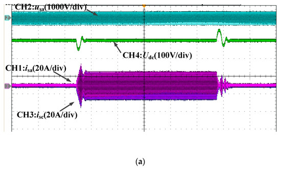
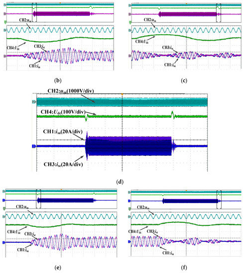
Figure 9.
Waveforms adopting traditional PI controller and single fuzzy PI controller respectively for voltage outer loop (AC: 220 V, DC: 700 V). (a) Waveforms adopting traditional PI controller; (b) zoom in of waveform under sudden load (traditional PI controller); (c) zoom in of waveform under sudden unload (traditional PI controller); (d) waveforms adopting single fuzzy PI controller; (e) zoom in of waveforms under sudden load (single fuzzy PI controller); (f) zoom in of waveforms under sudden unload (single fuzzy PI controller).
Table 7.
Comparison of experimental data with traditional PI controller and single fuzzy PI controller, respectively.
In view of the wide AC side and wide DC side voltage application range, the corresponding maximum and minimum values of AC side voltage and DC side given voltage were selected respectively, and the experiments for sudden change of the load using double fuzzy PI controller and traditional single fuzzy PI controller respectively were compared. Under the operating condition that the AC phase voltage is 200 V and the DC bus voltage is 650 V, the experiment of sudden loading and unloading is carried out for the reversible three-phase PWM converter with traditional single fuzzy PI controller and double fuzzy PI controller for the voltage outer loop respectively. The waveforms are shown in Figure 10. Under the operating condition that the AC phase voltage is 240 V and the DC bus voltage is 750 V, the same experiments were carried out. The waveforms are shown in Figure 11. The channels of the same physical quantity in Figure 10 and Figure 11 are the same as above. The experimental data of traditional single fuzzy PI controller and double fuzzy PI controller used in the voltage outer loop are shown in Table 8. From the Figure 10 and Figure 11 and Table 8, it can be seen that the reversible three-phase PWM converter with double fuzzy PI controller has smaller overshoot and drop and faster dynamic response speed than that with traditional single fuzzy PI controller. It can be seen that the performance using double fuzzy PI controller is much better than that using traditional single fuzzy PI controller when the AC voltage and DC given voltage changed in large range. The results of the experiment verify the effectiveness of the proposed double fuzzy PI controller in this paper.
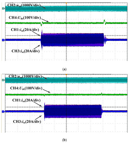
Figure 10.
Waveforms adopting traditional single fuzzy PI controller and double fuzzy PI controller respectively for voltage outer loop (AC: 200 V, DC: 650 V). (a) Waveforms adopting traditional single fuzzy PI controller; (b) waveforms adopting double fuzzy PI controller.
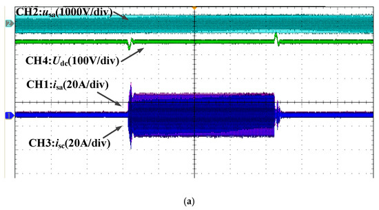
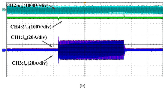
Figure 11.
Waveforms adopting traditional single fuzzy PI controller and double fuzzy PI controller respectively for voltage outer loop (AC: 240 V, DC: 750 V). (a) Waveforms adopting traditional single fuzzy PI controller; (b) waveforms adopting double fuzzy PI controller.
Table 8.
Comparison of experimental data with single fuzzy PI controller and double fuzzy PI controller, respectively.
The selection of DC side capacitance should be considered. On the one hand, the larger the value of DC side capacitance, the better the filtering effect; on the other hand, considering the volume, weight, price, and dynamic characteristics, the value of DC side capacitance should not be too large. Therefore, two capacitances with different values are used for comparison. Figure 11b shows waveforms adopting double fuzzy PI controller with the 2950 μF DC side capacitance. Figure 12 shows waveforms adopting double fuzzy PI controller with the 1600 μF DC side capacitance. The experimental data of adopting 2950 μF and 1600 μF DC side capacitances with double fuzzy PI controller are shown in Table 9. Figure 11b and Table 9 show that using smaller DC side capacitance can make the dynamic response of the system faster.
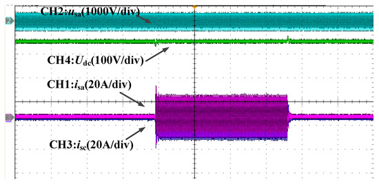
Figure 12.
Waveforms adopting double fuzzy PI controller with the 1600 μF DC side capacitance.
Table 9.
Comparison of experimental data of adopting double fuzzy PI controller with different DC side capacitances.
4.2. Practical Application of Double Fuzzy PI Controller
The experimental prototype is used as the front-end PWM converter of the motor driver power supply, and the voltage outer loop of experimental prototype adopts the proposed double fuzzy PI controller. The sinusoidal speed signal is given to the motor load of the driver power supply, the period of given sinusoidal speed signal is 5 s, and its peak value corresponds to the given value of the maximum speed. The waveforms are shown in Figure 13.
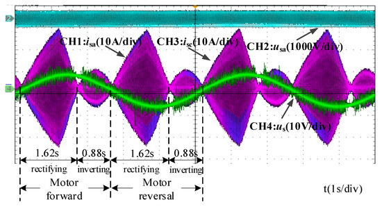
Figure 13.
Experimental waveforms with sinusoidal speed given signal.
In Figure 13, Channels CH1 and CH3 are A-phase current and C-phase current waveforms, respectively; CH2 is A-phase voltage waveform; and CH4 is the sinusoidal speed given signal. Observe the waveform of a sinusoidal cycle. The converter works in the rectifier state first. At this time, the motor rotates forward and accelerates with the given sinusoidal speed signal. Due to the existence of rotation inertia, the motor starts to decelerate at 1.62 s (instead of 1.25 s corresponding to the peak of voltage signal). At this time, the converter switches to the inverter state and feeds back the energy generated by motor decelerating to the AC side. When the motor reverses, its operating principle is the same as that of forward rotation. It can be seen that the proposed double fuzzy PI controller can achieve good performance when used in a reversible PWM converter with a wide range of AC side voltage and DC side voltage.
5. Conclusions
The double fuzzy PI controller for the voltage outer loop of the reversible three-phase PWM converter is proposed in this paper. This method not only does not depend on the precise model of the control object but can also adjust the PI control parameters adaptively, which is equivalent to changing the static operating point of the control object under specific operating conditions, making the system adaptive to a new balance point. On the basis of the traditional fuzzy PI controller, the double fuzzy PI controller is realized by adding the sub fuzzy controller, which generates the auxiliary correction of PI parameters due to the AC side voltage variation and DC side given voltage variation of the reversible three-phase PWM converter. Therefore, the proposed double fuzzy PI controller can realize the stable control of the reversible three-phase PWM converter with wide AC side voltage and DC side voltage, and obtain fast dynamic response performance. In future work, we will apply the design idea of the double fuzzy controller in this paper to the control of the back-end inverter of the motor driver power supply in order to realize the universality of the motor driver.
Author Contributions
Conceptualization, W.Z. and Y.F.; Methodology, W.Z.; Software and investigation, R.Y. and Y.F.; Validation, Z.W. and W.Z.; Formal analysis, Y.F. and Z.W.; Writing—review and editing, W.Z. and R.Y. All authors have read and agreed to the published version of the manuscript.
Funding
Supported by the Equipment Pre-research Project of China (No.31512040201-2) and supported by the Science and Technology Cooperation Fund of Yangzhou City Hall project (No. YZ2018136).
Conflicts of Interest
The authors declare no conflict of interest.
Nomenclature
| PWM | Pulse Width Modulation |
| PI | Proportional Integral |
| IGBT | Insulated Gate Bipolar Transistor |
| NPC | Neutral Point Clamped |
| SVPWM | Space Vector Pulse Width Modulation |
| PLL | Phase-Locked Loop |
| I-Park | Inverse Park Transformation |
References
- Jung, J.; Ku, H.; Son, Y.; Kim, J. Open-switch fault diagnosis algorithm and tolerant control method of the three-phase three-level NPC active rectifier. Energies 2019, 12, 2495. [Google Scholar] [CrossRef]
- Lee, T.-S.; Kune-Shiang, T. Input-output linearizing control with load estimator for three-phase AC/DC voltage-source converters. In Proceedings of the 2002 IEEE 33rd Annual IEEE Power Electronics Specialists Conference, Cairns, Australia, 23–27 June 2002; pp. 791–795. [Google Scholar]
- Han, Z.; Wang, X.; Jiang, B.; Chen, J. A Control strategy for suppressing zero-sequence circulating current in paralleled three-phase voltage-source PWM converters. Appl. Sci. 2020, 10, 1703. [Google Scholar] [CrossRef]
- Vujacic, M.; Hammami, M.; Srndovic, M.; Grandi, G. Analysis of dc-link voltage switching ripple in three-phase PWM inverters. Energies 2018, 11, 471. [Google Scholar] [CrossRef]
- Li, Z.Q.; Cheng, W.Y.; Xiao, Q.H.; Liao, W.X. Deadbeat predictive power control with fuzzy PI compound controller and power predictive corrector for PWM rectifier under unbalanced grid conditions. Int. J. Fuzzy Syst. 2020, 22, 1277–1288. [Google Scholar] [CrossRef]
- Zhang, M.; Cui, Y.; Wang, Q.; Tao, J.; Wang, X.; Zhao, H.; Li, G. A study on neutral-point potential in three-level NPC converters. Energies 2019, 12, 3367. [Google Scholar] [CrossRef]
- Wang, B.; Tang, Y.; Zhang, L. Research on voltage fuzzy adaptive control of PWM rectifier in synchronous coordinate. In Proceedings of the 3rd IEEE International Conference on Electronic Information Technology and Computer Engineering (EITCE), Xiamen, China, 18–20 October 2019; pp. 519–522. [Google Scholar]
- Lin, H.; Leon, J.I.; Luo, W.; Marquez, A.; Liu, J.; Vazquez, S.; Franquelo, L.G. Integral sliding-mode control-based direct power control for three-level NPC converters. Energies 2020, 13, 227. [Google Scholar] [CrossRef]
- Jamma, M.; Bennassar, A.; Akherraz, M.; Fahassa, C.; Barara, M.; Oproescu, M. Self-Tuning fuzzy PI dc-Bus voltage controller and fuzzy switching sequences selection for direct power control of PWM AC/DC converter. In Proceedings of the 9th International Conference on Electronics, Computers and Artificial Intelligence (ECAI), Targoviste, Romania, 29 June–1 July 2017; pp. 1–6. [Google Scholar]
- Hafsi, S.; Dhaoui, M.; Lassaad, S. Fuzzy logic control of grid-connected PWM rectifiers with LCL filters. In Proceedings of the 2017 IEEE International Conference on Green Energy and Conversion Systems, Hammamet, Tunisia, 23–25 March 2017. [Google Scholar]
- Juang, C.F.; Lu, C.F. Load-frequency control by hybrid evolutionary fuzzy PI controller. IET Gener. Transm. Distrib. 2006, 153, 196–204. [Google Scholar] [CrossRef]
- Yan, Q.Z.; Wu, X.J.; Yuan, X.B.; Geng, Y.W. An improved grid-voltage feedforward strategy for high-power three-phase grid-connected inverters based on the simplified repetitive predictor. IEEE Trans. Power Electron. 2016, 31, 3880–3897. [Google Scholar] [CrossRef]
- Lu, M.H.; Frede, B. Stability identification for grid-connected inverters with LCL filters considering grid-voltage feedforward regulator. In Proceedings of the 2017 IEEE 18th Workshop on Control and Modeling for Power Electronics (COMPEL), Stanford, CA, USA, 9–12 July 2017; pp. 1–5. [Google Scholar]
- Zhao, R.T.; Chang, Z.G.; Yuan, P.E.; Yang, L.Y.; Li, Z.X. A novel fuzzy logic and anti-windup PI controller for three-phase grid connected inverter. In Proceedings of the 2009 2nd International Conference on Power Electronics and Intelligent Transportation System (PEITS), Shenzhen, China, 19–20 December 2009; pp. 442–446. [Google Scholar]
- Ahmed, K.Y.; Yahaya, N.Z.; Asirvadam, V.S.; Ramani, K.; Ibrahim, O. Comparison of fuzzy logic control and PI control for a three-level rectifier based on voltage oriented control. In Proceedings of the 6th IEEE International Conference on Power and Energy (PECON), Melaka, Malaysia, 28–29 November 2016; pp. 127–132. [Google Scholar]
- Zeb, K.; Islam, S.U.; Din, W.U.; Khan, I.; Ishfaq, M.; Busarello, T.D.C.; Ahmad, I.; Kim, H.J. Design of fuzzy-PI and fuzzy-sliding mode controllers for single-phase two-stages grid-connected transformerless photovoltaic inverter. Electronics 2019, 8, 520. [Google Scholar] [CrossRef]
- Kumar, M.; Singh, B.; Singh, B.P. Fuzzy pre-compensated PI controller for PMBLDC motor drive. In Proceedings of the 2006 International Conference on Power Electronic, Drives and Energy Systems, New Delhi, India, 12–15 December 2006; pp. 1–5. [Google Scholar]
- Azli, N.A.; Wong, S.N. Development of a DSP-based fuzzy PI controller for an online optimal PWM control scheme for a multilevel inverter. In Proceedings of the 2005 International Conference on Power Electronics and Drives Systems, Kuala Lumpur, Malaysia, 28 November–1 December 2005; pp. 1457–1461. [Google Scholar]
- Lee, J.H. On methods for improving performance of PI-type fuzzy logic controllers. IEEE. Trans. Fuzzy Syst. 1993, 1, 298–301. [Google Scholar]
- Zheng, Z.; Tao, H.J. Research of three-phase PWM rectifier based on PI control with auto-tuning scaling factors. In Proceedings of the 6th World Congress on Intelligent Control and Automation, Dalian, China, 21–23 June 2006; pp. 3844–3847. [Google Scholar]
- Liu, G.Q.; Li, L. Quantification factor self-tuning fuzzy PID controller research for a permanent magnet synchronous motor feeding system. In Proceedings of the 24th Chinese Control and Decision Conference (CCDC), Taiyuan, China, 23–25 May 2012; pp. 2510–2514. [Google Scholar]
- Singh, P.D.; Sharma, A.; Gao, S. PWM based AC-DC-AC converter for an Isolated hydro power generation with variable turbine input. In Proceedings of the 2018 2nd International Conference on Power, Energy and Environment (ICEPE), Shillong, India, 1–2 June 2018; pp. 1–6. [Google Scholar]
- Huang, J.; Yuan, X.M. Impact of the voltage feed-forward and current decoupling on VSC current control stability in weak grid based on complex variables. In Proceedings of the 2015 IEEE Energy Conversion Congress and Exposition (ECCE), Montreal, QC, Canada, 20–24 September 2015; pp. 6845–6852. [Google Scholar]
- Lakshmi, M.B.; Thangasankaran, R.; Gnanavadivel, J.; Christa, S.T.J. Performance evaluation of fuzzy controlled single phase PWM rectifier. In Proceedings of the 2nd International Conference on Electronics, Communication and Aerospace Technology (ICECA), Coimbatore, India, 29–31 March 2018; pp. 1974–1979. [Google Scholar]
- Khairy, A.; Ibrahim, M.; Abdel-Rahim, N.; Elsherif, H. Comparing proportional-resonant and fuzzy-logic controllers for current controlled single-phase grid-connected PWM DC/AC inverters. In Proceedings of the IET Conference on Renewable Power Generation (RPG), Edinburgh, UK, 6–8 September 2011; pp. 1–6. [Google Scholar]
- Hoang, T.T.G.; Wang, X.H.; Zhou, X.Z.; Tian, L.F.; Chen, W.C. Fractional proportional integral controller applied into two parallel 3-phase PWM rectifiers. In Proceedings of the 2017 IEEE 2nd Advanced Information Technology, Electronic and Automation Control Conference (IAEAC), Chongqing, China, 25–26 March 2017; pp. 9–13. [Google Scholar]
- Han, Q.; Li, B.; Li, Z.; Ke, Q. Research of grid-connected photovoltaic inverter grid-connected system based on dual closed-loop of grid voltage vector orientation. In Proceedings of the 2017 Chinese Automation Congress (CAC), Jinan, China, 20–22 October 2017; pp. 5171–5176. [Google Scholar]
- Dyhia, K.; Hakim, D.; Lamine, H.M.; Arezki, F.; Nacereddine, B. Comparative study of PI and fuzzy logic controllers for three-phases parallel multi-cell converter. In Proceedings of the 2019 International Conference on Control, Automation and Diagnosis (ICCAD), Grenoble, France, 2–4 July 2019; pp. 1–5. [Google Scholar]
- Pivonka, P. Comparative analysis of fuzzy PI/PD/PID controller based on classical PID controller approach. In Proceedings of the 2002 IEEE World Congress on Computational Intelligence, Honolulu, HI, USA, 12–17 May 2002; pp. 541–546. [Google Scholar]


© 2020 by the authors. Licensee MDPI, Basel, Switzerland. This article is an open access article distributed under the terms and conditions of the Creative Commons Attribution (CC BY) license (http://creativecommons.org/licenses/by/4.0/).