Article

Improved Interface Circuit for Enhancing the Power Output of a Vibration-Threshold-Triggered Piezoelectric Energy Harvester

1
School of Electronics and Information, Soochow University, Suzhou 215006, China
2
Shanghai Institute of Microsystem and Information Technology, Chinese Academy of Sciences, Shanghai 200050, China
*
Author to whom correspondence should be addressed.
Energies 2020, 13(15), 3830; https://doi.org/10.3390/en13153830
Submission received: 29 June 2020 / Revised: 20 July 2020 / Accepted: 21 July 2020 / Published: 25 July 2020
(This article belongs to the Section L: Energy Sources)

Abstract

:
The vibration-threshold-triggered piezoelectric energy harvester is a new type of piezoelectric energy harvester with a two-stage structure, which can generate electricity in a low frequency environment and recognize vibration intensity at the same time. In this study, a theoretical model of a vibration-threshold-triggered energy harvester was examined, and an equivalent circuit model of the energy harvester was obtained. Then, an interface circuit was proposed that can significantly improve the output power of the energy harvester. The interface circuit achieved impedance matching with the piezoelectric material to maximize the energy collected from the energy harvester. First, we calculated and analyzed the impedance characteristics of the energy harvester, based on the equivalent circuit model. It was found that because the piezoelectric material is in resonance as the energy harvester is in operation, the corresponding impedance is almost resistance. Therefore, a resistance-matching strategy was proposed. Last, we proposed an interface circuit with adjustable input impedance to achieve resistance matching. The experimental results show that the proposed interface circuit can increase the output power of the energy harvester by 48.1–55.7% over that achieved with the standard interface circuit.

1. Introduction

The study of wireless sensor nodes has made great progress in recent years, accompanied by the rapid development of Internet of Things technology. However, the power supply problem remains a limiting factor in the development of wireless sensor nodes. The traditional method, using a battery, is expensive, and in most cases, it is not easy to replace the battery with one that meets the design requirements of the wireless sensor node. It is effective to use energy from the environment to power wireless sensor nodes, so energy harvesters that convert energy that is present in the environment into electrical energy are attracting increased attention [1,2].
Vibration is a common phenomenon in nature, and it exists in almost every corner of our world. Converting vibration energy into electrical energy is a new research hotspot [3,4]. Typically, vibration energy harvesters are classified as electrostatic [5], piezoelectric [6], triboelectric [7], and electromagnetic [8]. Among these, piezoelectric vibration energy harvesters are increasingly being used to power sensor nodes, due to their simple operation and high energy density. Many recent reports focus on piezoelectric energy harvesters. For example, the indirect impact-based piezoelectric vibration energy harvester proposed by Ju and Ji has a maximum open-circuit voltage of 42.2 V peak to peak and an average power of 633.7 μW at 3 g acceleration and 17 Hz [9]. Guan and Liao presented a piezoelectric energy harvester for use in rotational motion that achieves a power output of 83.5–825 μW at rotational frequencies of 7–13.5 Hz [10].
Piezoelectric energy harvesters most commonly have the form of a single cantilever beam. A piezoelectric energy harvester with this structure has its highest power generation efficiency where the excitation frequency is equal to the resonance frequency of the harvester. This makes the operating frequency band narrow [11,12]. In recent years, more and more broadband piezoelectric energy harvesters have been introduced [13,14]. For example, Fan et al. proposed a monostable piezoelectric energy harvester that increases the operating bandwidth by 54% and the output power by 253% relative to a linear piezoelectric energy harvester [15]. Zhang and Qin presented a tunable frequency up-converting wideband piezoelectric vibration energy harvester, using a novel impact-rope-driven hybrid mechanism, with a central working frequency that can be easily changed from 74.75 to 106 Hz [16].
Tang et al. proposed an event-driven vibration-threshold-trigger piezoelectric energy harvester [17]. This energy harvester has a two-stage structure, adopting a mechanism of frequency up-conversion by magnetic coupling and identifying vibration intensity while generating electric energy. When the vibration intensity exceeds the threshold, the energy harvester begins efficient electricity generation. These characteristics greatly simplify the design of the wireless sensor node. He et al. developed a wireless sensor node based on this energy harvester that can identify the type of vibration [18]. The vibration-threshold-trigger piezoelectric energy harvester they used can identify the vibration intensity and act as a sensor while harvesting energy. Therefore, the sensor node does not require complex signal transmission links using sensors and ADCs (Analog-to-Digital Converters). These systems can be simplified, and the energy requirements of the entire system can be reduced. However, the problem of maximizing the output power of the energy harvester remains little studied.
The output power of a piezoelectric energy harvester is usually small, and it cannot supply power directly to the sensing nodes, so the interface circuit for energy harvesting is an important part of the wireless sensing node. A standard energy-harvesting interface circuit is used in the sensor node designed by He et al. [18], which converts the AC voltage generated by the vibration-threshold-triggered energy harvester to DC voltage with an AC–DC rectifier and then stores the harvested energy in the storage capacitor. However, this type of interface circuit cannot maximize the energy harvested. Many studies have attempted to improve the output power of piezoelectric energy harvesters with interface circuit designs, such as synchronized switch harvesting on inductor (SSHI) [19] circuits and synchronous electric charge extraction (SECE) [20] circuits. SSHI circuits are designed to extract electric energy in the inherent capacitance of the piezoelectric energy harvester by minimizing the time during which the inherent capacitance is charged and discharged, and the harvested power is more than 900% greater with this circuit than with the standard interface circuit. The SECE circuit also extracts electrical energy in its inherent capacitance, which can increase energy-harvesting efficiency by 400%. It should be noted that both methods require precise timing for the control of the switch. The SSHI circuit must have its switch flipped when the output voltage amplitude is at the maximum, while the power-extraction phase of the SECE circuit is synchronized with mechanical vibration. This indicates that these two methods can significantly increase the output power of the piezoelectric energy harvester, but due to the precise timing requirements, the control circuit is very complex [21,22,23,24]. The vibration-threshold-triggered piezoelectric energy harvester has a relatively small size (about 14 mm × 21 mm), so its output power is limited, and it is difficult to separate the excess power to drive the control circuit. Another way to increase the output power of a piezoelectric energy harvester is to match load impedance to source impedance. For example, Chen et al. proposed an interface circuit to achieve the impedance matching of impact-type micro wind piezoelectric energy harvesters, which can significantly improve harvesting power [25,26,27].
In this paper, we model and analyze a vibration-threshold-triggered piezoelectric energy harvester, study an equivalent circuit model, and obtain a single-degree-of-freedom equivalent circuit model of the harvester. Using the equivalent circuit model, the impedance characteristics of the energy harvester are calculated and analyzed. Finally, an interface circuit based on the impedance-matching principle is designed for the vibration-threshold-triggered piezoelectric energy harvester. Experiments are conducted to compare the proposed interface circuit with the standard energy-harvesting interface circuit used in He’s work [18]. The results show that the energy-harvesting power is significantly improved when the proposed interface circuit is used under the same conditions as for the standard circuit.

2. Vibration-Threshold-Triggered Piezoelectric Energy Harvester

2.1. Structure and Operating Principles of the Vibration-Threshold-Triggered Energy Harvester

Figure 1 shows the structure and working principles of the vibration-threshold-triggered energy harvester. The structure of the harvester is given in Figure 1a,b. The U-shaped copper micro-cantilever (sensing stage) with a mass at the tip can respond to low-frequency vibrations (<100 Hz) in the environment. A piezoelectric copper cantilever (generating stage) is in the sensing stage, with a lead–zirconate–titanate (PZT) piezoelectric thin film bonded on the top surface, which has a higher resonant frequency (>100 Hz) and can be used for resonant electric-power generation. Two magnets are mounted at the ends of the sensing stage and the generating stage. They are oriented in the same direction and mutually repelled so that the two stages mechanically couple with each other via the repelling force between the two magnets.
Figure 1c shows the operating principles of the vibration-threshold-triggered piezoelectric energy harvester. For weak vibration, the sensing stage cannot overcome the repulsive magnetic force between the two stages to drive the generating stage into resonance. As a result, it produces only a very weak vibration near its equilibrium point and has an extremely low power output. With an increase in vibration strength, the vibration amplitude of the sensing stage grows larger and larger until it reaches a critical point, where the magnetic repulsive force between the two stages can be overcome. Once the vibration strength surpasses the threshold, the movement of the sensing stage passes into the generating stage and triggers it into high-frequency resonance. That causes a high power output. As is phase-by-phase analyzed in Figure 2, the detailed movement procedure during one stroke of the sensing stage can be decomposed into three phases for better understanding. In Phase 1, driven by the external vibration, the sensing stage starts to move. In Phase 2, when the magnet in the sensing stage approaches the magnet in the generating stage, the magnetic repulsive force pushes the cantilever of the generating stage into bending. In Phase 3, only when the elastic restoring force of the bent cantilever exceeds the magnetic force, the generating stage can be set free to vibrate at its resonant frequency.
When the energy harvester is applied to sensing/monitoring systems, the energy harvester itself can act as a vibration threshold sensor, which can replace the signal conditioning/processing circuit, greatly reducing the complexity of the system and its energy consumption.

2.2. Modeling of the Vibration-Threshold-Triggered Energy Harvester

2.2.1. Vibration Model

Analyses and modeling of the vibration-threshold-triggered piezoelectric energy harvester allows us to understand its output characteristics in different excitation conditions, and at the same time, we can derive an equivalent circuit model to make it easier for us to design interface circuits to improve the output power of the harvester. As shown in Figure 3, each stage of the energy harvester can be considered to be an electromechanical coupling spring-mass-damper resonator, and there is an interaction mechanism between the two stages [17].
For the U-shaped cantilever in the sensing stage, it is subject to the magnetic force between the two stages and inertial force caused by external vibration. The vibration model can be expressed as
M S r ¨ S + D S r ˙ S + K S r S = F b a s e 1 F m ,
where rS, M S , D S , and K S are the displacement, mass, damping coefficient, and stiffness of the sensing stage, respectively. F b a s e 1 = M S a b a s e represents the inertial force caused by external vibration, and a b a s e is the acceleration of the basement. F m is the z-component of the magnetic repulsive force between the magnets mounted individually at the ends of the two stages.
The two stages are both fixed to the same frame. The generating stage is also subject to the magnetic force between the two stages and the inertial force caused by external vibration. In addition, there is a piezoelectric coupling effect in the generating stage. Thus, the equations of motion can be expressed as
M G r ¨ G + D G r ˙ G + K G r G θ G v = F b a s e 2 + F m F m ,
where r G , M G , D G , and K G are the displacement, mass, damping coefficient, and stiffness of the generating stage, respectively. θ G is the piezoelectric coupling factor, and v is the output voltage across the load resistor. F b a s e 2 = M G a b a s e indicates the inertial force applied to the generating stage. Due to there being no mass at the tip of the generating stage, M G is relatively small, so F b a s e 2 is ignored here.
With a load connected to the piezoelectric material, the electrical part can be expressed by the Kirchhoff current equation as
θ G r ˙ G + C p v ˙ + v R L = 0 ,
where R L is the load resistance of the energy harvester. C p represents the inherent capacitance of the piezoelectric material.

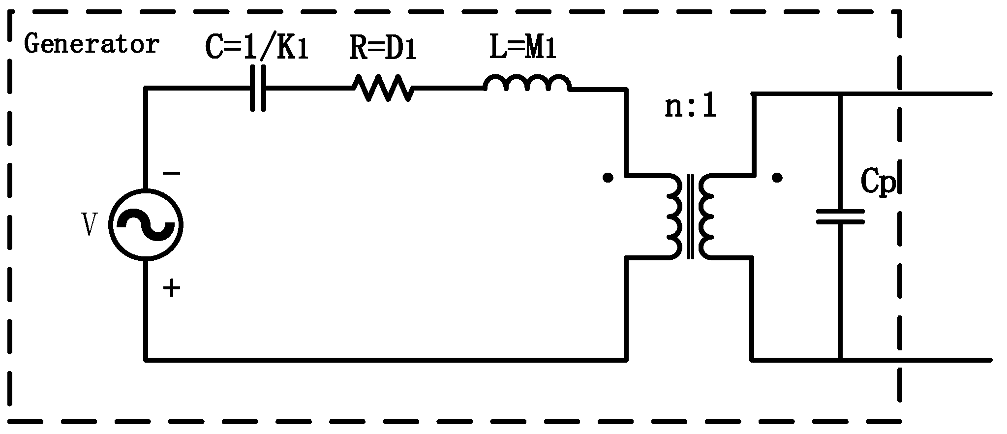
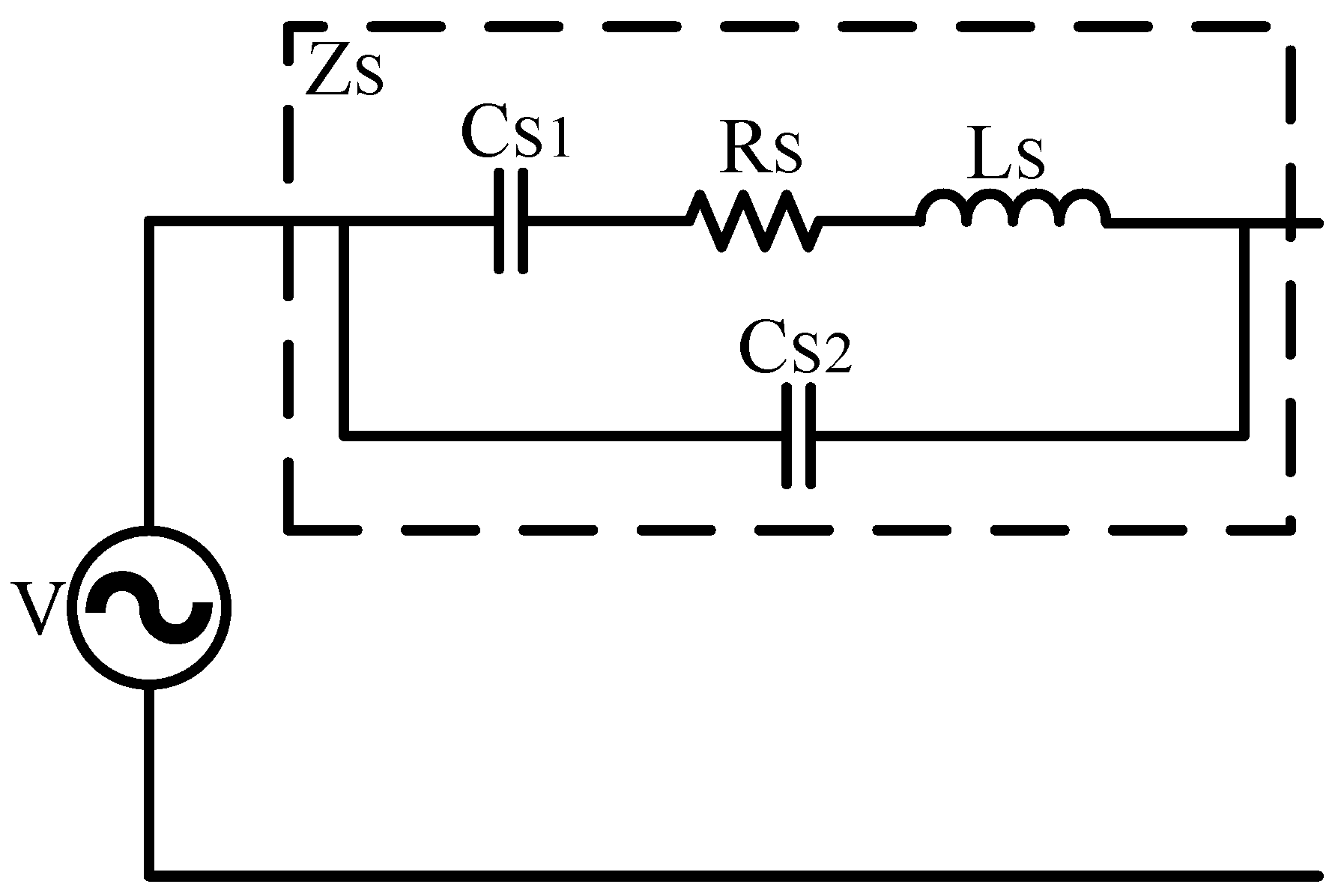
2.2.2. Equivalent Circuit Model

The generating stage forms the power generation structure of the vibration-threshold-triggered energy harvester, and the main function of the sensing stage is to respond to low-frequency vibration to trigger the generating stage to efficiently produce electrical energy when the vibration strength is over the threshold. Because the purpose of this paper is to increase the output power of the energy harvester, it is only necessary to establish an equivalent circuit model of the generating stage. According to the obtained model of the generating stage in Equations (2) and (3), the mechanical and electrical parts of the generating stage can be modeled as electrical components, and the electromechanical coupling can be replaced by an ideal transformer [7]. The single-degree-of-freedom equivalent circuit model obtained is shown in Figure 4.
In this model, the voltage generator V represents the effective force acting on the generating stage, which is provided by the magnetic force between the two stages. The equivalent inductance L = M 1 represents the equivalent mass of the first mode, the resistance R = D1 represents the mechanical damping, and the capacitance C = 1 / K 1 represents the reciprocal of the stiffness. Electromechanical coupling is equivalent to a transformer, where the turn ratio n represents the piezoelectric coupling coefficient θ1, and C p is the intrinsic capacitance of the piezoelectric material.

2.3. Parameter Calculation of Vibration Model

First, we analyze and model the equivalent parameters of the piezoelectric cantilever of the generating stage. Figure 5 shows a sectional view of the generating stage. As the PZT film does not cover the whole surface of the generating stage, the analysis of the distributed stress and generating-voltage of the composite-layer cantilever is quite complicated. In this paper, the generating stage is analyzed using the Rayleigh–Ritz approximation.
In the Rayleigh–Ritz approximation, the assumed displacement modes can be a set of any functions that satisfy the geometric (essential) boundary conditions. The cantilever beam of the generating stage is fixed at one end and free at the other end. Therefore, there are four boundary conditions as constraints, and the four boundary conditions can be expressed as
U ( 0 ) = U ( 0 ) x = 2 U ( L g ) x 2 = 3 U ( L g ) x 3 = 0 .
Thus, the assumed mode shape U i (i is the modal order number) can be obtained as [28]
U i = cos ( β i x / L ) cosh ( β i x / L ) + q i [ sin ( β i x / L ) sinh ( β i x / L ) ] ,
and the parameter q i can be expressed as
q i = sin ( β i ) sinh ( β i ) cos ( β i ) + cosh ( β i ) ,
where the β i are the dimensionless frequency numbers obtained from the characteristic equation 1 + cos ( β ) cosh ( β ) = 0 . To ensure the accuracy of the analyses, we analyze the vibration behavior based on the first three modes of the cantilever. Using Equation (4), we find that β 1 = 1.875 , β 2 = 4.694 , and β 3 = 7.855 .
Using the three assumed modes, the mass and stiffness matrices for the Rayleigh–Ritz formulation are respectively defined as [29]
M j , k = 0 L m ( x ) U j U k d x ( j , k = 1 , 2 , 3 ) ,
K j , k = 0 L Y I ( x ) U j U k d x ( j , k = 1 , 2 , 3 ) .
where m ( x ) and Y I ( x ) are the distributed density and bending stiffness. Y is the modulus of elasticity, and I is the area moment of inertia. The subscripts j and k are integer values that denote a particular mode of vibration. The typical eigenvalue formula is used:
( K j , k ω i 2 M j , k ) ξ i = 0 ,
where ξ i are the eigenvectors, and ω i is the angular frequency of the i-th mode of vibration. The Rayleigh–Ritz mode shapes φ i are then found using eigenvectors from the eigenvalue problem solution and are calculated with the following finite summation series.
φ i ( x ) = i = 0 N ξ i U i
By superposing onto Equations (7) and (8) (where U is replaced by φ ), the matrices of M j , k and K j , k can be diagonalized. Then, each diagonal element of M j , k and K j , k corresponds to the equivalent mass and stiffness of a mode shape. The electromechanical coupling equation can be reduced to the form of Equations (2) and (3)
M i r ¨ i + D i r ˙ i + K i r i θ i ν = F i ,
i = 0 N θ i r ˙ i + C p ν ˙ + ν R L = 0 .
Here, r i , M i , D i , and K i represent the displacement, mass, damping coefficient, and stiffness of the i-th order mode, respectively. The proportional damping coefficient D i can be defined as α 0 M i + α 1 K i [30]. α 0 and α 1 are experimentally derived damping factors. It should be noted that the damping coefficient is specifically chosen to be mass and stiffness proportional so that it can be diagonalized. The inherent capacitance of the piezoelectric material can be calculated as C p = b g L g ε / h p , where b g and L g are the width and length of the generating stage respectively, and h p represent the thickness of the PZT. The piezoelectric coupling factor θ i can be deduced from the piezoelectric constitutive relationship:
θ i = ( h c 2 h b 2 ) d 31 b g Y p 2 h p d φ i ( x ) d x | x 1 x 2 .
Thorough derivations of the piezoelectric coupling factor θ i are presented and discussed in [31]. In the equation, h b and h c are the locations of the bottom surface and top surface of the piezoelectric material relative to the neutral axis of the composite beam.
F i = φ i × F m , where F m is the magnetic force between the two magnets; it can be expressed as [32]
F m = J J 4 π μ 0 ( i , j , k , l , p , q ) = { 0 , 1 } 6 ( 1 ) i + j + k + l + p + q ϕ ( η , κ , λ , τ ) .
where J and J are the magnetizations of the two magnets, and μ 0 is the permittivity under vacuum. ϕ ( η , κ , λ , τ ) can be calculated using the geometric parameters of the two magnets [32].
As for the U-shaped single-material cantilever of the sensing stage, its motion is expressed as Equation (1). The parameters can be calculated in the same way. Since the vibration frequency is much lower than the resonant frequency of the generating stage, only the first-order mode is included in the calculation. The material and geometric parameters of the vibration-threshold-triggered piezoelectric energy harvester we used are listed in Table 1.

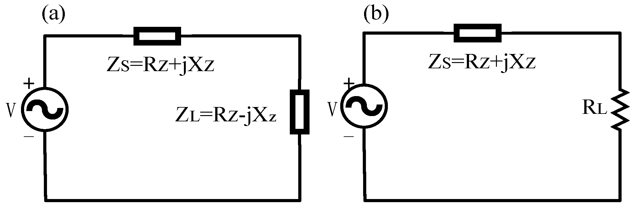
2.4. Impedance Characteristics of the Vibration-Threshold-Triggered Energy Harvester

When the impedance of the load is conjugated to the source impedance, the load extracts the maximum power from the source. Impedance matching is an effective way to increase the output power of a piezoelectric energy harvester. Using the equivalent circuit model of the vibration-threshold-triggered energy harvester, we can obtain the impedance characteristics of the piezoelectric energy harvester, which allows us to predict the output power of the energy harvester under different load conditions, allowing us to optimize the interface circuit.
The equivalent circuit model shown in Figure 4 can be simplified using Thevenin’s theorem, and the internal impedance of the energy harvester can be equivalent to the circuit shown in Figure 6, where
C S 1 = n 2 K 1 ;     C S 2 = C p ; R S = D 1 n 2 ;      L S = M 1 n 2 .
Then, the expression for the impedance Z s can be derived as
Z S = ( L S C S 2 1 ω 2 C S 1 C S 2 ) j R S ω C S 2 R S + j ( ω L S 1 ω C S 1 1 ω C S 2 ) = R Z + j X Z .
It can be seen that when the other parameters of the energy harvester are determined, the impedance Z s is only related to the frequency w . Using the established model, we can calculate the parameters of the equivalent circuit model, as shown in Table 2. Substituting these parameters into Equations (15) and (16), we calculate the impedance characteristics of the piezoelectric energy harvester, as shown in Figure 7. The impedance of the piezoelectric energy harvester is close to purely resistive near the open-circuit resonant frequency. Because our purpose is to increase the output power of the energy harvester, we only need to consider the state where the energy harvester is triggered. As noted above, when the energy harvester is triggered, the generating stage is in resonance. Thus, the impedance of the energy harvester is fixed in this state, and, more importantly, the impedance is close to pure resistance. This makes it easy for us to design the interface circuit.
As shown in Figure 8a, when the load impedance is conjugate matched to the source impedance, the load can achieve maximum power:
P Z , max = V 2 4 R Z .
As shown in Figure 8b, when a pure resistor is used as the load, the power obtained by the load is
P R = | V Z S + R L | 2 R L = V 2 R L + R Z 2 + X Z 2 R L + 2 R Z .
According to Equation (18), an optimal matching resistance can be found such that the power it obtains is maximized. The expression of this is as follows:
R L , o p t = R Z 2 + X Z 2 ,
P R , o p t = V 2 2 R Z 2 + X Z 2 + 2 R Z .
It is found that when the imaginary part of the source impedance is close to zero, the power obtained by the load is closer to the maximum power. Therefore, we consider the use of resistance for impedance matching. Kong et al. showed that when using pure resistance for impedance matching between the short-circuit resonant frequency and the open-circuit resonant frequency, the energy-harvesting efficiency can reach approximately 75% [33]. The fixed impedance of the energy harvester also greatly simplifies the circuit design. By taking the parameters shown in Table 2 for Equation (19), we can calculate that the optimal matching resistance of the energy harvester is 28.7 kΩ.

3. Interface Circuit of the Vibration-Threshold-Triggered Energy Harvester

3.1. Standard Energy-Harvesting Interface Circuit

Figure 9a shows the standard energy-harvesting interface circuit, which is usually composed of a rectifier and a storage capacitor. The AC voltage output from the energy harvester is converted into DC voltage by the rectifier, which then charges the storage capacitor and stores the energy in the capacitor. In previous work, the standard interface circuit was used. Although this circuit is simple, it is inefficient and cannot maximize the energy harvested.

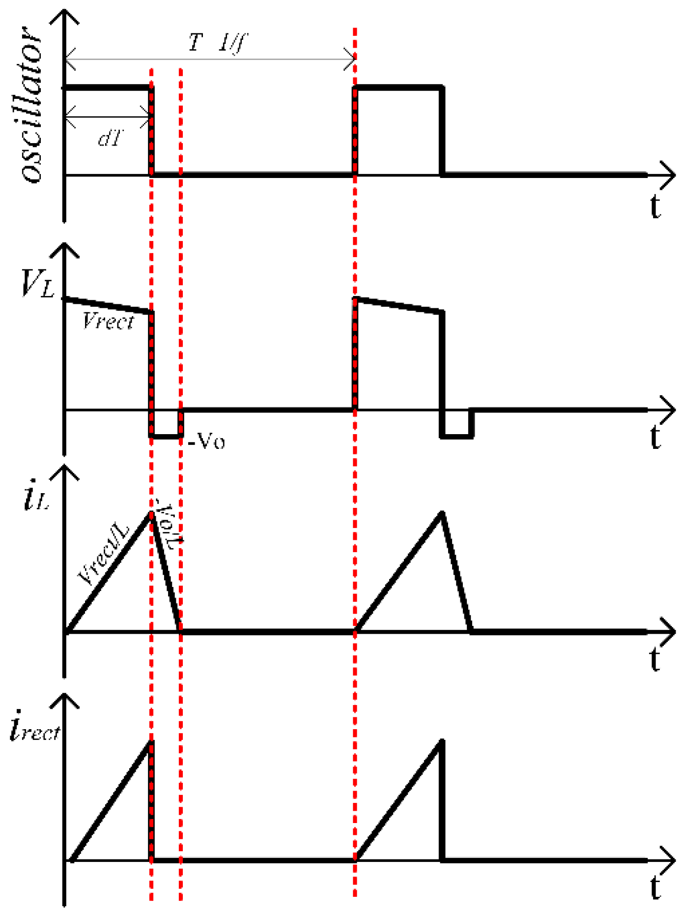
3.2. Improved Energy-Harvesting Interface Circuit

Figure 9b shows the improved energy-harvesting interface circuit proposed in this paper. A buck-boost converter operating in DCM (discontinuous current) mode is used to achieve the resistance matching of the piezoelectric energy harvester.
The working process of the buck-boost converter is shown in Figure 10.
(a) When the NMOS is on, the potential at the negative electrode of the diode is lowest, so the diode is reversed and the inductor begins to store energy.
(b) When the NMOS is off, the circuit I L begins to decrease, the induced voltage of the inductor turns the diode on, and the inductor begins to charge the capacitor. The working voltage and current waveform of the buck-boost converter are shown in Figure 11.
The input resistance of the buck-boost converter can be calculated by dividing V r e c t by the average current i r e c t . a v e r a g e of one cycle:
R i n = V r e c t i r e c t . a v e r a g e .
According to Figure 11, i r e c t . a v e r a g e can be calculated as
i r e c t . a v e r a g e = 1 T 0 d T V r e c t L t d t = V r e c t d 2 T 2 L .
Then, we obtain the following expression for input resistance:
R i n = 2 L V r e c t V r e c t d 2 T = 2 L f d 2 .
It should be noted that V r e c t is a constant value when the NMOS is turned on. To satisfy this assumption, the frequency of the oscillator needs to be much larger than the frequency of the output voltage of the energy harvester. It can be seen in Equation (23) that the input resistance is determined by the inductance L , oscillator frequency f , and its duty cycle d . This result is consistent with our design requirements. Because we calculate the optimal matching resistance of the piezoelectric energy harvester, we only need to select the appropriate circuit parameters so that R i n = R L , o p t , and then the resistance matching can be achieved. Furthermore, this relationship does not change as the load changes.

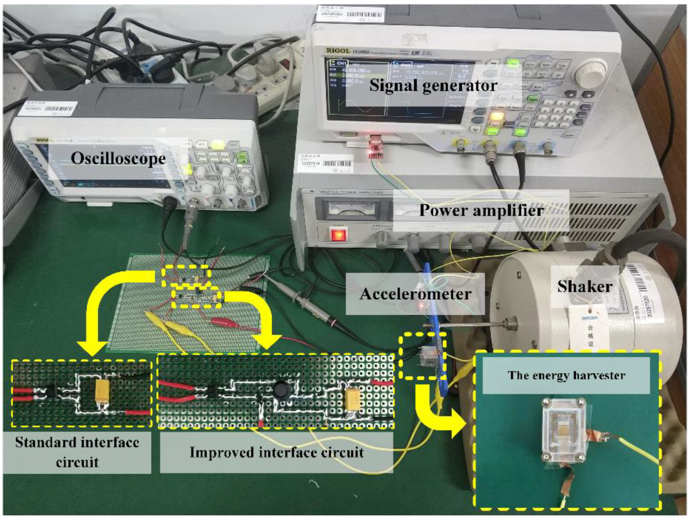
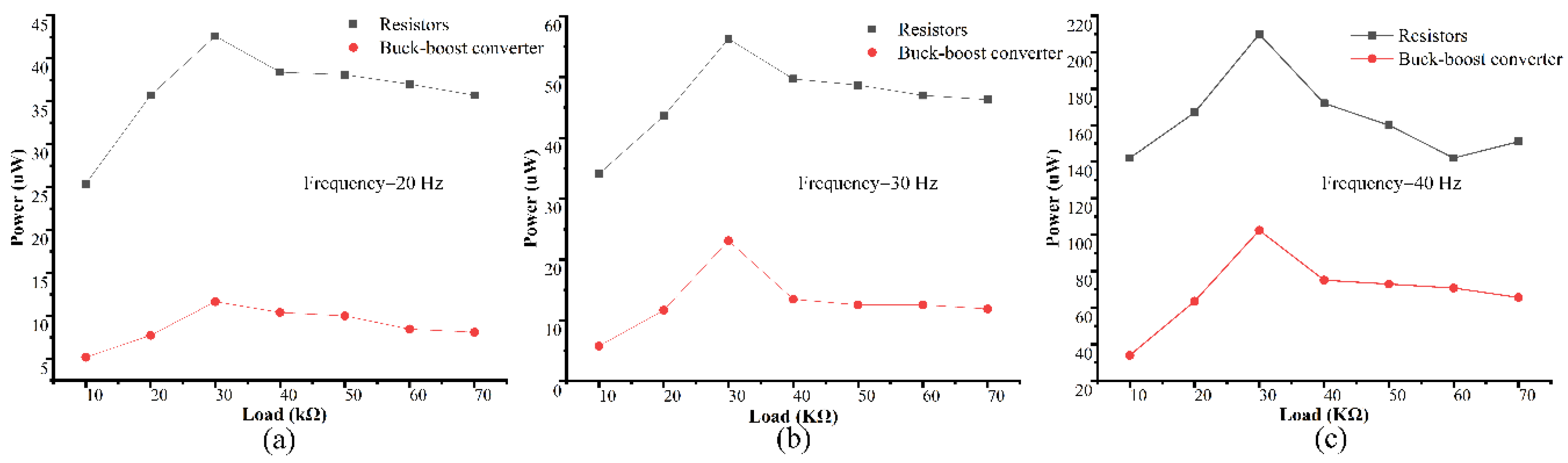
4. Experimental Results

To verify the feasibility of the proposed interface circuit, experiments were performed using standard energy-harvesting interface circuits and the interface circuits proposed in this paper. The experimental setup is shown in Figure 12. The vibration-threshold-triggered energy harvester was designed to operate in a low-frequency vibration environment of several tens of hertz, so the vibration frequency was set to 20, 30, and 40 Hz. Because we mainly focused on the power generated by the energy harvester, the vibration acceleration was set to 5.5 g, which ensured that the energy harvester would be triggered at all three frequencies.
First, to verify that the generating stage is in resonance when the energy harvester is operating, Figure 13 shows the output voltage of the energy harvester at three frequencies. The results show that when the vibration frequencies are 20 Hz, 30 Hz, and 40 Hz, the operating frequencies of the generating stage are about 303 Hz, 286 Hz, and 286 Hz, respectively. It can be found that the operating frequency of the generating stage is close to the calculated value of its resonance frequency (about 294 Hz).
Then, to verify the optimal matching resistance of the vibration-threshold-triggered energy harvester used, we tested the real output power of the energy harvester under different resistive loads. The result is shown in Figure 14. It can be seen that the output power is maximum when the load is 30 kΩ. Thus, the optimal matching resistance of the piezoelectric energy harvester is about 30 kΩ at three frequencies. According to Equation (16), the impedance of the energy harvester is only related to the vibration frequency of the piezoelectric material. Although the external excitation frequency was different, because the generating stage was in resonance, the impedance did not change. The optimal matching resistance obtained by the experiment is also consistent with the results of the calculation shown in Section 2.4.
Using the optimal impedance, we determined the device parameters for the proposed interface circuit. The frequency of the oscillator should be much larger than the output voltage frequency of the energy harvester. Because the resonant frequency of the generating stage is about 294 Hz, we chose the frequency of the oscillator to be at least 10 kHz, which is satisfactory. The appropriate level of inductance can be selected according to Equation (23). For larger inductors, the parasitic resistance would be larger, so there would be greater loss, and small inductors can cause large current ripples and require smaller duty cycles or higher frequencies, which are difficult to achieve. Therefore, a 47 mH inductor was selected here. Table 3 lists the components and parameters of the interface circuits shown in Figure 9.
The input resistance of the proposed interface circuit can be adjusted by changing the duty cycle and frequency of the oscillator. We tested the output power of the energy harvester under different levels of resistance, using the interface circuit as the load. Figure 14 compares the average power with the proposed interface circuit as the load and the average power with different resistors as the load. It can be seen from the experimental results that the load–power curve generated using the interface circuit as the load has the same tendency as the resistive load, which indicates that the proposed interface circuit behaves as a resistor. However, the output power when using the proposed interface circuit as the load was lower than the output power when using a purely resistive as the load. The reason is that the circuit components (such as inductors and diodes) consume part of the energy.
Finally, we adjusted the input impedance of the proposed interface circuit to 30 kΩ, which is the optimal matching resistance of the energy harvester that we used, and then we used the proposed interface circuit and standard energy-harvesting interface circuit to harvest energy. Using measurements of the voltage on the storage capacitor, the voltage waveforms of the storage capacitor using the standard energy-harvesting interface circuit and using the proposed interface circuit under the same conditions are plotted in Figure 15, which indicates that under the same conditions, the storage capacitor charges faster when using the interface circuit. Using two interface circuits, we calculated the average energy-harvesting power within 5 s. The results are shown in Table 4. It can be seen that compared to the standard interface circuit, in 5 s, the output power of the energy harvester is increased by 48.1–55.7% with the proposed interface circuit, which proves the effectiveness of the proposed circuit.

5. Discussion and Conclusions

To improve the interface circuit of the vibration-threshold-triggered piezoelectric energy harvester, we modeled and analyzed a vibration-threshold-triggered piezoelectric energy harvester, and established an equivalent circuit model. The impedance characteristics were calculated and experimentally verified. Because the generating stage is in resonance when the energy harvester is triggered, the energy harvester has a fixed impedance and is close to pure resistance. Thus, we found that resistance matching is an effective method for increasing the output power of the vibration-threshold-triggered piezoelectric energy harvester. Finally, an interface circuit based on a buck-boost converter was proposed. The energy-harvesting power of the proposed interface circuit and the standard energy-harvesting interface circuit were experimentally compared, and it was found that the proposed interface circuit could increase the energy-harvesting power by 48.1–55.7% over that achieved with the standard energy-harvesting interface circuit.
Future work will consider the design of a low-power consumption oscillator and realize the self-powering of the proposed interface circuit. Finally, we can apply the interface circuit to a wireless sensor node.

Author Contributions

Conceptualization, J.L. and D.X.; data curation, J.L., R.H., J.Y., and D.X.; formal analysis, R.H. and Q.H.; funding acquisition, D.X.; investigation, J.L.; methodology, J.L.; project administration, D.X. and X.L.; resources, D.X. and X.L.; software, J.L. and Q.H.; supervision, D.X. and X.L.; validation, J.L.; visualization, J.L.; writing—original draft, J.L.; writing—review and editing, J.L., J.Y., R.H., and D.X. All authors have read and agreed to the published version of the manuscript.

Funding

This research was funded by National Natural Science Foundation of China (NSFC), grant number 61834007.

Conflicts of Interest

The authors declare no conflict of interest.

References

  1. Xi, Y.; Guo, H.; Zi, Y.; Li, X.; Wang, J.; Deng, J.; Wang, Z.L. Multifunctional TENG for blue energy scavenging and self-powered wind-speed sensor. Adv. Energy Mater. 2017, 7, 1602397. [Google Scholar] [CrossRef]
  2. Lee, W.K.; Schubert, M.J.W.; Ooi, B.Y.; Ho, S.J.Q. Multi-source energy harvesting and storage for floating wireless sensor network nodes with long range communication capability. IEEE Trans. Ind. Appl. 2018, 54, 2606–2615. [Google Scholar] [CrossRef]
  3. Wang, H.; Jasim, A.; Chen, X. Energy harvesting technologies in roadway and bridge for different applications–A comprehensive review. Appl. Energy 2018, 212, 1083–1094. [Google Scholar] [CrossRef]
  4. Narita, F.; Fox, M. A review on piezoelectric, magnetostrictive, and magnetoelectric materials and device technologies for energy harvesting applications. Adv. Eng. Mater. 2018, 20, 1700743. [Google Scholar] [CrossRef] [Green Version]
  5. Suzuki, Y.; Miki, D.; Edamoto, M.; Honzumi, M. A MEMS electret generator with electrostatic levitation for vibration-driven energy-harvesting applications. J. Micromech. Microeng. 2010, 20, 104002. [Google Scholar] [CrossRef]
  6. Roundy, S.; Wright, P.K. A piezoelectric vibration based generator for wireless electronics. Smart Mater. Struct. 2004, 13, 1131–1142. [Google Scholar] [CrossRef] [Green Version]
  7. Wook, K.; Divij, B.; Shinkyu, J.; Dukhyun, C. Mechanical energy conversion systems for triboelectric nanogenerators: Kinematic and vibrational designs. Nano Energy 2019, 56, 307–321. [Google Scholar] [CrossRef]
  8. Ylli, K.; Hoffmann, D.; Willmann, A.; Becker, P.; Folkmer, B.; Manoli, Y. Energy harvesting from human motion: Exploiting swing and shock excitations. Smart Mater. Struct. 2015, 24, 025029. [Google Scholar] [CrossRef]
  9. Ju, S.; Ji, C.H. Impact-based piezoelectric vibration energy harvester. Appl. Energy 2018, 214, 139–151. [Google Scholar] [CrossRef]
  10. Guan, M.; Liao, W.H. Design and analysis of a piezoelectric energy harvester for rotational motion system. Energy Convers. Manag. 2016, 111, 239–244. [Google Scholar] [CrossRef]
  11. Kamel, T.M.; Elfrink, R.; Renaud, M.; Hohlfeld, D.; Goedbloed, M.; De Nooijer, C.; Jambunathan, M.; Van Schaijk, R. Modeling and characterization of MEMS-based piezoelectric harvesting devices. J. Micromech. Microeng. 2010, 20, 105023. [Google Scholar] [CrossRef]
  12. Tang, G.; Liu, J.; Yang, B.; Luo, J.-B.; Liu, H.; Li, Y.-G.; Yang, C.-S.; He, D.; Dao, D.V.; Tanaka, K.; et al. Fabrication and analysis of high-performance piezoelectric MEMS generators. J. Micromech. Microeng. 2012, 22, 065017. [Google Scholar] [CrossRef]
  13. Yang, Z.; Zhou, S.; Zu, J.; Inman, D. High-performance piezoelectric energy harvesters and their applications. Joule 2018, 2, 642–697. [Google Scholar] [CrossRef] [Green Version]
  14. Safaei, M.; Sodano, H.A.; Anton, S.R. A review of energy harvesting using piezoelectric materials: State-of-the-art a decade later (2008–2018). Smart Mater. Struct. 2019, 28, 113001. [Google Scholar] [CrossRef]
  15. Fan, K.; Tan, Q.; Zhang, Y.; Liu, S.; Cai, M.; Zhu, Y. A monostable piezoelectric energy harvester for broadband low-level excitations. Appl. Phys. Lett. 2018, 112, 123901. [Google Scholar] [CrossRef]
  16. Zhang, J.; Qin, L. A tunable frequency up-conversion wideband piezoelectric vibration energy harvester for low-frequency variable environment using a novel impact-and rope-driven hybrid mechanism. Appl. Energy 2019, 240, 26–34. [Google Scholar] [CrossRef]
  17. Tang, Q.; He, Q.; Li, M.; Dong, C.; Xu, D.; Li, X. Wireless alarm microsystem self-powered by vibration-threshold-triggered energy harvester. IEEE Trans. Ind. Electron. 2016, 63, 2447–2456. [Google Scholar] [CrossRef]
  18. He, Q.; Dong, C.; Li, K.; Wang, J.; Xu, D.; Li, X. A multiple energy-harvester combination for pattern-recognizable power-free wireless sensing to vibration event. Sens. Actuator A-Phys. 2018, 279, 229–239. [Google Scholar] [CrossRef]
  19. Badel, A.; Guyomar, D.; Lefeuvre, E.; Richard, C. Efficiency enhancement of a piezoelectric energy harvesting device in pulsed operation by synchronous charge inversion. J. Intell. Mater. Syst. Struct. 2005, 16, 889–901. [Google Scholar] [CrossRef]
  20. Lefeuvre, E.; Badel, A.; Richard, C.; Guyomar, D. Piezoelectric energy harvesting device optimization by synchronous electric charge extraction. J. Intell. Mater. Syst. Struct. 2005, 16, 865–876. [Google Scholar] [CrossRef]
  21. Du, S.; Amaratunga, G.A.J.; Seshia, A.A. A cold-startup SSHI rectifier for piezoelectric energy harvesters with increased open-circuit voltage. IEEE Trans. Power Electron. 2018, 34, 263–274. [Google Scholar] [CrossRef]
  22. Kwon, S.C.; Onoda, J.; Oh, H.U. Performance evaluation of a novel piezoelectric-based high-frequency surge-inducing synchronized switching strategy for micro-scale energy harvesting. Mech. Syst. Signal Proc. 2019, 117, 361–382. [Google Scholar] [CrossRef]
  23. Morel, A.; Gasnier, P.; Wanderoild, Y.; Pillonnet, G.; Badel, A. Short circuit synchronous electric charge extraction (SC-SECE) strategy for wideband vibration energy harvesting. In Proceedings of the IEEE International Symposium on Circuits and Systems (ISCAS), Florence, Italy, 27–30 May 2018. [Google Scholar] [CrossRef] [Green Version]
  24. Shi, G.; Xia, Y.; Wang, X.; Qian, L.; Ye, Y.; Li, Q. An efficient self-powered piezoelectric energy harvesting CMOS interface circuit based on synchronous charge extraction technique. IEEE Trans. Circuits Syst. I-Regul. Pap. 2018, 65, 804–817. [Google Scholar] [CrossRef]
  25. Chen, N.; Wei, T.; Jung, H.J.; Lee, S. Quick self-start and minimum power-loss management circuit for impact-type micro wind piezoelectric energy harvesters. Sens. Actuator A-Phys. 2017, 263, 23–29. [Google Scholar] [CrossRef]
  26. Chen, N.; Jung, H.J.; Jabbar, H.; Sung, T.H.; Wei, T. A piezoelectric impact-induced vibration cantilever energy harvester from speed bump with a low-power power management circuit. Sens. Actuator A-Phys. 2017, 254, 134–144. [Google Scholar] [CrossRef]
  27. Chen, N.; Wei, T.; Ha, D.S.; Jung, H.J.; Lee, S. Alternating resistive impedance matching for an impact-type microwind piezoelectric energy harvester. IEEE Trans. Ind. Electron. 2018, 65, 7374–7382. [Google Scholar] [CrossRef]
  28. Bao, M. Analysis and Design Principles of MEMS Devices; Elsevier: London, UK, 2005. [Google Scholar]
  29. Hobeck, J.D.; Inman, D.J. A distributed parameter electromechanical and statistical model for energy harvesting from turbulence-induced vibration. Smart Mater. Struct. 2014, 23, 115003. [Google Scholar] [CrossRef]
  30. Elvin, N.G.; Elvin, A.A. A general equivalent circuit model for piezoelectric generators. J. Intell. Mater. Syst. Struct. 2009, 20, 3–9. [Google Scholar] [CrossRef]
  31. Erturk, A.; Inman, D.J. A distributed parameter electromechanical model for cantilevered piezoelectric energy harvesters. Trans. ASME. J. Vib. Acoust. 2008, 130, 041002. [Google Scholar] [CrossRef]
  32. Akoun, G.; Yonnet, J.P. 3D analytical calculation of the forces exerted between two cuboidal magnets. IEEE Trans. Magn. 1984, 20, 1962–1964. [Google Scholar] [CrossRef]
  33. Kong, N.A.; Ha, D.S.; Erturk, A.; Inman, D.J. Resistive impedance matching circuit for piezoelectric energy harvesting. J. Intell. Mater. Syst. Struct. 2010, 21, 1293–1302. [Google Scholar] [CrossRef]
Figure 1. (a) Schematic view of the vibration-threshold-triggered piezoelectric energy harvester; (b) sectional view of the harvester; (c) working principles of the harvester.
Energies 13 03830 g001
Figure 2. Three phases during one stroke of generating operation.
Energies 13 03830 g002
Figure 3. Electromechanical of coupling spring-mass-damper model the harvester.
Energies 13 03830 g003
Figure 4. Equivalent circuit model of the harvester.
Energies 13 03830 g004
Figure 5. Sectional view of the generating stage.
Energies 13 03830 g005
Figure 6. Equivalent internal impedance of the energy harvester.
Energies 13 03830 g006
Figure 7. (a) Reactance and (b) resistance of the harvester obtained by the simplified equivalent circuit.
Energies 13 03830 g007
Figure 8. (a) Load impedance is conjugate matched to the source impedance; (b) Use of resistive load.
Energies 13 03830 g008
Figure 9. (a) Standard energy-harvesting interface circuit; (b) improved energy-harvesting interface circuit.
Energies 13 03830 g009
Figure 10. Working process of the buck-boost converter.
Energies 13 03830 g010
Figure 11. Working voltage and current waveform of the buck-boost converter.
Energies 13 03830 g011
Figure 12. Test setup for the proposed interface circuit.
Energies 13 03830 g012
Figure 13. The output voltage of the harvester at (a) 20 Hz, (b) 30 Hz, and (c) 40 Hz.
Energies 13 03830 g013
Figure 14. Power harvested using resistors and the buck-boost converter at (a) 20 Hz, (b) 30 Hz, (c) 40 Hz.
Energies 13 03830 g014
Figure 15. Comparison of the energy harvested by the standard and improved interface circuits. (a) 20 Hz; (b) 30 Hz; (c) 40 Hz.
Energies 13 03830 g015
Table 1. Parameters of the energy harvester.
ParameterSymbolValue
Thickness of sensing stagehs100 µm
Length of sensing stageLs13.0 mm
Mass of sensing stagem0.93 g
Width of sensing stagebs8.0 mm
Thickness of generating stagehg60 µm
Length of generating stageLg11.0 mm
Width of generating stagebg4.0 mm
Length of PZTLp5.5 mm
Thickness of PZThp60 µm
Young’s modulus of substrateYs110 Gp
Young’s modulus of PZTYp60 Gp
Density of substrateρs8800 kg/m3
Density of PZTρp7500 kg/m3
Damping constantsα04.894
α11.235 × 10⁻⁵
Piezoelectric couplingd31280 × 10−12 m/V
Relative electrical permittivityε4600
Gap distanceG750 µm
Residual magnetismBr1.0 T
Table 2. Model parameters of the energy harvester.
K 1   ( N / m ) M 1   ( kg ) D 1   ( N   S / m ) n C p   ( F )
298.9625.359 × 10−50.0037.030 × 10−41.679 × 10⁻⁸
Table 3. Components and parameters of the circuits shown in Figure 7.
ComponentsPart NumberNotes
Rectifier bridgeMB6SVFmax = 1.0 V
MOSFETSI2302VGS(th) = 1.2 V;
RDS(on) = 55 mΩ
Inductor L-47 mH
Diode DBAT54LVF = 0.4 V at 10 mA
Capacitor C1,C2AVX Tantalum capacitor100 μF
OscillatorGenerated by the signal generatorVM = 3 V; f = 15 kHz; d = 22%
Table 4. Comparison of average energy-harvesting power when using standard and improved interface circuits.
FrequencyAverage Energy-Harvesting Power (μW)Percentage Energy Increase (%)
Standard Interface CircuitImproved Interface Circuit
20 Hz7.110.852.1
30 Hz15.623.148.1
40 Hz62.5102.055.7

