Article

Cost-Effective Placement of Phasor Measurement Units to Defend against False Data Injection Attacks on Power Grid

School of Electronic and Electrical Engineering, Daegu Catholic University, 13-13 Hayang-ro, Hayang-eup, Gyeongsan-si, Gyeongbuk 38430, Korea
Energies 2020, 13(15), 3862; https://doi.org/10.3390/en13153862
Submission received: 13 July 2020 / Revised: 23 July 2020 / Accepted: 25 July 2020 / Published: 28 July 2020
(This article belongs to the Special Issue Micro Grid Protection)

Abstract

:
This study presents the phasor measurement unit (PMU) placement strategy in the presence of false data injection attacks which is one of the most serious security threats against power grid. It is focused on applications related to supervisory control and data acquisition (SCADA) systems where measurement data can be easily corrupted by adversaries without getting caught by the system. To safeguard power grids against malicious attacks, procedures have been proposed to facilitate the placement of secure PMUs to defend against false data injection attacks in a highly cost-effective way. It has formulated a method of identifying measurements that are vulnerable to false data injection attacks. It was discovered that a weak power grid can be transformed into a robust power grid by adding a few PMUs at vulnerable locations. Simulations on the IEEE standard test systems demonstrate the benefits of the proposed procedure.

1. Introduction

Cyber attacks are increasingly seen as a tremendous threat to modern power grid. As supervisory control and data acquisition (SCADA) systems become more interconnected, the connection between the power network and the Internet-connected management network makes them highly vulnerable to intrusions. The hackers may have already infiltrated the grid and left malicious code, causing serious security concerns. For example, in connection with the Northeast blackout of 2003, the first malicious software code known specifically to target SCADA systems were reported to have tried to infect thousands of remote terminal units (RTUs) [1]. On 23 December 2015, a synchronized and coordinated cyber attacks damaged three Ukrainian power distribution companies, causing power outages to approximately 225,000 customers over several hours [2]. This worm-like behavior exacerbates the problem if a compromised system can cause extensive damage to the power grid as well as other critical infrastructures.
The restructuring of the power industry has transformed state estimation from important applications to critical applications. It is a key feature of modern energy management systems (EMS), which must provide a complete, consistent and accurate database as input to all other online applications, including contingency analysis, optimal power flow and economic dispatch. The control center analyses information from different measurements and estimates the current system operating conditions. The conventional state estimator uses a set of measurements to estimate the bus voltage phasor on the power grid. To date, these measurements were obtained only through the SCADA systems, which collects real-time measurements from RTU installed at the substation [3].
One may add any type of measurement that will improve measurement redundancy and bad data detection; however, adding a phasor measurement unit (PMU) will potentially make the most impact. With the advent of global positioning system (GPS), the set of measurements can be extended to include time-synchronized phasor measurements provided by PMUs. A PMU installed on the bus can measure both the voltage phasor of the installed bus and the current phasors of some or all branches incident to the bus, assuming there is sufficient number of channels in the PMU. As the availability of PMUs at substations increases, the performance of various essential functions related to the monitoring, protection, and control of interconnected power grid is improved [4]. The topic of optimal PMU placement for full or redundant observability without considering cyber security was extensively studied based on the formulation of various optimization issues [5,6,7,8]. However, PMUs can also be used to improve cyber security capability in the sense that they cannot be easily subverted by the malicious attackers. PMUs are the most expensive and sophisticated device used in power systems which utilize the high accuracy computation [9]. In particular, the communication links between PMUs and control centers are usually secured and encrypted. PMUs are networked on the NASPInet architecture which has been designed for secure data transfer [10]. NASPInet was made to develop a secure, standardized, distributed and scalable data communications infrastructure to support synchro–phasor applications in North America. One such area is data communication where faster and more reliable communication channels have created the chance of streaming from RTU site to the control center.
This paper presents a simple, but effective procedure for optimal placement of PMUs that ensures full observability and high level of cyber security. The main goal is to improve security by taking advantage of the PMU. To achieve this, this paper proposes a framework that adds a few secure PMUs at buses with nonredundant measurements in the power grid to defeat false data injection attacks. It also formulates an optimization problem, the objective of which is to place a minimum number of secure PMUs at best locations meeting the requirements of both full observability and cyber security.
The remainder of this paper is organized as follows. The related works will be presented in Section 2. Power system modeling, state estimation and false data injection attacks are discussed in Section 3. In Section 4, identification of vulnerable locations is formulated. The proposed method for PMU placement is presented in Section 5. Simulations on each IEEE bus systems illustrating the effectiveness of the proposed method is discussed in Section 6.

2. Related Works

To date, the aim of PMU placement has been to minimize the number of PMU installations while ensuring the full observability of power grid [11]. Ahmadi et al. [12] proposed a binary particle swarm optimization that tries to minimize the number of PMUs needed for full observability, with or without the existence of conventional measurements. Emami et al. [13] proposed a branch PMU placement method for full observability taking into account PMU failures. Korkali et al. [14] formulated a mixed ILP algorithm for network observability considering a specified channel capacity for the candidate PMUs. The research studies mentioned above focused on finding the minimum number of PMUs for the full observability of a network in various situations. However, these studies did not consider cyber security issues. These methods may fail in the presence of intelligent cyber attacks.
Cyber attacks against SCADA systems can affect the state estimation results and lead to more misleading operations and control functions, which can have catastrophic consequences. The possible attacks shown in [15] can be denial-of-service (DoS) attacks on the RTUs, deception attacks on the data passed over the communication network or attacks directed to the SCADA master over a local area network (LAN). Some of the literature has already mentioned these problems such as false data injection attacks, security constrained control and replay attacks [16,17]. Human-made false data injection attacks against power grid state estimation was the first study by Liu et al. [17]. It was shown [17] that a malicious attacker can manipulate the state estimate while avoiding bad data detection. The attacker’s goal was either random or targeted false data injection attacks. Various practical false data injection attack detection algorithms have been designed as follows. Kosut et al. [18] assumed that they used a graph–theoretic approach to launch a stealthy false data injection attack. In [18], a computationally efficient algorithm was derived to detect false data injection attacks using the generalized likelihood ratio test. Huang et al. [19] proposed cumulative sum (CUSUM)-based quickest detection (QD) that represents a tradeoff between the attack detection speed and performance. Recently, Bobba et al. [20] and Kim et al. [21] investigated the use of a minimum set of meters to mitigate cyber attacks using heuristic algorithms. These approaches were used for a greedy algorithm. To achieve perfect protection in the method proposed in [20], it is necessary and sufficient for the operator to protect some meters that are chosen such that the submatrix of power network Jacobian matrix according to these meters has numerically full rank. Unfortunately, perfect protection is generally difficult in practice because the number of state variables in a power grid is typically large. In addition, Kim et al. [21] proposed a greedy algorithm that strategically identifies the measurements to be protected to increase the number of vulnerable meters for cyber attacks. The above strategy does not consider the impact of random or targeted attacks on given power grid. Furthermore, the proposed iterative greedy algorithm has heavy computational burden and it does not converge to global optimum. Hug et al. [22] proposed AC state estimation and presented techniques for performing a hidden false data injection vulnerability analysis. Mehdi et al. [23] proposed a novel bad data detection to identify false data injection attacks on the power system state estimation. This paper introduces and evaluates a novel false data injection attack detector by introducing nonlinear autoregressive exogenous (NARX) neural network and its prominent features to provide an attractive predictor engine to estimate of the states.

3. Preliminaries

This section introduces the power system model, theory of state estimation and basic principles of the false data injection attacks.

3.1. System Assumptions

In this study, it is assumed that:
  • Given power grids consist of active power flow measurements at all branches on both ends;
  • A simplified linearized approximation model is considered;
  • A PMU placed at a given bus can measure both the voltage and current phasor at all branches present at that bus;
  • The measurements obtained by the PMUs are secure since the PMU networked system has been designed for secure data transfer.

3.2. Active Power Flow Model

The given power grid has n buses. Only the model consisting of active power flows P i j and bus phase angles θ i (where i , j = 1 , , n ) is considered. Assuming that the resistance in the transmission line connecting buses i and j is small compared to its reactance, the active power flow model can be considered as follows [24]:
P i j = V i V j X i j s i n ( θ i θ j )
where V is a voltage magnitude and X is a reactance.

3.3. State Estimation

In this chapter, the state estimation problem is considered to estimate n phase angles given a set of active power flow measurements m . It assumes that the voltage level of each bus and the reactance of each transmission line are known.
For a given power grid, the linear approximation model for the active power flow measurements and bus phase angles can be expressed in the following form [17]:
z = H x + e
where z is active power flow measurements vector ( m × 1 ) ; H is constant Jacobian matrix ( m × n ) ; x is bus phase angle vector ( n × 1 ) ; and e is measurement error vector of independent zero-mean Gaussian variables with covariance matrix R , N ~ ( 0 , R ) , R = d i a g ( σ 1 2 , σ 2 2 , , σ m 2 ) where σ is the variance of meter error.
If the measurement error follows a standard normal distribution and m > n , which means the system is over-determined, the estimation problem can then be solved as follows.
x ^ = ( H T H ) 1 H T z
In general, bad data processor incorporated into state estimation is beneficial for power system application functions. However, bad data detection is closely related to the measurement redundancy, which means false data appearing in non-redundant measurements cannot be detected. This fact will be discussed in more detail in the Section 4.

3.4. False Data Injection Attacks: Basic Principle

The authors of [17] developed a method to construct an attack vector a . This theorem is that a = H c (where c is an arbitrarily injected error state vector) exists if and only if B a = 0 , where B = I H ( H T H ) 1 H T , B is a residual sensitivity matrix. Let P = H ( H T H ) 1 H T where P is a so-called projection matrix. If the attacker can compromise specific k meters, where k > m n , then there always exist attack vectors a = H c such that a 0 . In the control center, the measurement residual r (the difference between the observed values and the estimated values) is calculated as follows.
r = z z ^ = z H x ^ = ( I P ) z
If the residual r is larger than expected, an alarm is triggered, and invalid data are identified and eliminated. However, an attacker can access to information of H and launch a false data injection attack on the power grid to ensure that the corrupted state is not detected by the measurement residual test.

4. Identification of Vulnerable Locations to False data Injection Attacks

This section proposes a method to identify the vulnerable locations to false data injection attacks, especially sparse attacks with uncertain information. The model was designed assuming that the attacker has (1) perfect or (2) imperfect knowledge of the power grid. It then presents the evaluation metrics for construction of false data injection attacks.

4.1. Identification Method of Vulnerable Locations

Let’s denote the attacker’s understanding of the matrix H as
H = Y A
where Y is an ( m × m ) diagonal matrix of branch admittance information and A is an ( m × n ) connectivity binary information matrix. If an attacker has perfect information, the attack vector a can be configured in the following form.
a = Y A c B a = 0
However, if the attacker does not know the branch admittance information, then he or she can assume Y = I and obtain the attack vector a ( I is identity matrix).
a = A c B a = 0
where B is a residual sensitivity matrix of A , where B = I A ( A T A ) 1 A T . A set of most valid targeted attack vector a ˜ can be defined if there exist such attack vectors that a basis of nullspace (or kernel) of B and a basis of null space of B are the same.
Theorem 1.
The most valid targeted attack vector a ˜ always exists when an attacker knows the perfect power grid topology and the imperfect power grid topology.
a ¯ a ¯ = a ˜
a ¯ = K e r ( B ) { a I m ( H ) : B a = 0 } ,
a ¯ = K e r ( B ) { a I m ( A ) : B a = 0 }
where a ¯ and a ¯ are the basis set of nullspace of B and B , respectively. I m ( H ) and I m ( A ) are the image or range space, which is equivalent to have a = H c and a = A c , respectively, for some c 0 .
Proof of Theorem 1. 
Let Y m × m be a matrix describing a linear map between two spaces H m × n and A m × n , i.e., Y : A H . Then,
a = Y a
If the attacker does not know the structure of matrix Y , s/he will have difficulty finding attack vector a . However, s/he can easily construct the most valid targeted attack vector a ˜ since Y = d i a g { y 11 , y 11 , y 22 , y 22 , , y m m , y m m } , where y denotes admittance values, for some y 0 . Here the focus is on the most valid sparse targeted attacks that require the coordination of a small number of meters. In fact, false data injection attacks on a large numbers of meters are improbable because the attacker has limited resources. If all branches on both-ends are metered, there are standard forms that characterize all of the most valid 2-sparse targeted attacks. Therefore, the attack vector a ˜ can be obtained through the inverse matrix of Y .
a ˜ = Y 1 a = Y 1 H c = Y 1 Y A c = I A c = A c
An example 5-bus system is introduced to explain Theorem 1 in the next section.

Example 5-bus System

For example, in the power grid model shown in Figure 1, the following model is obtained in which the measured values consist of active power flows at all branches on both ends. It should be noted that the system observability is independent of the operating state of the system, as well as the branch parameters. If the attacker does not have perfect power grid topology information, then he or she can be assumed that matrix Y is the identity matrix [25].
A = [ 1 0 0 0 1 0 0 0 0 1 0 0 0 1 0 0 1 1 0 0 1 1 0 0 1 0 1 0 1 0 1 0 1 0 0 1 1 0 0 1 0 1 1 0 0 1 1 0 ]
where x = ( θ 2 , θ 3 , θ 4 , θ 5 ) T and θ 1 is a reference bus phase angle. The reference bus is normally excluded from the states and the corresponding column does not exist in matrix A . Here A T A is invertible, and it can estimate the phase angles in the power grid. Now, matrix B becomes
B = [ 0.6875 0.3125 0 0 0.0625 0.3125 0.6875 0 0 0.0625 0.1875 0.1875 0 0 0.0625 0 0 0.5 0.5 0 0 0 0.5 0.5 0 0.0625 0.0625 0 0 0.6875 ]
Matrix B represents the most vulnerable measurements, i.e., column 9 and 10 that means meter measurements in branches 2–5, are sensitive to valid targeted attack. Ideally, the attacker would like to use as few meters as possible to reduce the cost of an attack. As discussed in [17], the attack vector a contains corrupted values to be added to the real measurement z . The attacker’s goal is to fool the EMS into thinking that a particular power flow measurement is z a = z + a . The attacker needs to find a most valid targeted attack vector a ˜ such that B a ˜ = 0 . For example, the attacker represents a ˜ as a ˜ = ( 0 , 0 , 0 , 0 , 0 , 0 , 0 , 0 , 1 , 1 , 0 , 0 ) T . Let B = ( b 1 , b 2 , , b 12 ) , where b l ( 1 l 12 ) is the l -column vector of B . Then,
B a ˜ = 0 ( b 1 , b 2 , , b 12 ) · ( 0 , 0 , , 1 , 1 , 0 , 0 ) T = 0
It uses branch reactance to indicate the real power grid topology to evaluate whether such attacks are successful.
H = [ 16.66 0 0 0 16.66 0 0 0 0 4.16 0 0 0 4.16 0 0 5.55 5.55 0 0 5.55 5.55 0 0 8.33 0 5.55 0 8.33 0 5.55 0 1 0 0 8.33 1 0 0 8.33 0 33.33 33.33 0 0 33.33 33.33 0 ]
Now, the matrix B becomes:
B = [ 0.5231 0.4769 0 0 0.0057 0.4769 0.5231 0 0 0.0057 0.0927 0.0927 0 0 0.0228 0 0 0.5 0.5 0 0 0 0.5 0.5 0 0.0057 0.0057 0 0 0.5082 ]
Likewise, the attacker can represent a ˜ as a ˜ = ( 0 , 0 , 0 , 0 , 0 , 0 , 0 , 0 , 1 , 1 , 0 , 0 ) T . Let B = ( b 1 , b 2 , , b 12 ) , where b l ( 1 l 12 ) is the l th column vector of B . Then,
B a ˜ = 0 ( b 1 , b 2 , , b 12 ) · ( 0 , 0 , , 1 , 1 , 0 , 0 ) T = 0
The nonzero l th element means that the attacker compromises the l th meter, and then replaces the original measurement with a corrupted one. By launching such a targeted attack, the attacker can manipulate the injected false data to bypass the bad data detection and cause arbitrary errors in the state estimation results.

4.2. Impacts of Adding a PMU on Power Grid

Like an earlier example, assuming the voltage magnitudes | V i | = 1 , reactances X i j = 1 and no shunt lines for the power grid in Figure 1, the PMU is installed on bus 5 to obtain the following augmented model:
A a u g = [ A A p m u ] = [ 1 0 0 0 1 0 0 0 0 1 0 0 0 1 0 0 1 1 0 0 1 1 0 0 1 0 1 0 1 0 1 0 1 0 0 1 1 0 0 1 0 1 1 0 0 1 1 0 0 0 0 1 1 0 0 1 ]
where A a u g is augmented Jacobian and A p m u is rows correspond to the phasor measurements. The augmented measurements are the phase angle in bus 5 and the current flowing from branch 5 to 2. Then the matrix B a u g of the augmented model becomes:
B a u g = [ 1.7468 0.0633 0.0633 0.0633 0.2532 0.0633 0.0633 0.0633 0.0633 1.7342 0.2658 0.2658 0.0633 0.2658 1.7342 0.2658 0.0506 0.0127 0.0127 0.0127 0.1899 0.2025 0.2025 0.2025 0.0633 0.2658 0.2658 1.7342 ]
In the example above, the attacker cannot always generate valid attack vectors to inject the arbitrary errors into the state variable estimate in the case of a false data injection attack.
B a u g a ˜ 0
Therefore, the possibility of generating valid targeted attack vectors is primarily of interest and shows how likely the attacker can find such attack vectors to attack power grid with or without PMUs.
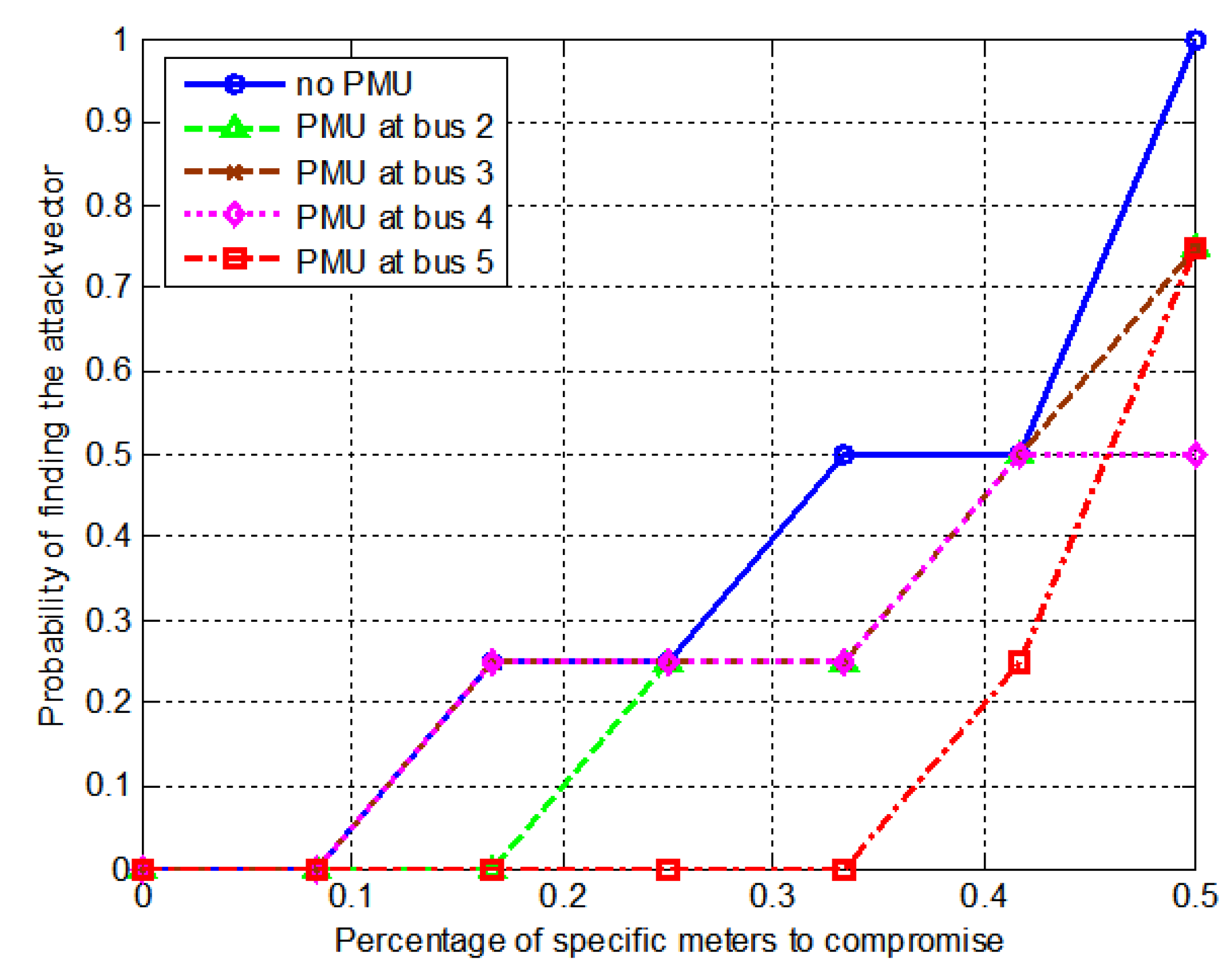
Based on the evaluation objective, it uses the following evaluation metrics: the probability that the attacker can successfully construct an attack vector given the specific meters. Figure 2 shows the relationship between the success probability and the percentage of specific meters to compromise in the example 5-bus system with/without PMU. In the “no PMU” case, an attacker would need to compromise about 10% or more of the meters to get the probability to construct an attack vector. In the “PMU at bus 5 (bus 5 is a vulnerable bus with 1 conventional meter)”, an attacker needs to compromise about 35% or more of the meters. When an attacker targets a vulnerable location, s/he only needs to compromise a few meters (about less than 10%). Thus, the power grid is secured against the targeted attacks when the PMU is installed at bus 5 rather than the other buses.

5. Proposed PMU Placement Algorithm Considering Cyber Security Constraint

This section presents an optimization problem whose objective is to place a minimal number of PMUs at best locations so that all nonredundant measurements are transformed into redundant ones. An integer linear programming (ILP)-based algorithm for the PMU placement has been modified to determine optimal PMU locations to ensure full observability under cyber security constraint. The proposed ILP-based optimization problems are:
min i n w i
s u b j e c t   t o   A O X 1 ^
A S X 1 ^
X = [ w 1 , w 2 , , w n ] T ,   w i { 0 , 1 }
where
  • n : total number of buses;
  • 1 ^ : vector whose entries are all equal to 1;
  • A O : binary information matrix of connectivity between all buses with/without conventional meters;
  • A S : binary information matrix of connectivity between vulnerable buses identified by the matrix B ;
  • X : binary (0/1) vector.
Equation (20) expressed the full observability and cyber security constraints, respectively. Thus, the solution X of the proposed optimization problem will provide the robust placement of PMUs which will eliminate all vulnerable locations for targeted attacks.
In order to take cyber security into account, while placing the PMUs in the power grid for full observability, the power grid can be considered as a graph comprising of G ( V , ) where V and represent buses and branches, respectively. The vulnerable branches can be seen as events resulting in a graph with vulnerable buses. Based on the above concept, a procedure for incorporating cyber security into a topological observability based PMU placement algorithm is developed. The proposed procedure can be explained with the help of the ILP-based PMU placement algorithm. The benefits of this new configuration are that the system will no longer be vulnerable to targeted attacks and the number of PMUs can be reduced.
The proposed ILP-based PMU placement algorithm is summarized as follows:
(1)
Identify rows of min P l 0 in the matrix P ;
(2)
Identify a l if and only if b a l = 0 ;
(3)
Find the full observability constraint;
(4)
Find the cyber security constraint; the cyber security constraint in the proposed ILP algorithm is modified by determined vulnerable locations;
(5)
The total solution is obtained by the proposed ILP algorithm.

6. Simulation Results

To validate the proposed procedure introduced above, we have performed simulations on IEEE 14-bus, 30-bus and 118-bus systems. Configuration data of the test systems obtained from the MATPOWER package was used [26]. In each test system, the state variables were the phase angles of its own buses, and measurements were active power flows at all branches on both ends, given the conventional meters.

6.1. IEEE 14-Bus System

The placement of secure PMUs by the proposed method was considered. Figure 3 shows the IEEE 14-bus system. The IEEE 14-bus system consists of 14 buses, 20 branches and 5 generators with reference bus B1.
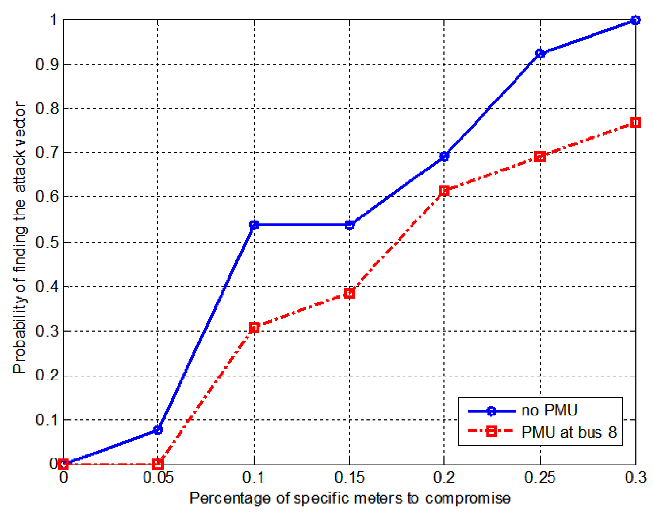
Thus, 4 PMUs are required for full observability under cyber security achievement without conventional meters. In the case of full observability under cyber security with conventional meters, 1 required PMU could be obtained. Checking the redundancy of matrix B in this system, it could obtain vulnerable locations B7 and B8 in branch 7–8. The placement of a secure PMU at bus 8 made the power grid completely secure from false data injection attacks because the matrix B has a full degree of redundancy, i.e., all B l 0 = 40 . For evaluation, the metrics of probability of finding attack vectors are shown in Figure 4.
The final proposed ILP solution for full observability under cyber security is B8. The results are summarized in Table 1.

6.2. IEEE 30-Bus System

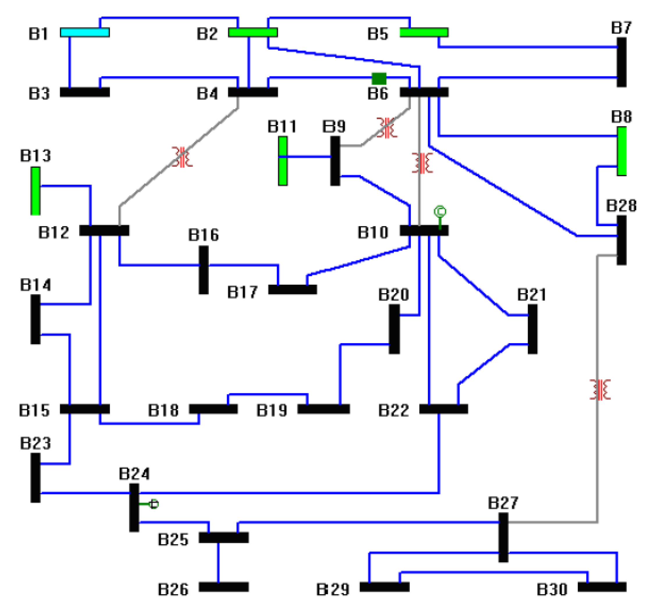
Figure 5 shows the IEEE 30-bus system. The IEEE 30-bus system consists of 30 buses, 41 branches and 6 generators with reference bus B1.
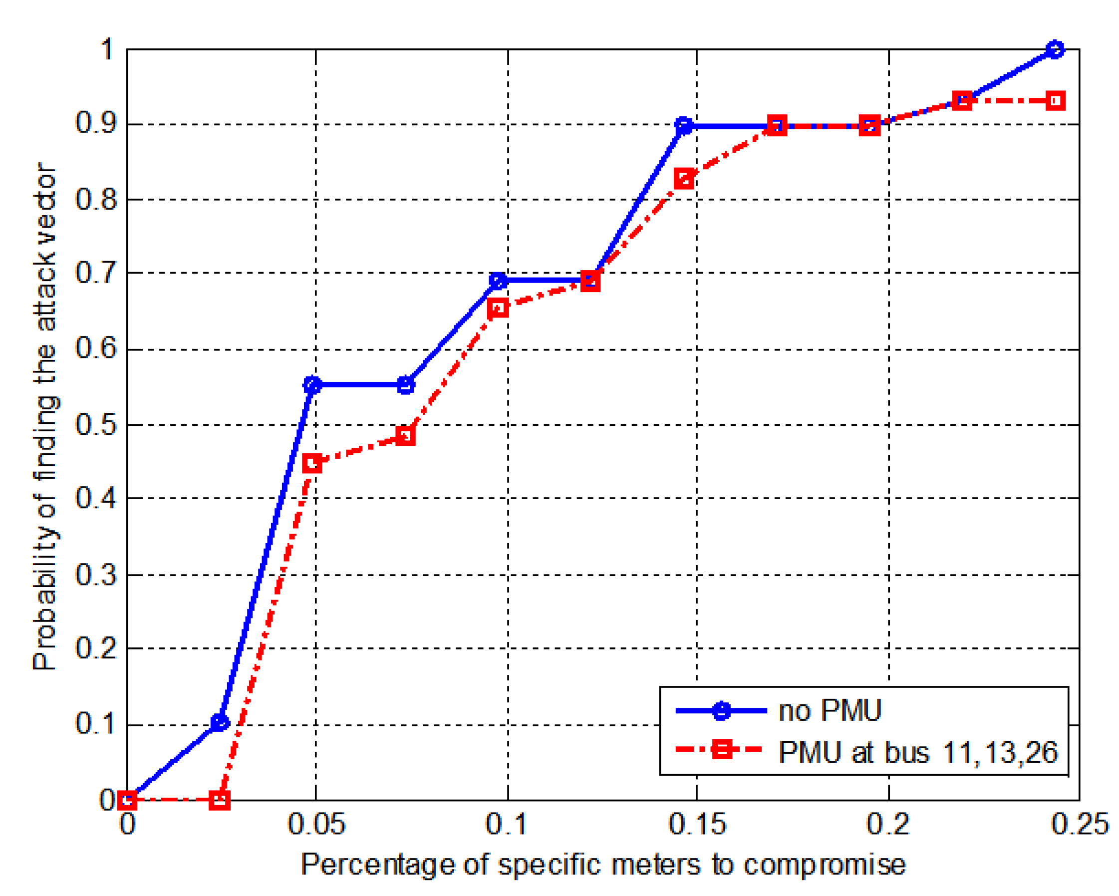
Thus, 10 PMUs are required for full observability considering cyber security achievement without conventional meters. In the case of full observability considering cyber security with conventional meters, 3 required PMUs could be obtained. Checking the redundancy of matrix B in this system, it could obtain vulnerable locations, B9, B11, B12, B13, B25 and B26. The secure PMU candidate placement sets are (B9, B12, B25), (B9, B12, B26), (B11, B13, B26), (B9, B13, B25), (B9, B13, B26), (B11, B12, B25), (B11, B12, B26) and (B11, B13, B25). The placement of PMU at buses (B11, B13, B26) made the power grid completely secure from false data injection attacks because matrix B has a full degree of redundancy, i.e., all B l 0 = 82 . For evaluation, the metrics of the probability of finding attack vectors are shown in Figure 6.
The proposed ILP solution results are summarized in Table 2.

6.3. IEEE 118-Bus System

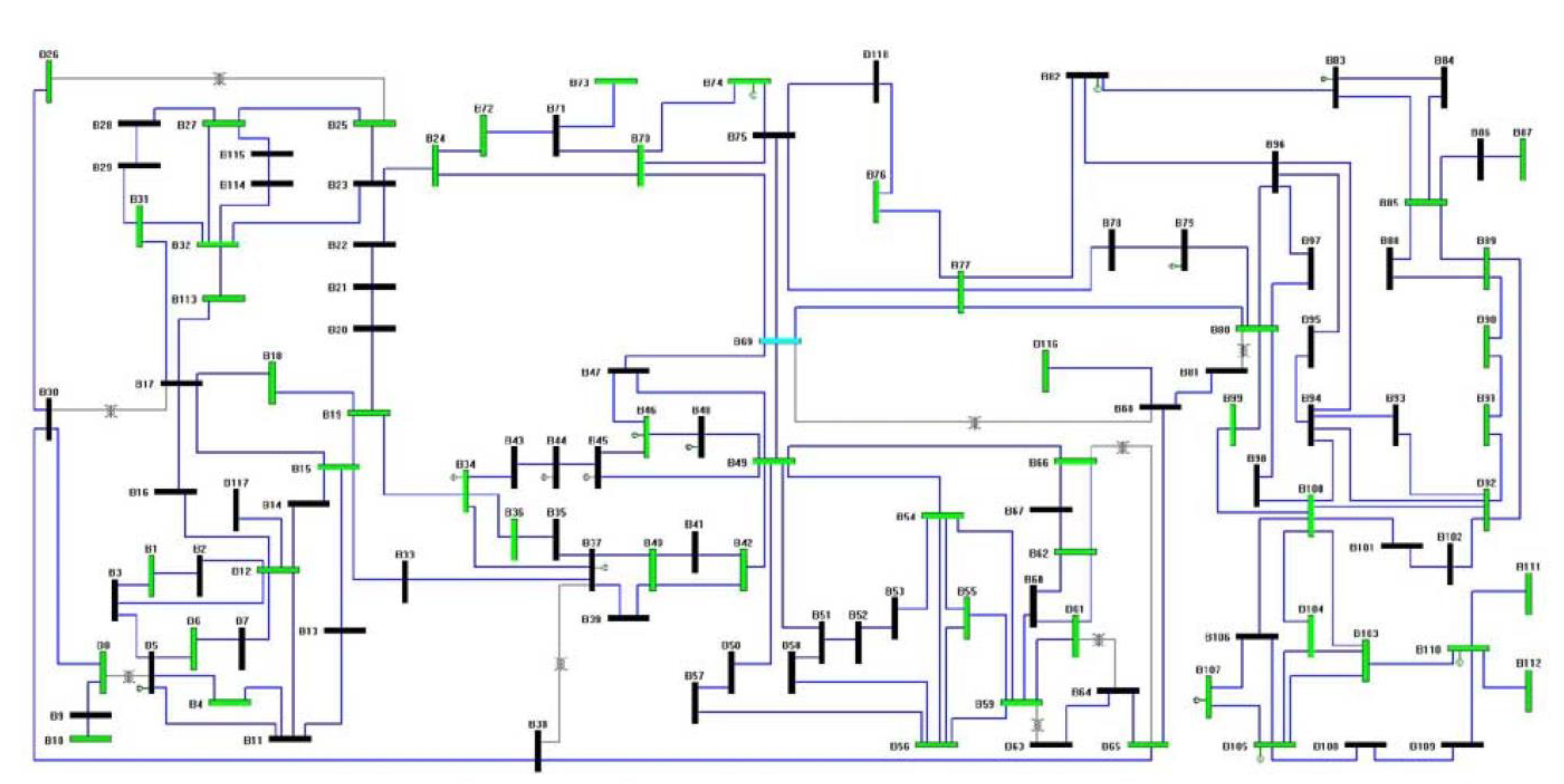
Figure 7 shows the IEEE 118-bus system. The IEEE 118-bus system consists of 118 buses, 186 branches and 54 generators with reference bus B1.
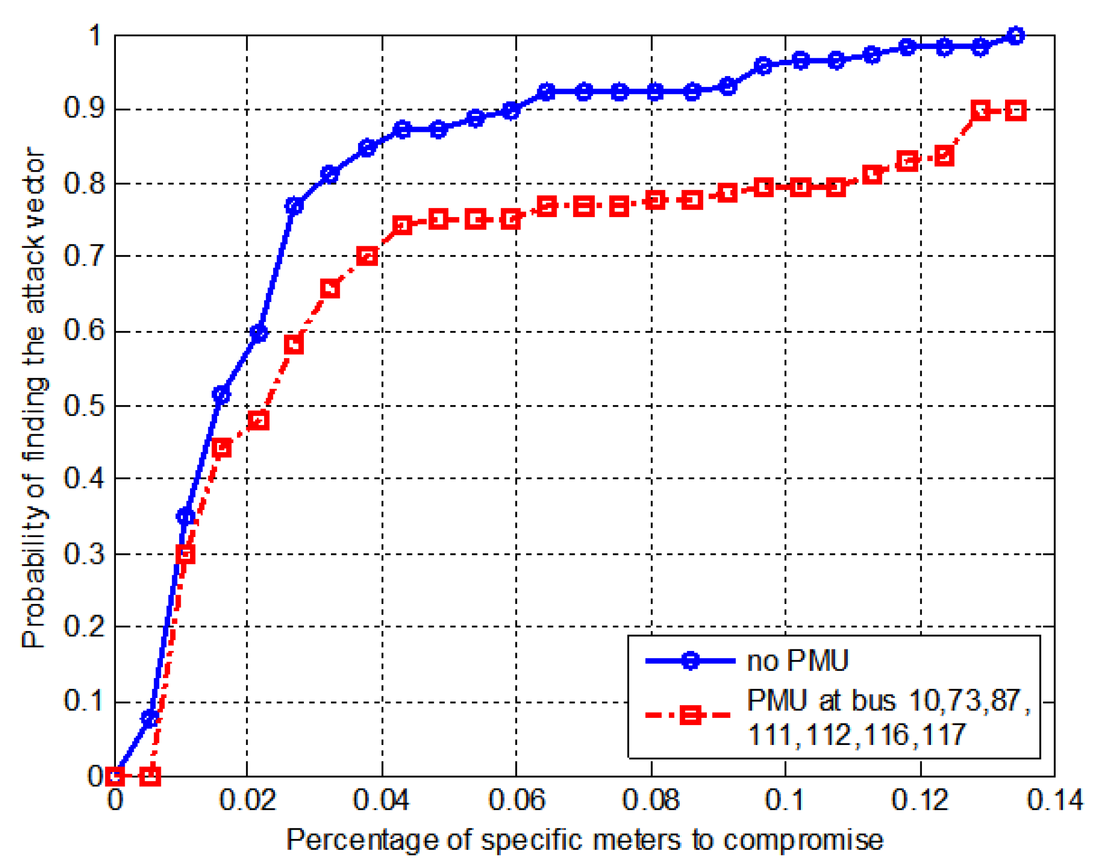
As a result, 32 PMUs are required for full observability considering cyber security achievement without conventional meters. In the case of full observability considering cyber security with conventional meters, 7 required PMUs could be obtained. Checking the redundancy of matrix B in this system, it could obtain the following vulnerable locations, B8, B9, B10, B12, B68, B71, B73, B85, B86, B87, B110, B111, B112, B116 and B117. The placement of PMUs at buses (B10, B73, B87, B111, B112, B116, B117) makes the power grid completely secure from false data injection attacks because matrix B has a full degree of redundancy, i.e., all B l 0 = 372 . For evaluation, the metrics of probability of finding attack vectors are shown in Figure 8.
The proposed ILP solution results are summarized in Table 3.

7. Conclusions

In this paper, the problem of sparse targeted false data injection attacks on meters of power grid was introduced and it shown that these cyber attacks could lead to incorrect the state estimation results. The attacker can take advantage of the configuration of a power grid to launch targeted attacks that bypass the existing bad data detection methods. To defend against these attacks, procedure was proposed to identify vulnerable locations from the projection and residual sensitivity matrix and the ILP algorithm was used to formulate the problem of secure PMU placement under both full observability and cyber security constraints. The proposed method can be used in the design of any power grid topology for cyber security under various conditions. Finally, we demonstrated on the IEEE bus systems that our method is more secure and economical for defense against sparse targeted false data injection attacks. These results can be helpful in building power grid that are less vulnerable to false data injection attacks. In summary, the main contributions of this study are the following:
(1)
Identification of vulnerable locations when an attacker has perfect or imperfect knowledge about the topology of power grid;
(2)
Suggestion of evaluation metrics to prove vulnerable locations;
(3)
Development of an integer linear programming-based algorithm considering both full observability and cyber security constraints.
The proposed method is expected to contribute to defending the power grid against the false data injection attacks as a low-cost and highly efficient protection strategy.
Future research topics include the cyber security of state estimation using AC power flow model and anomaly detection techniques to defend against false data injection attacks in power grid, such as a data-driven approach. In addition, these studies for cyber attacks and defenses can be extended to wide area measurement systems (WAMS) or micro grid linked to distributed generations and storage such as photovoltaic panels and plug-in electric vehicles.

Funding

This research received no external funding.

Acknowledgments

This work was supported by research grants from Daegu Catholic University in 2020. (No. 20203003).

Conflicts of Interest

The author declares no conflict of interests.

References

  1. Teixeira, A.; Amin, S.; Sandberg, H.; Johansson, K.H.; Sastry, S.S. Cyber-security analysis of state estimators in electric power systems. In Proceedings of the IEEE Conference on Decision and Control (CDC), Atlanta, GA, USA, 15–17 December 2010; pp. 5991–5998. [Google Scholar]
  2. Liang, G.; Weller, S.R.; Zhao, J.; Luo, F.; Dong, Z.Y. The 2015 Ukraine Blackout: Implications for False Data Injection Attacks. IEEE Trans. Power Syst. 2017, 32, 3317–3318. [Google Scholar] [CrossRef]
  3. Manousakis, N.M.; Korres, G.N.; Georgilakis, P.S. Taxonomy of PMU placement methodologies. IEEE Trans. Power Syst. 2012, 27, 1070–1077. [Google Scholar] [CrossRef]
  4. Chen, J.; Abur, A. Placement of PMUs to enable bad data detection in state estimation. IEEE Trans. Power Syst. 2006, 21, 1608–1615. [Google Scholar] [CrossRef]
  5. Ree, J.; Centeno, V.; Thorp, J.S.; Phadke, A.G. Synchronized phasor measurement applications in power systems. IEEE Trans. Smart Grid 2010, 1, 20–27. [Google Scholar]
  6. Gou, B. Generalized integer linear programming formulation for optimal PMU placement. IEEE Trans. Power Syst. 2008, 23, 1099–1104. [Google Scholar] [CrossRef]
  7. Chakra barti, S.; Kyriakides, E.; Eliades, D.G. Placement of synchronized measurements for power system observability. IEEE Trans. Power Del. 2009, 24, 12–19. [Google Scholar] [CrossRef] [Green Version]
  8. Abbasy, N.H.; Ismail, H.M. A unified approach for the optimal PMU location for power system state estimation. IEEE Trans. Power Syst. 2009, 24, 806–813. [Google Scholar] [CrossRef]
  9. Aminifar, F.; Khodaei, A.; Fotuhi-Firuzabad, M.; Shahidehpour, M. Contingency-constrained PMU placement in power networks. IEEE Trans. Power Syst. 2010, 25, 516–523. [Google Scholar] [CrossRef]
  10. Wells, C.; Moore, A.; Tjader, K.; Isaacs, W. Cyber secure synchrophasor platform. In Proceedings of the IEEE PES Power Systems Conference & Exposition, Phoenix, AZ, USA, 20–23 March 2011; pp. 1–4. [Google Scholar]
  11. Phadke, A.G.; Thorp, J.S.; Nuqui, R.F.; Zhou, M. Recent developments state estimation with phasor measurements. In Proceedings of the IEEE PES Power Systems Conference & Exposition, Seattle, DC, USA, 15–18 March 2009; pp. 1–7. [Google Scholar]
  12. Ahmadi, A.; Alinejad-Beromi, Y.; Moradi, M. Optimal PMU placement for power system observability using binary particle swarm optimization and considering measurement redundancy. Expert Syst. Appl. 2011, 38, 7263–7269. [Google Scholar] [CrossRef]
  13. Emami, R.; Abur, A. Robust measurement design by placing synchronized phasor measurements on network branches. IEEE Trans. Power Syst. 2010, 25, 38–43. [Google Scholar] [CrossRef]
  14. Korkali, M.; Abur, A. Impact of network sparsity on strategic placement of phasor measurement units with fixed channel capacity. In Proceedings of the IEEE International Symposium on Circuits and Systems, Paris, France, 30 May–2 June 2010; pp. 3445–3448. [Google Scholar]
  15. Giani, A.; Sastry, S.S.; Johansson, K.H.; Sandberg, H. The VIKING Project: An initiative on resilient control of power networks. In Proceedings of the 2nd International Symposium on Resilient Control Systems, Idaho Falls, Idaho, 11–13 August 2009. [Google Scholar]
  16. Mo, Y.; Sinopoli, B. Secure control against replay attack. In Proceedings of the 47th Annual Allerton Conference on Communication, Control, and Computing (Allerton), Monticello, IL, USA, 30 September–2 October 2009. [Google Scholar]
  17. Liu, Y.; Ning, P.; Reiter, M.K. False data injection attacks against state estimation in electric power grids. In Proceedings of the 16th of ACM Conference on Computer and Communications Security, Chicago, IL, USA, 30 September–2 October 2009. [Google Scholar]
  18. Kosut, O.; Jia, L.; Thomas, R.; Tong, L. Malicious data attacks on smart grid state estimation: Attack strategies and countermeasures. In Proceedings of the IEEE Conference on Smart Grid Communications, Gathersburg, MD, USA, 4–6 October 2010. [Google Scholar]
  19. Huang, Y.; Li, H.; Campbell, K.A.; Han, Z. Defending false data injection attack on smart grid network using adaptive cusum test. In Proceedings of the IEEE Conference on Information Sciences and Systems, Baltimore, MD, USA, 23–25 March 2011. [Google Scholar]
  20. Bobba, R.; Rogers, K.; Wang, Q.; Khurana, H.; Nahrstedt, K.; Overbye, T. Detecting False Data Injection Attacks on DC State Estimation. In Proceedings of the 1st Workshop on Secure Control Systems (SCS 2010), Stockholm, Switzerland, 12 April 2010. [Google Scholar]
  21. Kim, T.T.; Poor, H.V. Strategy protection against data injection attacks on power grids. IEEE Trans. Smart Grid. 2011, 3, 326–333. [Google Scholar] [CrossRef]
  22. Hug, G.; Giampapa, J.A. Vulnerability assessment of AC state estimation with respect to false data injection cyber-attacks. IEEE Trans. Smart Grid. 2012, 3, 1362–1370. [Google Scholar] [CrossRef] [Green Version]
  23. Ganjkhani, M.; Fallah, S.N.; Badakhshan, S.; Shamshirband, S.; Chau, K. A novel detection algorithm to identify false data injection attacks on power system state estimation. Energies 2019, 12, 2209. [Google Scholar] [CrossRef] [Green Version]
  24. Abur, A.; Exposito, A.G. Power System State Estimation: Theory and Implementation; CRC Press: Boca Raton, FL, USA, 2004. [Google Scholar]
  25. Bae, J.; Lee, S.; Kim, Y.W.; Kim, J.H. Protection strategies against false data injection attacks with uncertain information on electric power grids. J. Electr. Eng. Technol. 2017, 12, 19–28. [Google Scholar] [CrossRef] [Green Version]
  26. MATPOWER, A MATLAB Power System Simulation Package [Online]. Available online: http://www.pserc.cornell.edu/matpower/ (accessed on 20 June 2019).
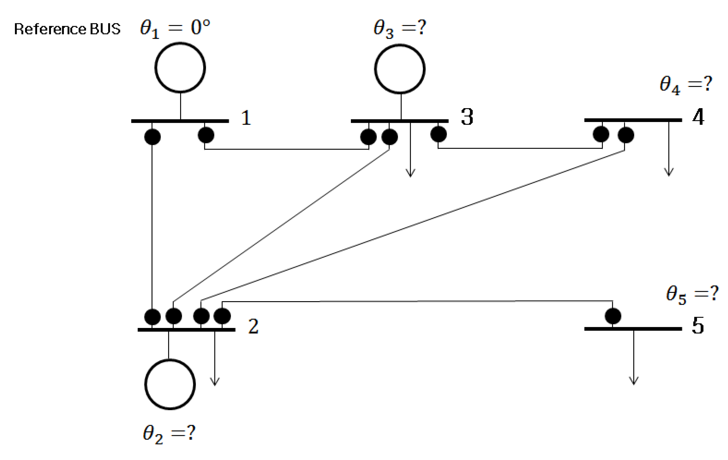
Figure 1. Example 5-bus system.
Energies 13 03862 g001
Figure 2. Probability of finding the attack vector in example 5-bus system with or without phasor-measurement unit (PMU).
Energies 13 03862 g002
Figure 3. IEEE 14-bus system.
Energies 13 03862 g003
Figure 4. Probability of finding the attack vector in IEEE 14-bus system.
Energies 13 03862 g004
Figure 5. IEEE 30-bus system.
Energies 13 03862 g005
Figure 6. Probability of finding the attack vector in IEEE 30-bus system.
Energies 13 03862 g006
Figure 7. IEEE 118-bus system.
Energies 13 03862 g007
Figure 8. Probability of finding the attack vector in IEEE 118-bus system.
Energies 13 03862 g008
Table 1. PMU placement to ensure cyber security with/without conventional meters in IEEE 14-bus system.
Given TopologyNumber of Required PMUPMU Placement
Without Meters4B2, B6, B7, B9
With Meters1B8
Table 2. PMU placement to ensure cyber security with/without conventional meters in IEEE 30-bus system.
Given TopologyNumber of Required PMUPMU Placement
Without meters10B1, B7, B9, B10, B12, B18, B24, B25, B27, B28
With meters3B11, B13, B26
Table 3. PMU placement to ensure cyber security with/without conventional meters in IEEE 118-bus system.
Given TopologyNumber of Required PMUPMU Placement
Without meters32B2, B5, B9, B11, B12, B17, B21, B24, B25, B28, B34, B37, B40, B45, B49, B52, B56, B62, B63, B68, B73, B75, B77, B80, B85, B86, B90, B94, B101, B105, B110, B114
With meters7B10, B73, B87, B111, B112, B116, B117