Efficient FEC Scheme for Solar-Powered WSNs Considering Energy and Link-Quality


Abstract
:1. Introduction
2. Related Work
2.1. WSN Technologies
2.2. SP-WSNs
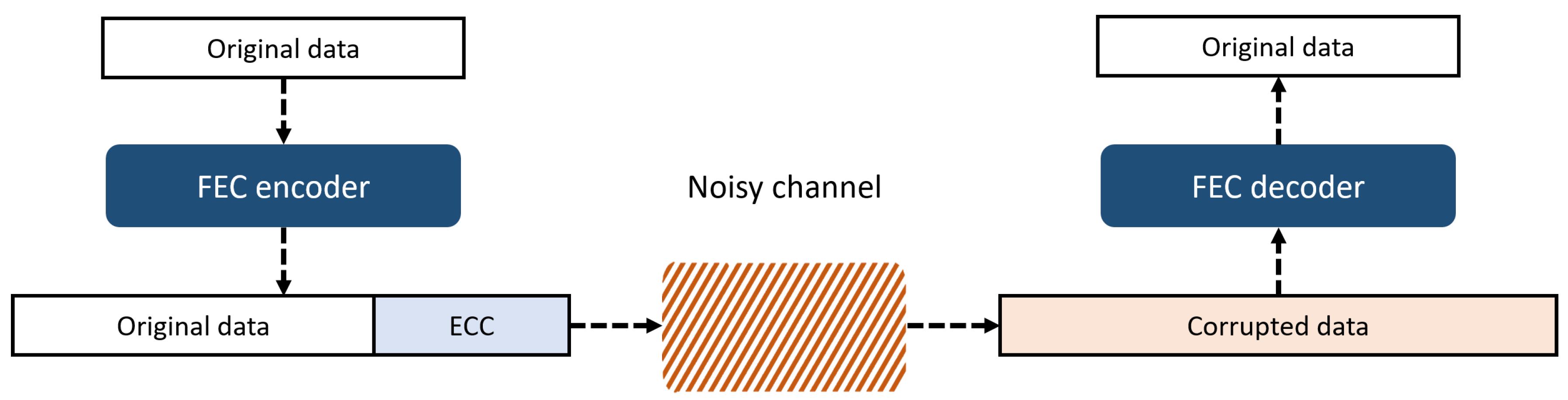
2.3. FEC Schemes
2.4. Reed–Solomon (RS) Scheme
3. Enhanced FEC Scheme for SP-WSN
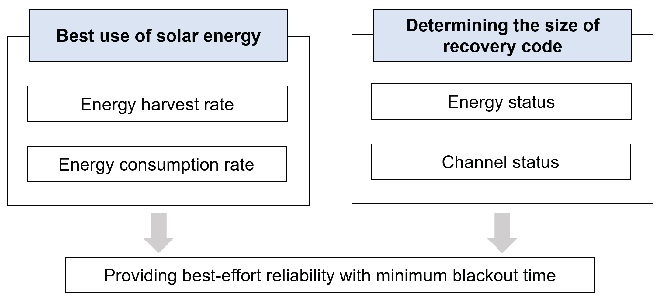
3.1. Overview
- ①
- receives a control packet containing the available energy information of from node . Then, it calculates the maximum parity size which can deal with this available energy.
- ②
- calculates the maximum parity size which can be added with its own available energy.
- ③
- Select the smaller value by comparing the parity sizes determined in step ① and step ②; this value is the best parity size in terms of energy.
- ④
- estimates the channel state between itself and through the signal strength of control packet received during step ①; then, it calculates the parity size required for the current link state.
- ⑤
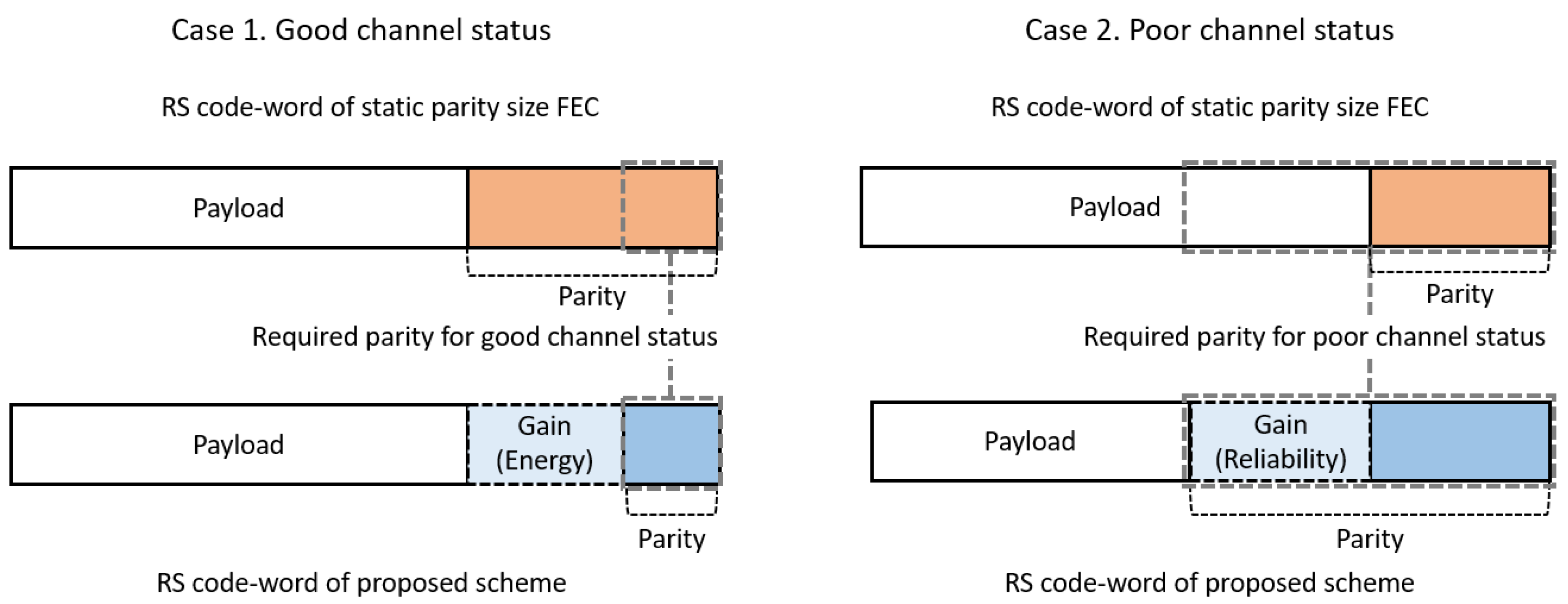
- Compare the parity size determined in step ③ with the parity size determined in step ④; if former is greater than the latter, data can be transmitted without error even if either value is finally selected. In the proposed scheme, however, the latter is selected as a final parity size to save energy. Meanwhile, in the opposite case (if the former is smaller than the latter), data transfer is abandoned in this round and delayed until the next round. This is because the errors are unlikely to be recovered even if data are transmitted by adding the maximum parity size available in terms of energy. This indicates a severe channel condition, and data transmission will be suspended until sufficient energy is available to send the data with the parity required for the link.
- ⑥
- transmits a data packet including the parity bits finally determined in step ⑤ to .
- ⑦
- recovers the error using parity bits included in the received data packet when the error is detected.
3.2. Energy Modeling
3.3. Channel-Status Modeling
3.4. Parity Size Determination According to Residual Energy
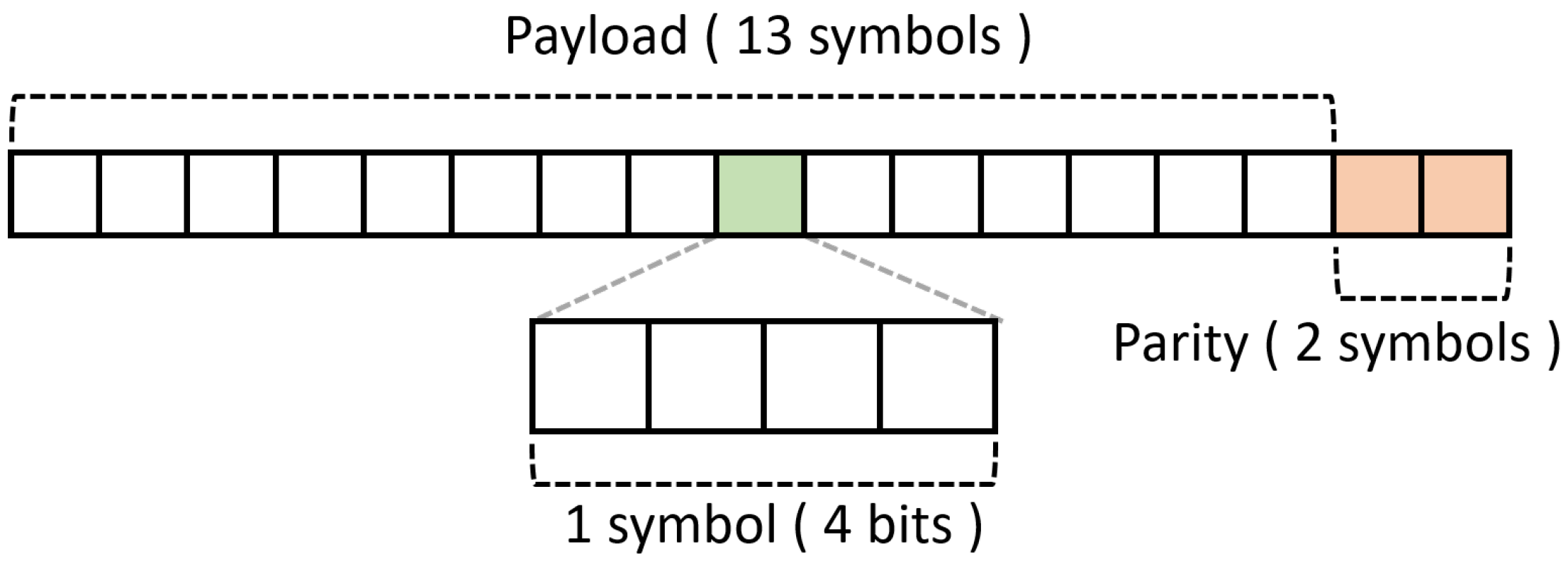
- Parity size of the transmitting node in terms of energyThe energy consumed by the transmitting node to transmit the data is calculated as follows [47]:where is the size of the data to be transmitted, is the energy consumed when transmitting one bit to a distance of one meter, d is the transmission distance and represents the path loss, the default value of which is 2; this value varies depending on the environment. In the proposed scheme, the maximum parity size that can be transmitted without exceeding the available surplus energy , calculated in Equation (5), is estimated at the beginning of the time-slot.The energy that can be used to transmit the parity is calculated as follows:where is the amount of energy consumed to send original data in the payload field, and is the amount of energy used for encoding the RS code.Please note that a symbol which consists of m bits is an operation unit of the RS scheme for encoding and transmitting. Therefore, the maximum parity symbol size that can be sent with the energy of can be represented as follows:where m is the number of bits per symbol.
- Parity size of the receiving node in terms of energyThe RS scheme consumes energy for data decoding and recovery that cannot be ignored. Assuming that the transmitting node transmits data with a long parity, considering only its energy status, the receiving node may not decode it due to insufficient energy. Therefore, when determining the parity size, the node sending the data must consider the energy of the node receiving the data, as well as its own energy.Please note that if the receiving node consumes energy exceeding , it may be blacked out. Therefore, the receiving node must limit the parity size by calculating the size of the parity that can be handled with energy . The amount of energy consumed to receive parity, excluding the energy consumed to receive data and the decoding energy , is as follows:Therefore, the maximum number of parity symbols that can be received with can be calculated as follows:where is the energy consumed when receiving one bit of data.
- Parity size determination in terms of energyAt the start of the time-slot, the receiver node embeds the information of in a control packet and transmits it to the sender. Then, the sender compares and and selects the smaller of the two as the parity candidate .
3.5. Parity Size Determination According to Channel Condition
3.6. Parity Size Selection and Data Transmission
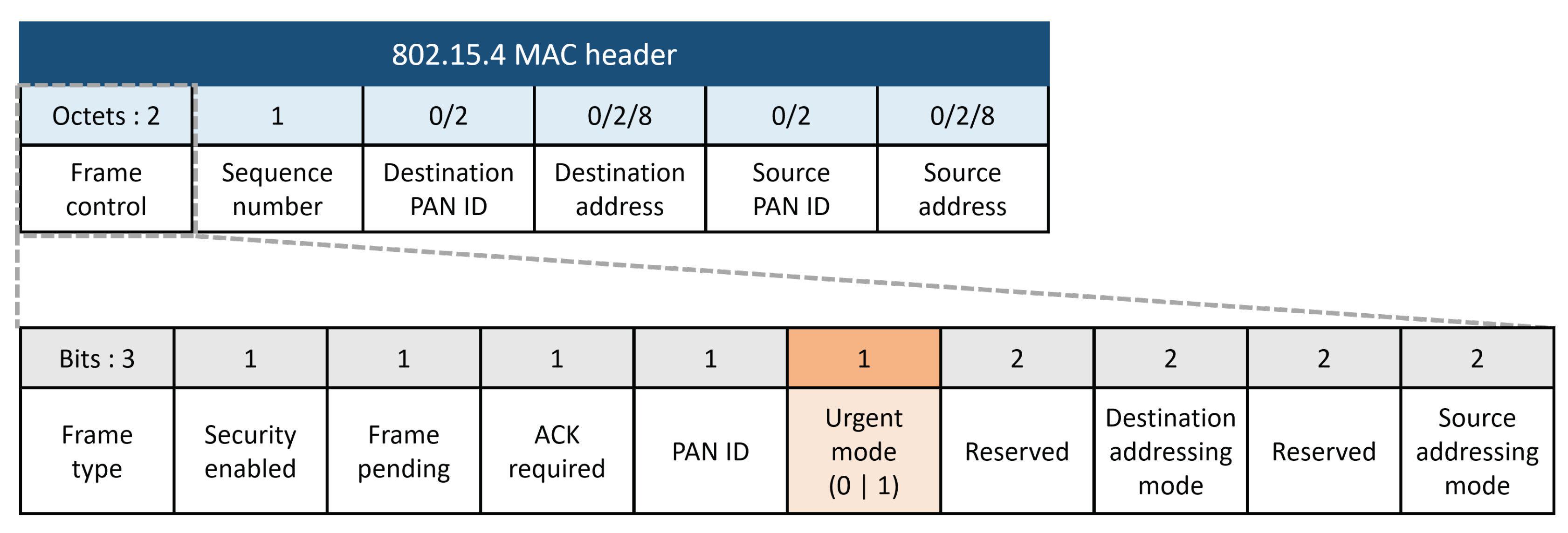
3.7. Urgent Mode to Send Emergency Data
3.8. Pseudo-Code of the Proposed Scheme
| Algorithm 1: Operation of sending node i in 1 round |
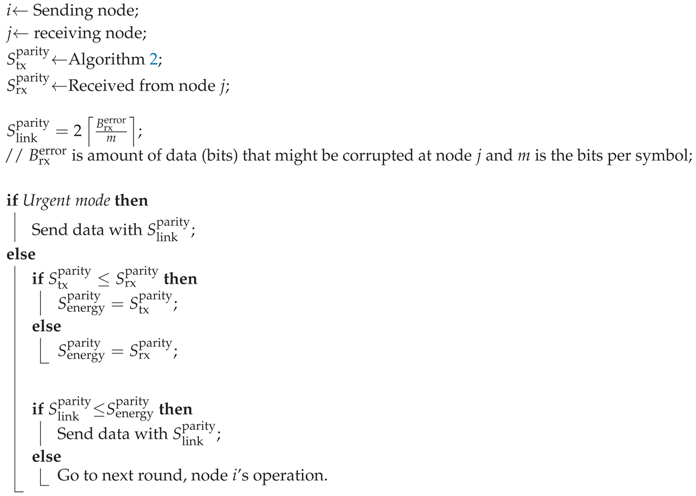 |
| Algorithm 2: Calculate of node i |
| ; ; ; return ; |
4. Performance Evaluation
4.1. Experiment Environment
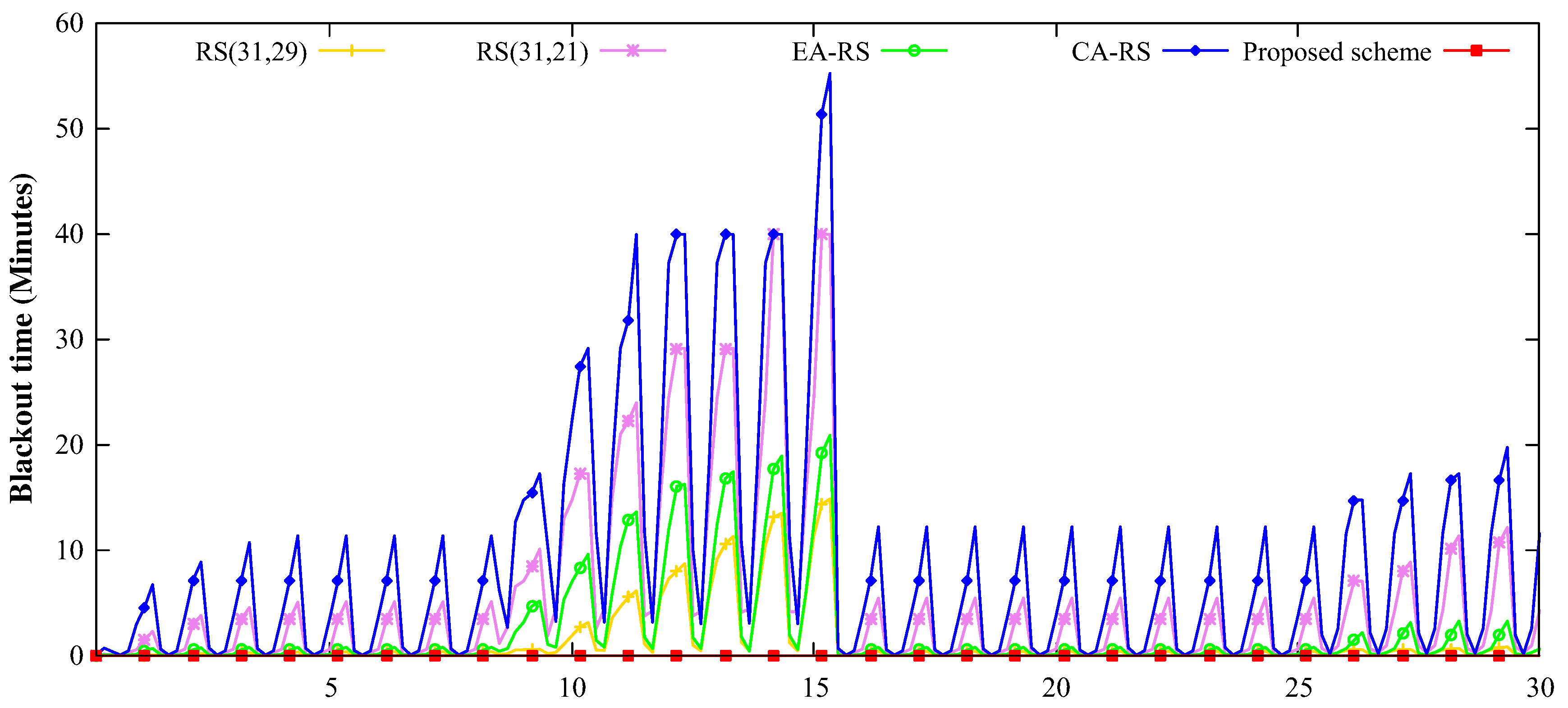
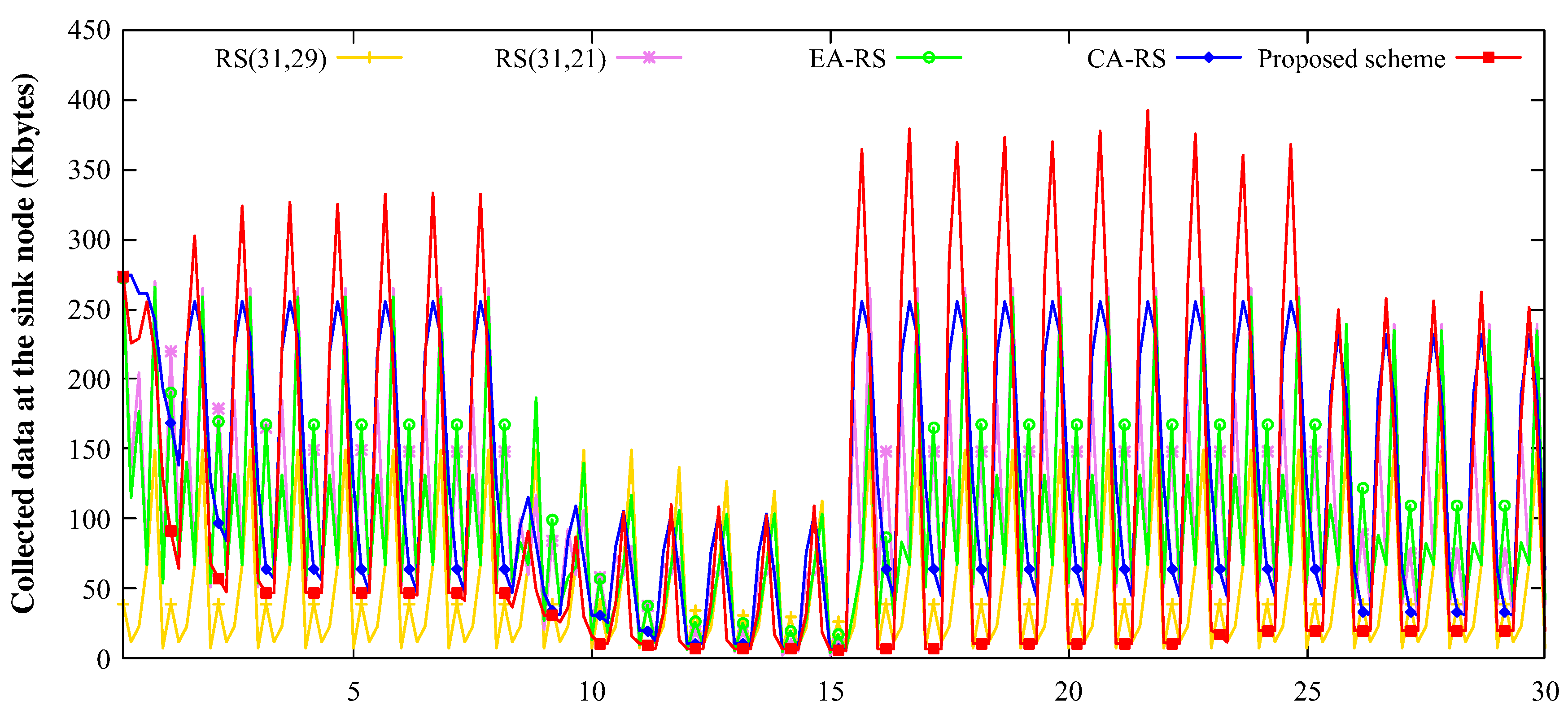
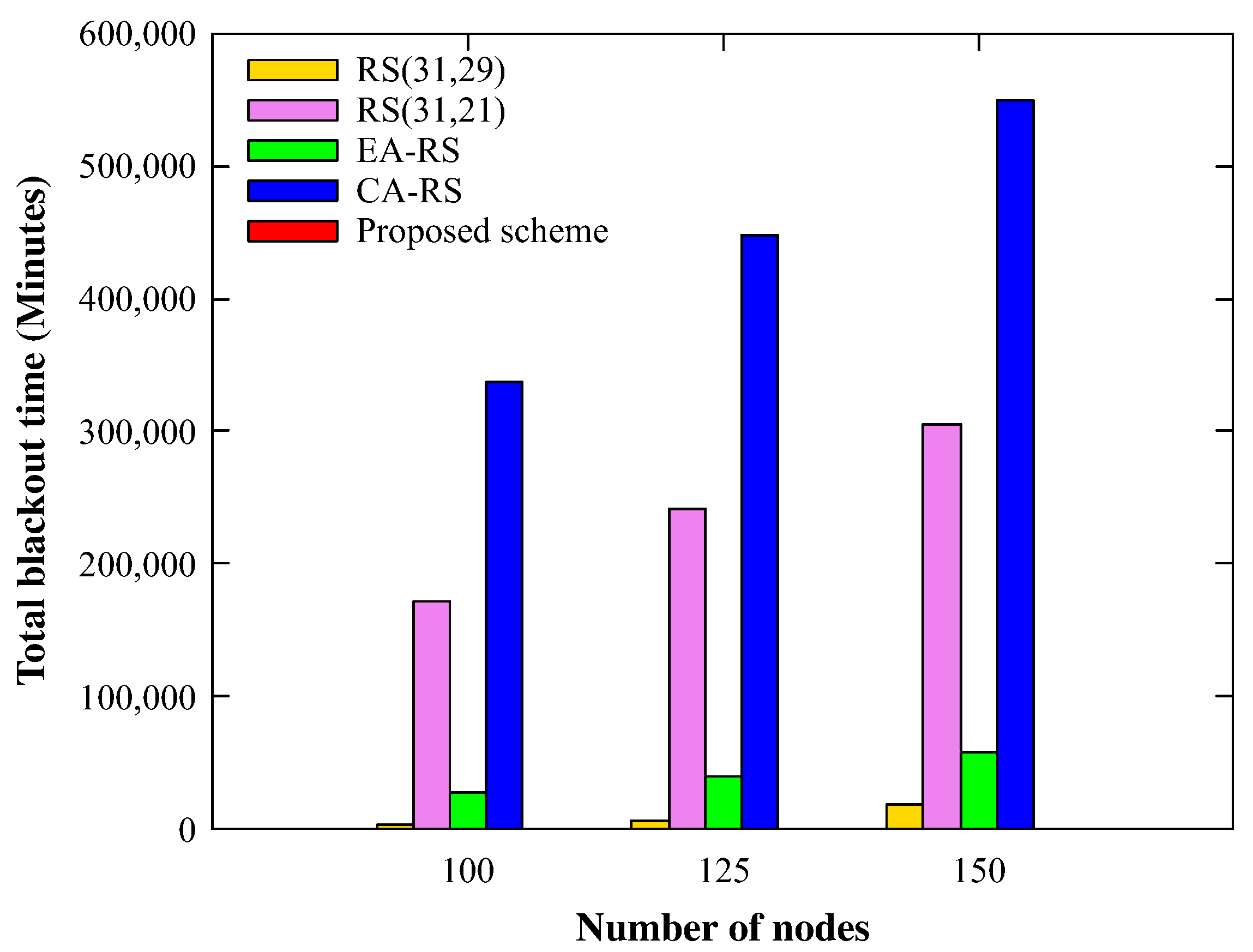
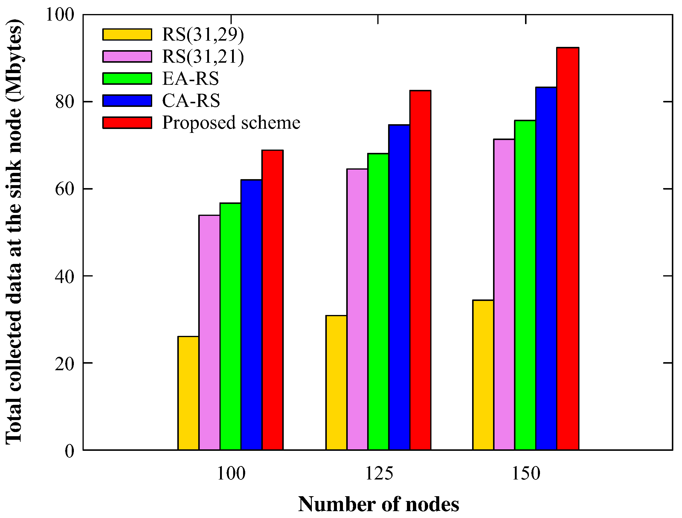
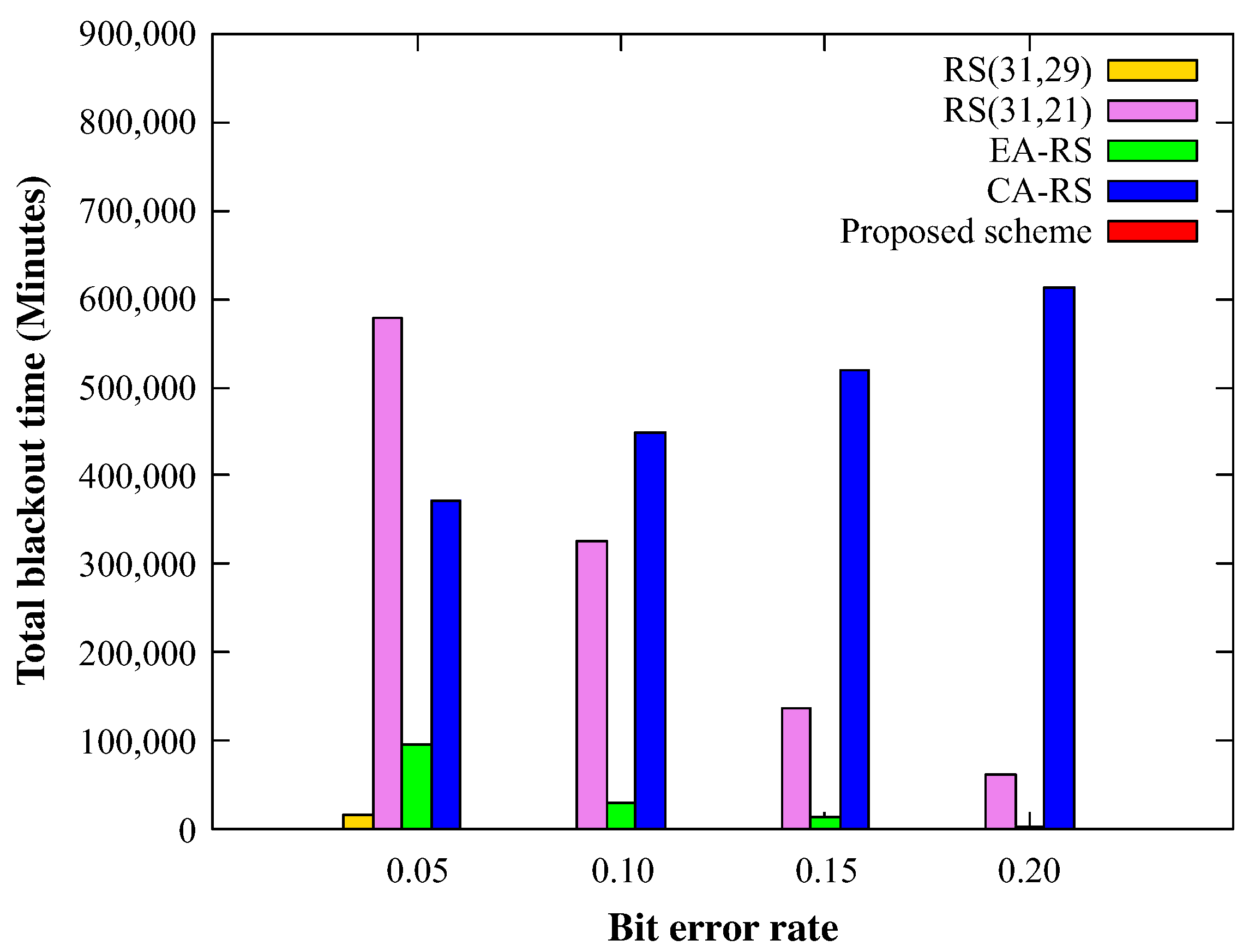
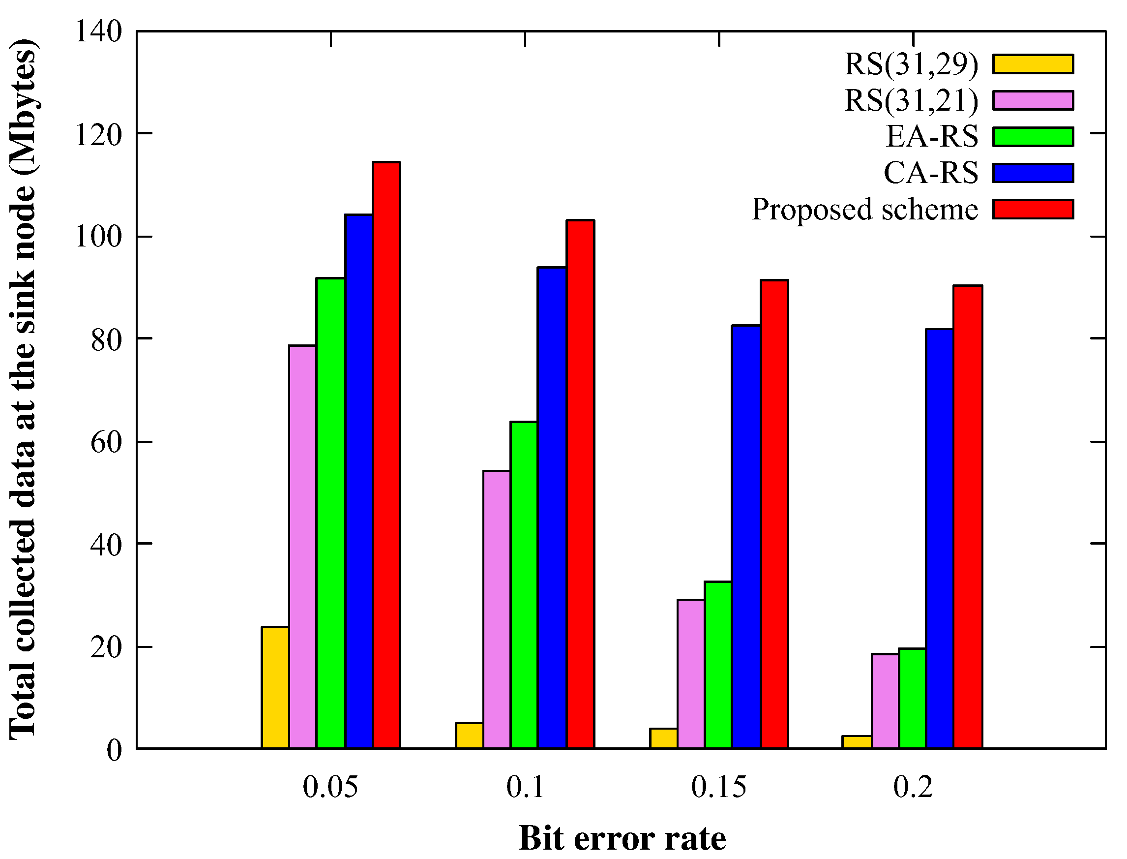
4.2. Simulation Results
5. Conclusions
Author Contributions
Funding
Conflicts of Interest
References
- Jovanovska, E.M.; Davcev, D. No pollution Smart City Sightseeing Based on WSN Monitoring System. In Proceedings of the 2020 IEEE Sixth International Conference on Mobile and Secure Services (MobiSecServ), Miami Beach, FL, USA, 22–23 February 2020; pp. 1–6. [Google Scholar]
- Adame, T.; Bel, A.; Carreras, A.; Melia-Segui, J.; Oliver, M.; Pous, R. CUIDATS: An RFID–WSN hybrid monitoring system for smart health care environments. Future Gener. Comput. Syst. 2018, 78, 602–615. [Google Scholar] [CrossRef]
- Caicedo-Ortiz, J.G.; De-La Hoz-Franco, E.; Ortega, R.M.; Piñeres-Espitia, G.; Combita-Niño, H.; Estévez, F.; Cama-Pinto, A. Monitoring system for agronomic variables based in WSN technology on cassava crops. Comput. Electron. Agric. 2018, 145, 275–281. [Google Scholar] [CrossRef]
- Behera, T.M.; Mohapatra, S.K.; Samal, U.C.; Khan, M.S.; Daneshmand, M.; Gandomi, A.H. I-sep: An improved routing protocol for heterogeneous WSN for IoT-based environmental monitoring. IEEE Internet Things J. 2019, 7, 710–717. [Google Scholar] [CrossRef]
- Tokala, M.; Nallamekala, R. Secured algorithm for routing the military field data using dynamic sink: Wsn. In Proceedings of the IEEE 2018 Second International Conference on Inventive Communication and Computational Technologies(ICICCT), Coimbatore, India, 20–21 April 2018; pp. 471–476. [Google Scholar]
- Saini, A.; Kansal, A.; Randhawa, N.S. Minimization of energy consumption in WSN using hybrid WECRA approach. Procedia Comput. Sci. 2019, 155, 803–808. [Google Scholar] [CrossRef]
- Wang, F.; Liu, W.; Wang, T.; Zhao, M.; Xie, M.; Song, H.; Li, X.; Liu, A. To reduce delay, energy consumption and collision through optimization duty-cycle and size of forwarding node set in WSNs. IEEE Access 2019, 7, 55983–56015. [Google Scholar] [CrossRef]
- Dhami, M.; Garg, V.; Randhawa, N.S. Enhanced lifetime with less energy consumption in WSN using genetic algorithm based approach. In Proceedings of the 2018 IEEE 9th Annual Information Technology, Electronics and Mobile Communication Conference (IEMCON), Vancouver, BC, Canada, 1–3 November 2018; pp. 865–870. [Google Scholar]
- Sudevalayam, S.; Kulkarni, P. Energy harvesting sensor nodes: Survey and implications. IEEE Commun. Surv. Tutor. 2010, 13, 443–461. [Google Scholar] [CrossRef] [Green Version]
- Chen, Q.; Gao, H.; Cai, Z.; Cheng, L.; Li, J. Energy-collision aware data aggregation scheduling for energy harvesting sensor networks. In Proceedings of the IEEE INFOCOM 2018-IEEE Conference on Computer Communications, Honolulu, HI, USA, 16–19 April 2018; pp. 117–125. [Google Scholar]
- Gaglione, A.; Rodenas-Herraiz, D.; Jia, Y.; Nawaz, S.; Arroyo, E.; Mascolo, C.; Soga, K.; Seshia, A.A. Energy neutral operation of vibration energy-harvesting sensor networks for bridge applications. In Proceedings of the 2018 International Conference on Embedded Wireless Systems and Networks (EWSN), Madrid, Spain, 14–16 February 2018. [Google Scholar]
- Raghunathan, V.; Kansal, A.; Hsu, J.; Friedman, J.; Srivastava, M. Design considerations for solar energy harvesting wireless embedded systems. In Proceedings of the IPSN 2005, IEEE Fourth International Symposium on Information Processing in Sensor Networks, Boise, ID, USA, 15 April 2005; pp. 457–462. [Google Scholar]
- Li, K.; Yuen, C.; Kusy, B.; Jurdak, R.; Ignjatovic, A.; Kanhere, S.S.; Jha, S. Fair scheduling for data collection in mobile sensor networks with energy harvesting. IEEE Trans. Mob. Comput. 2018, 18, 1274–1287. [Google Scholar] [CrossRef] [Green Version]
- Basagni, S.; Naderi, M.Y.; Petrioli, C.; Spenza, D.; Conti, M.; Giordano, S.; Stojmenovic, I. Wireless sensor networks with energy harvesting. In Mobile Ad Hoc Networking: Cutting Edge Directions; Basagni, S., Conti, M., Giordano, S., Stojmenovic, I., Eds.; John Wiley & Sons, Inc.: Hoboken, NJ, USA, 2013; pp. 703–736. [Google Scholar]
- Qi, N.; Dai, K.; Yi, F.; Wang, X.; You, Z.; Zhao, J. An adaptive energy management strategy to extend battery lifetime of solar powered wireless sensor nodes. IEEE Access 2019, 7, 88289–88300. [Google Scholar] [CrossRef]
- Raghunathan, V.; Schurgers, C.; Park, S.; Srivastava, M.B. Energy-aware wireless microsensor networks. IEEE Signal Process. Mag. 2002, 19, 40–50. [Google Scholar] [CrossRef]
- Akyildiz, I.F.; Su, W.; Sankarasubramaniam, Y.; Cayirci, E. Wireless sensor networks: A survey. Comput. Netw. 2002, 38, 393–422. [Google Scholar] [CrossRef] [Green Version]
- Tian, Z.; Yuan, D.; Liang, Q. Energy efficiency analysis of error control schemes in wireless sensor networks. In Proceedings of the 2008 IEEE International Wireless Communications and Mobile Computing Conference, Crete Island, Greece, 6–8 August 2008; pp. 401–405. [Google Scholar]
- Abughalieh, N.; Steenhaut, K.; Nowé, A. Low power channel coding for wireless sensor networks. In Proceedings of the 2010 17th IEEE Symposium on Communications and Vehicular Technology in the Benelux (SCVT2010), Enschede, The Netherlands, 24–25 November 2010; pp. 1–5. [Google Scholar]
- Angelin, A.; Revathi, B.; Gayathri, T.; Balakumaran, M.D. Channel coding in WSN for energy optimization. Int. J. Adv. Res. Electr. Electron. Instrum. Eng. 2014, 3, 7873–7878. [Google Scholar]
- Reed, I.S.; Solomon, G. Polynomial codes over certain finite fields. J. Soc. Ind. Appl. Math. 1960, 8, 300–304. [Google Scholar] [CrossRef]
- Yang, Y.; Wang, L.; Noh, D.K.; Le, H.K.; Abdelzaher, T.F. Solarstore: Enhancing data reliability in solar-powered storage-centric sensor networks. In Proceedings of the 7th International Conference on Mobile Systems, Applications, and Services, Krakow, Poland, 22 June 2009; pp. 333–346. [Google Scholar]
- Nolan, K.E.; Guibene, W.; Kelly, M.Y. An evaluation of low power wide area network technologies for the Internet of Things. In Proceedings of the 2016 IEEE International Wireless Communications and Mobile Computing Conference (IWCMC), Paphos, Cyprus, 5–9 September 2016; pp. 439–444. [Google Scholar]
- Petäjäjärvi, J.; Mikhaylov, K.; Pettissalo, M.; Janhunen, J.; Iinatti, J. Performance of a low-power wide-area network based on LoRa technology: Doppler robustness, scalability, and coverage. Int. J. Distrib. Sens. Netw. 2017, 13. [Google Scholar] [CrossRef] [Green Version]
- Wang, S.Y.; Chen, Y.R.; Chen, T.Y.; Chang, C.H.; Cheng, Y.H.; Hsu, C.C.; Lin, Y.B. Performance of LoRa-based IoT applications on campus. In Proceedings of the IEEE Vehicular Technology Conference, Toronto, ON, Canada, 24–27 September 2017; pp. 1–6. [Google Scholar]
- Raza, U.; Kulkarni, P.; Sooriyabandara, M. Low power wide area networks: An overview. IEEE Commun. Surv. Tutor. 2017, 19, 855–873. [Google Scholar] [CrossRef] [Green Version]
- Prauzek, M.; Konecny, J.; Borova, M.; Janosova, K.; Hlavica, J.; Musilek, P. Energy harvesting sources, storage devices and system topologies for environmental wireless sensor networks: A review. Sensors 2018, 18, 2446. [Google Scholar] [CrossRef] [Green Version]
- Adu-Manu, K.S.; Adam, N.; Tapparello, C.; Ayatollahi, H.; Heinzelman, W. Energy-Harvesting Wireless Sensor Networks (EH-WSNs) a Review. ACM Trans. Sens. Netw. (TOSN) 2018, 14, 1–50. [Google Scholar] [CrossRef]
- Sharma, H.; Haque, A.; Jaffery, Z.A. Solar energy harvesting wireless sensor network nodes: A survey. J. Renew. Sustain. Energy 2018, 10, 023704. [Google Scholar] [CrossRef]
- Engmann, F.; Katsriku, F.A.; Abdulai, J.D.; Adu-Manu, K.S.; Banaseka, F.K. Prolonging the lifetime of wireless sensor networks: A review of current techniques. Wirel. Commun. Mob. Com. 2018, 2018. [Google Scholar] [CrossRef] [Green Version]
- Ottman, G.K.; Hofmann, H.F.; Bhatt, A.C.; Lesieutre, G.A. Adaptive piezoelectric energy harvesting circuit for wireless remote power supply. IEEE Trans. Power Electron. 2002, 17, 669–676. [Google Scholar] [CrossRef] [Green Version]
- Sodano, H.A.; Inman, D.J.; Park, G. Comparison of piezoelectric energy harvesting devices for recharging batteries. J. Intell. Mater. Syst. Struct. 2005, 16, 799–807. [Google Scholar] [CrossRef]
- Simjee, F.I.; Chou, P.H. Efficient charging of supercapacitors for extended lifetime of wireless sensor nodes. IEEE Trans. Power Electron. 2008, 23, 1526–1536. [Google Scholar] [CrossRef]
- Yoon, I.; Kim, H.; Noh, D.K. Adaptive data aggregation and compression to improve energy utilization in solar-powered wireless sensor networks. Sensors 2017, 17, 1226. [Google Scholar] [CrossRef] [PubMed] [Green Version]
- Kang, M.; Yoon, I.; Noh, D.K. Efficient location service for a mobile sink in solar-powered wireless sensor networks. Sensors 2019, 19, 272. [Google Scholar] [CrossRef] [PubMed] [Green Version]
- Tunca, C.; Isik, S.; Donmez, M.Y.; Ersoy, C. Ring routing: An energy-efficient routing protocol for wireless sensor networks with a mobile sink. IEEE Trans. Mob. Comput. 2014, 14, 1947–1960. [Google Scholar] [CrossRef]
- Hamming, R.W. Error detecting and error correcting codes. Bell Syst. Tech. J. 1950, 29, 147–160. [Google Scholar] [CrossRef]
- Costello, D.J. Error Control Coding: Fundamentals and Applications; Prentice Hall: Upper Saddle River, NJ, USA, 1983. [Google Scholar]
- Bose, R.C.; Ray-Chaudhuri, D.K. On a class of error correcting binary group codes. Inf. Control 1960, 3, 68–79. [Google Scholar] [CrossRef] [Green Version]
- Berrou, C.; Glavieux, A.; Thitimajshima, P. Near Shannon limit error-correcting coding and decoding: Turbo-codes.1. In Proceedings of the ICC’93—IEEE International Conference on Communications, Geneva, Switzerland, 23–26 May 1993; Volume 2, pp. 1064–1070. [Google Scholar]
- Ahn, J.S.; Yoon, J.H.; Lee, K.W. Performance and energy consumption analysis of 802.11 with FEC codes over wireless sensor networks. J. Commun. Netw. 2007, 9, 265–273. [Google Scholar] [CrossRef]
- Wicker, S.B.; Bhargava, V.K. Reed-Solomon Codes and Their Applications; John Wiley & Sons: Hoboken, NJ, USA, 1999. [Google Scholar]
- Jung, K.K.; Choi, W.S. Performance Analysis of RS codes for Low PowerWireless Sensor Networks. J. Korea Soc. Comput. Inf. 2010, 15, 83–90. [Google Scholar] [CrossRef]
- Baccour, N.; Koubâa, A.; Mottola, L.; Zúñiga, M.A.; Youssef, H.; Boano, C.A.; Alves, M. Radio link quality estimation in wireless sensor networks: A survey. ACM Trans. Sens. Netw. (TOSN) 2012, 8, 1–33. [Google Scholar] [CrossRef]
- Rappaport, T.S. Wireless Communications: Principles and Practice; Prentice Hall: Upper Saddle River, NJ, USA, 1996; Volume 2. [Google Scholar]
- Zhang, J.; Tan, K.; Zhao, J.; Wu, H.; Zhang, Y. A practical SNR-guided rate adaptation. In Proceedings of the IEEE INFOCOM 2008—The 27th Conference on Computer Communications, Phoenix, AZ, USA, 13–18 April 2008; pp. 2083–2091. [Google Scholar]
- Melodia, T.; Pompili, D.; Akyildiz, I.F. Optimal local topology knowledge for energy efficient geographical routing in sensor networks. In Proceedings of the IEEE INFOCOM 2004, Hong Kong, China, 7–11 March 2004; Volume 3, pp. 1705–1716. [Google Scholar]
- Yi, J.M.; Kang, M.J.; Noh, D.K. SolarCastalia: Solar energy harvesting wireless sensor network simulator. Int. J. Distrib. Sens. Netw. 2015, 11, 415174. [Google Scholar] [CrossRef]
- TI CC2630. CC2630 SimpleLink™ 6LoWPAN, ZigBee® Wireless MCU Datasheet (Rev. B). Apr. 2017. Available online: http://www.ti.com/product/CC2630 (accessed on 31 July 2020).
- Jung, J.; Kang, M.; Yoon, I.; Noh, D.K. Adaptive forward error correction scheme to improve data reliability in solar-powered wireless sensor networks. In Proceedings of the 2016 IEEE International Conference on Information Science and Security (ICISS), Pattaya, Thailand, 19–22 December 2016; pp. 1–4. [Google Scholar]


| Energy Sources | Characteristics | Amount of Energy Available | Harvesting Technology | Conversion Efficiency | Amount of Energy Harvested |
|---|---|---|---|---|---|
| Solar | Ambient, uncontrollable, predictable | Solar cells | 15% | ||
| Wind | Ambient, uncontrollable, predictable | - | Anemometer | - | |
| Finger motion | Active human power, fully controllable | Piezoelectric | 7.5% | ||
| Vibrations in indoor environment | Ambient, uncontrollable, unpredictable | - | Electromagnetic induction | - |
| Node | Solar Panel Power (mW) | Solar Panel Size (inxin) | Energy Availability (mWh/day) | Storage Type | Battery Type | Battery Capacity (mAh) |
|---|---|---|---|---|---|---|
| Heliomote | 190 | 1140 | Battery | Ni-MH | 1800 | |
| HydroWatch | 276 | 139 | Battery | Ni-MH | 2500 | |
| Everlast | 450 | 2700 | Supercap (100F) | NA | NA | |
| SolarBiscuit | 150 | 900 | Supercap (1F) | NA | NA | |
| Prometheus | 130 | 780 | Supercap (two 22F) and battery | Li-poly | 200 |
| Parameter | Value |
|---|---|
| Simulation time | 30 days |
| Number of nodes | 100, 125, 150 |
| Node topology | Random |
| Weather | Randomly selected |
| Obscured node (by shadow) | Randomly select 10% of nodes |
| Field size | 2500 |
| Transmission range | 10 m |
| Channel status (BER) | 0.05, 0.1, 0.15, 0.2 |
| Baud rate | 250 kbps |
| Sensing rate | 32 bytes/min |
| Bit per symbol | 5 bits |
| Battery capacity | 100 J |
| Maximum harvested energy | 49.22 J/day |
| Minimum harvested energy | 14.77 J/day |
| Average harvested energy | 38.72 J/day |
| Transmission energy | 0.6208 nJ/byte |
| Reception energy | 0.0661 µJ/byte |
| Encoding energy | 47 µJ/symbol |
| Decoding energy | 163 µJ/symbol |
© 2020 by the authors. Licensee MDPI, Basel, Switzerland. This article is an open access article distributed under the terms and conditions of the Creative Commons Attribution (CC BY) license (http://creativecommons.org/licenses/by/4.0/).
Share and Cite
Gil, G.W.; Kang, M.; Kim, Y.; Yoon, I.; Noh, D.K. Efficient FEC Scheme for Solar-Powered WSNs Considering Energy and Link-Quality. Energies 2020, 13, 3952. https://doi.org/10.3390/en13153952
Gil GW, Kang M, Kim Y, Yoon I, Noh DK. Efficient FEC Scheme for Solar-Powered WSNs Considering Energy and Link-Quality. Energies. 2020; 13(15):3952. https://doi.org/10.3390/en13153952
Chicago/Turabian StyleGil, Gun Wook, Minjae Kang, Younghyun Kim, Ikjune Yoon, and Dong Kun Noh. 2020. "Efficient FEC Scheme for Solar-Powered WSNs Considering Energy and Link-Quality" Energies 13, no. 15: 3952. https://doi.org/10.3390/en13153952
APA StyleGil, G. W., Kang, M., Kim, Y., Yoon, I., & Noh, D. K. (2020). Efficient FEC Scheme for Solar-Powered WSNs Considering Energy and Link-Quality. Energies, 13(15), 3952. https://doi.org/10.3390/en13153952