Abstract
The central heating technology with thermal storage technology is an important means to realize thermoelectric decoupling, meet heating demand, reduce primary energy consumption, and protect the ecological environment. For this paper, the numerical simulation method was used to study the temperature variation of large-capacity hot water storage tank (HWST) in an actual combined heat and power system. The influence of various factors, including the length diameter ratio, water supply temperature, and water supply flow, as well as the orifice diameter and number of the water distributor, on the flow uniformity and performance of the HWST was investigated. The results show that the heat storage efficiency and flow uniformity of the HWST can be improved by properly increasing the water supply flow, the orifice diameter, and number of the water distributor. Increasing the length diameter ratio can improve the flow uniformity, but it will reduce the heat storage efficiency of the HWST. Increasing the water supply temperature can increase heat storage efficiency of the HWST and accelerate the stratification of cold and hot water in the tank. Besides, the comprehensive analysis of the non-dimensional exergy loss calculation results, velocity field, and temperature field show that there is a certain coupling relationship between the non-dimensional exergy loss and flow uniformity at the initial stage of heat storage. In practical application, the influence of these factors on flow uniformity, heat storage efficiency, and non-dimensional exergy loss should be comprehensively considered in order to achieve the best heat storage and release performance of the HWST. This paper provides some engineering guidance for the application of large-capacity heat storage tanks in the combined heat and power (CHP) system.
1. Introduction
In recent years, central heating, as a heat-supply way to save resources and reduce environmental pollution, has gradually become the trend of heating in China’s cities and towns under the whole circumstances of advocating energy-saving and environment-protecting at the current. Given the population of central heating in northern cities, predicted by 2025 to reach 179 million, will result in the heating area reaching 749 million m2 and the coal consumption reaching 152 million TCE (1 ton standard coal equivalent) [1]. Therefore, the energy-savings of heating system is quite indispensable to meet the increasing heating demand year by year, improve the energy utilization rate, and reduce environmental pollution.
The operation mode of cogeneration heating system in China, so far, is mainly based on thermal power plant and peaking boiler. Nevertheless, most heat users following the policy of measuring charge adopted the way of self-regulation, which results in larger fluctuation of thermal load and more obvious peak valley difference [2]. Some measures, such as adding units in the power plant and installing load adjustment boiler, were taken to meet the needs of heat users usually. However, these mean increasing the investment of the system to a certain extent, and they cannot fundamentally reduce the primary energy consumption and environmental pollution [3]. In addition, unable to be completely utilized, the plant unit will give rise to energy waste since it unable to be effective in the period of low heat consumption. Although the traditional operation mode of “power by heat” improves the economy of the plant unit, it will create the phenomenon of “thermoelectric coupling” and reduce the peak load regulation capacity of the plant unit.
Thermal energy storage (TES) is crucial to conserve and utilize energy efficiently, deal with mismatch between demand and supply, and enhance the performance and reliability of our current energy systems [4,5,6]. Setting hot water storage tank (HWST) in cogeneration can effectively bridge the gap between the heat supply and demand, increase the peak load regulation capacity of the plant unit, realize thermoelectric decoupling, and reduce primary energy consumption [7,8,9]. Most of the thermal power plants in Denmark use this technology to adjust the peak load and fill the valley. And this technology has become an important means to realize its 100% renewable energy system in the future and has attracted the attention of European countries [10,11,12,13,14].
There are many experimental and theoretical studies to investigate the technology of HWST at home and abroad. Wang et al. [15] designed a water single-tank thermocline thermal energy storage (TES) experimental system and simulated the dynamic characteristics of thermal storage/release process of thermocline in a small HWST. The heat release efficiency of different heat storage/release temperature and the change of the inclined temperature layer in different initial states were obtained. William P. Bahnfleth et al. [16,17] calculated the cylindrical water tank with octagonal water distributor through numerical simulation and experimental research and obtained the result of temperature stratification in the water tank. Abdelhak [18] studied the influence of different positions of HWST (horizontal/vertical) on temperature stratification and presented the numerical analysis for the two structures. Research suggests that the circular current or vortex is prone to occur in the heat storage tank with the horizontal structure. Savicki [19] carried out the numerical analysis to the three-dimensional temperature field and the velocity field of the horizontal cylindrical heat storage tank, given the laminar natural convection and the vertical stratification of temperature. The results show that a more effective thermal stratification can be formed by choosing the location of the inlet jet properly. The influence of the arrangement of the inlet and outlet, the flow velocity, and the placement mode on the inclined temperature layer of HWST was studied and analyzed by Fernandez [20], which lay a foundation for finding the best layout of entrances and exits. Chung et al. [21] focused on the geometric shape of the water distributor, adopted a three-dimensional unsteady calculation model to calculate and compare the effect of water distributor with two different shapes on the stratification of water tank, and concluded that Reynolds number is the main factor affecting the stratification effect. The analysis model of different working condition group was established with a cylindrical tank in vehicles with a horizontal hole distribution of bilateral, and the influence of the number of openings and the diameter of the opener, the diameter of the water distributor, and the ratio of height to diameter of the tank on the heat release performance of the regenerator was studied by Ge Zhihua [22]. The results show that there is a coupling relationship between the thickness of the thermocline and the flow velocity of the hole.
The performance of the HWST is predominantly determined by storage loss and storage time. The storage loss of the HWST mainly includes: (1) The heat loss caused by the contact and mixing of cold and hot water at the inclined temperature layer inside the HWST; (2) the heat transfer loss caused by water flow and tank body; and (3) the convective heat transfer loss between tank wall and surrounding air. The former is related to the uniformity of the inlet flow after passing through the distributor, and the latter two are mainly related to the surface temperature and heat storage time of the tank body. Therefore, in order to achieve the best heat storage and release performance, the influence of length diameter ratio (L/D), water supply temperature, water supply flow and the orifice diameter and number of water distributor on the flow uniformity, and heat storage efficiency of HWST should be comprehensively considered. In the above context, the flow uniformity and heat storage performance of the large-capacity HWST of actual thermal power unit in China were studied in this paper. Through the control variable method, the heat storage tanks with different length diameter ratio (L/D), water supply temperature, water supply flow and the orifice diameter, and number of water distributor were modeled, and the velocity and temperature field were analyzed. The research results can provide some engineering guidance for the application of large heat storage tanks in the cogeneration unit and the adjustment of heating flexibility.
2. Mathematical Model
2.1. Physical Model
In this paper, a thermal power unit HWST in China was taken as an example to analyze the performance of the HWST under different conditions. The basic device of the HWST is shown in Figure 1. This tank has a diameter of 22 m, a height of 25 m, a volume of 10,000 m3, an effective volume of 8000 m3, and operates under normal pressure. The water distributor is a split type water distributor.
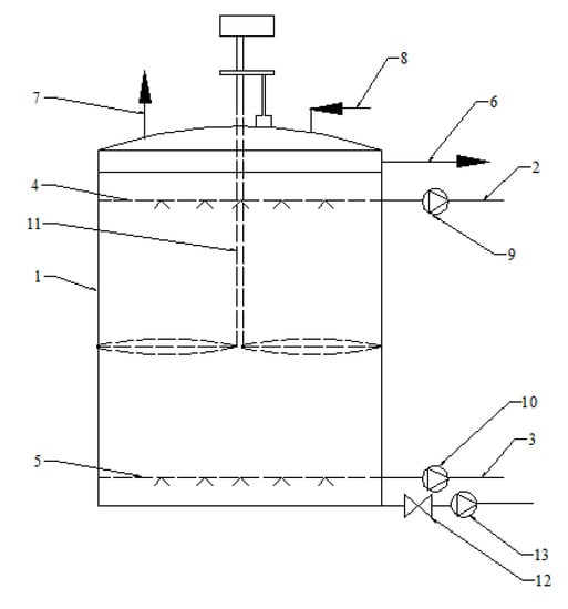
Figure 1.
Basic installation diagram of hot water storage tank (HWST). 1—tank body, 2—hot water inlet/outlet pipe, 3—cold water inlet/outlet pipe, 4—upper water distributor, 5—lower water distributor, 6—overflow pipe, 7—safety valve exhaust, 8—air intake, 9—hot water pump, 10—cold water pump, 11—scale removal device, 12—drain valve, 13—sewage pump.
2.2. Geometric and Mathematical Model
Numerical simulation analysis was carried out for the above HWST, and its geometric model was established as given in Figure 2. In order to simplify the calculation, the following assumptions are made for the geometric model of HWST under the premise of ensuring reliability:
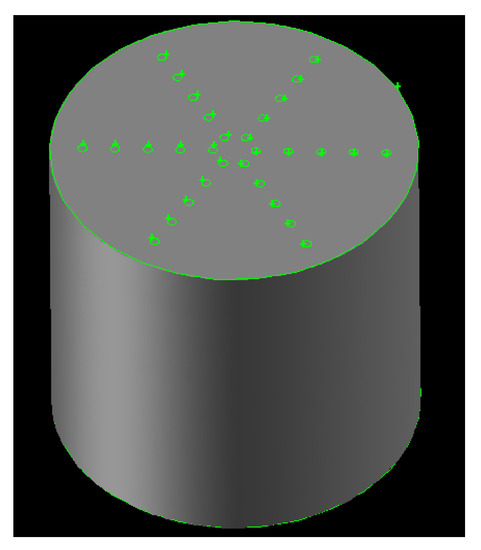
Figure 2.
Geometric model of the HWST.
- (1)
- The HWST is regarded as a closed cylinder with the arc design of the top of the HWST ignored.
- (2)
- The wall is supposed insulate as the surface heat loss caused by the convection heat transfer between the tank wall and the outside air can be ignored with the multi-layer insulation chamber equipped.
- (3)
- The volume of thermal insulation chamber is ignored.
- (4)
- The flow in the distributor has little effect on the flow in the HWST since its diameter is very small compared with the HWST, so the distributor is simplified as a circular opening.
- (5)
- The external force and internal heat source inside the tank are ignored.
- (6)
- The scale removal device in the tank is ignored since it stops running when the heat storage tank is in normal operation.
- (7)
- Assuming that the thermophysical parameters of the fluid in the tank do not change with temperature except density.
The upper water distributor is as close to the tank top as possible, and the lower water distributor is as close to the tank bottom as possible. When the heat storage tank system accumulates heat, the hot water flows in evenly from the upper distributor, and the cold water in the tank is discharged stably from the lower distributor. Then, a stable temperature interlayer, namely the inclined temperature layer, will be formed due to the density difference between the cold and hot water and the uniform water distribution function of the water distributor. In the process of heat storage, the inclined temperature layer gradually drops in the tank until it disappears. At this time, the tank is full of hot water, and the heat storage process is completed.
Based on the physical model studied in this paper, the flow at the inlet of the HWST is an incompressible three-dimensional transient turbulence. The whole simulation process meets the requirements of mass conservation (continuity equation), energy conservation, and momentum conservation. The specific formula is as follows:
Mass conservation equation:
Momentum equation:
Energy equation:
where u, v, w, are velocity components in x, y, z directions, respectively, p is the fluid pressure, is the dynamic viscosity of fluid, T is the temperature of the HWST at a certain time of operation, is the thermal conductivity of the fluid, and is the dissipation function. The above three conservation equations are discretized reasonably, and then the detailed thermal characteristics of the HWST can be obtained by numerical simulation.
The meaning and value of physical parameters in the calculation process are shown in Table 1. The simulation process is an unsteady process, the inlet of the HWST was set as velocity inlet, and the temperature was set to the actual inlet fluid temperature. The tank outlet was set as the free outlet (outflow), and the shell of the tank was set as the adiabatic boundary condition. The inlet velocity was calculated by Equation (1).

Table 1.
Value of calculation parameters.
FLUENT software was used to solve the control equation. The incompressible 3D Transient turbulence model was used in the simulation. In order to improve the accuracy of turbulent flow calculation, the standard k–ε model was used in this paper. PISO (Pressure-Implicit with Splitting of Operators) was selected as the treatment method of pressure-velocity coupling. The discrete format of pressure space is PRESTO, the spatial discretization scheme of momentum equation and energy equation is the second-order upwind difference scheme, and the iterative convergence residual value of each parameter is 10−3. The time step was set to 0.01 s after several trials.
2.3. Validation
The whole computational domain was meshed with tetrahedral-unstructured cells, and the number of grids is 704,158, 1,626,119, and 2,144,272, respectively. Through numerical calculation, when the heat storage time is 4 h, the average outlet temperature is 362.55 K, 366.01 K, and 366.39 K, respectively. That the change rate of the latter two is only 0.1% can be considered in that the average outlet temperature will not change significantly when the grid numbers exceeds 1,626,119, which indicates that the grid numbers have met the reliability of the calculation results. Therefore, the model with grid numbers of 1,626,119, considering the accuracy and time of the calculation, was used to study the characteristics of the HWST.
In order to ensure the accuracy of the numerical calculation results, the numerical simulation results are compared with the actual operation conditions of the thermal storage tank in the power plant. Figure 3 shows the model validation analysis diagram. No. 1, 4, 5, 6, and 7 are the comparison results of simulated value and actual value during heat storage under the corresponding condition in Figure 3. Compared with the actual value and simulation value, all the errors are within 5%. The results show that the calculation model has high reliability and accuracy and can reflect the heat storage/release characteristics of the HWST correctly. Therefore, the model can be used for further research on the heat storage tank.
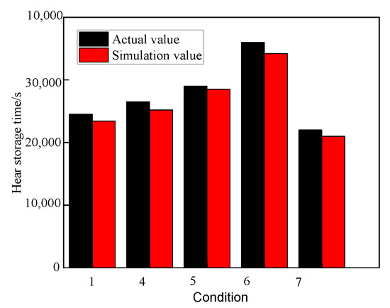
Figure 3.
Diagram of model validation analysis.
2.4. Variable Condition
For this paper, the influence of various factors, including the length diameter ratio, water supply temperature, and water supply flow, as well as the orifice diameter and number of water distributor, on the flow uniformity and performance of the HWST was investigated, and the specific parameters in the simulation are shown in Table 2.
Table 2.
Simulation parameters of variable conditions.
3. Results and Discussion
3.1. Heat Storage Efficiency
The main factors that affect the heat storage efficiency of heat storage tank are the heat loss caused by the heat dissipation of heat storage tank to surrounding environment, the mixing of cold and hot water in the inclined temperature layer and its internal heat conduction. For this paper, the heat storage efficiency was mainly used to measure the amount of heat that the tank loses to the outside world.
The heat loss caused by heat dissipation of heat storage tank to surrounding environment (Qs) is calculated by Formula (2):
Then, the heat storage efficiency formula of heat storage tank in a heat storage cycle can be calculated from Formula (3):
where V0, Tb, τ are the volume, the surface temperature, and one heat storage cycle time of the heat storage tank, respectively. T0 is the ambient temperature and α is the heat loss coefficient. The value is 0.16 KJ/(m3 s °C). The heat storage capacity (Q) of the HWST can be calculated from Formula (4):
where V is the effective volume of heat storage tank, Th is the temperature of hot water in the tank, and Tc is the temperature of cold water in the tank. When the heat storage tank is full of hot water, the heat storage capacity of the tank reaches the maximum value. According to Formula (4), the maximum effective heat storage capacity is 353.15 mWh. From Formula (3), in order to improve the thermal efficiency of the heat storage tank, not only necessary insulation measures should be taken for the tank body, but also the heat storage time can be reduced. Reducing the heat storage time, that is, increasing the heat storage times of the heat storage tank in the effective time, can reduce the heat loss coefficient and improve the heat storage efficiency. Figure 4 shows the simulation results of the change of average outlet water temperature with the heat storage time under different conditions. It can be found that the overall trend of outlet temperature is constant at first and then gradually increases with time in the process of heat storage. When the cold water inside the tank is completely discharged, the outlet temperature tends to be constant. According to Formulas (2)–(4), the calculation results of heat storage efficiency of the HWST under different conditions are shown in Table 3. It can be observed that increasing the length diameter ratio will lead to the increase of heat storage time in the case of a certain volume, thus increasing the heat dissipation and reducing the heat storage efficiency. The increase of water supply temperature will lead to increasing water temperature difference between supply and return water when the return water temperature is constant, which not only increases the heat storage time and heat loss but also increases the heat storage capacity of the heat storage tank. However, the increasing proportion of heat storage capacity is greater than the heat loss, so the heat storage efficiency is improved. Furthermore, the increase of water supply flow rate increases the inflow velocity, thus shortening the overall heat storage time, reducing the heat loss to the external environment and improving the heat storage efficiency. Besides, the heat storage time can be shortened, and the heat storage efficiency can be improved, by properly increasing the orifice diameter and the orifice number of water distributor. Therefore, on the premise of ensuring the manufacturing feasibility of the water separator, the pore diameter and the number of openings can be appropriately increased in practical application.
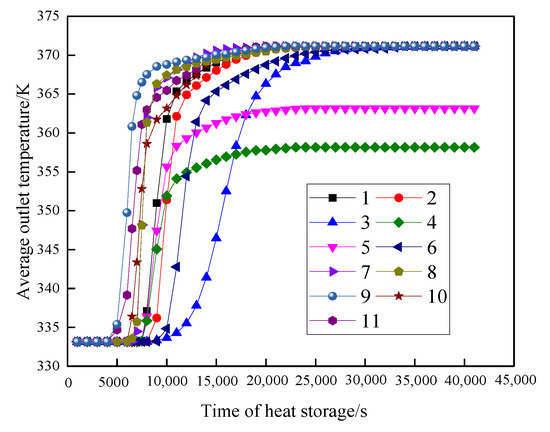
Figure 4.
Performance of HWST under different conditions.
Table 3.
The calculation results of heat storage efficiency of the HWST under different conditions.
3.2. Velocity Field Variation and Flow Uniformity
In the process of heat storage in the HWST, hot water enters the tank through the upper water distributor, while cold water flows out through the lower water distributor. The flow of hot/cold water inside the HWST will affect the formation of the inclined temperature layer, so it is very important to know the change of velocity field inside the HWST.
Figure 5 shows the velocity streamline diagram of symmetry plane under same water supply flow (2500 t/h). It can be seen that there is an annular flow under the inlet distributor and near the wall. With the development of the heat storage process, the annular flow under the distributor becomes less and less obvious, while the annular flow near the wall becomes larger and larger. In the initial stage, the formation of annular flow is due to the collision between a downward motion generated by the momentum of water flow at the entrance and an upward motion caused by thermal disturbance between the upper and lower water layers. With the heat storage time going on, the annular flow under the water distributor gradually decreases, and the flow uniformity becomes better and better. After forming a stable thermocline layer, the water flow will flow downward.
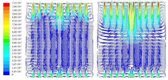
Figure 5.
Velocity streamline diagram of symmetry plane under same water supply flow (2500 t/h).
The change of velocity field at the distance of 2 m from the entrance was investigated when the heat storage time is 700 s under different factors, as shown in Figure 6. It is found that all factors have obvious influence on the velocity field at the inlet of HWST except for the water supply temperature. The disturbance of water flow will affect the temperature stratification in the tank. In order to form a good and stable temperature layer, it is necessary to ensure the flow uniformity of each section under the distributor and the smaller inlet velocity. The flow uniformity percentage (E) refers to the ratio of the area of average velocity (SE) to the total area (S) of a certain section of the HWST, which was calculated by Equation (5).
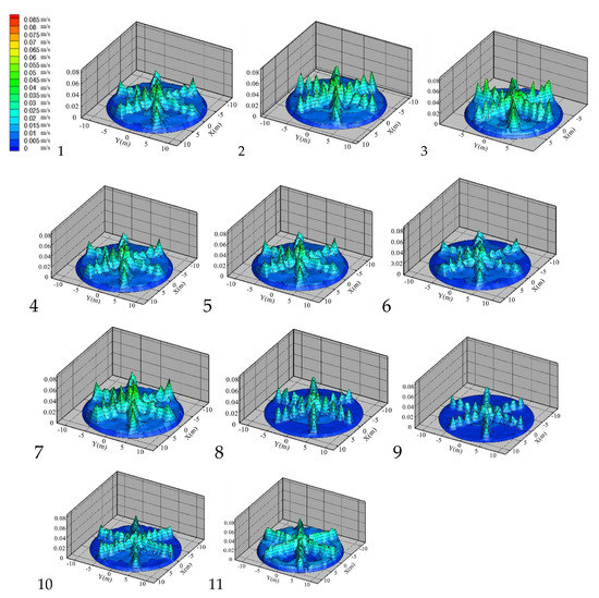
Figure 6.
Velocity field affected by different factors.
The average velocity here refers to the average velocity of a cross section simulated by fluent, and its area can be obtained by post-processing the velocity simulation data by Tecplot software. Table 4 is a comparative analysis of the calculation results of the influence of different factors on the flow uniformity of the HWST at the distance of 2 m from the entrance. From that, the flow uniformity of the HWST can be improved by properly increasing the L/D, reducing the water supply flow, and increasing the orifice diameter and the orifice number of the water distributor. And the flow uniformity of the HWST changes little under different water supply temperatures, which implies that the water supply temperature does not affect the flow uniformity in the HWST.
Table 4.
Comparative analysis of the calculation results of the influence of different factors on the flow uniformity of the HWST.
3.3. The Distribution of Temperature Field
Figure 7 and Figure 8 show the simulation cloud chart of temperature change of HWST under different factors when the storage time is 100 s and 300 s, respectively. The results show that the length diameter ratio, water supply temperature, water supply flow and the orifice diameter, and number of water distributor will affect the temperature field in the HWST. When the storage time is 100 s, the length diameter ratio and water supply temperature have no obvious effect on the mixing of cold and hot water in the HWST, while the water supply flow and the orifice diameter and number of water distributor have a strong impact on the mixing of cold and hot water. With the increase of heat storage time, the influence of various factors on the mixing and stratification of hot and cold water in the HWST becomes more and more obvious. With the increase of length diameter ratio, water supply temperature, water flow rate and the orifice diameter, and number of water distributor, the mixing time of hot and cold water in the HWST was shortened, and the formation speed of obvious stratification of hot and cold water increases.
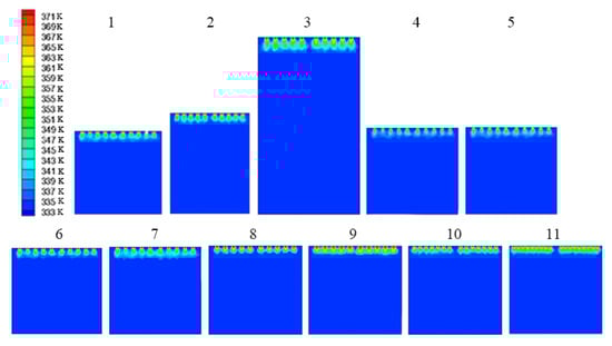
Figure 7.
Temperature nephogram under different factors when the heat storage time is 100 s.
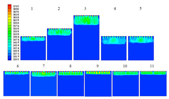
Figure 8.
Temperature nephogram under different factors when the heat storage time is 300 s.
3.4. Exergy Analysis
In order to describe the available heat loss caused by the mixing of hot and cold water and heat conduction, the non-dimensional exergy loss form is introduced here. The non-dimensional exergy loss can be defined as [23]:
where E, Emix, and Est represent the transient exergy of natural stratification, complete mixing, and complete stratification of cold and hot water in the HWST, respectively. Considering both density and specific heat constant, the instantaneous exergy difference between natural stratification and complete mixing can be evaluated as:
where and represent the average volume temperature and the equivalent temperature in a naturally stratified tank, respectively, which are evaluated as follows:
and
Similarly, the instantaneous exergy difference between complete stratification and complete mixing can be evaluated as:
where and are evaluated as follows:
Figure 9 shows the calculation results of non-dimensional exergy loss (ζ). In the early stage of heat storage/release, the cold and hot water mix strongly, and the actual value in the tank is closer to the complete mixing state, so the non-dimensional exergy loss is large. However, with the evolution of heat storage time, the temperature difference between the inlet water flow and the water in the tank gradually disappears. At this time, the decrease speed of the overall exergy value gradually slows down, indicating that the actual stratification state has been reached. In the later stage of heat storage/release, the thermocline gradually moved closer to the lower distributor, and the value of non-dimensional exergy loss began to increase. The disturbance of outlet water flow on the thermocline gradually increased, and the actual stratification state began to approach the fully mixed state until the thermocline was completely discharged. The larger the water supply flow and the orifice diameter and number of water distributor, the greater the non-dimensional exergy loss in the initial stage of heat storage/release. There is a coupling relationship between non-dimensional exergy loss and flow uniformity at the initial stage of heat storage and release here. In the initial stage of heat storage and release, the larger the non-dimensional exergy loss, the more serious the mixing of hot and cold water is, the better the flow uniformity is, and the faster the stratification of hot and cold water is. Therefore, the heat storage efficiency, flow uniformity, and non-dimensional exergy loss should be considered comprehensively to select the appropriate water supply flow and the orifice diameter and number of water distributor in practical application.
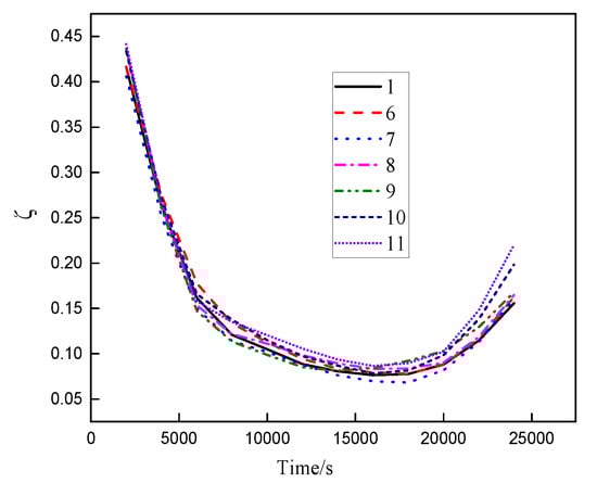
Figure 9.
The calculation results of non-dimensional exergy loss.
4. Conclusions
Hot water heat storage technology can make the system realize thermoelectric decoupling, so as to meet the demand of external heat load, improve energy utilization and reduce environmental pollution, so its development prospect is relatively broad. In order to master the heat storage and release characteristics of hot water heat storage technology and better guide the design and application of hot water heat storage tank in practical engineering, the flow field and temperature field of the HWST with water distributor were simulated, and the heat storage characteristics of the HWST under different factors were studied. The main conclusions are as follows:
- (1)
- Although increasing the length diameter ratio properly can improve the flow uniformity in the HWST, it will lead to the prolongation of the heat storage time and reduce the heat storage efficiency.
- (2)
- Although the water supply temperature has no obvious effect on the fluid flow uniformity in the HWST, it will affect the stratification speed of hot and cold water with heat storage time increasing. In addition, the heat storage capacity and heat storage efficiency of the HWST will be improved by properly increasing the water supply temperature.
- (3)
- Increasing the water supply flow and the orifice diameter and number of water distributor will increase the flow uniformity and the heat storage efficiency of the HWST.
- (4)
- Through comprehensive observation of the non-dimensional exergy loss calculation results, velocity field and temperature field, the water supply flow and the orifice diameter, and number of water distributor have great influence on the disturbance between hot and cold water in the initial stage of heat storage and release. With the increase of water supply flow and the orifice diameter and number of water distributor, the mixing speed of cold and hot water is accelerated, and then the non-dimensional exergy loss increases. Besides, there is a certain coupling relationship between the non-dimensional exergy loss and flow uniformity at the initial stage of heat storage and release. In the initial stage of heat storage and release, the larger the non-dimensional exergy loss, the more serious the mixing of hot and cold water is, the better the flow uniformity is, and the faster the stratification of hot and cold water is.
Author Contributions
Y.L., Q.Z. designed the study, established the mathematical model, and conducted the numerical study; X.C., W.Y. meshed the grids of HWST; Y.L. wrote the manuscript; F.S., X.C. reviewed the paper. All authors have read and agreed to the published version of the manuscript.
Funding
This research received no external funding.
Conflicts of Interest
The authors declare no conflict of interest.
Nomenclature
| t | Operation time of heat storage tank, h; |
| x | Transverse distance of the HWST at a certain time, m; |
| y | Longitudinal distance of the HWST at a certain time, m; |
| z | Vertical distance of the HWST at a certain time, m; |
| u | Transverse velocity of the HWST at a certain time, m/s; |
| v | Longitudinal velocity of the HWST at a certain time, m/s; |
| w | Flow velocity in the vertical direction of the HWST at a certain time, m/s; |
| w0 | Rated vertical flow rate of HWST operation, m/s; |
| τ | One cycle time of the heat storage tank, s; |
| p | Pressure, Pa; |
| R | Bottom radius of heat storage tank, m; |
| T | Temperature of the HWST at a certain time of operation, °C; |
| Th | Hot water temperature of the HWST at a certain time, °C; |
| Tc | Cold water temperature of the HWST at a certain time, °C; |
| cp | Specific heat capacity of water at constant pressure, kJ/(kg · K) |
| V0 | The volume of heat storage tank, m3; |
| η | The heat storage efficiency |
| Ti | The outlet temperature, K; |
| H | Height of heat storage tank, m; |
| Th | Hot water temperature of the HWST at a certain time, °C; |
| Q | Heat storage capacity of the heat storage tank, mWh; |
| V | The effective volume of heat storage tank, m3; |
| α | The heat loss coefficient, kJ/ (m3 s °C); |
| Ta | The ambient temperature, °C; |
| Tb | The surface temperature of the heat storage tank, °C; |
| q | The mass flow of the fluid entering the heat storage tank, t/h; |
| n | The orifice number of water distributor; |
| ζ | The non-dimensional exergy; |
References
- Zhang, L.; Han, M.; LU, X.Q. Analysis on Coal Consumption and Potential Energy-saving of Central Heating in Northern Provinces of China Under Urbanization Background. China Popul. Resour. Environ. 2015, 25, 58–68. [Google Scholar]
- Qin, B.; Fu, L.; Jiang, Y. Electric Peak Shaving for CHP Plant by U sing Thermal Inertia of Heat-supply System. Gas Heat 2005, 25, 6–8. [Google Scholar]
- Nuytten, T.; Claessens, B.; Paredis, K.; Van Bael, J.; Six, D. Flexibility of a combined heat and power system with thermal energy storage for district heating. Appl. Energy 2013, 104, 583–591. [Google Scholar] [CrossRef]
- Li, C.; Li, Q.; Zhao, Y.; Cong, L.; Jiang, Z.; Li, Y.; Ding, Y. Composite phase change materials for thermal energy storage: From molecular modelling based formulation to innovative manufacture. Energy Procedia 2019, 158, 4510–4516. [Google Scholar] [CrossRef]
- Liu, C.; Rao, Z. Challenges in various thermal energy storage technologies. Sci. Bull. 2017, 62, 231–233. [Google Scholar] [CrossRef]
- Erdemir, D.; Altuntop, N. Improved thermal stratification with obstacles placed inside the vertical mantled hot water tanks. Appl. Therm. Eng. 2016, 100, 20–29. [Google Scholar] [CrossRef]
- Lyu, Q.; Chen, T. Analysis on peak-load regulation ability of cogeneration unit with heat accumulator. Autom. Electr. Power Syst. 2014, 38, 34–41. [Google Scholar]
- Lund, H.; Andersen, A.N. Optimal designs of small CHP plants in a market with fluctuating electricity prices. Energy Convers. Manag. 2005, 46, 893–904. [Google Scholar] [CrossRef]
- Wang, K.; Tian, H.M.; Jia, J. Expanding the Peak Regulation Margin of Heating Unitsby Using Heat Storage Technology. Energy Conserv. Technol. 2012, 30, 339–341. [Google Scholar]
- Pillai, J.R.; Bak-Jensen, B. Integration of Vehicle-to-Grid in the Western Danish Power System. IEEE Trans. Sustain. Energy 2010, 2, 12–19. [Google Scholar] [CrossRef]
- Lund, H.; Mathiesen, B.V. Energy system analysis of 100% renewable energy systems—The case of Denmark in years 2030 and 2050. Energy 2009, 34, 524–531. [Google Scholar] [CrossRef]
- d’Entremont, A.; Corgnale, C.; Sulic, M.; Hardy, B.; Zidan, R.; Motyka, T. Modeling of a thermal energy storage system based on coupled metal hydrides (magnesium iron-sodium alanate) for concentrating solar power plants. Appl. Therm. Eng. 2010, 30, 1255–1261. [Google Scholar] [CrossRef]
- Andersen, A.N.; Lund, H. CHP-Plants with Big Thermal Stores Balancing Fluctuating Productions from Wind Turbines. Available online: http://desire.iwes.fraunhofer.de/files/deliverables/del_4.1-4.4.pdf (accessed on 2 June 2013).
- Alanne, K. Sustainable small-scale CHP technologies for buildings: The basis for multi-perspective decision-making. Renew. Sustain. Energy Rev. 2004, 8, 401–431. [Google Scholar] [CrossRef]
- Wang, X.; He, Z. Dynamic Simulations on Simultaneous Charging/Discharging Process of Water Thermocline Storage Tank. Proc. CSEE 2019, 39, 5989–5998. [Google Scholar]
- Musser, A.; Bahnfleth, W.P. Parametric study of charging inlet diffuser performance in stratified chilled water storage tanks with radial diffusers: Part1-model development and validation. HVAC R Res. 2001, 7, 31–49. [Google Scholar] [CrossRef]
- Bahnfleth, W.P.; Song, J. Constant flow rate charging characteristics of a full-scale stratified chilled water storage tank with double-ring slotted pipe diffusers. Appl. Therm. Eng. 2005, 25, 3067–3082. [Google Scholar] [CrossRef]
- Abdelhak, O.; Mhiri, H.; Bournot, P. CFD analysis of thermal stratification in domestic hot water storage tank during dynamic mode. Build. Simul. 2015, 8, 421–429. [Google Scholar] [CrossRef]
- Savicki, D.L.; Vielmo, H.A.; Krenzinger, A. Three-dimensional analysis and investigation of the thermal and hydrodynamic behaviors of cylindrical storage tanks. Renew. Energy 2011, 36, 1364–1373. [Google Scholar] [CrossRef]
- Fernández-Seara, J.; Uhı, F.J.; Sieres, J. Experimental analysis of a domestic electric hot water storage tank. Part II: Dynamic mode of operation. Appl. Therm. Eng. 2007, 27, 137–144. [Google Scholar] [CrossRef]
- Chung, J.D.; Cho, S.H.; Tae, C.S.; Yoo, H. The effect of diffuser configuration on thermal stratification in a rectangular storage tank. Renew. Energy 2008, 33, 2236–2245. [Google Scholar] [CrossRef]
- Ge, Z.; Zhang, F.; Zhang, Y. Simulation on Performance Improvement of Single Thermocline Energy Storage Tank. Proc. CSEE 2019, 39, 773–781. [Google Scholar]
- Consul, R.; Rodrıguez, I.; Perez-Segarra, C.D.; Soria, M. Virtual prototyping of storage tanks by means of three-dimensional CFD and heat transfer numerical simulations. Sol. Energy 2007, 77, 179–191. [Google Scholar] [CrossRef]


© 2020 by the authors. Licensee MDPI, Basel, Switzerland. This article is an open access article distributed under the terms and conditions of the Creative Commons Attribution (CC BY) license (http://creativecommons.org/licenses/by/4.0/).