Article

Pore-Filled Anion-Exchange Membranes with Double Cross-Linking Structure for Fuel Cells and Redox Flow Batteries

Department of Green Chemical Engineering, College of Engineering, Sangmyung University, Cheonan 31066, Korea
*
Author to whom correspondence should be addressed.
Energies 2020, 13(18), 4761; https://doi.org/10.3390/en13184761
Submission received: 19 August 2020 / Revised: 4 September 2020 / Accepted: 10 September 2020 / Published: 11 September 2020

Abstract

:
In this work, high-performance pore-filled anion-exchange membranes (PFAEMs) with double cross-linking structures have been successfully developed for application to promising electrochemical energy conversion systems, such as alkaline direct liquid fuel cells (ADLFCs) and vanadium redox flow batteries (VRFBs). Specifically, two kinds of porous polytetrafluoroethylene (PTFE) substrates, with different hydrophilicities, were utilized for the membrane fabrication. The PTFE-based PFAEMs revealed, both excellent electrochemical characteristics, and chemical stability in harsh environments. It was proven that the use of a hydrophilic porous substrate is more desirable for the efficient power generation of ADLFCs, mainly owing to the facilitated transport of hydroxyl ions through the membrane, showing an excellent maximum power density of around 400 mW cm−2 at 60 °C. In the case of VRFB, however, the battery cell employing the hydrophobic PTFE-based PFAEM exhibited the highest energy efficiency (87%, cf. AMX = 82%) among the tested membranes, because the crossover rate of vanadium redox species through the membrane most significantly affects the VRFB efficiency. The results imply that the properties of a porous substrate for preparing the membranes should match the operating environment, for successful applications to electrochemical energy conversion processes.

Graphical Abstract

1. Introduction

Ion-exchange membranes (IEMs), which can selectively transport counter ions having the opposite charge to the fixed charge groups, and connected to the membrane matrix by means of the Donnan exclusion, have been widely utilized in many desalination processes such as electrodialysis (ED) [1,2,3], diffusion dialysis (DD) [4,5], membrane capacitive deionization (MCDI) [6,7,8], etc. Recently, IEMs have also been successfully applied in several electrochemical energy production and storage systems, including fuel cells (FCs) [9,10,11,12,13], reverse electrodialysis (RED) [14,15], redox flow batteries (RFBs) [16,17,18,19] and so on. Particularly, proton-exchange membranes (PEMs), such as Nafion, have been widely utilized in energy conversion processes, owing to their excellent proton conductivity and chemical stability [20].
Among various energy conversion systems, the application to fuel cells has been the most actively researched. As is well known, there are several types of fuel cells, depending on the kinds of electrolytes used and operation conditions, including the proton-exchange membrane fuel cell (PEMFC), alkaline fuel cell (AFC), phosphoric acid fuel cell (PAFC), molten carbonate fuel cell (MCFC), solid oxide fuel cell (SOFC), and direct methanol fuel cell (DMFC) [21]. Recently, alkaline direct liquid fuel cells (ADLFCs), utilizing liquid fuels and anion-exchange membranes (AEMs), have also attracted a lot of interest as one of promising energy production systems [22]. Like traditional alkaline fuel cells, ADLFCs have several attractive features, such as operation at relatively low temperature, fast electrode reaction (oxygen reduction reaction (ORR) at cathode), use of nonprecious metal catalysts, low fuel crossover, easy water management, and so on [22,23,24]. In addition, as liquid fuels, alcohols such as methanol, ethanol, and glycerol have been the most widely studied [24]. The use of formate alkaline solutions as liquid fuels for ADLFCs has recently attracted much attention because it can realize efficient power sources for portable electronic devices [11,25]. They can provide several benefits over alcohols, e.g., fast oxidation kinetics, theoretically high cell potential and power densities, and low fuel crossover [25,26]. AEMs are one of the key components determining the energy conversion performances of ADLFCs. Therefore, various studies have been conducted to develop high-performance AEMs for successful applications to alkaline membrane fuel cells. In particular, structural studies on the polymer backbone and anion-exchange groups are being carried out [27,28]. In addition, the state-of-the-art commercial AEMs such as Tokuyama A201 and A901 exhibited excellent performance in alkaline energy conversion processes, including AFCs [28], alkaline water electrolysis [29], and alkali metal-air batteries [30]. For example, the AFCs employing Tokuyama A901 achieved high power density of around 450 mW cm−2 at specific conditions [28]. Unfortunately, however, the ion conductivity of AEMs is significantly lower compared to that of PEMs (e.g., Nafion), and the chemical stability should also be further improved for practical applications.
Meanwhile, RFBs are one of the prospective large-scale electricity storage technologies and require efficient membranes for separating different redox species [31]. Among many kinds of RFBs, all-vanadium redox flow batteries (VRFB), in which vanadium redox species are used as the active electrode materials, have been the most actively researched and utilized due to advantages, such as long battery cycle life, reduced cross-contamination, high electrochemical activity, and so on [32,33]. The ideal membranes for VRFB should possess low vanadium ion permeability to reduce self-discharge and achieve high coulomb efficiency (CE), low area resistance to decrease losses in voltage efficiency (VE), and excellent chemical stability [34]. However, even though perfluorinated PEMs such as Nafion have been widely used as a separator in VRFBs, owing to their high proton permeability and chemical stability, they suffer from the significant crossover of cationic redox species during operation, which can result in a decrease in the battery efficiency [32]. In addition, the employment of expensive perfluorinated PEMs such as Nafion could significantly elevate the system cost [33]. Among various approaches to solving this problem, the use of AEMs has received much attention due to their low permeability of cationic species by the Donnan exclusion effect, and potentially low membrane cost [33,34]. To be successfully used in VRFB, however, their poor chemical stability in harsh acidic environments, and relatively low ion conductivity should be further enhanced [33]. For example, the ion conductivity of Tokuyama A201 is shown to be about 42 mS cm−1 [29] which is much smaller than that of Nafion (86 mS cm−1 for Nafion 1035 [35]).
Among the various kinds of IEMs, pore-filled IEMs (PFIEMs), which are composed of a thin and mechanically strong porous substrate film, and polyelectrolyte that fills the pores, are known to provide both the high ion conductivity and mechanical strength [36,37,38,39]. They could also be fabricated by a simple and cheap manufacturing process [39]. Recently, we have developed novel pore-filled AEMs (PFAEMs) for application to electrochemical energy conversion systems [11]. The results demonstrated that the PFAEMs, consisting of a thin porous polytetrafluoroethylene (PTFE) substrate and highly cross-linked ionomer, could provide both excellent electrochemical properties and alkaline stability [11]. Unfortunately, however, the power generation was much poorer than those of the state-of-the-art such as the Tokuyama A901 [28].
In this work, we have dramatically improved the performances of the PFAEMs by choosing a proper porous substrate and adjusting the cross-linking degree for successful applications to ADLFC and VRFB. Namely, two different kinds of porous PTFE substrate, i.e., hydrophobic and hydrophilic grades, were chosen and utilized for the comparative study, and membrane cross-linking was also finely controlled. Moreover, we have systematically characterized the prepared membranes via various experimental analyses, including membrane-electrode assembly (MEA) tests, VRFB charge-discharge tests, Fenton oxidation, vanadium oxidative stability, and crossover rate evaluations, etc.

2. Materials and Methods

2.1. Materials and Membrane Preparation

Two different grades of highly porous PTFE film (i.e., hydrophobic and hydrophilic grades, Advantec MFS, Inc., Tokyo, Japan) were employed as the substrates for preparing PFAEMs. The specifications of the porous PTFE substrates are listed in Table 1, showing the almost identical pore dimensions. N,N’-Dimethylaminoethyl methacrylate (DMAEMA) and divinylbenzene (DVB) were chosen as the main monomer and cross-linker, respectively. p-Xylylene dichloride (XDC) was used for both the quaternization and cross-linking of the polymer, and benzophenone (BP) was selected as the initiator for the photo-polymerization. The reaction scheme of DMAEMA-DVB copolymer, which is cross-linked and quaternized by XDC, is suggested in Figure 1. As shown in the scheme, the synthesized ionomer has a double cross-linking structure by DVB and XDC, realizing a high cross-linking degree and ion-exchange capacity, at the same time. For the membrane preparation, first, monomer mixtures consisting of 79–98 wt% DMAEMA, 1–20 wt% DVB, and 1 wt% BP were prepared. Porous PTFE substrate was then dipped in the monomer solution for several hours, followed by a photo-induced polymerization in a lab-made ultraviolet (UV) chamber (high pressure, lamp power = 1 kW) for 10 min. For the successive quaternization and cross-linking, the PTFE substrate filled with poly(DMAEMA-DVB) was immersed in 0.05 M XDC-EtOH solution at 50 °C for 12 h and then sequentially treated with 0.5 M NH4Cl, 0.5 M HCl, and distilled water. The fabricated PFAEMs were then immersed in 0.5 M NaCl or 1.0 M KOH before evaluation. All the reagents were supplied by Sigma-Aldrich (St. Louis, MO, USA) and utilized as received. We also chose Neosepta® AMX (Astom Corp., Tokyo, Japan) as the reference membrane to compare with the PFAEMs fabricated in this work.

2.2. Membrane Characterizations

The synthesis of the anion-exchangeable polymer was confirmed by FT-IR (FT/IR-4700, Jasco, Tokyo, Japan) analysis. The morphological characteristics of the porous substrates and prepared PFAEMs were investigated by employing field emission scanning electron microscopy (FE-SEM, TESCAN, Czech). The surface hydrophilicity of the membranes was also evaluated using a contact angle analyzer (Phoenix 150, SEO Co., Suwon-si, Korea). The water uptake (WU) of the membranes was determined using the following equation:
WU   ( % ) = ( W w e t W d r y W d r y ) × 100
where Wdry and Wwet are the dry and wet membrane weights, respectively. A traditional titration method was employed to determine the ion-exchange capacity (IEC) of the membranes. After the pre-equilibrium in 0.5 M NaCl, chloride ions in the membrane were fully exchanged with sulfate ions in 0.25 M Na2SO4. The amount of Cl was then quantitatively analyzed by titration with an AgNO3 standard solution, and the IEC values were calculated using the following equation:
IEC   ( meq . / g dry memb ) = N Cl V s W d r y
where NCl is the normal concentration of Cl (meq./L), Vs is the solution volume (L), and Wdry is the dry membrane weights (g). Both the ion conductivity (σ) and electrical area resistance (EAR) of the membranes were evaluated in a 1.0 M KOH solution at room temperature using a lab-made clip cell and an LCZ meter. The σ values were obtained from the following equation:
σ ( S / cm ) = l R m e m b A
where Rmemb is the resistance (Ω), l is the thickness (cm), and A is the effective area (cm2) of the tested membrane. The EAR was estimated using the following equation:
EAR   ( Ω   cm 2 ) = ( | Z | s a m p l e c o s θ sample | Z | b l a n k c o s θ blank ) A
where |Z| is the magnitude of impedance (Ω), θ is the phase angle, and A is the effective area (cm2) of the tested membrane. The transport number (t) for counter ions (Cl) was obtained by measuring the cell potential (=electromotive force, emf) using a two-compartment cell (membrane area = 0.785 cm2; each volume = 0.23 dm3) equipped with a pair of Ag/AgCl reference electrodes. As a result, the t values were determined by the following equation:
E m = R T F ( 1 2 t ) ln a L a H
where Em is the cell potential, F the Faraday constant, T the absolute temperature, R the molar gas constant, and aH and aL the activity in high and low concentration compartments, respectively. The alkaline stability of the membranes was evaluated by conventional soaking tests under a harsh alkaline environment (1 M KOH; 60 °C; 500 h). The oxidative stability of the membranes was also checked by soaking experiments using Fenton’s reagent (3% H2O2 containing 2 ppm FeSO4) at 80 °C for 6 h. The time-course changes in the transport number and membrane weight were recorded to evaluate the alkaline and oxidative stabilities, respectively. The fuel (hydrazine, N2H4) crossover rates through the membranes were estimated via conventional 2-compartment diffusion cell tests. The time-course change in N2H4 content in the low concentration compartment was quantitatively analyzed using UV/Vis spectroscopy (UV-2600i, Shimadzu Co., Kyoto, Japan). The diffusion coefficient (D) of N2H4 through a membrane was calculated by the following equation [16]:
D ( cm 2 / s ) = d C L d t δ V L A ( C H C L )
where t is the time, δ is the membrane thickness, VL is the low concentration compartment volume, A is the membrane area, and CH and CL are the molar concentrations, in high and low concentration compartments, respectively. In addition, the overall dialysis coefficient (KA) of vanadium cations through a membrane was determined using a two-compartment cell (effective area = 4 × 4 cm2), filled with 1 M VOSO4/2.0 M H2SO4 (feed) and 1 M MgSO4/2.0 M H2SO4 (permeate). During the tests, the time-course change in vanadyl (VO2+) ion concentration in the permeate compartment was recorded by measuring the solution absorbance using UV/Vis spectroscopy. The KA values were determined from the dependence of the component concentration and volume changes upon time, using the following equation [40]:
ln c A 0 I c A 0 I 1 + k V k V c A I I = 1 + k V k V A V I I K A τ
where c A 0 I is the initial molar concentration of component A in the feed compartment. c A I and c A I I are the molar concentrations of component A in the feed (I) and permeate (II) compartments, respectively. A is the membrane area, τ is time, V I and V I I are the solution volume in the feed (I) and permeate (II) compartments, respectively, and k v is the solution volume ratio of both compartments (= V I / V I I ). In this work, the vanadium oxidative stability of the membranes was also confirmed. The membrane specimens (2 × 2 cm2) were immersed in 0.1 M V2O5 solution (in 5 M H2SO4) and stored at 40 °C for about 200 h to evaluate the oxidative stability of membranes in a vanadium electrolyte solution. The time-course change in the oxidation state of vanadium ions was monitored by measuring the solution absorbance using UV/Vis spectroscopy [41].

2.3. MEA Performance Tests (ADLFC)

A lab-made Ni/C [2] and Pt/C (46.7%, Tanaka Co., Tokyo, Japan) were chosen as anode and cathode electrocatalysts, respectively. The electrocatalyst solutions were directly sprayed on the surface of the membranes (3 × 3 cm2; OH-form), and the total loading amount of Ni and Pt was revealed to be about 2 mg cm2 and 1 mg cm2, respectively. As a binder in the electrocatalyst inks, commercially available anion-exchange ionomer (AS-4, Tokuyama Co., Tokyo, Japan) was utilized. The catalyst-coated membrane (CCM) was inserted between two sheets of carbon fiber composite paper (TGP-H-060, Toray Inc., Tokyo, Japan) used as a gas diffusion layer (GDL). The CCM and GDLs were then assembled with a clamping pressure of about 5.5 MPa. The current–voltage (IV) polarization characteristics of the prepared MEAs were investigated using a single cell, having an effective area of 9 cm2 at 60 °C. Liquid fuel (4 M N2H4/4 M KOH) and humidified O2 gas (of 100% relative humidity (RH)) were fed to the anode and cathode at the flow rate of 5 mL min−1 and 500 sccm, respectively. In addition, for the IV polarization curve measurement, a current was stepped up by 0.01 A and then maintained for 30 s at each step to gain a stable response.

2.4. Charge-Discharge Tests (VRFB)

2 M V2(OSO4)3 in 3 M H2SO4 (as anolyte) and 2 M VOSO4 in 3 M H2SO4 (as catholyte) were employed as the electrolyte solutions to evaluate the charge–discharge performance in the VRFB systems utilizing various membranes. The galvanostatic charge–discharge experiments were performed utilizing a lab-made RFB cell (membrane area = 12.5 cm2) containing a pair of carbon felt electrodes (GF20-3, Nippon Graphite, Otsu-shi, Japan) with a battery cycler (WBCS3000S, Wonatech, Seoul, Korea) in the potential range of 0.9–1.9 V at 0.25 A. All the tests were carried out at room temperature.

3. Results and Discussion

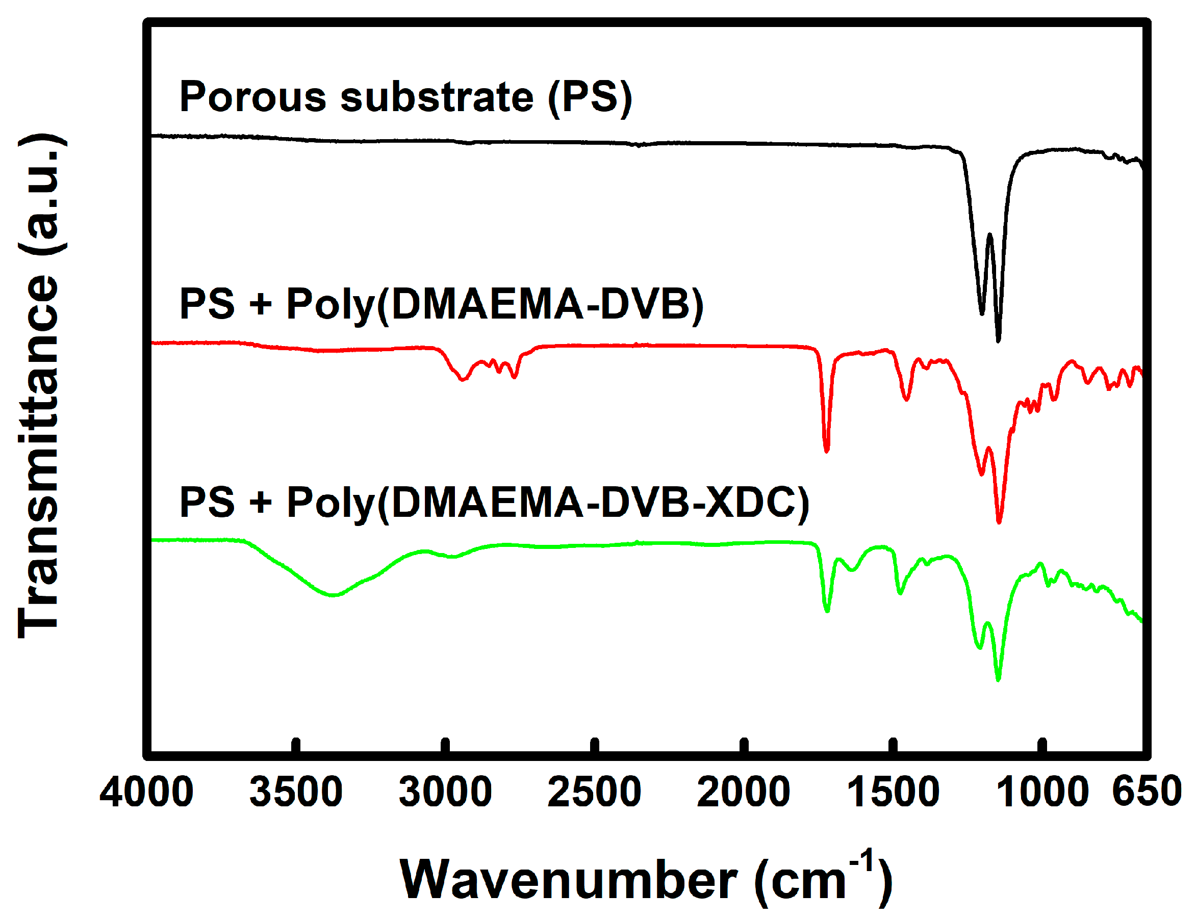
Figure 2 shows the FT-IR spectra of the porous PTFE substrate and prepared membranes. In the spectra of both the base membrane (PS + Poly(DMAEMA-DVB)) and PFAEM (PS + Poly(DMAEMA-DVB-XDC)), the absorption bands at 1726 cm−1 and 1456 cm−1, which are assigned to the stretch vibration of carbonyl group (C=O), and the C=C in plane stretch vibration of the benzene ring, respectively, indicating the successful in situ synthesis of poly(DMAMEA-DVB) inside the pores of the PTFE substrate [42]. In addition, the absorption band at around 3400 cm−1, which is assigned to the stretching vibration of the N-H+ group clearly elucidates the introduction of quaternary ammonium sites into the membrane [42].
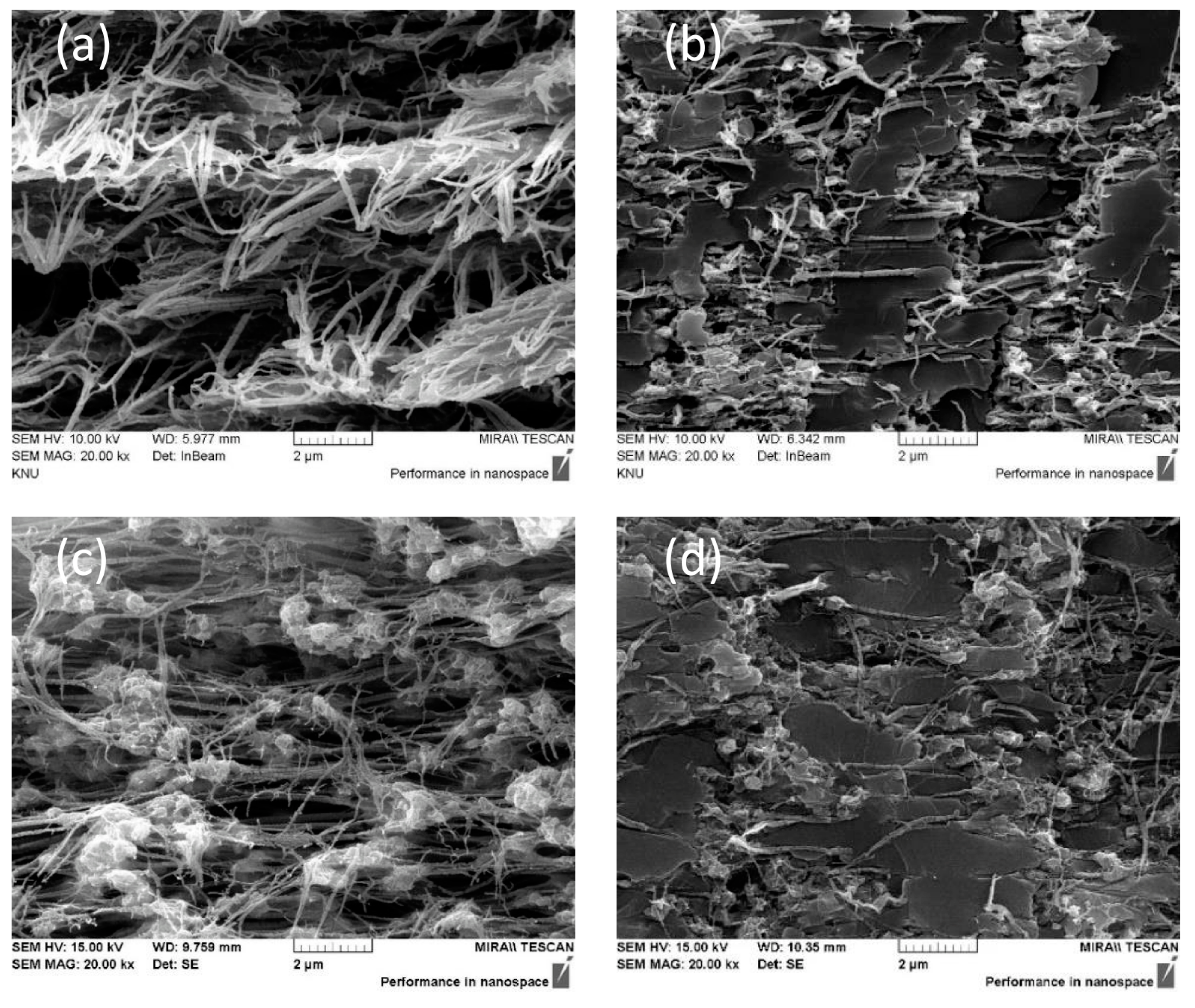
The FE-SEM analyses were carried out to investigate the morphology and pore-filling of the membranes and the images are shown in Figure 3. The cross-sectional FE-SEM images of the PTFE substrate films show a highly porous structure, and the pores in the substrates were revealed to be completely filled with ionomer after the membrane fabrication. In addition, nano-sized metal oxide particles (e.g., Al2O3) were observed in the images of hydrophilic PTFE-based samples (Figure 3c,d), which might enhance the hydrophilicity of the substrate and membrane [43]. The pictures of the porous substrates and prepared membranes are shown in Figure S1 (in the Supplementary Materials). The opaque porous substrates were shown to be changed into a transparent state after the pore-filling by in situ polymerization.
In this work, the cross-linking of the PFAEMs was finely controlled by varying the cross-linker (DVB) contents. Some important membrane parameters (i.e. IEC, ER, contact angle, and WU) were correlated with the cross-linker content and the results are depicted in Figure 4a–d. As the DVB content increased, the IEC and WU values were shown to decrease, while the EARs and surface contact angles increased, demonstrating the reduction of free volume and number of hydrophilic fixed charges in the membranes. The images of the surface contact angle measurements are also displayed in Figure S2 (in the Supplementary Materials). The IECs of the PFAEMs fabricated with different porous PTFE substrate films (i.e., hydrophobic and hydrophilic grades) were almost the same at the identical membrane composition, as shown in Figure 4a. This result could prove that the pore size and porosity of the substrate films used, are comparable with each other. However, the PFAEMs prepared using a hydrophilic PTFE substrate (i.e., hydrophilic-PFAEMs) showed much lower EARs compared with those of the hydrophobic PTFE-based PFAEMs (i.e., hydrophobic-PFAEMs), meaning more facilitated ion transport through the more hydrophilic medium. The EAR values of the hydrophilic-PFAEMs started to sharply increase when adding the cross-linker of above 10 wt%, as shown in Figure 4b. Therefore, the optimal cross-linker content was determined as 10 wt%.
The various properties of the PFAEMs, which were fabricated with different porous substrate films and identical monomer composition (10 wt% DVB), are compared with those of the commercial membrane (AMX) in Table 2. Note that the same PFAEMs have also been utilized for comparative studies in ADLFC and VRFB systems. The surface contact angles of the PTFE based PFAEMs are shown to be much higher than that of the commercial membrane. Meanwhile, the contact angle of the hydrophilic-PFAEM is much smaller than that of the hydrophobic-PFAEM. This is one of the intrinsic characteristics of pore-filling types of membranes employing an inert porous substrate, that is, the hydrophobic nature of the porous substrate dominates the surface contact angles. The IEC values of the compared membranes were almost the same as each other, while the hydrophilic PFAEM revealed much higher conductivity for hydroxyl ions than those of both the hydrophobic-PFAEM and commercial membrane. As a result, the EAR of the hydrophilic-PFAEM was shown to be reduced by about four times compared with that of both the hydrophobic-PFAEM and the commercial membrane, because of the relatively high conductivity and thin membrane thickness. The prepared membranes exhibited excellent transport numbers for an anion (Cl), which were superior to that of the commercial membrane. Moreover, the alkaline stability of the AEMs was also checked via soaking tests under a harsh alkaline condition (i.e., 1 M KOH/60 °C/500 h). The transport numbers of the AEMs were shown to be significantly reduced after the alkaline soaking tests. The decrement in the transport numbers could have mainly originated from the degradation of quaternary ammonium sites under a harsh alkaline environment. The decrease in the transport number of the PTFE-based PFAEMs was much smaller than that of the commercial membrane, demonstrating that both, the use of chemically stable PTFE substrates, and the highly cross-linked ionomer, could largely enhance the alkaline stability of the membranes. The oxidative stability of the commercial and prepared membranes was also evaluated with the soaking experiment, using Fenton’s reagent (3% H2O2 containing 2 ppm FeSO4). As shown in Table 2 and Figure 5, the chemical stabilities of the PFAEMs were superior to that of the commercial membrane. The result demonstrates that the combination of a chemically stable PTFE substrate and a highly cross-linked hydrocarbon ionomer significantly enhances the chemical stability of the membranes. In addition, the differences in the chemical stability of the two PFAEMs were not that significant.
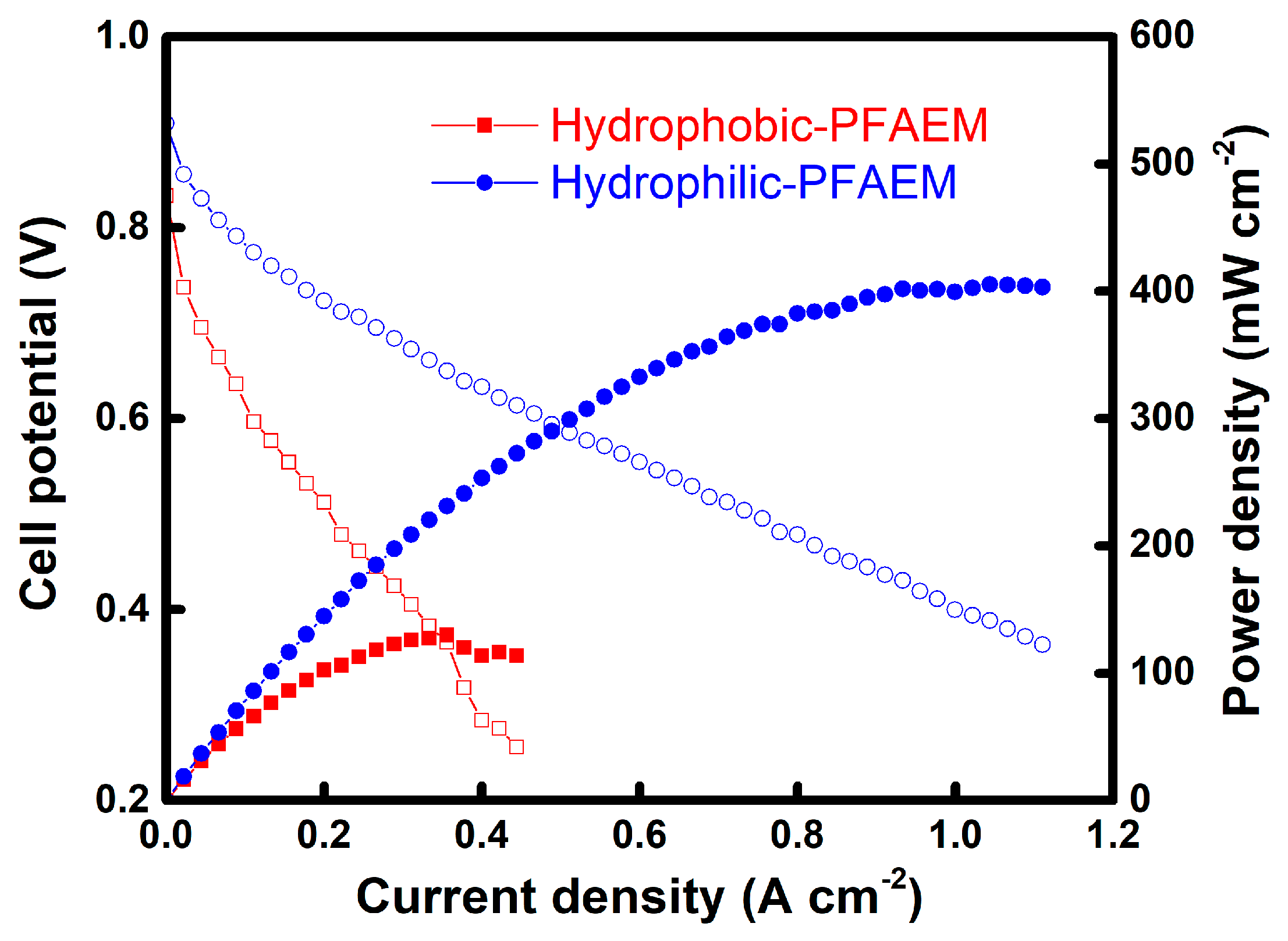
The MEAs utilizing two different PFAEMs were evaluated by the IV polarization test, using a liquid fuel of 4 M KOH and 4 M N2H4 at 60 °C and 100% RH. The IV and current–power (IP) polarization curves of the MEAs are displayed in Figure 6. As a result, the power generation performance of the MEA was dramatically improved by employing the hydrophilic membrane instead of the hydrophobic one. The maximum power density of the MEA employing the hydrophilic-PFAEM was shown to be about 400 mW cm−2 at 1 A cm−2. This result is almost comparable with that of the state-of-the-art membranes such as the Tokuyama A901 [28]. Since the crossover of liquid fuel through a membrane largely affects the energy conversion efficiency in such types of fuel cell [44], we also evaluated the diffusion coefficients of N2H4 through the PFAEMs, by means of conventional two-compartment diffusion cell tests. As shown in Table 3, the diffusion coefficient of the fuel molecule through the hydrophilic-PFAEM was revealed to be somewhat higher than that of the hydrophobic-PFAEM. It is believed that the more hydrophilic nature of the membrane increases the diffusion rate of the hydrophilic molecules. This means that the energy conversion efficiency of the hydrophilic-PFAEM is expected to be poorer than that of the hydrophobic-PFAEM, in terms of the fuel crossover rate. Therefore, it could be concluded that the dramatic improvement of the power density by employing the hydrophilic-PFAEM mainly resulted from the facilitated hydroxyl ion transport through the membrane.
VRFB experiments were also performed to investigate the influence of the membranes on the battery characteristics, as shown in Figure 7. The charge—discharge performances were revealed to be largely affected by the membrane properties, and the efficiencies are summarized in Table 4. The hydrophobic-PFAEM showed the highest value of coulombic efficiency (CE) among the membranes tested, indicating that the crossover of redox species through the membrane was effectively suppressed owing to its high cross-linking degree and hydrophobic nature. The crossover rate of vanadyl ions (VO2+) through the membranes could be estimated from a two-compartment diffusion cell experiment, by recording the time-course change of VO2+ concentration (Figure 8). The overall dialysis coefficient (KA) values calculated from Equation (7) are also summarized in Table 4. The hydrophobic-PFAEM showed almost similar KA values, despite its considerably reduced thickness compared to that of the commercial AMX membrane. However, the hydrophilic-PFAEM revealed a KA value increased by about three times, owing to its hydrophilic nature and much-reduced thickness compared to the hydrophobic-PFAEM. As a result, it can be seen that the lowest CE value of the hydrophilic-PFAEM among the membranes compared, is due to the high crossover rate of the vanadium redox species. On the other hand, the hydrophilic-PFAEM exhibited the highest voltage efficiency (VE) among the membranes tested, due to the lowest mass transport resistance (note the data in Table 2). Overall, the VRFB employing the hydrophobic-PFAEM showed the highest energy efficiency (EE), of about 87%. In the case of ADLFC, it was preferable to use a hydrophilic-membrane because ion conductivity was the most critical factor determining the efficiency of the system. However, unlike ADLFC, the crossover of the redox species through the membrane more significantly influenced the system efficiency in VRFB. Therefore, in this case, it was found that the employment of a hydrophobic-PTFE-based PFAEM can result in a more improved energy efficiency.
The soaking tests for the membranes were also conducted in 0.1 M V2O5 solution (in 5 M H2SO4) at 40 °C for about 200 h, to evaluate the oxidative stability in a vanadium electrolyte solution, as displayed in Figure 9. The results show that the V4+ ion concentration increased continuously owing to the oxidative degradation of the polymer. However, the PTFE-based PFAEMs exhibited a much-reduced increase rate of V4+ ion concentration, compared to that of the commercial AMX membrane. In addition, it was shown that the difference in hydrophilic properties of the porous substrates did not appear to have a significant effect in this case. These are well coincident with the results of the Fenton test and demonstrate that the PTFE-based PFAEMs have excellent oxidative stabilities in the harsh conditions of both ADLFC and VRFB. The excellent oxidative stability for the PFAEMs could be attributed to the use of chemically stable PTFE substrates and the decreased free volume due to the high cross-linking density, which reduces the influence of oxygen radicals on the polymer degradation [45].

4. Conclusions

In this work, high-performance PFAEMs were successfully developed by combining a thin porous PTFE substrate and anion-exchangeable polymers with a double cross-linking structure, for application to electrochemical energy conversion systems, such as ADLFC and VRFB. In particular, two different kinds of porous PTFE substrates (i.e., hydrophilic and hydrophobic grades) were utilized for the fabrication of the PFAEMs. The PFAEMs exhibited excellent electrochemical characteristics and chemical stabilities, both in strong alkaline and oxidative conditions. In addition, the optimum membrane composition was investigated by adjusting the cross-linking degree. From the correlation studies, the membrane characteristics were systematically analyzed, and as a result, the optimal cross-linker (DVB) content was determined as 10 wt%. It was also proven that the use of hydrophilic PTFE porous substrate (rather than hydrophobic grade) can significantly enhance the power generation of ADLFCs, mainly due to the greatly facilitated hydroxyl ion transport through the membrane. As a result, an excellent maximum power density of around 400 mW cm−2 at 1 A cm−2, which is almost comparable with that of the state-of-the-art membrane, was achieved by employing the hydrophilic PTFE-based PFAEM. The PFAEMs were also applied to VRFB for electrochemical energy storage. The results revealed that the crossover of vanadium redox species through the membrane most significantly affects the system efficiency in VRFB. The VRFB employing the hydrophobic-PFAEM exhibited the highest energy efficiency (EE), of 87%, among the membranes tested (cf. hydrophilic-PFAEM = 83% and AMX = 82%), mainly owing to its low crossover rate for vanadium redox ions and moderate membrane resistance. The PTFE-based PFAEMs also showed excellent oxidative stabilities in a highly acidic vanadium solution, which were superior to that of the commercial AMX membrane. Consequently, through this study, high-performance AEMs capable of long-term use under harsh alkaline and acidic conditions have been developed through the combination of porous PTFE substrates and an ionomer having both a high cross-linking degree and IEC. In particular, it was also revealed that the characteristics (e.g., hydrophilicity) of the porous substrate are critical and should match the operating environment for successful applications to electrochemical energy conversion processes.

Supplementary Materials

The following are available online at https://www.mdpi.com/1996-1073/13/18/4761/s1. Figure S1. Pictures of porous substrates (a) hydrophobic polytetrafluoroethylene (PTFE); (b) hydrophilic PTFE and pore-filled anion-exchange membranes (c) hydrophobic-pore-filled anion-exchange membranes (PFAEM); (d) hydrophilic-PFAEM. Figure S2. Surface contact angles of pore-filled anion-exchange membranes.

Author Contributions

Conceptualization, M.-S.K.; methodology, M.-S.K.; experimentation, D.-H.K. and M.-S.K.; validation, M.-S.K.; investigation, D.-H.K. and M.-S.K.; resources, M.-S.K.; writing-original draft preparation, D.-H.K. and M.-S.K.; writing—review and editing, M.-S.K.; supervision, M.-S.K.; project administration, M.-S.K.; funding acquisition, M.-S.K. All authors have read and agreed to the published version of the manuscript.

Funding

This research was funded by a 2019 Research Grant from Sangmyung University.

Acknowledgments

This research was supported by a 2019 Research Grant from Sangmyung University.

Conflicts of Interest

The authors declare no conflict of interest.

References

  1. Tanaka, Y. Ion-exchange membrane electrodialysis for saline water desalination and its application to seawater concentration. Ind. Eng. Chem. Res. 2011, 50, 7494–7503. [Google Scholar] [CrossRef]
  2. Parsa, N.; Moheb, A.; Mehrabani-Zeinabad, A.; Masigol, M.A. Recovery of lithium ions from sodium-contaminated lithium bromide solution by using electrodialysis process. Chem. Eng. Res. Des. 2015, 98, 81–88. [Google Scholar] [CrossRef]
  3. Benvenuti, T.; Krapf, R.S.; Rodrigues, M.A.S.; Bernardes, A.M.; Zoppas-Ferreira, J. Recovery of nickel and water from nickel electroplating wastewater by electrodialysis. Sep. Purif. Technol. 2014, 129, 106–112. [Google Scholar] [CrossRef]
  4. Mao, F.; Zhang, G.; Tong, J.; Xu, T.; Wu, Y. Anion exchange membranes used in diffusion dialysis for acid recovery from erosive and organic solutions. Sep. Purif. Technol. 2014, 122, 376–383. [Google Scholar] [CrossRef]
  5. Kim, D.-H.; Park, J.-H.; Seo, S.-J.; Park, J.-S.; Jung, S.; Kang, Y.S.; Choi, J.-H.; Kang, M.-S. Development of thin anion-exchange pore-filled membranes for high diffusion dialysis performance. J. Membr. Sci. 2013, 447, 80–86. [Google Scholar] [CrossRef]
  6. Palakkal, V.M.; Rubio, J.E.; Lin, Y.J.; Arges, C.G. Low-resistant ion-exchange membranes for energy efficient membrane capacitive deionization. ACS Sustain. Chem. Eng. 2018, 6, 13778–13786. [Google Scholar] [CrossRef]
  7. Kim, D.-H.; Choi, Y.-E.; Park, J.-S.; Kang, M.-S. Capacitive deionization employing pore-filled cation-exchange membranes for energy-efficient removal of multivalent cations. Electrochim. Acta 2019, 295, 164–172. [Google Scholar] [CrossRef]
  8. Legrand, L.; Shu, Q.; Tedesco, M.; Dykstra, J.E.; Hamelers, H.V.M. Role of ion exchange membranes and capacitive electrodes in membrane capacitive deionization (MCDI) for CO2 capture. J. Colloid Interface Sci. 2020, 564, 478–490. [Google Scholar] [CrossRef]
  9. Fang, J.; Lyu, M.; Wang, X.; Wu, Y.; Zhao, J. Synthesis and performance of novel anion exchange membranes based on imidazolium ionic liquids for alkaline fuel cell applications. J. Power Sources 2015, 284, 517–523. [Google Scholar] [CrossRef]
  10. Kraytsberg, A.; Ein-Eli, Y. Review of advanced materials for proton exchange membrane fuel cells. Energy Fuels 2014, 28, 7303–7330. [Google Scholar] [CrossRef]
  11. Kim, D.-H.; Park, J.-S.; Choun, M.; Lee, J.; Kang, M.-S. Pore-filled anion-exchange membranes for electrochemical energy conversion applications. J. Electrochim. Acta 2016, 222, 212–220. [Google Scholar] [CrossRef]
  12. Zheng, Y.; Omasta, T.J.; Peng, X.; Wang, L.; Varoe, J.R.; Pivovar, B.S.; Mustain, W.E. Quantifying and elucidating the effect of CO2 on the thermodynamics, kinetics and charge transport of AEMFCs. Energy Environ. Sci. 2019, 12, 2806–2819. [Google Scholar] [CrossRef] [Green Version]
  13. Huang, G.; Mandal, M.; Peng, X.; Yang-Neyerlin, A.C.; Pivovar, B.S.; Mustain, W.E.; Kohl, P.A. Composite poly(norbornene) anion conducting membranes for achieving durability, water management and high power (3.4 W/cm2) in hydrogen/oxygen alkaline fuel cells. J. Electrochem. Soc. 2019, 166, F637–F644. [Google Scholar] [CrossRef] [Green Version]
  14. Lee, M.-S.; Kim, H.-K.; Kim, C.-S.; Suh, H.-Y.; Nahm, K.-S.; Choi, Y.-W. Thin pore-filled ion exchange membranes for high power density in reverse electrodialysis: Effects of structure on resistance, stability, and ion selectivity. ChemistrySelect 2017, 2, 1974–1978. [Google Scholar] [CrossRef]
  15. Hong, J.G.; Zhang, B.; Glabman, S.; Uzal, N.; Dou, X.; Zhang, H.; Wei, X.; Chen, Y. Potential ion exchange membranes and system performance in reverse electrodialysis for power generation: A review. J. Membr. Sci. 2015, 486, 71–88. [Google Scholar] [CrossRef]
  16. Zhang, B.; Zhang, E.; Wang, G.; Yu, P.; Zhao, Q.; Yao, F. Poly(phenyl sulfone) anion exchange membranes with pyridinium groups for vanadium redox flow battery applications. J. Power Sources 2015, 282, 328–334. [Google Scholar] [CrossRef]
  17. Kim, D.-H.; Seo, S.-J.; Lee, M.-J.; Park, J.-S.; Moon, S.-H.; Kang, Y.S.; Choi, Y.-W.; Kang, M.-S. Pore-filled anion-exchange membranes for non-aqueous redox flow batteries with dual-metal-complex redox shuttles. J. Membr. Sci. 2014, 454, 44–50. [Google Scholar] [CrossRef]
  18. Song, H.-B.; Kim, D.-H.; Kang, M.-S. Thin reinforced poly(2,6-dimethyl-1,4-phenylene oxide)-based anion-exchange membranes with high mechanical and chemical stabilities. Chem. Lett. 2019, 48, 1500–1503. [Google Scholar] [CrossRef]
  19. Wang, Y.; Wang, S.; Xiao, M.; Song, S.; Han, D.; Hickner, M.A.; Meng, Y. Amphoteric ion exchange membrane synthesized by direct polymerization for vanadium redox flow battery application. Int. J. Hydrog. Energy 2014, 39, 16123–16131. [Google Scholar] [CrossRef]
  20. Peighambardoust, S.J.; Rowshanzamir, S.; Amjadi, M. Review of the proton exchange membranes for fuel cell applications. Int. J. Hydrog. Energy 2010, 35, 9349–9384. [Google Scholar] [CrossRef]
  21. Kirubakaran, A.; Jain, S.; Nema, R.K. A review on fuel cell technologies and power electronic interface. Renew. Sust. Energy Rev. 2009, 13, 2430–2440. [Google Scholar] [CrossRef]
  22. Hwang, H.; Hong, S.; Kim, D.-H.; Kang, M.-S.; Park, J.-S.; Uhm, S.; Lee, J. Optimistic performance of carbon-free hydrazine fuel cells based on controlled electrode structure and water management. J. Energy Chem. 2020, 51, 175–181. [Google Scholar] [CrossRef]
  23. Brouzgou, A.; Podias, A.; Tsiakaras, P. PEMFCs and AEMFCs directly fed with ethanol: A current status comparative review. J. Appl. Electrochem. 2013, 43, 119–136. [Google Scholar] [CrossRef]
  24. Benipal, N.; Qi, J.; Gentile, J.C.; Li, W. Direct glycerol fuel cell with polytetrafluoroethylene (PTFE) thin film separator. Renew. Energy 2017, 105, 647–655. [Google Scholar] [CrossRef] [Green Version]
  25. Bartrom, A.M.; Haan, J.L. The direct formate fuel cell with an alkaline anion exchange membrane. J. Power Sources 2012, 214, 68–74. [Google Scholar] [CrossRef]
  26. Zeng, L.; Tang, Z.K.; Zhao, T.S. A high-performance alkaline exchange membrane direct formate fuel cell. Appl. Energy 2014, 115, 405–410. [Google Scholar] [CrossRef]
  27. Merle, G.; Wessling, M.; Nijmeijer, K. Anion exchange membranes for alkaline fuel cells: A review. J. Membr. Sci. 2011, 377, 1–35. [Google Scholar] [CrossRef]
  28. Pan, Z.F.; An, L.; Zhao, T.S.; Tang, Z.K. Advances and challenges in alkaline anion exchange membrane fuel cells. Prog. Energy Combust. 2018, 66, 141–175. [Google Scholar] [CrossRef]
  29. Henkensmeier, D.; Najibah, M.; Harms, C.; Žitka, J.; Hnát, J.; Bouzek, K. Overview: State-of-the art commercial membranes for anion exchange membrane water electrolysis. J. Electrochem. Energy Conv. Stor. 2020, 18, 024001. [Google Scholar] [CrossRef]
  30. Tsehaye, M.T.; Alloin, F.; Iojoiu, C. Prospects for anion-exchange membranes in alkali metal-air batteries. Energies 2019, 12, 4702. [Google Scholar] [CrossRef] [Green Version]
  31. Ulaganathan, M.; Aravindan, V.; Yan, Q.; Madhavi, S.; Skyllas-Kazacos, M.; Lim, T.M. Recent advancements in all-vanadium redox flow batteries. Adv. Mater. Interfaces 2015, 3, 1500309. [Google Scholar] [CrossRef]
  32. Xing, D.; Zhang, S.; Yin, C.; Zhang, B.; Jian, X. Effect of amination agent on the properties of quaternized poly(phthalazinone ether sulfone) anion exchange membrane for vanadium redox flow battery application. J. Membr. Sci. 2010, 354, 68–73. [Google Scholar] [CrossRef]
  33. Zeng, L.; Zhao, T.S.; Wei, L.; Zeng, Y.K.; Zhang, Z.H. Highly stable pyridinium-functionalized cross-linked anion exchange membranes for all vanadium redox flow batteries. J. Power Sources 2016, 331, 452–461. [Google Scholar] [CrossRef]
  34. Zhang, S.; Yin, C.; Xing, D.; Yang, D.; Jian, X. Preparation of chloromethylated/quaternized poly(phthalazinone ether ketone) anion exchange membrane materials for vanadium redox flow battery applications. J. Membr. Sci. 2010, 363, 243–249. [Google Scholar] [CrossRef]
  35. Kim, J.-H.; Ryu, S.; Maurya, S.; Lee, J.-Y.; Sung, K.-W.; Lee, J.-S.; Moon, S.-H. Fabrication of a composite anion exchange membrane with aligned ion channels for a high-performance non-aqueous vanadium redox flow battery. RSC Adv. 2020, 10, 5010–5025. [Google Scholar] [CrossRef]
  36. Yamaguchi, T.; Miyata, F.; Nakao, S. Pore-filling type polymer electrolyte membranes for a direct methanol fuel cell. J. Membr. Sci. 2003, 214, 283–292. [Google Scholar] [CrossRef]
  37. Hwang, D.S.; Sherazia, T.A.; Sohn, J.Y.; Noh, Y.C.; Park, C.H.; Guiver, M.D.; Lee, Y.M. Anisotropic radio-chemically pore-filled anion exchange membranes for solid alkaline fuel cell (SAFC). J. Membr. Sci. 2015, 495, 206–215. [Google Scholar] [CrossRef]
  38. Zhao, Y.; Yu, H.; Xie, F.; Liu, Y.; Shao, Z.; Yi, B. High durability and hydroxide ion conducting pore-filled anion exchange membranes for alkaline fuel cell applications. J. Power Sources 2014, 269, 1–6. [Google Scholar] [CrossRef]
  39. Yang, S.; Choi, Y.-W.; Choi, J.; Jeong, N.; Kim, H.; Nam, J.-Y.; Jeong, H. R2R Fabrication of pore-filling cation-exchange membranes via one-time impregnation and their application in reverse electrodialysis. ACS Sustain. Chem. Eng. 2019, 7, 12200–12213. [Google Scholar] [CrossRef]
  40. Palatý, Z.; Bendová, H. Numerical error analysis of mass transfer measurements in batch dialyzer. Desalin. Water Treat. 2011, 26, 215–225. [Google Scholar] [CrossRef]
  41. Kim, S.; Tighe, T.B.; Schwenzer, B.; Yan, J.; Zhang, J.; Liu, J.; Yang, Z.; Hickner, M.A. Chemical and mechanical degradation of sulfonated poly(sulfone) membranes in vanadium redox flow batteries. J. Appl. Electrochem. 2011, 41, 1201–1213. [Google Scholar] [CrossRef]
  42. Hu, G.; Wang, Y.; Ma, J.; Qiu, J.; Peng, J.; Li, J.; Zhai, M. A novel amphoteric ion exchange membrane synthesized by radiation-induced grafting α-methylstyrene and N,N-dimethylaminoethyl methacrylate for vanadium redox flow battery application. J. Membr. Sci. 2012, 407–408, 184–192. [Google Scholar] [CrossRef]
  43. Specification Sheet for Hydrophilic PTFE Membrane Filters. Available online: http://advantecmfs.com/filtration/membranes/mb_ptfephil.php (accessed on 11 September 2020).
  44. Gopi, K.H.; Bhat, S.D. Anion exchange membrane from polyvinyl alcohol functionalized with quaternary ammonium groups via alkyl spacers. Ionics 2018, 24, 1097–1109. [Google Scholar] [CrossRef]
  45. Hu, B.; Miao, L.; Bai, Y.; Lü, C. Facile construction of crosslinked anion exchange membranes based on fluorenyl-containing polysulfone via click chemistry. Polym. Chem. 2017, 8, 4403–4413. [Google Scholar] [CrossRef]
Figure 1. Reaction scheme of the anion-exchangeable polymer, with quaternary ammonium groups and two different kinds of cross-linking sites.
Energies 13 04761 g001
Figure 2. FT-IR spectra of porous PTFE substrate and pore-filled membranes.
Energies 13 04761 g002
Figure 3. Cross-sectional FE-SEM images of porous substrates: ((a) hydrophobic PTFE; (c) hydrophilic PTFE)) and pore-filled anion-exchange membranes ((b) hydrophobic-PFAEM; (d) hydrophilic-PFAEM).
Energies 13 04761 g003
Figure 4. Changes in (a) IEC values, (b) electrical resistances (measured in a 0.5 M NaCl), (c) surface contact angles, and (d) water uptake of the PFAEMs by varying the content of cross-linking agent, divinylbenzene (DVB).
Energies 13 04761 g004
Figure 5. Time course changes in weight loss during the Fenton oxidation tests of anion-exchange membranes (AEMs).
Energies 13 04761 g005
Figure 6. Power generation performances of the MEAs employing different PFAEMs (open symbols = cell potential; closed symbols = power density).
Energies 13 04761 g006
Figure 7. VRFB charge–discharge performances of (a) AMX, (b) Hydrophobic-PTFE based PFAEM, and (c) Hydrophilic-PTFE based PFAEM.
Energies 13 04761 g007aEnergies 13 04761 g007b
Figure 8. Time course change of vanadium ion transported through AMX, Hydrophobic-PTFE based PFAEM, and Hydrophilic-PTFE based PFAEM, respectively.
Energies 13 04761 g008
Figure 9. Time course changes in V4+ ion concentration during the oxidative stability tests of AEMs.
Energies 13 04761 g009
Table 1. Specifications of two porous polytetrafluoroethylene (PTFE) substrates utilized for preparing pore-filled anion-exchange membranes (PFAEMs) in this work.
SubstrateThickness (μm)Pore Size (μm)Porosity (%)
Hydrophobic PTFE
(T020A142C)
800.274
Hydrophilic PTFE
(H020A142C)
350.271
Table 2. Various characteristics of commercial and prepared membranes.
MembranesThickness
(μm)
Contact Angle (Degree)WU (%)IEC
(meq./g)
σ 1
(S/cm)
EAR 2
(Ω cm2)
t3
(-)
t 4
(-)
WL 5
(%)
AMX (Astom Corp.)13544.821.11.400.0150.930.9750.85310.2
Hydrophobic-PFAEM8293.213.21.460.0100.840.9840.9260.32
Hydrophilic-PFAEM4070.721.11.420.0190.210.9900.9540.45
1 Membrane conductivity obtained by 2-point probe impedance measurement (in a 1.0 M KOH aqueous solution at 25 °C). 2 Membrane electrical resistance measured using a clip cell and an impedance analyzer (in a 1.0 M KOH aqueous solution at 25 °C). 3 Transport number for anion (Cl) determined by emf method (in 0.001/0.005 M NaCl aqueous solutions) (initially measured). 4 Transport number for anion (Cl) determined by emf method (in 0.001/0.005 M NaCl aqueous solutions) (measured after 500 h in the alkaline stability test). 5 Weight loss (%) after the soaking test using the Fenton’s reagent at 80 °C for 1 h.
Table 3. Diffusion coefficients of hydrazine (N2H4) through the PFAEMs prepared by using different porous PTFE substrates.
MembranesDiffusion Coefficient (×109, cm2 s−1)
Hydrophobic-PFAEM5.75
Hydrophilic- PFAEM6.99
Table 4. Various characteristics of commercial and prepared membranes.
MembranesCE (%)VE (%)EE (%)KA (×106, m s−1)
AMX (Astom Corp.)93.687.782.12.16
Hydrophobic-PFAEM97.289.486.92.63
Hydrophilic-PFAEM90.991.383.07.69