1. Introduction
Improving the ecologic, economic and technological efficiency of oil and gas facilities is an urgent task nowadays. Greenhouse gases, accumulating in the atmosphere, are causing global warming, which leads to significant climate changes. It can be said that the oil and gas industry emits considerable amounts of carbon dioxide into the atmosphere, for example, its share in the total emissions of the Russian Federation is 26% [
1]. Air pollution and soil contamination lead to large expenditures for petroleum enterprises, which operate oil and gas fields [
2]. Influence of hydrocarbon production on the environment is often characterized by the concept of “the carbon footprint”. This value is defined as the ratio of the CO
2 equivalent of the greenhouse gas emissions to the functional unit of the extracted product. The carbon footprint is directly affected by the performance of the industrial plants and the power equipment, the efficiency of fuel and energy resources consumption, and measures to reduce greenhouse gas emissions. This unit is an indicator characterizing the level of negative impact caused to the climate system at the stages of hydrocarbon production before it is delivered or used by the consumer at a certain stage of the technological process [
3]. Therefore, issues of reducing the environmental impact of oil and gas operations are most relevant for petroleum enterprises.
Oil production is usually accompanied by the extraction of associated petroleum gas (APG). Its rational use during oilfield operation is important both with regards to ecological and technological issues. The petroleum industry is distinguished from other industries by high-energy intensity. In particular, the energy costs often amount to more than 50 percent of the cost of production for oil and gas industry facilities [
4]. Furthermore, the traditional way of using a centralized power grid does not currently meet the requirements for the level of reliability and quality of the energy supply for the oil and gas industry. Moreover, with the gradual shift of oil and gas enterprises to hard-to-reach areas, such as offshore and the Arctic region, the use of autonomous sources of electricity is often the only viable economical and technical method of energy supply [
5]. Utilization of gaseous fuel, such as natural gas or APG, in these self-sufficient power plants is seen as the most economically and technologically feasible method [
6]. Moreover, standalone oil and gas production facilities, located in remote areas, often require comparatively small amounts of generated electrical energy—in the order of some megawatts. At the same time, the need for thermal energy can be quite high, for example, to counter the formation of asphalt-resin-paraffin deposits [
7]. Thus, the authors of [
8] developed the heating system for the bottomhole of an oil well powered by wind turbines. However, more often it is preferable to use associated petroleum gas as a fuel for combined heat and power (CHP) plants to generate both electrical and heat energy. There are quite a lot of works dedicated to this problem. For example, the authors of [
9] developed an integrated CHP system utilizing natural gas as a fuel with simultaneous CO
2-capture. The methodology for selection of the optimal operation mode for such power units was thoroughly studied in [
10]. In given conditions, energy systems based on gas power units can provide efficient and environment-friendly power supply.
However, at the same time, it has been established that despite the high efficiency of using the CHP mode of the electrical units’ operation, the generated thermal energy could not always be fully utilized. In the summer months, a significant amount of unclaimed heat remains, and the energy conversion efficiency of the primary energy source falls. Further studies, including experimental data obtained at power facilities of PJSC “Gazprom” operating in a combined cooling heat and power (CCHP) mode, showed that the energy system’s efficiency of operation of electrical units reaches nearly 65% during parts of the year. However, despite the fact that the use of this mode allows us to increase the efficiency of using gaseous fuel due to the production of additional cold energy, it is also impossible to maintain the efficiency of energy generation at a high level in the summer season (
Figure 1) [
11].
At the same time, modern oil fields are characterized by frequently changing electric power needs. Electric submersible pumps, air and gas compressors and other equipment require a considerable amount of power to operate and these power rates can drastically change even during one day of work [
12].
Figure 2 represents the power consumption of an Arctic oil field during a month in 2017 and 2018.
In order to develop an effective system for APG utilization, the following should be considered:
- −
Impossibility of full utilization of thermal energy obtained in the CHP mode during the whole year;
- −
Variation of the electrical and thermal energy consumption;
- −
Need to efficiently reduce environmental pollution.
Thus, the aim of this work is to develop a comprehensive energy-efficient system for full utilization of the associated petroleum gas with reduced carbon footprint.
2. Materials and Methods
The developed system is comprised of two parts: at first the APG is utilized as a fuel for the power generation plants and the rest of the gas is then processed into synthetic liquid hydrocarbons (SLH). Thus, 100% utilization of APG can be achieved.
Taking into account the preferable need of electric power, it is advisable to operate the energy system of oil and gas enterprises in a binary cycle of electric energy generation. The binary cycle of electrical energy generation, which is most often used in geothermal power production, considers the application of two power turbines units with two separate working mediums. It allows a flexible variation of the energy system’s output parameters for industrial and related facilities [
13].
To apply this cycle for the petroleum industry, a comprehensive analysis of the electrical and heat power load charts of several operating oil and gas enterprises was carried out. At the oil fields of PJSC “Tatneft”, experimental studies were conducted on the basis of 59 operating gas-powered plants with a total capacity of 13.320 kW. This includes 40 gas turbine units (GTU) with a total capacity of 6.995 kW and 19 gas-reciprocating units (GRU) with a capacity of 6.325 kW. At these fields, the possibility of using the CHP mode to increase the efficiency of the primary energy sources was studied.
An assessment of the available power was carried out on the basis of the data from the real average load (P
rl) of the power generating units at the oil fields (
Table 1). The number in the unit type column shows the rated power of the power plants.
Based on the conducted analysis, microturbine units were selected for the developed energy system. Thus, the binary power generation cycle in this work is a combination of a gas microturbine electrical unit (GMEU) and a steam microturbine electrical unit (SMEU) for the production of electrical energy [
11]. The high-temperature exhaust gases of the GMEU are used to heat a low-boiling medium, the vapors of which rotate a steam microturbine that drives the auxiliary generator. The coolant pentafluoro-propane (C
3H
3F
5) is used as a low-boiling medium. In a binary power generation system, it is also possible to produce thermal or cold energy if not all the exhaust gases’ energy potential is used for generating electrical energy in accordance with the requirements of the consumers’ energy loads.
2.1. Power Characteristics of the Binary Energy System
The electrical efficiency of the binary energy system will be determined by the sum of the rated power of the gas and steam microturbine electrical units, referred to as the fuel’s heat of combustion in the combustion chamber of the GMEU. The rated power of the SMEU, in turn, will be defined by the working efficiency of the gas turbine, which is influenced by the work done by the gas turbine itself and the compressor [
14].
Thus, the work of the compressor is:
where:
—mass fuel flow, kg/s.
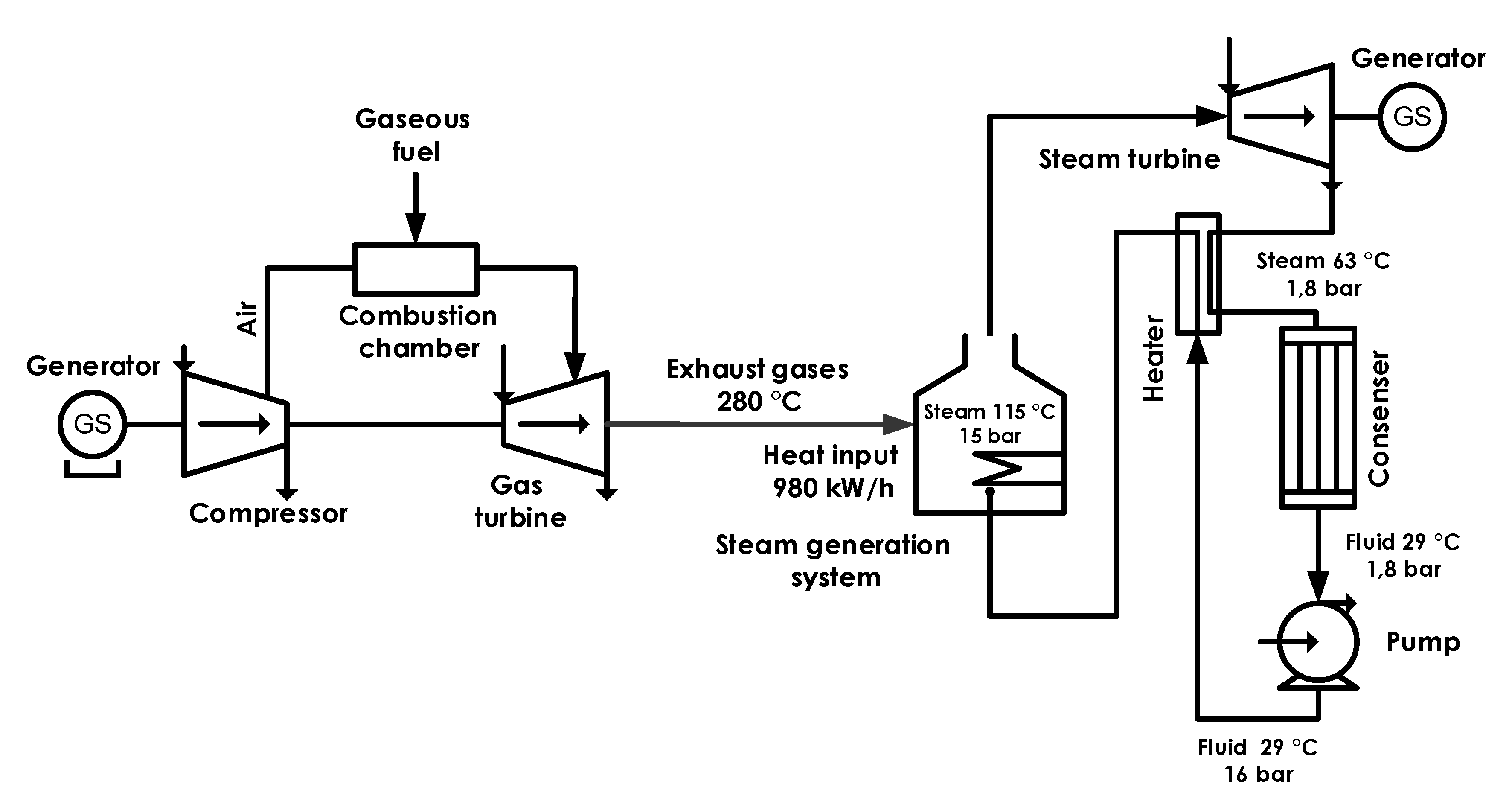
The efficiency of the steam turbine part of the installation will be defined by the work of the steam turbine itself and the pump, delivering condensed fluid from the condenser to the steam generation unit (
Figure 4).
Work of the steam turbine:
—mass steam flow, kg/s
—specific enthalpy of the fluid in n-area of the Brayton–Rankine cycle, J/kg
Summarized work of the whole turbine installation:
To assess the potential for the production of electrical power in a binary energy system, it is necessary to determine the thermal power of the GMEU exhaust gases, considering (5). As a result of research conducted at the energy facilities of several oil fields, it has been established that for gas turbines the ratio between the thermal capacity, which is later used for power generation in the binary cycle, and the electric capacity is 2:1. For gas-reciprocating units with higher electrical efficiency, this ratio can be taken as 1.5:1.
It was established that the total electrical power output of the binary power plant can be determined by the following formula:
where:
—rated electrical power of the unit;
—unit’s coefficient of technical usage;
—unit’s coefficient of load;
—coefficient of the heat energy losses in exhaust gases; –internal efficiency of steam turbine cycle.
The values of the electrical units’ load and technical usage coefficients were determined during the analysis of the energy facilities. The coefficient of the technical usage for the gas turbines was 0.79–0.84. The coefficient of the load was 0.8–0.9. The coefficient of the heat energy losses in the exhaust gases was equal to 0.95.
To calculate the potential electric power of the binary energy system it is necessary, taking into account the efficiency of the main electrical unit, to select the appropriate SMEU. The potential electric power of a binary energy system is determined as follows [
15]:
where:
—heat load of the steam generation system, W;
, —coefficients taking into account the mechanical and electrical losses in the generator, = = 0.98.
The heat load of the steam generation system can be defined as:
where:
—amount of heat contained in the exhaust gases of GMEU, W;
—temperature of GMEU exhaust gases, °C;
—temperature of exhaust gases in SMEU steam generation system, °C;
—ambient air temperature, °C.
The amount of heat contained in the exhaust gases of GMEU is found by the formula:
where
—electrical efficiency of GMEU.
GMEU Capstone C1000 was considered as the main power unit, the operating parameters of which are necessary for the selection of the auxiliary unit type, and were defined during analysis of the unit operation at an oil field of JSC “Tatneft” (
Table 2).
Considering Equations (6)–(9) we obtain the following additional possible amount of electrical energy generated in the binary energy system:
The value
was taken according to [
15].
Figure 5 shows the scheme of an energy system with a binary power generation cycle.
2.2. Integration of the GTL System into the Oil Field Structure
It is proposed to use the GTL (gas-to-liquid) system to reduce the viscosity of the pumped oils at the oilfields with a simultaneous decrease in the carbon footprint related to their production. This approach considers two-stage utilization of the associate petroleum gas. At first, APG is used as a fuel for power generation in the binary energy system. If there is unused gas after this, it is processed into synthetic liquid hydrocarbons (SLH). A study was conducted at the laboratory setup for the conversion of synthesis gas, obtained from APG, into valuable chemical products (methanol, DME and synthetic liquid hydrocarbons) [
16]. The optimal flow characteristics (volume velocity and composition of the supplied syngas) and the operating conditions of the reactors (temperature, pressure) were determined and used to simulate this process in the computer program Aspen HYSYS [
17]. Judging by the results of a chromatographic analysis for the SLH obtained at the laboratory setup, a significant proportion of the SLH are aromatic compounds (
Table 3), which have a high solubility of high molecular-weight hydrocarbons of oils.
Therefore, it should be assumed that when adding SLH to real oil systems, aromatic hydrocarbons will contribute to the destruction (dissolution) of supramolecular asphalt-resin formations and, consequently, to a change in the rheological characteristics of the oils. Such use of the GTL system will reduce the hydraulic losses during transportation, and, accordingly, the load on the pumps, as well as the required heating temperature to ensure a stable technological process.
The technological scheme of hydrocarbon production and transportation at the field with the developed GTL system is presented in
Figure 6.
The assessment of the carbon footprint of hydrocarbon production for the system developed includes an evaluation of the following stages: oil heating in fired heaters, fluid separation in the first and the second stage separators and pumping of treated oil by pumps.
The emissions of greenhouse gases generated during the burning of petroleum gas to generate electric and thermal energy for the energy supply of pumps, compressors and fired heaters are taken into account when evaluating the carbon footprint. The assessment was performed using Aspen HYSYS software for simulation of the oil production process.
3. Results and Discussion
3.1. Efficient Functioning of Developed Binary Energy System
Considering the discussion in
Section 2.1, it follows that the SMEU in the second circuit of the binary energy system should be chosen in such a way that its electrical power output is no more than 285 kW. At the same time, these two types of units have quite different operating parameters.
The main components of a gas microturbine are the compressor, combustion chamber with recuperator, turbine and generator. The compressor, turbine and generator are installed on a single shaft. The shaft of the gas turbine rotates at 96.000–116.000 rpm. As a rule, there is no rigid dependence of the generated power on the shaft rotation speed or the installation size, since the design features of individual turbines and compressors affect their size and, accordingly, the speed. For the aerodynamic design of microturbines, it is true that with a decrease in power produced, an increase in the speed of shaft rotation occurs, hence the presence of such performance characteristics. The recuperator is installed before the combustion chamber, and hot turbine exhaust gases (the temperature of which varies depending on the power of the installation) are used to heat the compressed air supplied by the compressor to the combustion chamber, which reduces the amount of fuel required to heat the fuel mixture. The gas microturbine control system includes three main operating modes—switching on and start of the operation, connecting and powering the load, and charging the battery, which is also a part of the microturbine. During the start-up of the installation, the battery allows 100% load connection. Next, the control system monitors the power parameters of consumers and the battery charge level, as well as its timely charging.
The gas microturbine generates an electric current through a generator driven by a turbo-compressor. The single-shaft high-speed generator is made with permanent magnets, and the high-frequency alternating current produced by it (with a frequency of 1600 Hz for a 30-kW installation) must be converted to a current with industrial frequency. This conversion takes place in the power electronics unit. Double conversion of the generated current is done by the rectifier and inverter in the power electronics unit, after which it is necessary to limit the higher harmonics of the current arising from this process. This unit is the most significant in a single-shaft microturbine and requires the development of a technological solution when synchronizing the operation of the installation with a network or other installations. The developed power electronics unit in a binary energy system provides synchronization of the generators’ operation in frequency, voltage level and phase angle, as well as filtering the higher harmonics of the generated current.
The main components of steam microturbine are the steam generation unit, turbine, condenser and pump. The design may be both single-shaft and two-shaft. The steam generation unit uses a low-boiling agent as a working medium to obtain standard operational parameters at lower temperatures. The condenser dissipates residual heat and collects the condensed working agent, which is then pumped back to the steam generation unit to be used again. The steam microturbine control system regulates the operation of the unit by controlling the amount of heat energy coming with the exhaust gases. A corresponding adjustment of shaft rotation speed is made to sustain the same operational parameters. Due to the fact that GMEU is the main unit in the binary energy system, the SMEU control system adjusts the voltage to match the corresponding value of the gas microturbine. This is done through the active rectifier, which allows synchronizing of the voltage levels in milliseconds.
Simulation of the developed binary energy system was done in Matlab/Simulink software. At first, the system was modeled according to Equations (1)–(5) regarding the operation of two microturbines (
Figure 7) [
18,
19].
Then a power electronics unit, consisting of the rectifier, inverter, active rectifier and higher harmonics filters was modeled [
20,
21,
22]. The simulation showed that the developed structure operated efficiently during start-up, operation, loading and unloading of the GMEU and SMEU (
Figure 8).
3.2. Lowering the Carbon Footprint of the Oil Production with the GTL System
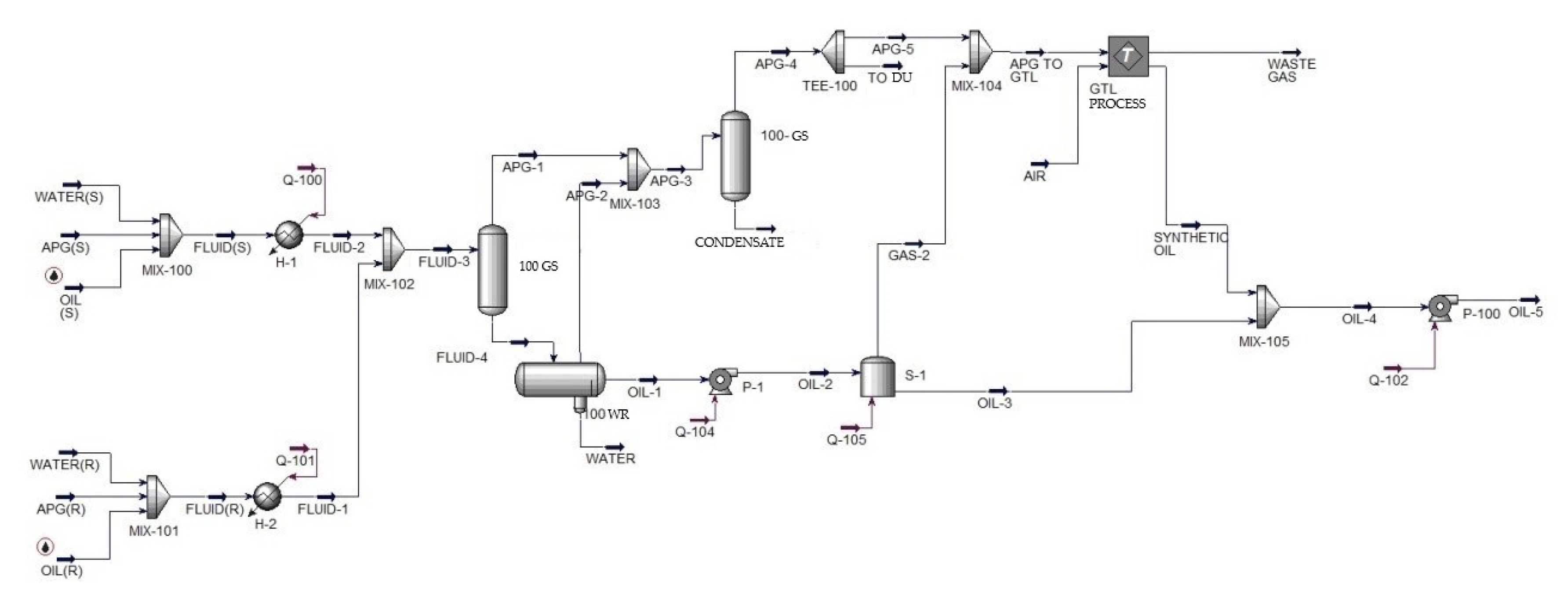
Figure 9 shows an oil field model created in the Aspen HYSYS software package. It represents an Arctic site where multiphase fluid flow (gas-oil-water) is collected from two cluster fields with high-viscosity oil and high gas-oil ratio (GOR). Next, it is heated and separated and APG is used for power production and heating of oil.
Figure 10 shows a scheme, where APG, which was burnt before, is utilized in the GTL system developed.
Comparative results of carbon footprint calculations for these two models are presented in
Figure 11.
Figure 9 illustrates burning of APG to produce heat.
Figure 10 presents additional processing of APG into synthetic oil to dilute the crude.
As a result of operating an energy system in a binary cycle, the electrical efficiency reaches 55%, i.e., it is the sum of the efficiency for the GMEU and the SMEU. At the same time, introduction of the GTL system into the APG utilization structure ensures the most complete utilization of associated petroleum gas. Power supply to consumers with electrical and/or thermal and cold energy is done according to the power load charts of the enterprise. The energy flow chart in the energy system with a binary cycle is shown in
Figure 12.
A basic economic analysis was done during the research. The economics of the proposed binary energy system was compared with a diesel power plant and a single microturbine unit in the conditions of the Arctic region. The developed structure had the highest CAPEX and the largest OPEX in the first year of operation. At the same time, the cost of diesel fuel for the diesel power plant was 200% higher due to the need to transport the diesel to the remote Arctic region by sea. This made this type of power plant economically unfeasible after two years of operation. The single microturbine unit also had lower CAPEX and OPEX in the first year of operation. However, due to the additional amount of generated energy, the constant fuel consumption binary energy system had a lesser payback period. Initial calculations showed the recoupment of the capital investments to be six years.


