Article

Mayenite Electrides and Their Doped Forms for Oxygen Reduction Reaction in Solid Oxide Fuel Cells

by
Navaratnarajah Kuganathan
1,2,*,
Ruslan V. Vovk
3 and
Alexander Chroneos
1,2
1
Department of Materials, Imperial College London, London SW7 2AZ, UK
2
Faculty of Engineering, Environment and Computing, Coventry University, Priory Street, Coventry CV1 5FB, UK
3
Physics Department, V. Karazin Kharkiv National University, Svobody Sq. 4, 61077 Kharkiv, Ukraine
*
Author to whom correspondence should be addressed.
Energies 2020, 13(18), 4978; https://doi.org/10.3390/en13184978
Submission received: 4 August 2020 / Revised: 20 September 2020 / Accepted: 22 September 2020 / Published: 22 September 2020
(This article belongs to the Special Issue Electrocatalysts for Fuel Cells and Hydrogen Production)

Abstract

:
The oxygen reduction reaction is an important reaction at the cathode in solid oxide fuel cells. Materials that exhibit high chemical and mechanical stability, high ionic and electronic conductivity, and are non-toxic are of great interest as cathodes for the reduction of oxygen. Here, we use density functional theory simulations to examine the efficacy of 12CaO·7Al2O3 and 12SrO·7Al2O3 electrides and their doped forms for the conversion of O2 gas to form O2− in their nanocages via encapsulation. Calculations show that encapsulation is exoergic in the un-doped electrides, and the formation of O2− is confirmed by the charge analysis. A stronger encapsulation is noted for C12A7 electride than the S12A7 electride. The C12A7 electride doped with B or Ga also exhibits exoergic encapsulation, but its encapsulation energy is slightly lower than that calculated for the un-doped C12A7 electride. There is an enhancement in the encapsulation for the S12A7 electride doped with B compared to its un-doped form. Doping of Ga in S12A7 electride exhibits only a very small change in the encapsulation with respect to its un-doped form. The present results can be of interest in the design of cathode material for solid oxide fuel cells.

Graphical Abstract

1. Introduction

A range of electrochemical energy storage technologies, such as batteries [1,2,3], fuel cells [4,5,6], and supercapacitors [7,8,9], has been investigated so far to cut the emission of the so-called greenhouse gases. In terms of fuel flexibility and high efficiency, solid oxide fuel cells (SOFC) are considered as promising devices to meet the global energy demand [10]. The performance of fuel cells relies on the electrode (anode and cathode) and electrolyte materials that are safe, low-cost, and efficient.
The cathode is an important component of a SOFC. The oxygen gas from the air enters into the cell through the cathode, and the oxygen reduction reaction (ORR) takes place to form O2− ions [ 1 2 O2 + 2e → O2−]. The promising cathode material is expected to have properties, such as high porosity to facilitate oxygen diffusion, chemically stable, high catalytic activity, and high electronic-ionic conductivity [11,12]. A variety of cathode materials has been studied, including ABO3 perovskite oxides (e.g., La1−xSrxMnO3) [13,14,15], oxides with the perovskite-related K2NiF4 structure (e.g., La2NiO4x) [16,17,18], and ordered double perovskites (e.g., NdBaCo2O5+x) [19,20,21,22,23].
12CaO·7Al2O3 (C12A7) is a “mayenite“ type complex nanoporous oxide mainly used as a constituent of alumina cement [24,25,26]. There are twelve nanocages per unit cell, with each cage having an inner space of ~0.4 nm. This complex oxide exhibits high chemical, thermal, and mechanical stability. Furthermore, its constituent metal oxides (CaO and Al2O3) are non-toxic and cheap. The stoichiometric form of C12A7 can be represented as C12A7:(O2−)2, in which the cation framework [Ca24Al28O64]4+ is compensated by two extra-framework O2− ions [24,25]. The electride form of C12A7 is represented as C12A7:(e)4, in which the cation framework is compensated by four extra-framework electrons. 12SrO·7Al2O3 (S12A7) [27] is isostructural with C12A7, and its stoichiometric and electride forms can be represented as S12A7:(O2−)2 and S12A7:(e)4, respectively. While both stoichiometric and electride forms of C12A7 have been well studied for different applications, only a few studies are available on the S12A7. A variety of foreign atoms, ions, and molecules has been encapsulated to tune the properties of both forms of C12A7 [28,29,30,31,32,33,34,35]. Surface structures of C12A7:(e)4 have been used as promising catalyst support to activate small molecules, such as N2 and CO2 [36,37,38].
Fast oxygen ion conductivity is one of the essential conditions for an electrolyte in SOFC and has been observed in C12A7:(O2−)2 [39,40]. Furthermore, the insulating nature of C12A7:(O2−)2 makes this material more promising for use as an electrolyte, and its oxygen ion conductivity is only one order magnitude less than that observed in yttria-stabilized zirconia [39]. The electride form of C12A7 is a candidate material for use as a cathode material in SOFC as it is electrically conductive and consists of nanocages where oxygen gas from the air can be encapsulated to form O2− (via the ORR). Additionally, the encapsulated O2− ions can diffuse fast as they do in C12A7:(O2−)2 towards electrolyte. The encapsulation capability of C12A7 and S12A7 electrides for ORR has not been explored yet. Furthermore, electrides doped with B and Ga are also worth testing to examine where there is an enhancement in the encapsulation.
In this work, we use spin-polarized density functional theory together with dispersion (DFT+D) to examine the reduction of oxygen gas to form O2− ions in the nanocages of C12A7 and S12A7 electrides and their doped forms. The current methodology allows us to calculate encapsulation energies, charges on the encapsulated O atoms, densities of states (DOSs), and charge density plots associated with the encapsulated complexes. The results to be presented here can be of interest in the development of cathode materials for SOFC.

2. Computational Methods

DFT calculations are performed to obtain energy minimized structures and electronic structures of pristine, encapsulated, and doped C12A7:(e)4 and S12A7:(e)4 using the Vienna Ab initio Simulation Program (VASP) code [41,42]. This code uses projected augmented wave (PAW) pseudopotentials [43] and plane-wave basis sets. A plane-wave basis set with the cut-off of 500 eV and a 2 × 2 × 2 Monkhorst-Pack [44] k-point mesh, which generates 8 k-points, are used in all calculations. The exchange-correlation energy is modeled using a generalized gradient approximation (GGA) scheme, as defined by Perdew, Burke, and Ernzerhof (PBE) [45]. Full geometry optimization (both atom positions and lattice constants are relaxed simultaneously) is done with the aid of the conjugate gradient algorithm [46]. In all relaxed configurations, forces on the atoms are less than 0.001 eV/Å. Dispersion forces are modeled using a semi-empirical approach, as described by Grimme et al. [47].
Encapsulation energy for a single O atom in C12A7:(e)4 with respect to ½ O2 as a reference state is calculated using the following equation:
E e n c =   E [ C 12 A 7 : O 2 ( e ) 2 ] E [ C 12 A 7 : ( e ) 4 ] E ( 1 2 O 2 )
where E [ C 12 A 7 : O 2 ( e ) 2 ] is the total energy of a single O atom encapsulated in C12A7:(e)4, E [ C 12 A 7 : ( e ) 4 ] is the total energy of bulk C12A7:(e)4, and E ( 1 2 O 2 ) is the half the energy of diatomic oxygen molecule. A similar equation is used for the encapsulation of a single oxygen atom in the doped C12A7 and S12A7 structures.

3. Results

3.1. Structures of C12A7:(e)4 and S12A7:(e)4

First, the bulk structures of C12A7:(e)4 and S12A7:(e)4 are relaxed under constant pressure. The relaxed structures are shown in Figure 1. The calculated lattice parameters, together with the experimental values, are reported in Table 1. There is a good agreement between the calculated and experimental lattice parameters of C12A7:(e)4. The S12A7:(e)4 has larger lattice parameters than C12A7:(e)4, and this is reflected in the cage pole distance of S12A7:(e)4 (refer to Figure 1c).
In our previous study [27], the electronic structure of C12A7:(e)4 has been discussed. The calculated DOS plot shows that C12A7:(e)4 is a metal (refer to Figure 2a). This is due to the extra-framework electrons occupying nanocages. A similar metallic character is noted for S12A7:(e)4 (refer to Figure 2b). Electron charge densities near the Fermi level are plotted for both C12A7:(e)4 and S12A7:(e)4. There is a uniform distribution of electrons in twelve cages of both electrides (refer to Figure 2c,d).

3.2. Encapsulation of Oxygen Atoms in C12A7:(e)4 and S12A7:(e)4

The encapsulation of two oxygen atoms is considered consequently in the empty cages of C12A7:(e)4 and S12A7:(e)4. The relaxed cages containing O2− ions are shown in Figure 3. The encapsulation results in a significant contraction in the cage pole distances. This is due to the strong attraction between Ca2+ (or Sr2+) and encapsulated O2− ions. Cage pole distances are shorter in C12A7 than that observed in S12A7. This is because of the higher charge density of Ca2+ than that of Sr2+ and shorter lattice constant of C12A7 than that of S12A7.
The calculated lattice constants and volumes of encapsulated structures are reported in Table 2. The contraction in the cage pole distances is further evidenced by the contraction in the lattice constants and volumes with respect to their electride forms. The encapsulation of two oxygen atoms leads to the stoichiometric forms of C12A7 and S12A7. The experimental lattice constants of those structures are in good agreement with the calculated values (refer to Table 2).
The encapsulation energies and the Bader charges [50] on the encapsulated oxygen atoms are reported in Table 3. The encapsulation energy calculated for the second oxygen is lower than that calculated for the first encapsulation in both cases. This is due to the less number of electrons available for the second encapsulation. The encapsulation is stronger in C12A7 than S12A7. This is because of the stronger attraction of cage pole Ca2+ ions to encapsulate O2− ions than that of Sr2+ ions. The Bader charge approximation shows that the encapsulated oxygen atom gains ~1.40 electrons from the extra-framework electrons in the cages. Notably, the Bader charge on the framework oxygen atom in the cages is ~−1.74. This is due to the strong bonding between Al3+ ions and cage wall O2− ions, resulting in short Al–O bond distances of ~1.75 Å.
The encapsulation of oxygen atoms reduces the concentration of extra-framework electrons. Once two oxygen atoms are encapsulated, all four electrons are gained by those two oxygen atoms. Figure 4a shows the DOS plot calculated for C12A7:(e)2O2−. The peak associated with the p-states of encapsulated oxygen atom appears at ~3 eV. States associated with the remaining two extra-framework electrons appear just below the Fermi level. The resultant structure is still metallic due to the remaining extra-framework electrons. In the case of C12A7:(O2−)2 (Figure 4b), the Fermi energy level shifts towards the valence band, and the system becomes an insulator. The reduction of electrons in the C12A7:(e)2O2− and the disappearance of extra-framework electrons in the C12A7:(O2−)2 are shown in Figure 4c,d, respectively. Similar DOS plots (Figure 4e,f) and the charge density plots, showing the disappearance of electrons (Figure 4g,h), are also shown.

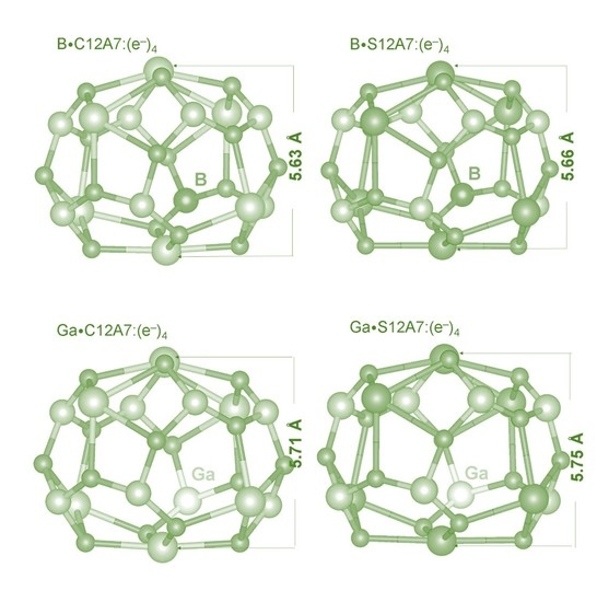
3.3. Encapsulation of Oxygen Atoms in C12A7:(e)4 and S12A7:(e)4 Doped with B and Ga

Next, the electride structures are doped with B and Ga on the Al site. Figure 5 shows the relaxed structures. Calculated lattice parameters and volumes are reported in Table 4. In the case of B-doped eletrides (refer to Figure 5a,b), cage pole distances are slightly contracted with respect to those calculated in their un-doped electrides. This is due to the strong bonding between B and the cage wall oxygen, as evidenced by the shorter B–O bond distances (1.53 Å–1.56 Å) than the Al–O bond distances (1.74 Å–1.79 Å) in the un-doped electrides. The formation of a stronger B–O bond than the Al–O bond is due to the fact that the ionization potential of B (8.2980) [51] is larger than that of Al (5.9858) [51]. The reduction in the calculated lattice parameters and volumes is further evidence for the strong B–O bond, as reported in Table 4. Doping of Ga has a very small impact on the cage pole distances, lattice parameters, and volumes with respect to the values calculated for un-doped electrides (refer to Table 1 and Table 4). However, there is a very small increase in the cage pole distances, lattice parameters, and volumes compared to those calculated in their un-doped electride forms. This is because the ionization potential of Ga (5.9993) [51] is slightly larger than that of Al (5.9858).
The calculated DOS plots for all doped configurations are shown in Figure 6. In the case of B·C12A7:(e)4, the electronic structure is slightly affected. The Fermi energy is increased only by 0.03 eV compared to the value calculated for C12A7:(e)4. The Fermi energy is unaltered upon B encapsulation in S12A7:(e)4. The resultant complexes are still metallic. Doping of Ga in C12A7:(e)4 has resulted in a small shift in the Fermi energy level by 0.06 eV. A similar effect is noted for Ga·S12A7:(e)4. Again, metallic nature is still kept. Atomic DOS plots calculated for B and Ga show that B or Ga states mainly appear in the valence band.
Finally, two oxygen atoms are encapsulated, consequently in the doped electrides. Relaxed structures of encapsulated oxygen atom-containing cages are shown in Figure 7. Table 5 reports the lattice parameters and volumes calculated in the relaxed configurations. There is an increase in the volume for oxygen encapsulated B-doped electride structures (refer to Table 5) in comparison with that calculated in the oxygen encapsulated un-doped electrides (refer to Table 2). Lattice constants are also contracted in all B-doped configurations. In the case of Ga, there is an expansion in the lattice constants and the volumes. The explanation for this difference is due to the formation of shorter B–O and longer Ga–O bonds than that of Al–O bonds (refer to Figure 7). Cage pole distances in the oxygen-containing cages are shortened upon doping of B compared to that observed in the corresponding un-doped structures. Ga-doped structures exhibit only a very small effect on the cage pole distances.
The calculated encapsulation energies and Bader charges on the B (or Ga) and the encapsulated oxygen atoms are reported in Table 6. In all configurations, B (or Ga) forms a +3 charge, as Al does. The encapsulation is exothermic in all cases, meaning that oxygen is more stable inside the cages as O2− ion than its gaseous form. Bader charge approximation confirms that the encapsulated oxygen atom gains ~1.40 electrons from the extra-framework electrons. The encapsulation energy calculated for the second oxygen atom is slightly lower than that calculated for the first oxygen atoms due to the lower number of electrons available for the second encapsulation. The encapsulation energies are more negative for C12A7 electrides than S12A7 electrides. This is due to the smaller size of the cage in C12A7 than S12A7, as evidenced by the smaller cage pole distance. In the case of B or Ga-doped C12A7 electrides, the encapsulation energies are less exothermic than that calculated for the un-doped C12A7 electrides (refer to Table 3 and Table 6). Conversely, there is a small increase in the encapsulation energies for B-doped S12A7 electride in comparison with un-doped S12A7. The encapsulation is not significantly affected by the doping of Ga in S12A7.
The calculated DOS plots for the encapsulated configurations are shown in Figure 8. The encapsulation reduces the Fermi energy (refer to Figure 6 and Figure 8). There is a significant change in the Fermi energy level between the first and the second atom encapsulation. This is because the metallic character of the first encapsulated structure disappears upon the second atom encapsulation. As both dopants (B and Ga) are isoelectronic with Al and all three atoms are in the +3 charge state, doping does not increase or decrease the concentration of electrons.

4. Conclusions

The encapsulation efficacy of C12A7 and S12A7 electrides and their doped forms are examined for the ORR at the cathode in SOFC using spin-polarized DFT simulations. The exothermic encapsulation is observed for both electrides, and the reduction of oxygen is confirmed by the negative Bader charge on the encapsulated oxygen atoms. The encapsulation is stronger in C12A7 electride than the S12A7 electride. The doped C12A7 electrides are also promising as they exhibit exoergic encapsulation, though the encapsulation is slightly lower than that calculated for the un-doped C12A7 electride. Conversely, there is an enhancement in the encapsulation for the S12A7 electride doped with B compared to its un-doped form. The Ga-doped S12A7 electride exhibits a negligible change in the encapsulation with respect to its un-doped form. The current simulation study can stimulate future experimental studies designing of cathode material for SOFC. The performance of electride materials should be tested and compared with traditional cathodes, such as lanthanum strontium manganite (LSM) and lanthanum strontium cobalt ferrite (LSCF).

Author Contributions

Computation N.K.; Writing, N.K.; Analysis and Editing, N.K., R.V.V., A.C. All authors have read and agreed to the published version of the manuscript.

Funding

This research was financially supported by the European Union’s H2020 Program under Grant Agreement no. 824072–HARVESTORE.

Acknowledgments

Coventry University and Imperial College London are acknowledged for providing computing facilities.

Conflicts of Interest

The authors declare no conflict of interest.

References

  1. Armand, M.; Tarascon, J.M. Building better batteries. Nature 2008, 451, 652. [Google Scholar] [CrossRef] [PubMed]
  2. Li, M.; Lu, J.; Chen, Z.; Amine, K. 30 Years of Lithium-Ion Batteries. Adv. Mater. 2018, 30, 1800561. [Google Scholar] [CrossRef] [PubMed] [Green Version]
  3. Winter, M.; Brodd, R.J. What Are Batteries, Fuel Cells, and Supercapacitors? Chem. Rev. 2004, 104, 4245–4270. [Google Scholar]
  4. Ormerod, R.M. Solid oxide fuel cells. Chem. Soc. Rev. 2003, 32, 17–28. [Google Scholar] [CrossRef]
  5. Stambouli, A.B.; Traversa, E. Solid oxide fuel cells (SOFCs): A review of an environmentally clean and efficient source of energy. Renew. Sustain. Energy Rev. 2002, 6, 433–455. [Google Scholar] [CrossRef]
  6. Devi, P.S.; Sharma, A.D.; Maiti, H.S. Solid Oxide Fuel Cell Materials: A Review. Trans. Indian Ceram. Soc. 2004, 63, 75–98. [Google Scholar] [CrossRef]
  7. Sharma, K.; Arora, A.; Tripathi, S.K. Review of supercapacitors: Materials and devices. J. Energy Storage 2019, 21, 801–825. [Google Scholar]
  8. Simon, P.; Gogotsi, Y.; Dunn, B. Where Do Batteries End and Supercapacitors Begin? Science 2014, 343, 1210–1211. [Google Scholar] [CrossRef] [Green Version]
  9. Muzaffar, A.; Ahamed, M.B.; Deshmukh, K.; Thirumalai, J. A review on recent advances in hybrid supercapacitors: Design, fabrication and applications. Renew. Sustain. Energy Rev. 2019, 101, 123–145. [Google Scholar] [CrossRef]
  10. Wachsman, E.D.; Marlowe, C.A.; Lee, K.T. Role of solid oxide fuel cells in a balanced energy strategy. Energy Environ. Sci. 2012, 5, 5498–5509. [Google Scholar] [CrossRef]
  11. Sun, C.; Hui, R.; Roller, J. Cathode materials for solid oxide fuel cells: A review. J. Solid State Electrochem. 2010, 14, 1125–1144. [Google Scholar] [CrossRef]
  12. Jacobson, A.J. Materials for Solid Oxide Fuel Cells. Chem. Mater. 2010, 22, 660–674. [Google Scholar] [CrossRef]
  13. Sunarso, J.; Hashim, S.S.; Zhu, N.; Zhou, W. Perovskite oxides applications in high temperature oxygen separation, solid oxide fuel cell and membrane reactor: A review. Progress in Energy and Combustion. Science 2017, 61, 57–77. [Google Scholar] [CrossRef]
  14. Tian, R.; Fan, J.; Liu, Y.; Xia, C. Low-temperature solid oxide fuel cells with La1−xSrxMnO3 as the cathodes. J. Power Sources 2008, 185, 1247–1251. [Google Scholar] [CrossRef]
  15. Gao, Z.; Mogni, L.V.; Miller, E.C.; Railsback, J.G.; Barnett, S.A. A perspective on low-temperature solid oxide fuel cells. Energy Environ. Sci. 2016, 9, 1602–1644. [Google Scholar] [CrossRef]
  16. Yang, G.; Su, C.; Ran, R.; Tade, M.O.; Shao, Z. Advanced Symmetric Solid Oxide Fuel Cell with an Infiltrated K2NiF4-Type La2NiO4 Electrode. Energy Fuels 2014, 28, 356–362. [Google Scholar] [CrossRef]
  17. Heap, R.; Islam, M.S.; Slater, P.R. Synthesis and structural characterisation of the new K2NiF4-type phases, A2In0.5Sb0.5O4 (A = Sr, Ba). Dalton Trans. 2005, 460–463. [Google Scholar] [CrossRef] [Green Version]
  18. Berry, F.J.; Moore, E.; Mortimer, M.; Ren, X.; Heap, R.; Slater, P.; Thomas, M.F. Synthesis and structural investigation of a new oxide fluoride of composition Ba2SnO2.5F3·xH2O (x≈0.5). J. Solid State Chem. 2008, 181, 2185–2190. [Google Scholar] [CrossRef]
  19. Téllez Lozano, H.; Druce, J.; Cooper, S.J.; Kilner, J.A. Double perovskite cathodes for proton-conducting ceramic fuel cells: Are they triple mixed ionic electronic conductors? Sci. Technol. Adv. Mater. 2017, 18, 977–986. [Google Scholar] [CrossRef] [Green Version]
  20. Huang, Y.-H.; Dass, R.I.; Xing, Z.-L.; Goodenough, J.B. Double Perovskites as Anode Materials for Solid-Oxide Fuel Cells. Science 2006, 312, 254–257. [Google Scholar] [CrossRef]
  21. Hu, Y.; Hernandez, O.; Broux, T.; Bahout, M.; Hermet, J.; Ottochian, A.; Ritter, C.; Genestec, G.; Dezanneau, G. Oxygen diffusion mechanism in the mixed ion-electron conductor NdBaCo2O5+x. J. Mater. Chem. 2012, 22, 18744–18747. [Google Scholar] [CrossRef]
  22. Rupasov, D.; Chroneos, A.; Parfitt, D.; Kilner, J.A.; Grimes, R.W.; Istomin, S.Y.; Antipov, E.V. Oxygen diffusion in Sr0.75Y0.25CoO2.625: A molecular dynamics study. Phys. Rev. B 2009, 79, 172102. [Google Scholar] [CrossRef] [Green Version]
  23. Parfitt, D.; Kordatos, A.; Filippatos, P.P.; Chroneos, A. Diffusion in energy materials: Governing dynamics from atomistic modelling. Appl. Phys. Rev. 2017, 4, 031305. [Google Scholar] [CrossRef]
  24. Imlach, J.A.; Dent Glasser, L.S.; Glasser, F.P. Excess oxygen and the stability of “12CaO.7A12O3”. Cem. Concr. Res. 1971, 1, 57–61. [Google Scholar] [CrossRef]
  25. Watauchi, S.; Tanaka, I.; Hayashi, K.; Hirano, M.; Hosono, H. Crystal growth of Ca12Al14O33 by the floating zone method. J. Cryst. Growth 2002, 237–239, 801–805. [Google Scholar] [CrossRef]
  26. Kim, S.W.; Matsuishi, S.; Nomura, T.; Kubota, Y.; Takata, M.; Hayashi, K.; Kamiya, T.; Hirano, M.; Hosono, H. Metallic State in a Lime−Alumina Compound with Nanoporous Structure. Nano Lett. 2007, 7, 1138–1143. [Google Scholar] [CrossRef] [PubMed]
  27. Yamaguchi, O.; Narai, A.; Shimizu, K. New Compound in the System SrO-Al2O3. J. Am. Ceram. Soc. 1986, 69, C-36. [Google Scholar] [CrossRef]
  28. Kuganathan, N.; Gkanas, E.; Chroneos, A. Encapsulation and substitution of Fe in C12A7 (12CaO⋅7Al2O3). AIP Adv. 2020, 10, 015242. [Google Scholar] [CrossRef] [Green Version]
  29. Kuganathan, N.; Chroneos, A.; Grimes, R.W. The encapsulation selectivity for anionic fission products imparted by an electride. Sci. Rep. 2019, 9, 13612. [Google Scholar] [CrossRef]
  30. Kuganathan, N.; Chroneos, A. Technetium Encapsulation by A Nanoporous Complex Oxide 12CaO•7Al2O3 (C12A7). Nanomaterials 2019, 9, 816. [Google Scholar] [CrossRef] [Green Version]
  31. Kuganathan, N.; Grimes, R.W.; Chroneos, A. Encapsulation of heavy metals by a nanoporous complex oxide 12CaO · 7Al2O3. J. Appl. Phys. 2019, 125, 165103. [Google Scholar] [CrossRef]
  32. Hayashi, F.; Tomota, Y.; Kitano, M.; Toda, Y.; Yokoyama, T.; Hosono, H. NH2− Dianion Entrapped in a Nanoporous 12CaO·7Al2O3 Crystal by Ammonothermal Treatment: Reaction Pathways, Dynamics, and Chemical Stability. J. Am. Chem. Soc. 2014, 136, 11698–11706. [Google Scholar] [CrossRef]
  33. Hayashi, K.; Hirano, M.; Hosono, H. Thermodynamics and Kinetics of Hydroxide Ion Formation in 12CaO·7Al2O3. J. Phys. Chem. B 2005, 109, 11900–11906. [Google Scholar] [CrossRef]
  34. Jeevaratnam, J.; Glasser, F.P.; Glasser, L.S.D. Anion Substitution and Structure of 12CaO·7A12O3. J. Am. Ceram. Soc. 1964, 47, 105–106. [Google Scholar] [CrossRef]
  35. Miyakawa, M.; Kamioka, H.; Hirano, M.; Kamiya, T.; Sushko, P.V.; Shluger, A.L.; Matsunami, N.; Hosono, H. Photoluminescence from Au ion-implanted nanoporous single-crystal 12CaO∙7Al2O3. Phys. Rev. B 2006, 73, 205108. [Google Scholar] [CrossRef]
  36. Toda, Y.; Hirayama, H.; Kuganathan, N.; Torrisi, A.; Sushko, P.V.; Hosono, H. Activation and splitting of carbon dioxide on the surface of an inorganic electride material. Nat. Commun. 2013, 4, 2378. [Google Scholar] [CrossRef] [PubMed] [Green Version]
  37. Kitano, M.; Kanbara, S.; Inoue, Y.; Kuganathan, N.; Sushko, P.V.; Yokoyama, T.; Hara, M.; Hosono, H. Electride support boosts nitrogen dissociation over ruthenium catalyst and shifts the bottleneck in ammonia synthesis. Nat. Commun. 2015, 6, 6731. [Google Scholar] [CrossRef] [PubMed] [Green Version]
  38. Kuganathan, N.; Hosono, H.; Shluger, A.L.; Sushko, P.V. Enhanced N2 Dissociation on Ru-Loaded Inorganic Electride. J. Am. Chem. Soc. 2014, 136, 2216–2219. [Google Scholar] [CrossRef]
  39. Lacerda, M.; Irvine, J.T.S.; Glasser, F.P.; West, A.R. High oxide ion conductivity in Ca12Al14O33. Nature 1988, 332, 525–526. [Google Scholar] [CrossRef]
  40. Hosono, H.; Hayashi, K.; Kajihara, K.; Sushko, P.V.; Shluger, A.L. Oxygen ion conduction in 12CaO·7Al2O3: O2− conduction mechanism and possibility of O− fast conduction. Solid State Ion. 2009, 180, 550–555. [Google Scholar] [CrossRef]
  41. Kresse, G.; Furthmüller, J. Efficient iterative schemes for ab initio total-energy calculations using a plane-wave basis set. Phys. Rev. B 1996, 54, 11169–11186. [Google Scholar] [CrossRef] [PubMed]
  42. Kresse, G.; Joubert, D. From ultrasoft pseudopotentials to the projector augmented-wave method. Phys. Rev. B 1999, 59, 1758–1775. [Google Scholar] [CrossRef]
  43. Blöchl, P.E. Projector augmented-wave method. Phys. Rev. B 1994, 50, 17953–17979. [Google Scholar] [CrossRef] [PubMed] [Green Version]
  44. Monkhorst, H.J.; Pack, J.D. Special points for Brillouin-zone integrations. Phys. Rev. B 1976, 13, 5188–5192. [Google Scholar] [CrossRef]
  45. Perdew, J.P.; Burke, K.; Ernzerhof, M. Generalized Gradient Approximation Made Simple. Phys. Rev. Lett. 1996, 77, 3865–3868. [Google Scholar] [CrossRef] [Green Version]
  46. Press, W.H.; Teukolsky, S.A.; Vetterling, W.T.; Flannery, B.P. Numerical Recipes in C (2nd ed.): The Art of Scientific Computing; Cambridge University Press: Cambridge, UK, 1992; p. 994. [Google Scholar]
  47. Grimme, S.; Antony, J.; Ehrlich, S.; Krieg, H. A consistent and accurate ab initio parametrization of density functional dispersion correction (DFT-D) for the 94 elements H-Pu. J. Chem. Phys. 2010, 132, 154104. [Google Scholar] [CrossRef] [Green Version]
  48. Palacios, L.; De La Torre, Á.G.; Bruque, S.; García-Muñoz, J.L.; García-Granda, S.; Sheptyakov, D.; Aranda, M.A. Crystal Structures and in-Situ Formation Study of Mayenite Electrides. Inorg. Chem. 2007, 46, 4167–4176. [Google Scholar] [CrossRef]
  49. Miyakawa, M.; Ueda, N.; Kamiya, T.; Hirano, M.; Hosono, H. Novel Room Temperature Stable Electride 12SrO•7Al2O3 Thin Films: Fabrication, Optical and Electron Transport Properties. J. Ceram. Soc. Jpn. 2007, 115, 567–570. [Google Scholar] [CrossRef] [Green Version]
  50. Bader, R.F.W. The zero-flux surface and the topological and quantum definitions of an atom in a molecule. Theor. Chem. Acc. 2001, 105, 276–283. [Google Scholar] [CrossRef]
  51. Martin, W.C. CRC Handbook of Chemistry and Physics, 86th ed.; CRC: Boca Raton, FL, USA, 2005. [Google Scholar]
Figure 1. (a,b) Relaxed structures of C12A7:(e)4 and S12A7:(e)4, respectively, and (c,d) corresponding relaxed cages occupied with extra-framework electrons. Cage pole Ca–Ca and Sr–Sr distances are calculated to be 5.70 Å and 5.73 Å in C12A7:(e)4 and S12A7:(e)4, respectively.
Energies 13 04978 g001
Figure 2. (a,b) DOS (density of states) plots calculated for C12A7:(e)4 and S12A7:(e)4, respectively, and (c,d) corresponding charge density plots associated with the extra-framework electrons.
Energies 13 04978 g002
Figure 3. Relaxed cages, containing O2− ions in the encapsulated C12A7 and S12A7 electrides. Incorporated O2− ions are shown in yellow color. (a) C12A7:(e)2O2‒, (b) C12A7:(O2−)2, (c) S12A7:(e)2O2−, (d) S12A7:(O2−)2.
Energies 13 04978 g003
Figure 4. (a,b) Calculated DOS plots of C12A7:(e)2O2− and C12A7:(O2−)2 and (c,d) corresponding charge density plots associated with remaining extra-framework electrons and encapsulated oxygen atoms, respectively. Similar plots (eh) are also shown for S12A7:(e)2O2− and S12A7:(O2−).
Energies 13 04978 g004
Figure 5. Relaxed cage structures of (a,b) B-doped and (c,d) Ga-doped electrides.
Energies 13 04978 g005
Figure 6. Calculated DOS plots for (a) B·C12A7:(e)4 and (b) B·S12A7:(e)4. Corresponding atomic DOS plots calculated for B are shown in (c) and (d), respectively. Similar DOS plots (eh) are also shown for Ga·C12A7:(e)4 and (b) Ga·S12A7:(e)4.
Energies 13 04978 g006
Figure 7. Relaxed cage structures containing encapsulated oxygen atoms in (ad) B-doped and (fi) Ga-doped electrides.
Energies 13 04978 g007
Figure 8. DOS plots for (a) B.C12A7:(e)2O2−, (b) B.C12A7:(O2−)2, (c) B.S12A7:(e)2O2−, and (d) B.S12A7:(O2−)2; Similar DOS plots (eh) are provided for oxygen encapsulated in Ga-doped electrides.
Energies 13 04978 g008
Table 1. Calculated lattice parameters of C12A7:(e)4 and S12A7:(e)4. Available experimental values are shown in parentheses.
ParametersElectrides
C12A7:(e)4S12A7:(e)4
A = b = c (Å)12.06 (12.00) [48]12.40
α = β = γ (°)90.0 90.0
V (Å3)1752.511908.59
Table 2. Calculated lattice parameters of oxygen encapsulated structures. Available experimental values are provided in parentheses.
ParametersOxygen Encapsulated Structures
C12A7:(e)2O2−S12A7:(e)2O2−C12A7:(O2−)2S12A7:(O2−)2
a (Å)12.06 12.4112.05 (11.99) [49]12.38 (12.33) [49]
b (Å)12.06 12.4112.01(11.99) [49]12.35 (12.33) [49]
c (Å)12.00 12.3612.02 (11.99) [49]12.36 (12.33) [49]
α = β = γ (°)90.090.090.0 90.0
V (Å3)1746.591902.481739.951889.90
Table 3. The encapsulation energies and Bader charge on the encapsulated oxygen atoms.
Encapsulation ProcessEncapsulation Energy (eV)Bader Charge on Encapsulated Oxygen (|e|)
C12A7:(e)4 + ½ O2 → C12A7:(e)2O2−−4.81 −1.36
C12A7:(e)2O2− + ½ O2 → C12A7:(O2−)2−4.30−1.39 (2)
S12A7:(e)4 + ½ O2 → S12A7:(e)2O2−−4.18 −1.42
S12A7:(e)2O2− + ½ O2 → S12A7:(O2−)2−4.04−1.43 (2)
Table 4. Calculated lattice parameters and volumes of doped electrides.
ParametersDoped Electrides
B·C12A7:(e)4Ga·C12A7:(e)4B·S12A7:(e)4Ga·S12A7:(e)4
a = b = c (Å)12.0212.0712.3612.42
α = β = γ (°)90.0 90.090.090.0
V (Å3)1735.691757.161890.111915.53
Table 5. Calculated lattice parameters and volumes of oxygen encapsulated doped structures.
ParametersOxygen Encapsulated Doped Structures
B·C12A7:(e)2O2−B·S12A7:(e)2O2−B·C12A7:(O2−)2B·S12A7:(O2−)2
a (Å)12.0212.3611.9812.32
b (Å)12.0212.3611.9812.32
c (Å)11.9712.3311.9712.32
α = β = γ (°)90.090.090.090.0
V (Å3)1730.131883.531719.301870.62
Ga·C12A7:(e)2O2−Ga·S12A7:(e)2O2−G·C12A7:(O2−)2Ga·S12A7:(O2−)2
a (Å)12.0812.4212.0712.40
b (Å)12.0712.4112.0212.36
c (Å)12.0212.3712.0312.38
α = β = γ (°)90.090.090.090.0
V (Å3)1751.071907.551744.471896.43
Table 6. The encapsulation energies and Bader charge on the encapsulated oxygen atoms in doped structures.
Encapsulation ProcessEncapsulation Energy (eV)Bader Charge (|e|)
B or Ga O
B·C12A7:(e)4 + ½ O2 → B·C12A7:(e)2O2−−4.72+3.00−1.39
B·C12A7:(e)2O2− + ½ O2 → B·C12A7:(O2−)2−4.62+3.00−1.40, −1.44
Ga·C12A7:(e)4 + ½ O2 → Ga·C12A7:(e)2O2−−4.56+3.00−1.37
Ga·C12A7:(e)2O2− + ½ O2 → Ga·C12A7:(O2−)2−4.25+3.00−1.38, −1.40
B·S12A7:(e)4 + ½ O2 → B·S12A7:(e)2O2−−4.31+3.00−1.42
B·S12A7:(e)2O2− + ½ O2 → B·S12A7:(O2−)2−4.29+3.00−1.43 (2)
Ga·S12A7:(e)4 + ½ O2 → Ga·S12A7:(e)2O2−−4.17+3.00−1.40
Ga·S12A7:(e)2O2− + ½ O2 → Ga·S12A7:(O2−)2−3.94+3.00−1.43 (2)

