Study on Line-Start Permanent Magnet Assistance Synchronous Reluctance Motor for Improving Efficiency and Power Factor
Abstract
1. Introduction
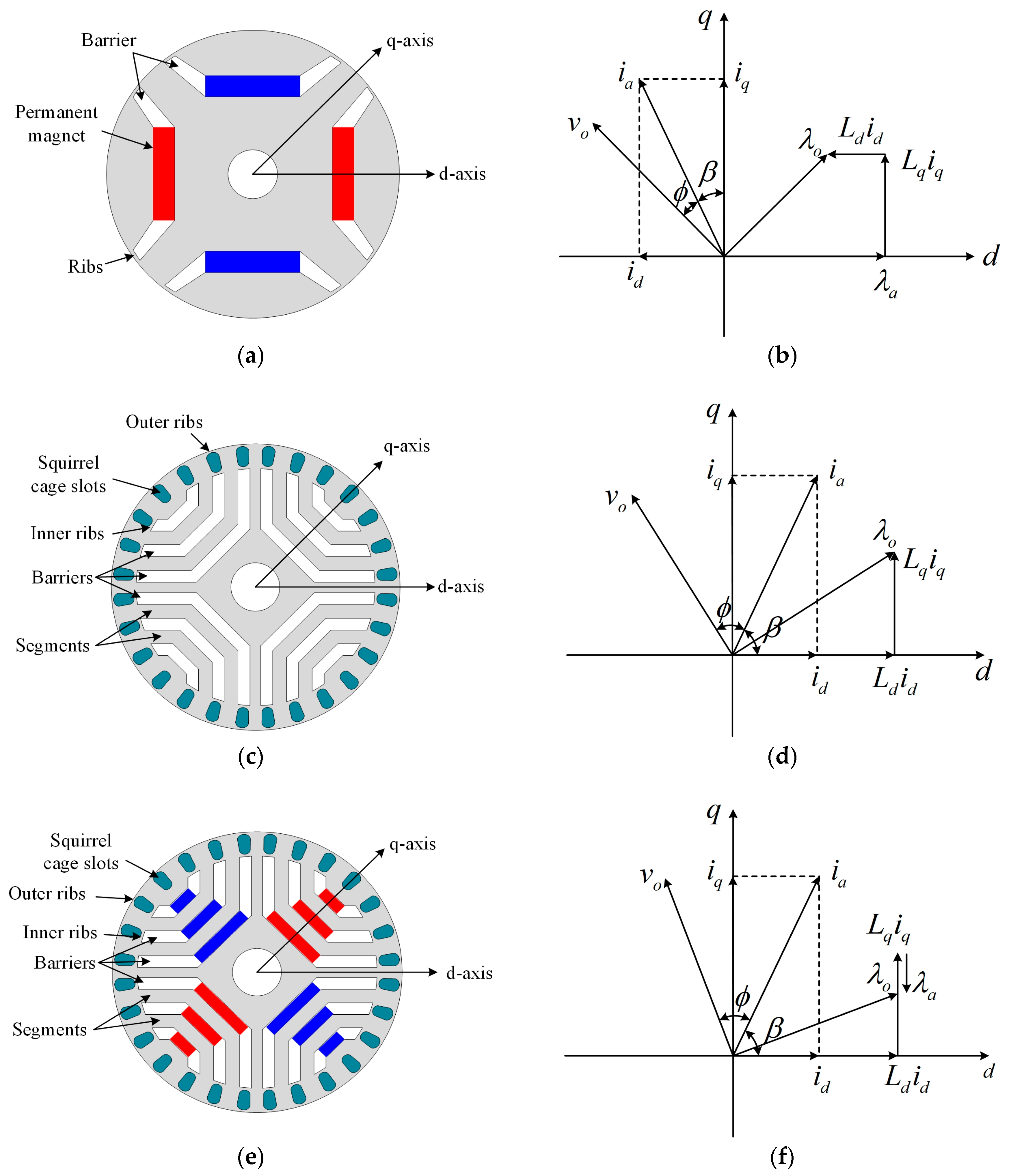
2. Characteristics of LS-SynRM and LS-PMA-SynRM
2.1. Asynchronous Operation
2.2. Synchronous Operation
2.2.1. Efficiency
2.2.2. Power Factor
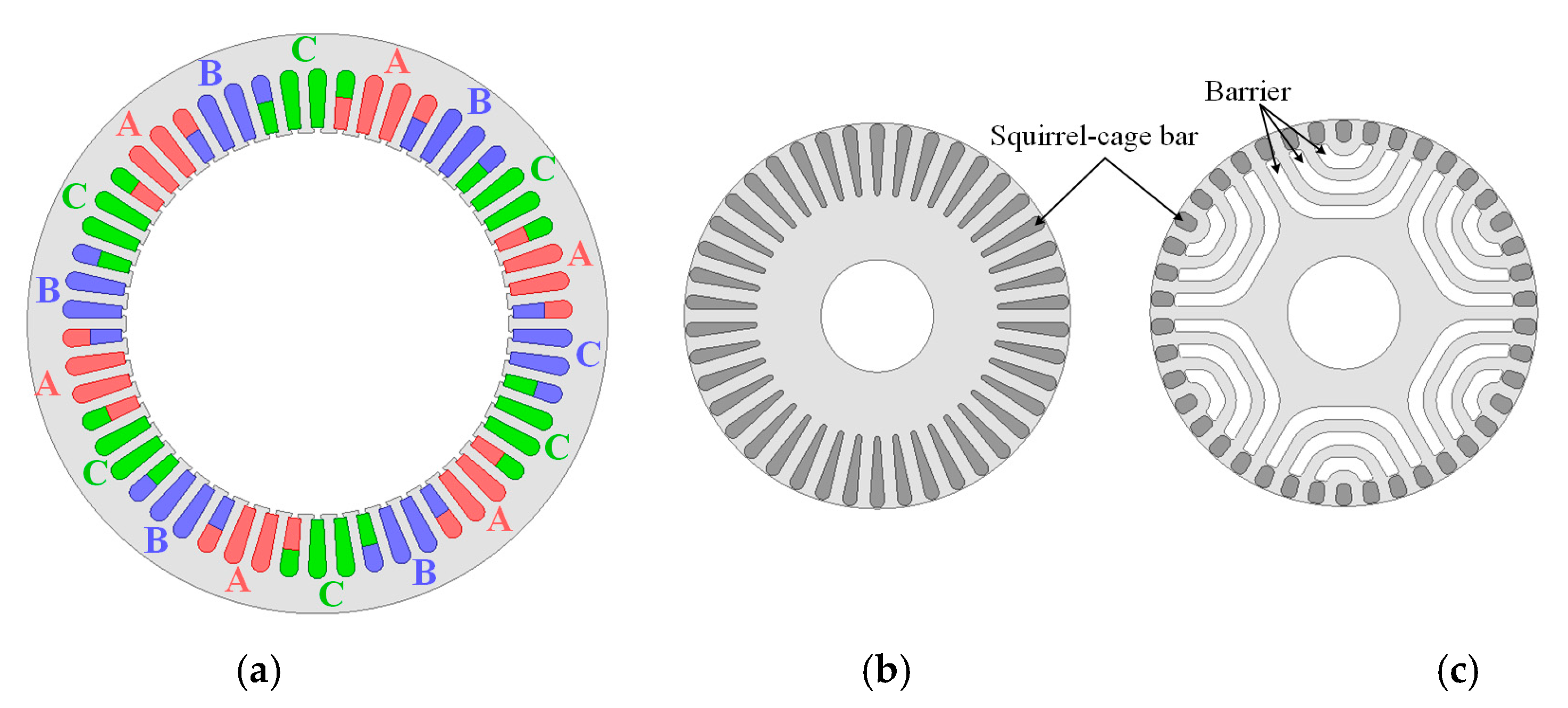
3. FEA Models of Reference Models
3.1. Specification of Reference Models
3.2. Material for FEA
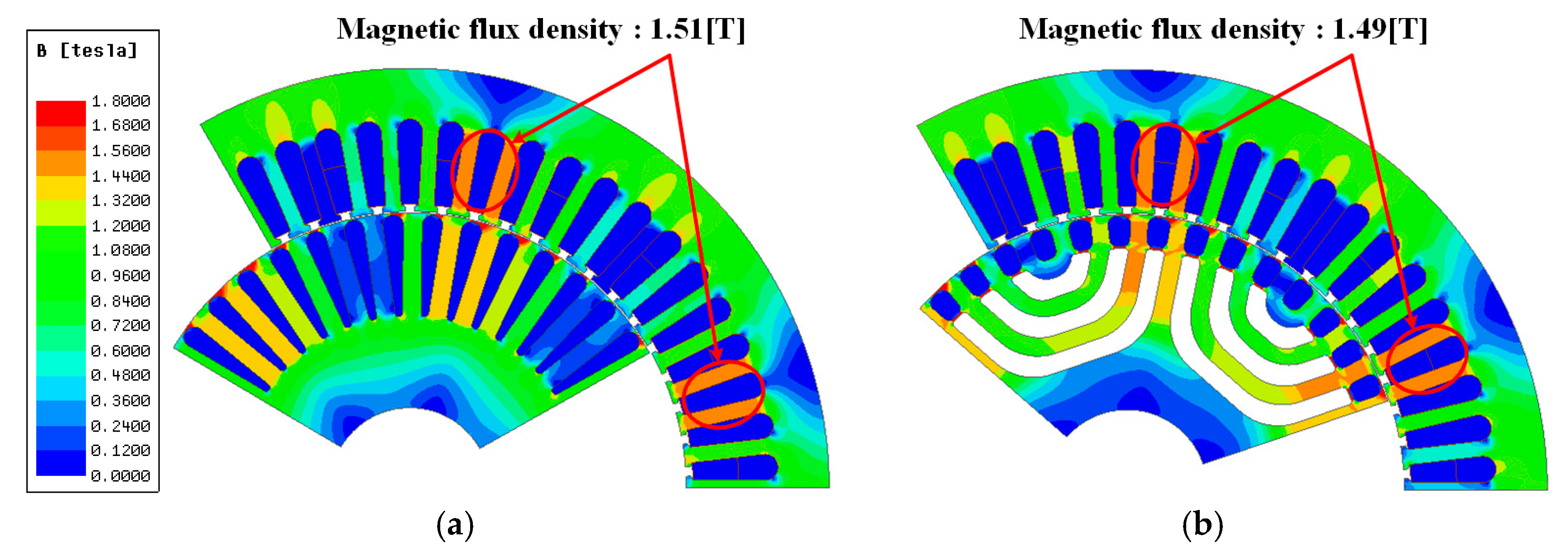
3.3. FEA Result
4. Design of LS-PMA-SynRM
4.1. Position of Magnet
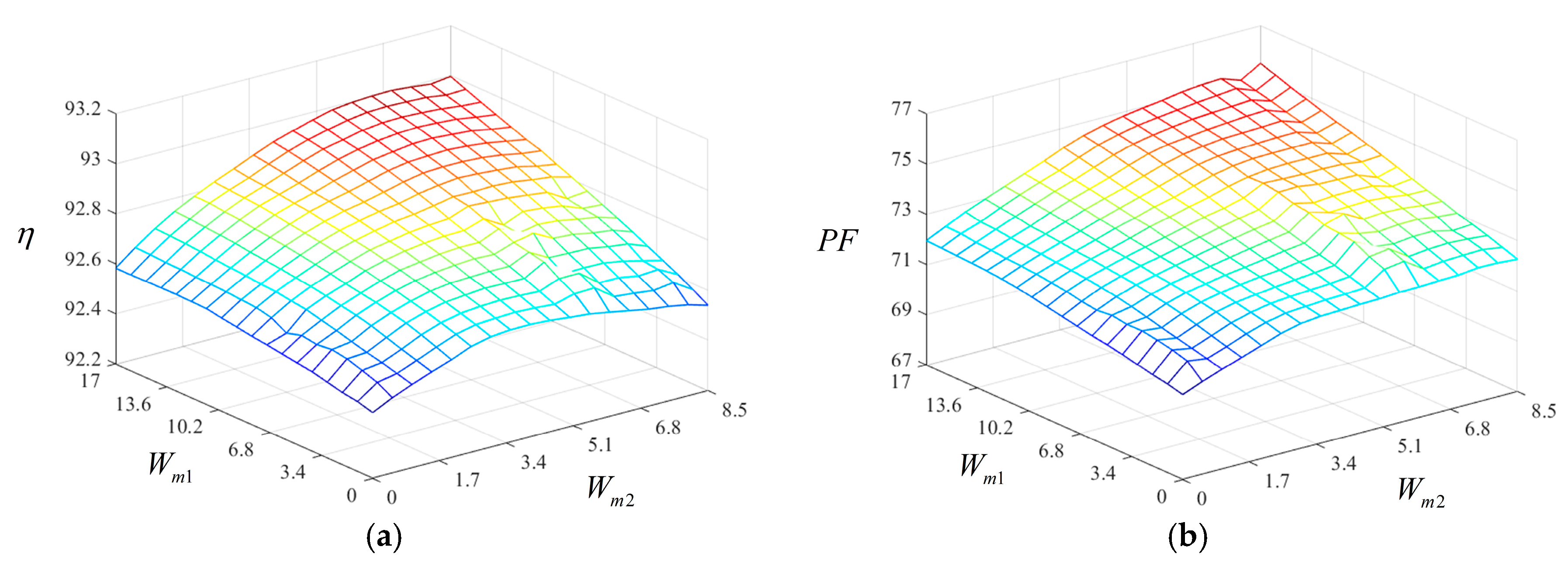
4.2. Length of Magnet
4.3. Final Model of LS-PMA-SynRM
5. Verification
5.1. Manufacture
5.2. Experiment Result
5.3. Discussion
6. Conclusions
Author Contributions
Funding
Conflicts of Interest
References
- Kersten, A.; Liu, Y.; Pehrman, D.; Thiringer, T. Rotor Design of Line-Start Synchronous Reluctance Machine with Round Bars. IEEE Ind. Appl. 2019, 55, 3685–3696. [Google Scholar] [CrossRef]
- Almeida, A.T.D.; Ferreira, F.J.T.E.; Baoming, G. Beyond Induction Motors-Technology Trends to Move Up Efficiency. IEEE Ind. Appl. 2014, 50, 2103–2114. [Google Scholar] [CrossRef]
- Almeida, A.T.D.; Ferreira, F.J.T.E.; Fong, J.A.C. Standards for Efficiency of Electric Motor. IEEE Ind. Appl. Mag. 2011, 17, 12–19. [Google Scholar] [CrossRef]
- Matko, V.; Brezovec, B. Improved Data Center Energy Efficiency and Availability with Multilayer Node Event Processign. Energies 2018, 11, 2478. [Google Scholar] [CrossRef]
- Jia, M.; Srinivasan, R.S.; Raheem, A.A. From occupancy to occupant behavior: An analytical survey of data acquisition technology, modeling methodologies and simulation coupling mechanisms for building energy efficiency. Renew. Sustan. Energy Rev. 2017, 68, 525–540. [Google Scholar] [CrossRef]
- Ferreira, F.J.T.E.; Baoming, G.; Almeida, A.T.D. Reliability and Operation of High-Efficiency Induction Motors. IEEE Ind. Appl. 2016, 52, 4628–4637. [Google Scholar] [CrossRef]
- Xie, Y.; Pi, C.; Li, Z. Study on Design and Vibration Reduction Optimization of High Starting Torque Induction Motor. Energies 2019, 12, 1263. [Google Scholar] [CrossRef]
- Rafajdus, P.; Hrabovcova, V.; Lehocky, P.; Makys, P.; Holub, F. Effect of Saturation on Field Oriented Control of the New Designed Reluctance Synchronous Motor. Energies 2018, 11, 3223. [Google Scholar] [CrossRef]
- Aguba, V.; Muteba, M.; Nicolae, D.V. Transient Analysis of a Start-up Synchronous Reluctance Motor with Symmetrical Distributed Rotor Cage Bars. In Proceedings of the 2017 IEEE AFRICON, Cape Town, South Africa, 18–20 September 2017. [Google Scholar]
- Liu, H.C.; Lee, J. Optimum Design of an IE4 Line-Start Synchronous Reluctance Motor Considering Manufacturing Process Loss. IEEE Trans. Ind. Electron. 2018, 65, 3104–3114. [Google Scholar] [CrossRef]
- Lee, J.K.; Jung, D.H.; Lim, J.; Lee, K.D.; Lee, J. A Study on the Synchronous Reluctance Motor Design for High Torque by Using RSM. IEEE Trans. Magn. 2018, 54, 8103005. [Google Scholar] [CrossRef]
- Ozcelik, N.G.; Dogru, U.E.; Imeryuz, M.; Ergene, L.T. Synchronous Reluctance Motor vs. Induction Motor at Low-Power Industrial Applications: Design and Comparison. Energies 2019, 12, 2190. [Google Scholar] [CrossRef]
- Tampio, J.; Kansakangas, T.; Suuriniemi, S.; Kolehmainen, J.; Kettunen, L.; Ikaheimo, J. Analysis of Direct-On-Line Synchronous Reluctance Machine Start-Up Using a Magnetic Field Decomposition. IEEE Trans. Ind. Appl. 2017, 53, 1852–1859. [Google Scholar] [CrossRef]
- Boroujeni, S.T.; Bianchi, N.; Alberti, L. Fast Estimation of Line-Start Reluctance Machine Parameters by Finite Element Analysis. IEEE Trans. Energy Convers. 2011, 26, 1–8. [Google Scholar] [CrossRef]
- Liu, H.C.; Hong, H.S.; Cho, S.; Lee, J.; Jin, C.S. Bubbles and Blisters Impact on Diecasting Cage to the Designs and Operations of Line-Start Synchronous Reluctance Motors. IEEE Trans. Magn. 2017, 53, 8202504. [Google Scholar] [CrossRef]
- Zhao, W.; Xing, F.; Wang, X.; Lipo, T.A.; Kwon, B.-I. Design and Analysis of a Novel PM-Assisted Synchronous Reluctance Machine with Axially Integrated Magnets by the Finite-Element Mehtod. IEEE Trans. Magn. 2017, 53, 8104104. [Google Scholar] [CrossRef]
- Joo, K.-J.; Kim, I.-G.; Lee, J.; Go, S.-C. Robust Speed Sensorless Control to Estimated Error for PMa-SynRM. IEEE Trans. Magn. 2017, 53, 8102604. [Google Scholar] [CrossRef]
- Kim, W.-H.; Kim, K.-S.; Kim, S.-J.; Kang, D.-W.; Go, S.-C.; Chun, Y.-D.; Lee, J. Optimal PM Design of PMA-SynRM for Wide Constant-Power Operation and Torque Ripple Reduction. IEEE Trans. Magn. 2009, 45, 4660–4663. [Google Scholar] [CrossRef]
- Almeida, A.T.D.; Ferrera, F.J.T.E.; Duarte, A.Q. Technical and Economcal Considerations on Super High-Efficiency Three-Phase Motors. IEEE Trans. Ind. Appl. 2014, 50, 1274–1285. [Google Scholar] [CrossRef]
- Kong, Y.; Lin, M.; Yin, M.; Hau, L. Rotor Structure on Reducing Demagnetization of Magnet and Torque Ripple in a PMa-synRM With Ferrite Permanent Magnet. IEEE Trans. Magn. 2018, 54, 8108705. [Google Scholar] [CrossRef]
- Mingardi, D.; Bianchi, N. Line-Start PM-Assisted Synchronous Motor Design, Optimization, and Tests. IEEE Trans. Ind. Electron. 2017, 64, 9739–9747. [Google Scholar] [CrossRef]
- Jung, D.-H.; Kwak, Y.; Lee, J.; Jin, C.-S. Study on the Optimal Design of PMa-SynRM Loading Ratio for Achievement of Ultrapremium Eifficieny. IEEE Trans. Magn. 2017, 53, 8001904. [Google Scholar] [CrossRef]
- Liu, H.-C.; Joo, K.-J.; Oh, Y.J.; Lee, H.-J.; Seol, H.-S.; Jin, C.-S.; Kim, W.-H.; Lee, J. Optimal Design of an Ultra-Premium-Eifficiency PMA-Synchronous Reluctance Motor with the Winding Method and Stator Parameters to Reduce Flu Leakage and Minimize Torque Pulsations. IEEE Trans. Magn. 2018, 54, 8207505. [Google Scholar] [CrossRef]
- Wang, X.; Zhu, C.; Zhang, R.; Tang, R.; Song-Yop, H. Performance Analysis of Single-Phase Induction Motor Based on Voltage Source Complex Finite-Element Analysis. IEEE Trans. Magn. 2006, 42, 587–590. [Google Scholar] [CrossRef]
- Lee, S.-H.; Kwon, S.; Lee, J.-J.; Hong, J.-P. Characteristic Analysis of Claw-Pole Machine Using Improved Equivalent Magnetic Circuit. IEEE Trans. Magn. 2009, 45, 4570–4573. [Google Scholar]
- Shimotani, T.; Sato, T.; Igarashi, H. Fast Finite-Element Analysis of Motors Using Block Model Order Reduction. IEEE Trans. Magn. 2016, 52, 7207004. [Google Scholar] [CrossRef]
- Lee, J.-J.; Lee, J.; Kim, K.-S. Design of a WFSM for an Electric Vehicle Based on a Nonlinear Magnetic Equivalent Circuit. IEEE Trans. Appl. Supercond. 2018, 28, 5206304. [Google Scholar] [CrossRef]
- Lin, I.-H.; Hsieh, M.-F.; Kuo, H.-F.; Tsai, M.-C. Improved Accuracy for Performance Evaluation of Synchronous Reluctance Motor. IEEE Trans. Magn. 2015, 51, 8113404. [Google Scholar] [CrossRef]
- Lee, B.-H.; Hong, J.-P.; Lee, J.-H. Optimum Design Criteria for Maximum Torque and Efficiency of a Line-Start Permanent-Magnet Motor Using Response Surface Methodology and Finite Element Method. IEEE Trans. Magn. 2012, 48, 863–866. [Google Scholar] [CrossRef]
- Li, N.; Zhu, J.; Lin, M.; Yang, G.; Kong, Y.; Hau, L. Analysis of Axial Field Flux-Switching Memory Machines Based on 3-D Magnetic Equivalent Circuit Network Considering Magnetic Hysteresis. IEEE Trans. Magn. 2019, 55, 7203104. [Google Scholar] [CrossRef]
- Zhang, Y.; Chau, K.T.; Zhang, D.; Liu, C. A Finite Element-Analytical Method for Electromagnetic Field Analysis of Electric Machines with Free Rotation. IEEE Trans. Magn. 2006, 42, 3392–3394. [Google Scholar] [CrossRef]
- Sadiku, M.N.O. A Simple Introduction to Finite Element Analysis of Electromagnetic Problems. IEEE Trans. Magn. 1989, 32, 85–93. [Google Scholar] [CrossRef]
- Liu, H.C.; Seol, H.S.; Kim, J.Y.; Lee, J. Design and Analysis of an IE4 Class Line-Start Synchronous Reluctance Motor Considering Total Loss and Starting Performance. J. Electron. Mater. 2019, 48, 1386–1394. [Google Scholar] [CrossRef]




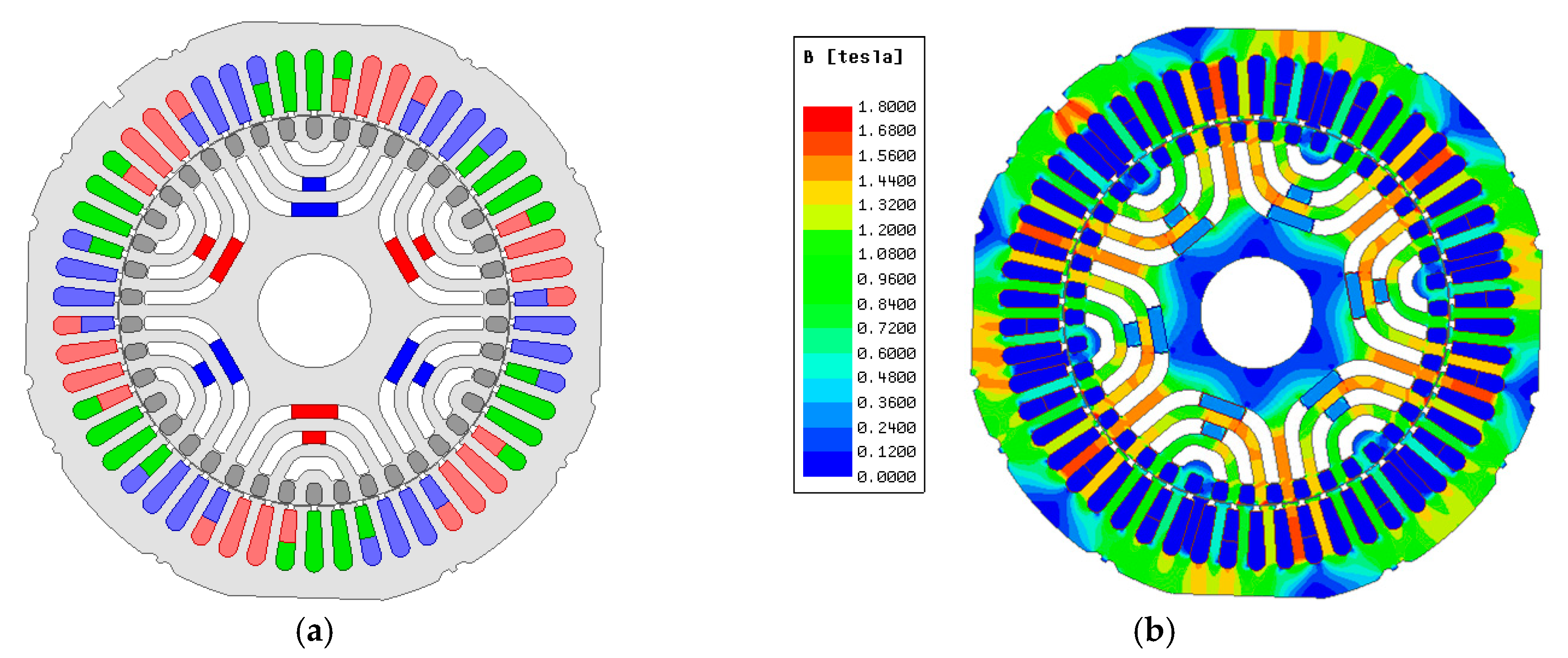

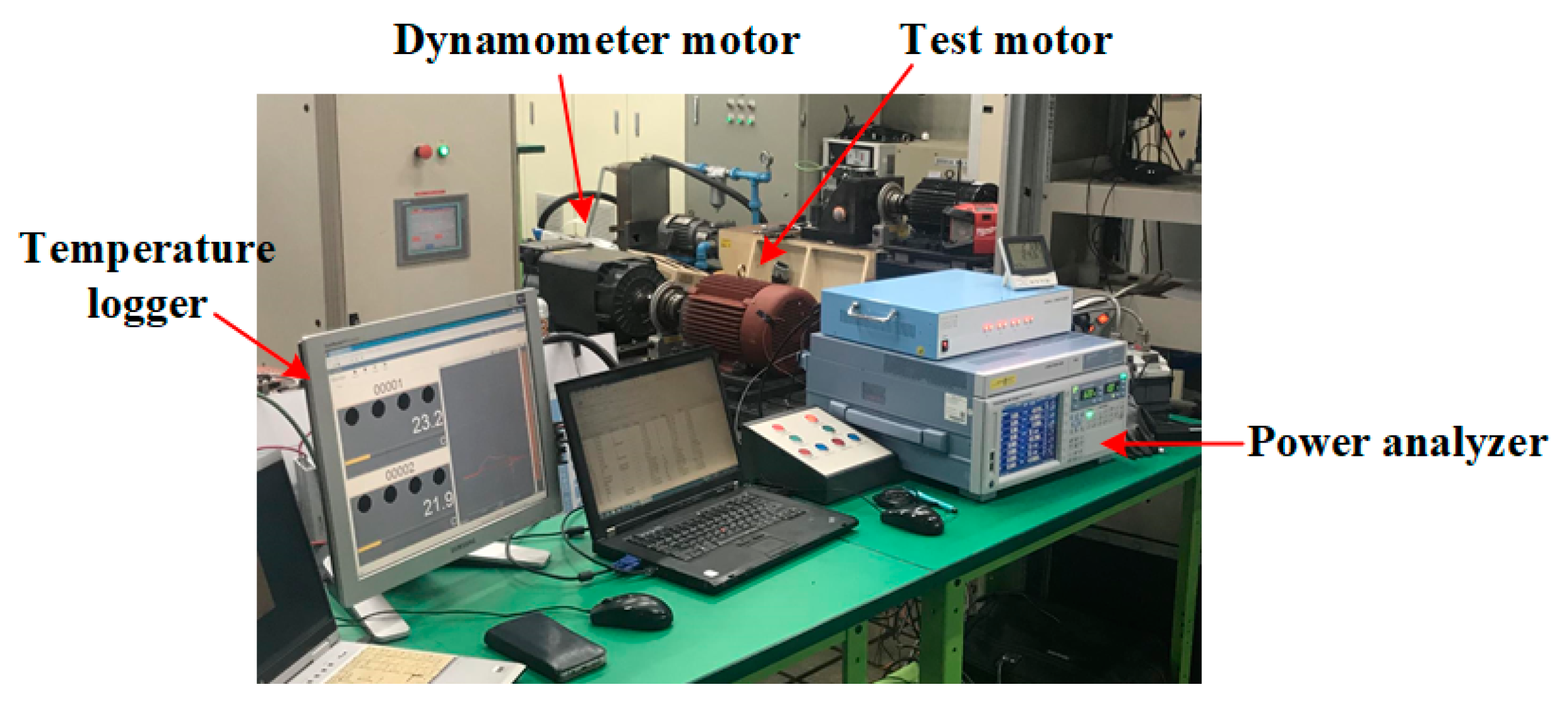

| Item | Value | Unit | |
|---|---|---|---|
| Rated | Output Power | 5.5 | kW |
| Input voltage | 380 | V | |
| Input frequency | 60 | Hz | |
| Stator | Number of slots | 54 | – |
| Stator outer diameter | 220 | mm | |
| Stator inner diameter | 145 | mm | |
| Rotor | Number of slots | 42 | – |
| Rotor outer diameter | 144.2 | mm | |
| Rotor inner diameter | 42 | mm | |
| Number of poles | 6 | – | |
| Stack length | 170 | mm | |
| Airgap length | 0.3 | mm | |
| Rib length | 0.4 | mm | |
| Item | Material | Conductivity | Unit |
|---|---|---|---|
| Stator | 50PN470 (S18) | 2.38 106 | S/m |
| Rotor | |||
| Winding | Copper | 5.8 107 | S/m |
| Squirrel-cage bar | Aluminum | 3.6 107 | S/m |
| Item | Value | Unit | |
|---|---|---|---|
| IM | LS-SynRM | ||
| Power | 5.5 | 5.5 | kW |
| Speed | 1170.8 | 1200 | rpm |
| Torque | 48.1 | 45.5 | Nm |
| Current | 11.55 | 12.88 | A |
| Core loss | 94.36 | 90.12 | W |
| Stator copper loss | 214.35 | 266.69 | W |
| Rotor copper loss | 143.8 | 25.39 | W |
| Total loss | 452.55 | 382.21 | W |
| Efficiency | 91.46 | 92.46 | % |
| Power factor | 80.14 | 70.39 | – |
| Item | Value | Unit |
|---|---|---|
| Residual flux density | 0.39 | T |
| Coercive force | 3.703 | kOe |
| Item | Value | Unit |
|---|---|---|
| Power | 5.5 | kW |
| Speed | 1200 | rpm |
| Torque | 44 | Nm |
| Current | 11.98 | A |
| Core loss | 93.79 | W |
| Stator copper loss | 229.04 | W |
| Rotor copper loss | 24.84 | W |
| Total loss | 347.68 | W |
| Efficiency | 93 | % |
| Power factor | 75.5 | – |
| Item | Value | Unit | |
|---|---|---|---|
| IM | LS-PMA-SynRM | ||
| Power | 5.5 | 5.5 | kW |
| Speed | 1175 | 1200 | rpm |
| Torque | 44.7 | 43.7 | Nm |
| Current | 12.3 | 12.6 | A |
| Core loss | 106 | 105.9 | W |
| Stator copper loss | 249.5 | 257.7 | W |
| Rotor copper loss | 124.6 | 0 | W |
| Total loss | 535.3 | 433.75 | W |
| Efficiency | 91.13 | 92.69 | % |
| Power factor | 74.5 | 71.2 | – |
© 2020 by the authors. Licensee MDPI, Basel, Switzerland. This article is an open access article distributed under the terms and conditions of the Creative Commons Attribution (CC BY) license (http://creativecommons.org/licenses/by/4.0/).
Share and Cite
Kim, H.; Park, Y.; Liu, H.-C.; Han, P.-W.; Lee, J. Study on Line-Start Permanent Magnet Assistance Synchronous Reluctance Motor for Improving Efficiency and Power Factor. Energies 2020, 13, 384. https://doi.org/10.3390/en13020384
Kim H, Park Y, Liu H-C, Han P-W, Lee J. Study on Line-Start Permanent Magnet Assistance Synchronous Reluctance Motor for Improving Efficiency and Power Factor. Energies. 2020; 13(2):384. https://doi.org/10.3390/en13020384
Chicago/Turabian StyleKim, Hyunwoo, Yeji Park, Huai-Cong Liu, Pil-Wan Han, and Ju Lee. 2020. "Study on Line-Start Permanent Magnet Assistance Synchronous Reluctance Motor for Improving Efficiency and Power Factor" Energies 13, no. 2: 384. https://doi.org/10.3390/en13020384
APA StyleKim, H., Park, Y., Liu, H.-C., Han, P.-W., & Lee, J. (2020). Study on Line-Start Permanent Magnet Assistance Synchronous Reluctance Motor for Improving Efficiency and Power Factor. Energies, 13(2), 384. https://doi.org/10.3390/en13020384


