Article

CFD Analysis on the Balancing Hole Design for Magnetic Drive Centrifugal Pumps

1
Department of Mechanical & Vehicle Engineering, Kangwon National University, 346, Jungang-ro, Samcheok-si, Gangwon-do 25913, Korea
2
School of Mechanical System Engineering, Kangwon National University, 346, Jungang-ro, Samcheok-si, Gangwon-do 25913, Korea
*
Author to whom correspondence should be addressed.
Energies 2020, 13(22), 5865; https://doi.org/10.3390/en13225865
Submission received: 9 October 2020 / Revised: 7 November 2020 / Accepted: 9 November 2020 / Published: 10 November 2020
(This article belongs to the Section I: Energy Fundamentals and Conversion)

Abstract

:
Balancing holes in single-suction centrifugal pumps are generally applied to attenuate the axial thrust caused by a pressure difference between the front side of a shroud and the rear side of a hub of an impeller. The magnetic drive pump, the subject of this study, has a leak-free airtight structure and an integrated structure of the impeller and inner magnet. To prevent the performance degradation of the magnetic drive caused by heat during operation, complex cooling flow paths connected to balancing holes have been designed so that a sufficient amount of coolant would flow around the magnetic drive. Due to this spatial characteristic, when balancing holes are applied to a magnetic drive pump, the balancing hole flow path becomes very long compared to that of balancing holes applied to conventional pumps. When the balancing hole flow path is long, the flow path loss increases, which in turn increases the adverse effect of balancing holes on the pump performance. Therefore, the design of highly efficient balancing holes to which a sufficient amount of coolant can be supplied is critical in a magnetic drive pump. To this end, two types of balancing holes were investigated in this study. First, balancing holes are drilled in the impeller that rotates during operation. Second, balancing holes are drilled in the inner shaft installed to maintain the centre of rotation of the impeller during pump operation. The results confirmed the flow characteristics of the two types of balancing holes and verified the effect of each balancing hole on the pump performance. Finally, this study found that drilling balancing holes in the shaft were appropriate for the magnetic drive pump, and this type can maintain relatively high efficiency and supply a sufficient amount of coolant to maintain the efficiency of the magnetic drive.

1. Introduction

The advancement of industries has led to the development of the uses of pumps. However, the working fluids of pumps used in petrochemical, semiconductor, food, and wastewater treatment industries are highly corrosive or toxic and can cause dangerous situations if leaked during operation due to incomplete sealing. Therefore, the demand for magnetic drive pumps that have a leak-free structure and can perfectly seal the working fluid is continuously increasing. The magnetic drive pump requires a sealed structure that does not leak during operation. Moreover, unlike the conventional centrifugal pumps, the magnetic drive pump has a complex internal structure, such as an inner magnet for driving the impeller and a cooling flow path to remove heat generated from the magnet during operation. Furthermore, axial thrust is generated in the magnetic drive pump by a pressure difference between the front shroud side and rear hub side of the impeller, similar to the conventional centrifugal pumps. In general, excessive axial thrust can be a direct cause of bearing damage and pump performance loss; thus, various methods have been used to reduce the axial thrust. Representative methods are balancing holes, back vane, and balance disk. Among these methods, balancing holes are the most widely used in general centrifugal pumps. Not many studies related to the axial thrust of magnetic drive pumps have been published so far, and there are even fewer studies related to balancing holes. However, many studies on the reduction of the axial thrust of general centrifugal pumps have been reported. Pehlivan et al. [1] examined the effects of physical properties, such as the back gap of the impeller, wear ring, and balancing holes on the axial thrust. The results showed that the wear ring and balancing holes influenced the axial thrust, but the back gap of the impeller did not have a significant influence on the axial thrust. Lefor et al. [2] compared the casing ribs and J-grooves used to lower the bearing weight of a centrifugal pump. They focused on the improvement of J-grooves and found that the efficiency of J-grooves increased by 1.14%. Cao, Dai, and Hu [3] examined the effects of the size of impeller reflux balancing holes for centrifugal pumps on the pressure distribution of the front and rear shrouds and rear pump chamber and on the energy characteristics of the entire pump and axial thrust. The results showed that the axial thrusts of pumps with reflux balancing holes of 5.2 and 5.9 mm diameters were significantly lower than that of a pump with a reflux balancing hole of 4.5 mm diameter. The axial thrust balance improved when the ratio of the area between the reflux balancing hole and the sealing ring was higher than six. Babayigit et al. [4] investigated differences in the performance of a two-stage centrifugal pump with and without balancing holes. As a result, an efficiency difference of 12.9% occurred depending on the existence and absence of balancing holes at a flow rate of 55 m3/h and an efficiency difference of 13.4% at a flow rate of 80 m3/h. Fanyu et al. [5] suggested a design using a cooling system to offset the axial thrust and a calculation process of the axial thrust using a formula. Hong and Kang [6] reported that when balancing holes were installed, the pressure on the front and rear sides of the casing and the pump performance decreased, and the axial thrust significantly decreased compared to the opposite case. Lee et al. [7] found that the larger the diameter of balancing holes applied to the centrifugal pump, the higher the leaked flow rate. This condition decreased the head and efficiency, but it could also effectively reduce the axial thrust. Kim et al. [8] proposed a method of installing a vane in the pump casing in addition to the existing axial thrust control design to control the pressure of the cavity at the back of the impeller. When the axial thrust of the pump was measured by attaching three kinds of vanes to the rear of the impeller of a high-speed centrifugal pump manufactured for liquid rocket engines, the shape of the vane did not have a significant effect on the pump head. Furthermore, the larger the vane, the higher the axial thrust, and the direction of the axial thrust was changed when there was no vane. Choi et al. [9] reported that applying J-grooves for controlling the size of the axial thrust by making a number of radial grooves on the wall of the casing could significantly reduce the working fluid rotation speed inside the casing. Moreover, this method could significantly reduce the axial thrust by making the pressure distribution in the gap behind the impeller almost flat.
The present study conducted computational fluid dynamics (CFD) analysis on two different types of balancing holes that can be commercialized to investigate the phenomena of the flow of working fluid in flow paths inside a pump, including the cooling flow path in the design of balancing holes. These factors need to be considered in the development process of a magnetic drive pump. In this process, the effects of different structures and diameters of balancing holes on the flow rate through the complex cooling flow path and on the pump performance and axial thrust were examined through a CFD analysis using the commercial program Ansys CFX.
Table 1 shows the operational specifications at the design points of a 15 HP magnetic drive pump, which is the subject of this study [6,10,11].

2. Numerical Analysis

2.1. Flow Path Structure in the Magnetic Drive Pump and Analysis Models for the Two Types of Balancing Holes

Figure 1 is a two-dimensional (2D) cross-section showing the coolant flow path and internal structure of the magnetic drive pump. In this figure, the water entering the inlet at the left of the impeller must exit through the outlet after flowing through the blades and volute. However, in actuality, not all the water entering the impeller exits through the outlet, and some of the water flows to the front and rear flow paths, instead of the volute, resulting in leakage. Furthermore, the magnetic drive pump in Figure 1 is designed as an integrated structure with an inner magnet in the impeller. The purpose of this design is to completely seal the working fluid, which can be harmful, inside the pump and to minimize flow path loss, which may occur during the operation of the impeller.
As mentioned above, this study selected two types of balancing holes with different characteristics for the ideal design of the balancing holes applied to the magnetic drive pump and examined their effects on the pump performance and coolant flow rate. Figure 2 and Figure 3 show the 2D and three-dimensional (3D) images of the two types of balancing holes. The first type of balancing hole is conventional. As shown in Figure 2a and Figure 3a, the balancing holes are directly drilled through the gap between the rotating impeller and inner magnet that rotate together with the impeller (hereinafter referred to as ‘Type A’). This method has easy processing because there are holes in the impeller, which have a relatively large space. However, as the balancing holes rotate with the impeller during operation, the centrifugal force is generated in the fluid passing through the balancing hole flow path, thus increasing the flow path loss. The second type of balancing holes is drilled through the outer wall of the inner shaft, which is a fixed shaft that serves to hold the centre of the rotating impeller, as shown in Figure 2b and Figure 3b (hereinafter referred to as ‘Type B’). This method is difficult to process because the holes must be drilled in the outer wall the inner shaft, but the loss of the balancing hole flow path is not affected by the centrifugal force of the impeller because the balancing holes do not rotate during operation.

2.2. Meshes and Boundary Conditions

Figure 4 shows the meshes created for the CFD analysis of the pump model with Type A balancing holes. Figure 4a shows the front flow path mesh of the gap between the shroud and volume on the front of the impeller (see Figure 1). Figure 4b shows the impeller mesh and the meshes of the balancing hole flow paths applied to the impeller (see Figure 2). The meshes of the balancing hole flow paths were included in the impeller mesh because both flow paths are rotators. Figure 4c shows the rear flow path of the gap between the hub and volute on the back of the impeller (see Figure 1). Figure 4d shows the volute mesh.
Figure 5 shows the meshes created for the CFD analysis of the pump model with Type B balancing holes. Figure 5a shows the front flow path mesh of the gap between the shroud and volume on the front of the impeller (see Figure 1). Figure 5b shows the impeller mesh. Figure 5c shows the rear flow path mesh of the gap between the hub and volute on the back of the impeller (see Figure 1). Figure 5d shows the meshes of the balancing hole flow paths applied to the shaft (see Figure 2). Lastly, Figure 5e shows the volute mesh.
The mesh size was determined based on the grid-independence test, and all the meshes of the pump model were designed as tetra meshes considering the complexity of the shape except the wall. For the wall, a prism mesh was used, which causes less computer calculation errors than a tetra mesh [11,12,13].
The boundary conditions for each pump model are listed in Table 2 and Table 3. For both boundary conditions, the inlet was set as the condition of inhaling water at a constant temperature of 25 °C and atmospheric pressure, whereas the outlet was set as the condition of discharging water at a constant flow rate of 13.89 kg/s. The impeller was set at a rotating domain of 3450 rpm, whereas the volute and front flow path, rear flow path, and balancing hole flow path were set as fixed domains. The stage interface method was applied to the contact surface between the rotating area and fixed area. The turbulence model was set as a shear stress transport (SST) model, which is well-known to be suitable for pump analyses [11,13,14].

3. Results and Discussion

3.1. Comparison of the CFD Analysis Results between the Pump Model without Balancing Holes and Type A and B Pump Models

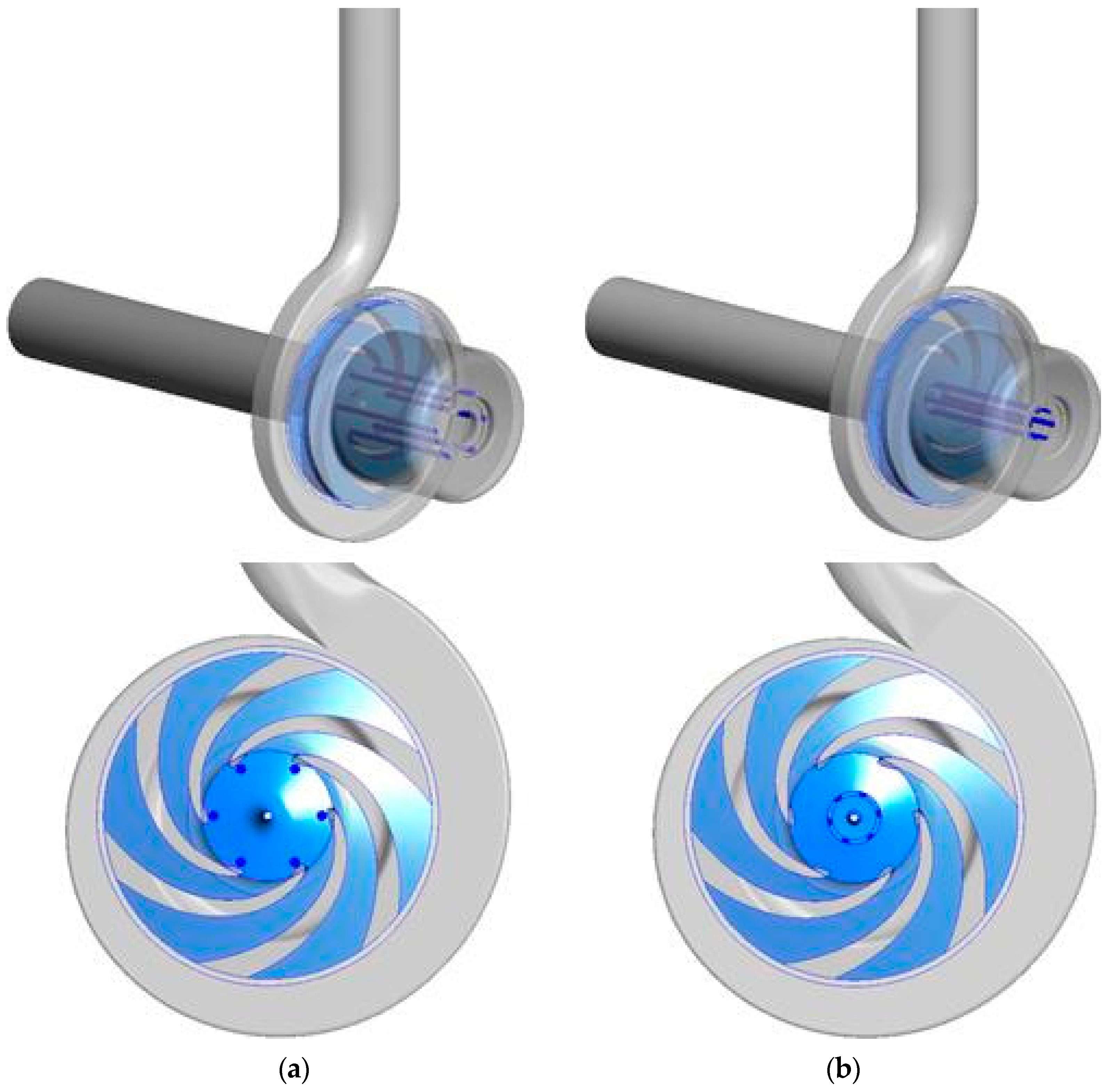
Figure 6 shows the comparison of the CFD analysis results between the pump model without balancing holes and Type A and B pump models with balancing holes. The Type A pump model was set with six balancing holes, 4 mm hole diameter, and hole position near the suction surface of the impeller blade, by referring to the general specifications of the centrifugal pump (see Figure 2a and Figure 3a). The Type B pump model was also set with six balancing holes and 4 mm hole diameter, and the hole position was set to the outer surface of the fixed shaft located at the same angle as the Type A pump model based on the impeller’s rotation axis (see Figure 2b and Figure 3b).
Figure 6a shows that the efficiency of the pump model without balancing holes is 71.6%. The efficiency of the Type A pump model is 46.9%, lower by approximately 25% than that of the pump model without balancing holes. However, the efficiency of the Type B pump model is 70.2%, only 1% lower than that of the pump model without balancing holes. Thus, in terms of efficiency, Type B balancing holes are much more advantageous than Type A balancing holes.
Figure 6b shows that the pump model without balancing holes has a head of 50.5 m, and the head of the Type A pump model is 41.1 m, lower by approximately 9 m than that of the pump model without balancing holes. However, the head of the Type B pump model is 50.4 m, which is not much different from that of the pump model without balancing holes. Therefore, Type B balancing holes are much more advantageous than Type A balancing holes in terms of the head size.
Figure 6c shows the calculation results of the axial thrust. First, the pump model without balancing holes has an axial thrust of approximately 1734.7 N. The pump with Type B balancing holes has an axial thrust of 1124.2 N, lower by 35% than the pump without balancing holes due to the balancing holes. However, the axial thrust of the pump with Type A balancing holes is −11071.0 N. This finding indicates that due to the balancing holes, an axial thrust of 1070.95 N acts in the opposite direction to that of the pump model without balancing holes. These results suggest that in the case of Type A balancing holes, an axial thrust acts in the opposite direction of the pump model without balancing holes due to the excessive reduction of the axial thrust, but in the case of Type B balancing holes, the axial thrust is lower by only a small amount.
Figure 7 and Figure 8 show the velocity contour and vector on the X–Y and X–Z planes of the pump model without balancing holes and pump models with Type A and B balancing holes, respectively. First, in Figure 7 and Figure 8a, for the pump model without balancing holes, some of the high-pressure water that passed through the blades is recycled to the low-pressure inlet through the front flow path (see Figure 1), but most water exits through the outlet via the volute. Furthermore, in the gap of the rear flow path (see Figure 1), water from the high-pressure volute is supplied and remains (not recycled) and only the wall inside the rear flow path rotates.
Furthermore, for the pump models with balancing holes in Figure 7 and Figure 8b,c, the low-pressure water that entered through the impeller inlet must exit through the outlet via the volute as high-pressure water after receiving energy through the blades, but some of the high-pressure water passed through the blades flow through the front and rear flow paths instead of the volute, resulting in leakage. In particular, unlike the model without balancing holes in Figure 7 and Figure 8a, for the models in Figure 7 and Figure 8b,c, as the high-pressure volute and low-pressure inlet of the impeller are interconnected through the rear flow path, a recycling flow path of water is formed inside the impeller. This condition causes rapid changes in the pressure distribution around the impeller and the speed distribution at the impeller inlet that is hit by water. Particularly, in Figure 7 and Figure 8b, for the model with balancing holes installed in the rotating impeller, the flow through the rear flow path rapidly increases and flow energy loss occurs due to the effect of increasing flow velocity and the vortex flow caused by the complicated flow path shape. Consequently, the pressure of water in the back of the impeller sharply decreases compared to those shown in Figure 7 and Figure 8a,c. The same result is shown in Figure 6.
Figure 9 and Figure 10 show the comparison of the distribution of entropy production on the X–Y and X–Z planes of the pump model without balancing holes and pump models with Types A and B balancing holes. Entropy production means the loss of viscous and turbulence dissipation by flow, and the flow loss distribution can be easily predicted by the distribution of entropy production [15,16].
The distribution of entropy production in Figure 9 shows that, first, at the impeller inlet, the entropy production has a large value due to the surface shear force by the rotation of the blade leading edge. At the impeller outlet, the closer to the outlet, the faster the flow velocity becomes due to the rotation of the impeller, and the larger the loss due to flow instability resulting from the increasing flow path area. In particular, Figure 9b,c for models with balancing holes show that the entropy production is large in the flow path area where recycling occurs due to the holes.
The distribution of entropy production on the X–Z plane in Figure 10 shows more clearly that the entropy production is large in the area where recycling increases due to the holes. In particular, for the model with balancing holes installed in the rotating impeller, Figure 9b shows an increase in the entropy production (loss of flow energy) due to the vortex flow near the back of the impeller constituting the rear flow path. It can be inferred that the result in Figure 6 was caused by this condition.
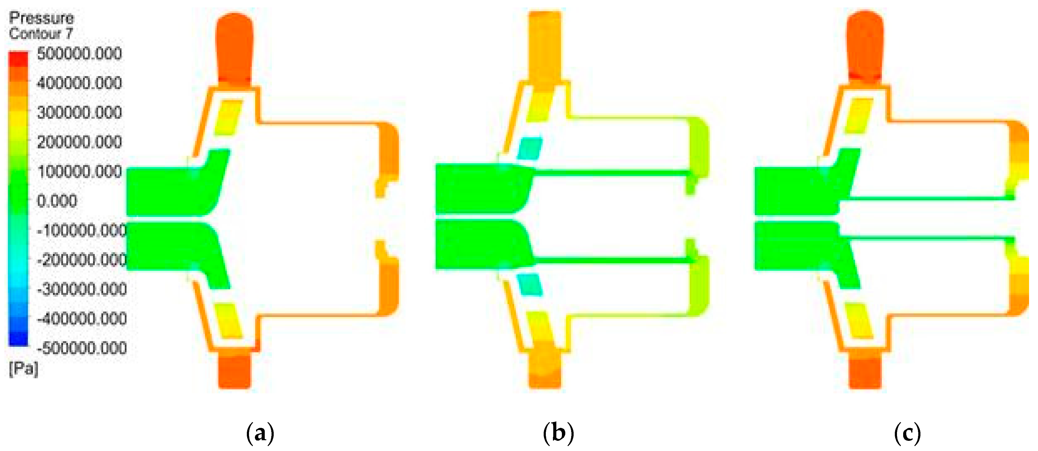
Figure 11 and Figure 12 show the pressure contours on the X–Y and X–Z planes of the pump model without balancing holes and the pump models with Type A and B balancing holes.
The pressure contour in Figure 11 shows that the pressure gradually increases as the low-pressure water, which was supplied from every pump through atmospheric pressure, and moves toward the outlet by receiving energy from the rotating impeller. For the pump model with balancing holes installed in the impeller, Figure 11b shows that the pressure at the outlet is the lowest compared to those shown in Figure 11a,c (see Figure 6b). The reason for this is that, as shown in the above figures, the largest flow loss occurs in the flow path where the water is recycled after passing through the rear flow path and the balancing holes, as shown in Figure 11b.
Figure 12 clearly shows the distribution of pressures in the recycling flow path created by the front flow path, balancing holes, and rear flow path. In the front flow path interconnecting the high-pressure volute and impeller inlet, a high-pressure flow is generated regardless of the balancing holes. However, the pressure distribution in the rear flow path is influenced by the existence or absence of balancing holes and the position of the shape. In Figure 12a, there is no recycling flow through the rear flow path because there are no balancing holes, but a high pressure occurs in the large space behind the rear flow path because it is connected to the volute through which high-pressure water flows. As a result, the pump without balancing holes receives a large axial thrust toward the front of the impeller during operation. However, in Figure 12b, for the pump model with balancing holes installed in the rotating impeller, there is a pressure reduction effect due to the increase in flow velocity as the flow through the rear flow path rapidly increases. Furthermore, the pressure of water at the rear of the impeller is rapidly reduced due to the loss of flow energy from the vortex flow, which is caused by the complicated flow path shape. Consequently, as shown in Figure 6c, a large axial thrust occurs toward the back of the impeller opposite to the direction in Figure 12a,c.
The above results show that the axial thrust in the pump impeller during operation can be removed with minimal efficiency reduction and head loss if the balancing holes of appropriate sizes are installed at proper positions in the impeller.

3.2. Pump Performance and Axial Thrust with Different Positions of Balancing Holes

Figure 13 shows the calculation results of the axial thrust and performance according to the diameter of balancing holes and the cooling water flow rate through the balancing hole flow path for Type A and B pump models.
The left graph in Figure 13a, comparing the axial thrust of each model when there are no balancing holes in the pump with Type A balancing holes, shows that an axial thrust of 1734.7 N is generated, but when there are balancing holes of 2 mm diameter, the axial thrust decreases to 395 N. Then, the axial thrust rapidly decreases with an increasing diameter, and the axial thrust becomes zero when the diameter is 2.9 mm (flow rate 0.4 kg/s). When the diameter increases to 7 mm, the axial thrust decreases further, showing a reverse axial thrust of −1868 N before gradually becoming constant. The right graph in Figure 13a shows the calculation results with the flow rate through the balancing holes instead of the diameter of the balancing holes. While the diameter of balancing holes changes from 2 to 12 mm, the flow rate through the balancing holes increases from 0.146 to 3.819 kg/s in proportion to the diameter of the balancing holes. This finding indicates that the axial thrust rapidly decreases due to the pressure relief at the back of the pump, according to the increase in the flow rate.
By contrast, when the diameter of the balancing holes was 2 mm, the pump with Type B balancing holes generated a forward axial thrust of 1238 N, which is larger than that of the pump with Type A balancing holes. Furthermore, as the diameter increased to 8.3 mm, the change in flow rate through the balancing holes was very small. Then, the flow rate sharply increased for a very small diameter change of 0.2 mm, which also rapidly decreased the axial thrust, showing a discontinuous trend of the flow rate. Due to the pump with Type B balancing holes, the flowing fluid does not receive the kinetic energy by motor rotation, unlike the pump with Type A balancing holes because the balancing holes are located on the outer wall of the inner shaft. As a result, a transient flow phenomenon occurs in the discontinuous section where the fluid flowing through the balancing hole flow path located on the fixed axis moves to the rotating impeller. Figure 14a shows the changes of the total pressure distribution at section A-A including the kinetic energy of the fluid according to the changes in the diameter of balancing holes for the pump with Type B balancing holes. Figure 14b shows the static pressure distribution at section A-A. In this figure, when the diameter of balancing holes is 8.3 mm or less, the flow rate is low because the energy is insufficient for the fluid to move to the front of the impeller by overcoming the resistance of the flow path only by the pressure of the fluid at the back of the impeller. Consequently, there is no significant change in the total pressure of the fluid flowing to the rotating impeller from the fixed balancing hole. However, when the hole diameter becomes larger than 8.5 mm, the high-pressure fluid at the back of the impeller can sufficiently overcome the resistance of the fixed flow path. Thus, the flow rate suddenly increases, and the total pressure inside the balancing holes increases. This phenomenon can be seen more clearly in Figure 14c. As shown in this figure, when the diameter of balancing holes is 8.3 mm or less, the fluid flowing through the fixed balancing hole flow path has insufficient energy to break through the main flow around the rotating impeller, but when it becomes larger than 8.5 mm, the fluid breaks through the main flow around the rotating impeller. Furthermore, as the flow path gradually expands, the surrounding pressure distribution becomes stabilized. Then, the axial thrust also decreases with an increasing diameter of the pump with Type B balancing holes, and the axial thrust becomes zero when the diameter becomes 10.5 mm (flow rate: 4 kg/s), as shown in Figure 13a.
Figure 13b,c show the calculation results of the changes in efficiency and head according to the diameter of the balancing holes and flow rate through the balancing holes for pumps with Type A and B balancing holes. In the balanced flow rate (Type A: 0.4 kg/s, Type B: 4 kg/s) or balanced hole diameter size (Type A: 2.9 mm, Type B: 10.5 mm), the efficiency of the Type A pump model is 55.1% and that of the Type B pump model is 52%. Thus, the efficiency of Type A is approximately 3.1% higher than that of Type B. Furthermore, the heads of the Type A and B pump models are 45.6 and 44.4 m, respectively. Thus, the head of Type A is higher by approximately 1.2 m. For this reason, Type A is often adopted for the balancing holes of general pumps. However, the magnetic drive centrifugal pump requires a sufficient amount of coolant unlike the general pump to prevent low efficiency (low torque transmission power) of the magnetic drive due to high heat around the magnetic drive during operation. Considering this structural characteristic, Type B balancing holes can be more appropriate for the design of balancing holes for magnetic drive centrifugal pumps, which can achieve a coolant with 10 times higher flow rate even if there is a small loss (efficiency 3.1%, head 1.2 m) in terms of efficiency and head. In particular, Type B balancing holes also have an advantage as the margin of the coolant flow design is relatively large because it has a smaller change in efficiency and head according to the change of the flow rate around the balanced position compared to Type A balancing holes, as shown in Figure 13.

4. Conclusions

To achieve an ideal design of balancing holes applied to a magnetic drive pump, the flow characteristics of two types of balancing holes with different characteristics within the available design range were examined in this study. The following conclusions were derived from the analysis:
  • The axial thrust behaviour, pump performance, and flow rate through the internal cooling circuit of the magnetic drive pump show completely different patterns according to the shape of balancing holes.
  • Type A balancing holes, which are directly drilled through the gap between the rotating impeller and inner magnet that is integrated and rotates with the impeller, can resolve the axial thrust with relatively small reductions of efficiency and head size than Type B balancing holes, which are drilled on the outer wall of the inner shaft, a fixed axis that holds the centre of the impeller.
  • In terms of securing the flow rate of the internal coolant to release heat generated during the magnet drive operation, the pump with Type B balancing holes can be more advantageous. Because it can achieve 10 times higher flow rate of the internal coolant at the balanced position and can remove the axial thrust without much loss in efficiency and head compared to Type A balancing holes.

Author Contributions

W.-S.K. conducted CFD, checked and organized the result data, and wrote this paper. J.-E.Y. checked the results and discussion and generally reviewed this paper. All authors have read and agreed to the published version of the manuscript.

Funding

This research was funded by the Korea Institute of Energy Technology Evaluation and Planning (KETEP) and the Ministry of Trade, Industry and Energy (MOTIE) of the Republic of Korea, grant number 20172010106090.

Acknowledgments

This work was supported by the Korea Institute of Energy Technology Evaluation and Planning (KETEP) and the Ministry of Trade, Industry and Energy (MOTIE) of the Republic of Korea (No. 20172010106090).

Conflicts of Interest

The authors declare no conflict of interest.

References

  1. Pehlivan, H.; Parlak, Z. Investigation of parameters affecting axial load in an end suction centrifugal pump by numerical analysis. J. Appl. Fluid Mech. 2019, 12, 1615–1627. [Google Scholar] [CrossRef]
  2. Lefor, D.; Kowalski, J.; Herbers, T.; Mailach, R. Investigation of the potential for optimization of hydraulic axial thrust balancing methods in a centrifugal pump. In Proceedings of the 11th European Conference on Turbomachinery Fluid dynamics & Thermodynamics, Madrid, Spain, 23–27 March 2015. [Google Scholar]
  3. Cao, W.; Dai, X.; Hu, Q. Effect of impeller reflux balance holes on pressure and axial force of centrifugal pump. J. Cent. South Univ. 2015, 22, 1695–1706. [Google Scholar] [CrossRef]
  4. Babayigit, O.; Ozgoren, M.; Aksoy, M.H.; Kocaaslan, O. The effect of balance holes to centrifugal pump performance. AIP Conf. Proc. 2017, 1863, 030004. [Google Scholar]
  5. Fanyu, K.; Jianrui, L.; Weidong, S.; Houlin, L.; Gang, C. Calculation of axial force balance for high-speed magnetic drive pump. Trans. Chin. Soc. Agric. Eng. 2005, 21, 69–72. [Google Scholar]
  6. Hong, S.; Kang, S. Effects of balancing holes on the performance and axial thrust of a centrifugal pump. Trans. Korean Soc. Mech. Eng. 2014, 23, 443–451. [Google Scholar] [CrossRef]
  7. Lee, G.; Heo, H.; Kim, H.; Oh, C. Effects of the balance holes diameter of an automotive closed type water pump on hydraulic performance and axial force. Trans. Korean Soc. Automot. Eng. 2008, 16, 111–117. [Google Scholar]
  8. Kim, D.; Choi, C.; Noh, J.; Kim, J. Axial thrust control of high-speed centrifugal pump with cavity vanes. KSFM J. Fluid Mach. 2012, 15, 46–50. [Google Scholar] [CrossRef] [Green Version]
  9. Choi, Y.; Kurokawa, J. A method of axial thrust control in centrifugal pump. KSFM J. Fluid Mach. 2007, 10, 15–20. [Google Scholar] [CrossRef]
  10. Lee, G.; Heo, H.; Kim, H.; Na, B.; Oh, C. Evaluations of the hydraulic flow force on the automotive closed type water pump with balance holes by means of a computational fluid dynamic analysis. In Proceedings of the Korean Society of Automotive Engineers Spring Conference, Changwon, Korea, 21–23 June 2019; pp. 1120–1126. [Google Scholar]
  11. Kim, W.; Yun, J. Optimum design of balancing holes in terms of centrifugal pump efficiency and axial thrust using CFD analysis. In Proceedings of the KSME 2019 Fall Conference, Jeju, Korea, 13–16 November 2019; pp. 500–505. [Google Scholar]
  12. Chaitanya, K. Boundary Layer Modeling Using Inflation Layers. Simulate Tomorrow. Available online: https://www.cadfem.in/blog/modeling-boundary-layer-inflation/ (accessed on 4 July 2017).
  13. ANSYS CFX. ANSYS CFX User’s Guide Release 15.0; ANSYS Inc.: Canonsburg, PA, USA, 2013. [Google Scholar]
  14. Yun, J. Development of a centrifugal pump impeller using optimal design technique. Trans. Korean Soc. Mech. Eng. B 2018, 42, 567–572. [Google Scholar] [CrossRef]
  15. Gong, R.; Qi, N.; Wang, H.; Chen, A.; Qin, D. Entropy production analysis for S-characteristics of a pump turbine. J. Appl. Fluid Mech. 2017, 10, 1657–1668. [Google Scholar] [CrossRef]
  16. Kock, F.; Herwig, H. Entropy production calculation for turbulent shear flows and their implementation in cfd codes. Int. J. Heat Fluid Flow 2005, 26, 672–680. [Google Scholar] [CrossRef]
Figure 1. 2D cross section of the magnetic drive pump.
Energies 13 05865 g001
Figure 2. 2D cross-section diagrams of the pump with two types of balancing holes: (a) Type A pump with balancing holes in the impeller; (b) Type B pump with balancing holes in the outer wall of the inner shaft.
Energies 13 05865 g002
Figure 3. 3D shapes of the two types of balancing holes: (a) Type A pump with balancing holes in the impeller; (b) Type B pump with balancing holes in the outer wall of the inner shaft.
Energies 13 05865 g003
Figure 4. Meshes created for the computational fluid dynamics (CFD) analysis of the pump model with Type A balancing holes.
Energies 13 05865 g004
Figure 5. Meshes created for the CFD analysis of the pump model with Type B balancing holes.
Energies 13 05865 g005
Figure 6. Comparison of the performance and axial thrust of the pump without balancing holes and pumps with six Type A and B balancing holes of 4 mm diameter.
Energies 13 05865 g006
Figure 7. Comparison of the X–Y plane velocity contour of the pump without balancing holes and pumps and Type A and B balancing holes of 4 mm diameter: (a) without balancing holes; (b) with Type A balancing holes; (c) with Type B balancing holes.
Energies 13 05865 g007
Figure 8. Comparison of the X–Z plane velocity vector and contour of the pump without balancing holes and pumps with six Type A and B balancing holes of 4 mm diameter: (a) without balancing holes; (b) with Type A balancing holes; (c) with Type B balancing holes.
Energies 13 05865 g008
Figure 9. Comparison of the entropy production on the X–Y plane of the pump without balancing holes and the pumps with six Type A and B balancing holes of 4 mm diameter: (a) without balancing holes; (b) with Type A balancing holes; (c) with Type B balancing holes.
Energies 13 05865 g009
Figure 10. Comparison of the entropy production on the X–Z plane of the pump without balancing holes and the pumps with six Type A and B balancing holes of 4 mm diameter: (a) without balancing holes; (b) with Type A balancing holes; (c) with Type B balancing holes.
Energies 13 05865 g010
Figure 11. Comparison of the pressure contour distribution on the X–Y plane of the pump without balancing holes and the pumps with six Type A and B balancing holes of 4 mm diameter: (a) without balancing holes; (b) with Type A balancing holes; (c) with Type B balancing holes.
Energies 13 05865 g011
Figure 12. Comparison of the pressure contour distribution on the X–Z plane of the pump without balancing holes and the pumps with six Type A and B balancing holes of 4 mm diameter: (a) without balancing holes; (b) with Type A balancing holes; (c) with Type B balancing holes.
Energies 13 05865 g012
Figure 13. Changes in the axial thrust and performance according to the diameter of balancing holes and the flow changes through the balancing holes of pump models with Type A and B balancing holes.
Energies 13 05865 g013
Figure 14. (a) Total pressure contours, (b) pressure contours, and (c) velocity vector distribution in box B at section A-A according the change in the diameter of balancing holes in the pump with Type B balancing holes.
Energies 13 05865 g014
Table 1. Operational specifications at the design points of the pump with balancing holes.
ItemsSpec.
Flow rate50 m3/h
Efficiency60%
Head45 m
Rotational speed 3450 rpm
Table 2. CFD analysis boundary conditions of Type A pump model.
ItemsConditions
FluidWater
No. mesh nodeImpeller3,987,091
Volute4,058,343
Front flow path1,284,602
Rear flow path1,912,880
DomainImpellerRotator
VoluteStator
Front flow pathStator
Rear flow pathStator
InterfaceStage
Inlet boundary conditions Temperature = 25 °C
Pressure = 1 atm.
Outlet boundary conditionsMass flow = 13.89 kg/s
Turbulence model SST
Rotational speed 3450 rpm
Table 3. CFD analysis boundary conditions of Type B pump model.
ItemsConditions
FluidWater
No. mesh nodeImpeller3,530,281
Volute4,058,343
Front flow path1,284,602
Rear flow path1,912,880
Holes flow path556,483
DomainImpellerRotator
VoluteStator
Front flow pathStator
Rear flow pathStator
Holes flow pathStator
InterfaceStage
Inlet boundary conditions Temperature = 25 °C
Pressure = 1 atm.
Outlet boundary conditionsMass flow = 13.89 kg/s
Turbulence model SST
Rotational speed 3450 rpm
Publisher’s Note: MDPI stays neutral with regard to jurisdictional claims in published maps and institutional affiliations.

